
BX 112H - Air conditioner BEKO - Free user manual and instructions
Find the device manual for free BX 112H BEKO in PDF.


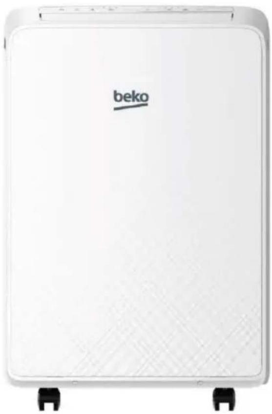
| Product type | Reversible mobile air conditioner (heat and cool) |
| Brand | Beko |
| Model | BX 112H |
| Packed unit dimensions (W x H x D) | 545 x 885 x 435 mm |
| Net weight of packed unit | 38.5 kg |
| Power supply | 220-240 V, 50 Hz, single phase |
| Refrigerant | R290 (flammable gas), 210 g |
| Cooling capacity | 3400 W (11600 BTU/h) |
| Heating capacity | 2700 W (9212 BTU/h) |
| Power consumption in cooling | 1303 W |
| Power consumption in heating | 964 W |
| Energy efficiency cooling | 2.61 W/W (class A) |
| Energy efficiency heating | 2.8 W/W (class A+) |
| Operating modes | Auto, Cooling, Heating, Dehumidification, Ventilation |
| Additional functions | 24h timer, Sleep mode, Auto oscillation, Auto restart |
| Air filter | Washable, cleaning recommended every 250 hours |
| Drainage | Manual or via drain hose (dehumidification mode) |
| Safety | Mandatory grounding, 30 mA differential circuit breaker, gas leak protection |
| Included accessories | Sliding window kit, exhaust hose, adapters, remote control with batteries, seals |
| Country of manufacture | Turkey (Arcelik A.S.) |
Frequently Asked Questions - BX 112H BEKO
User questions about BX 112H BEKO
0 question about this device. Answer the ones you know or ask your own.
Ask a new question about this device
Download the instructions for your Air conditioner in PDF format for free! Find your manual BX 112H - BEKO and take your electronic device back in hand. On this page are published all the documents necessary for the use of your device. BX 112H by BEKO.
USER MANUAL BX 112H BEKO
Local air conditioner
Installation Manual
natural_image
White rectangular electronic device labeled 'beko' with mounting feet (no additional text or symbols visible)BX109C | BX109H | BX112C BX112H | BX109AC | BX109AH
EN | FR
Please read this user manual first!
Dear Customer,
Thank you for preferring a Beko product. We hope that you get the best results from your product which has been manufactured with high quality and state-of-the-art technology. Therefore, please read this entire user manual and all other accompanying documents carefully before using the product and keep it as a reference for future use. If you handover the product to someone else, give the user manual as well. Follow all warnings and information in the user manual.
Meanings of the symbols
Following symbols are used in the various section of this manual:

Important information or useful hints about usage.

Warning for hazardous situations with regard to life and property.
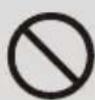
Warning to actions that must never perform.
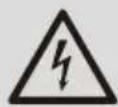
Warning for electric shock.
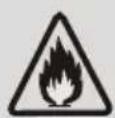
This symbol shows that this appliance uses a flammable refrigerant. If the refrigerant is leaked and exposed to an external ignition source, there is a risk of fire.
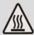
Warning for hot surfaces.
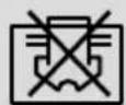
Do not cover it.

This symbol shows that the operation manual should be read carefully.
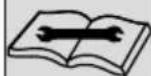
This symbol shows that a service personnel should be handling this equipment with reference to the installation manual.

This product has been produced in environmentally friendly, modern facilities
Contents
1 Safety precautions 5
2 Parts description 21
2.1 Front view....21
2.2 Rear view 21
3 Control panel 23
3.1 TEMP.indicator 23
3.2 Function buttons 23
4 Operation 25
5 Accessories 27
6 Notice of installation 28
6.1 Unpacking inspection....28
6.2 Safety principles for installing air conditioner 28
6.3 Requirements for installation position 28
6.4 Installation environment inspection 29
7 Installation 30
7.1 Guide of customer 30
7.2 Select a best location 30
7.3 Duct mount instruction 30
7.4 Install the window slider kit 31
7.5 Install the exhaust duct into the window 33
7.6 Without installation....34
7.7 Water drainage 34
Contents
8 Maintenance 36
8.1 Clean the unit 36
8.2 Clean the air filter 36
9 Troubleshooting 38
10 Installation instructions 39
10.1 F-Gas instruction....39
11 Specification 40
1 Safety precautions
Warning
This air conditioner uses R290 flammable refrigerant.

Note:
Air conditioner with R290 refrigerant, if roughly treated, may cause serious harm to the human body or surrounding things.
- The room space for the installation, use, repair, and storage of this air conditioner should be greater than 12 ~m^2 .
• Air conditioner refrigerant can not charge more than 250g. - Do not use any methods to speed up defrost or to clean frosty parts except for particular recommended by manufacturer.
- The appliance shall be stored in a well-ventilated area where the room size corresponds to the room area as specified for operation.
- Not pierce or burn air conditioner, and check the refrigerant pipeline whether be damaged.
- The air conditioner should be stored in a room without lasting fire source, for example, open flame, burning gas appliance, working electric heater and so on.
- Be aware that refrigerants may not contain an odour.
- The storage of air conditioner should be able to prevent mechanical damage caused by accident.
- The appliance must be kept free from obstruction to ensure proper function and mitigate safety hazards.
1 Safety precautions
- Maintenance or repair of air conditioners using R290 refrigerant must be carried out after security check to minimize risk of incidents.
- Please read the instruction carefully before installing, using and maintaining.
Warning
Incorrect installation or operation by not following these instructions may cause harm or damage to people, properties, etc.
The seriousness is classified by the following indications:
- This appliance can be used by children aged from 8 years and above if they have been given supervision or instruction concerning use of the appliance in a safe way and understand the hazards involved. Cleaning and user maintenance shall not be made by children unless they are aged from 8 years and above and supervised. Keep the appliance and its cord out of reach of children aged less than 8 years.
- This appliance is not intended for use by persons (including children) with reduced physical, sensory or mental capabilities, or lack of experience and knowledge, unless they have been given supervision or instruction concerning use of the appliance by a person responsible for their safety. Children should be supervised to ensure that they do not play with the appliance.
(Except for the AC with CE-Marking)
- This unit is designed for indoor use only.
1 Safety precautions
- The appliance shall be installed in accordance with national wiring regulations.
- The air conditioner must be grounded. Incomplete grounding may result in electric shocks.
Do not connect the earth wire to the gas pipeline, water pipeline, lightning rod, or telephone earth wire. - After installment, earth leakage examination must be carried on through electrifying.
- An earth leakage breaker with rated capacity must be installed to avoid possible electric shocks.
- Don't install air conditioner in a place where there is flammable gas or liquid. It may cause fire or explosion.
- If the power supply cord is damaged, it must be replaced by the manufacture or its service agent or a similar qualified person.
- The specification of the fuse are printed on the circuit bord, such as: AC 250V/5A.
- Don't put hands or any objects into the air inlets or outlets. This may cause personal injury or damage to the unit.
- Don't touch the swinging wind vanes. It may damp your finger and damage the driving parts of the wind vanes.
- Don't attempt to repair the air conditioner by yourself. You may be hurt or cause further malfunctions.
- In lighting storm weather, please cut off the primary power supply switch in order to prevent the machine from damage.
1 Safety precautions
- Don't use liquid or corrosive detergent to clean the appliance and don't splash water or other liquid onto it, otherwise, it may damage the plastic components, even cause electric shock.
- Don't operate the unit in a wet room such as the bath room or laundry rooms.
- Don't touch the unit with wet or damp hands or when barefoot.
- Don't pull the unit by the cord.
- Don't remove any part of the unit unless instructed by an authorized technician.
- Don't move the unit, unless the power has been cut off and the power cord is tied to the bending and winding column.
- Don't operate the unit with a damaged plug or a loose socket.
- Ducts connected to an appliance shall not contain an ignition source.
- Unplug before cleaning or maintenance operations.
- Do not use manuals to accelerate the defrosting process or to clean, other than those recommended by the manufacturer. The appliance shall be stored in a room without Continuously operation ignition sources (for example: open flames, an operation gas appliance or an operating electric heater.) Do not pierce or burn. Be aware that refrigerants may not contain an odour.
- The appliance shall state the insulation of a residual current device (RCD) having rated residual operating current not exceeding 30mA.
- This appliance is intended to be used in household and similar applications such as
1 Safety precautions
- Staff kitchen areas in shops, offices and other working environments;
- farm houses;
- by clients in hotels, motels and other residential type environments;
- bed and breakfast type environments;

Warning:
Any person who is involved with working on or breaking into a refrigerant circuit should hold a current valid certificate from an industry-accredited assessment authority, which authorises their competence to handle refrigerants safely in accordance with an industry recognised assessment specification.
Servicing shall only be performed as recommended by the equipment manufacturer. Maintenance and repair requiring the assistance of other skilled personnel shall be carried out under the supervision of the person competent in the use of flammable refrigerants.
Qualification requirements of maintenance personnel
- Special training additional to usual refrigerating equipment repair procedures is required when equipment with flammable refrigerants is affected. In many countries, this training is carried out by national training organisations that are accredited to teach the relevant national competency standards that may be set in legislation. The achieved competence should be documented by a certificate.
1 Safety precautions
- The maintenance and repair of the air conditioner must be conducted according to the method recommended by the manufacturer. If other professionals are needed to help maintain and repair the equipment, it should be conducted under the supervision of individuals who have the qualification to repair AC equipped with flammable refrigerant.
Inspection of the site
Safety inspection must be taken before maintaining equipment with R290 refrigerant to make sure the risk of fire is minimized. Check whether the place is well ventilated, whether anti-static and fire prevention equipment is perfect.
While maintaining the refrigeration system, observe the following precautions before operating the system.
Operating procedures
- General work area:
All maintenance staff and others working in the local area shall be instructed on the nature of work being carried out. Work in confined spaces shall be avoided. The area around the workspace shall be sectioned off. Ensure that the conditions within the area have been made safe by control of flammable material.
- Checking for presence of refrigerant:
The area shall be checked with an appropriate refrigerant detector prior to and during work, to ensure the technician is aware of potentially toxic or flammable atmospheres. Ensure that the leak detection equipment being used is suitable for use with
1 Safety precautions
all applicable refrigerants, i.e. non-sparking, adequately sealed or intrinsically safe.
- Presence of fire extinguisher:
If any hot work is to be conducted on the refrigeration equipment or any associated parts, appropriate fire extinguishing equipment shall be available to hand. Have a dry powder or CO_2 fire extinguisher adjacent to the charging area.
- No ignition sources:
No person carrying out work in relation to a refrigeration system which involves exposing any pipe work shall use any sources of ignition in such a manner that it may lead to the risk of fire or explosion. All possible ignition sources, including cigarette smoking, should be kept sufficiently far away from the site of installation, repairing, removing and disposal, during which refrigerant can possibly be released to the surrounding space. Prior to work taking place, the area around the equipment is to be surveyed to make sure that there are no flammable hazards or ignition risks.
'No Smoking' signs shall be displayed.
- Ventilated area (open the door and window):
Ensure that the area is in the open or that it is adequately ventilated before breaking into the system or conducting any hot work. A degree of ventilation shall continue during the period that the work is carried out. The ventilation should safely disperse any released refrigerant and preferably expel it externally into the atmosphere.
1 Safety precautions
- Checks to the refrigeration equipment:
Where electrical components are being changed, they shall be fit for the purpose and to the correct specification. At all times the manufacturer's maintenance and service guidelines shall be followed. If in doubt, consult the manufacturer's technical department for assistance. The following checks shall be applied to installations using flammable refrigerants:
- The charge size is in accordance with the room size within which the refrigerant containing parts are installed.
- The ventilation machinery and outlets are operating adequately and are not obstructed.
- If an indirect refrigerating circuit is being used, the secondary circuit shall be checked for the presence of refrigerant.
- Refrigeration pipe or components are installed in a position where they are unlikely to be exposed to any substance which may corrode refrigerant containing components, unless the components are constructed of materials which are inherently resistant to being corroded or are suitably protected against being so corroded.
- Checks to electrical devices:
Repair and maintenance to electrical components shall include initial safety checks and component inspection procedures. If a fault exists that could compromise safety, then no electrical supply shall be connected to the circuit until it is satisfactorily dealt with. If the fault cannot be corrected immediately but it
1 Safety precautions
is necessary to continue operation, an adequate temporary solution shall be used. This shall be reported to the owner of the equipment so all parties are advised.
Initial safety checks shall include:
- That capacitors are discharged: this shall be done in a safe manner to avoid possibility of sparking.
- That no live electrical components and wiring are exposed while charging, recovering or purging the system.
- Keep continuity of earthing.
Inspection of cable
Check the cable for wear, corrosion, overvoltage, vibration and check if there are sharp edges and other adverse effects in the surrounding environment. During the inspection, the impact of aging or the continuous vibration of the compressor and the fan on it should be taken into consideration.
Leakage check of R290 refrigeral

Note: Check the leakage of the refrigerant in an environment where there is no potential ignition source. No halogen probe (or any other detector that uses an open flame) should be used.
Leak detection method:
For systems with refrigerant R290, electronic leak detection instrument is available to detect and leak detection should not be conducted in environment with refrigerant. Make sure the leak
1 Safety precautions
detector will not become a potential source of ignition, and is applicable to the measured refrigerant. Leak detector shall be set for the minimum ignitable fuel concentration (percentage) of the refrigerant. Calibrate and adjust to proper gas concentration (no more than 25%) with the used refrigerant.
The fluid used in leak detection is applicable to most refrigerants. But do not use chloride solvents to prevent the reaction between chlorine and refrigerants and the corrosion of copper pipeline.
If you suspect a leak, then remove all the fire from the scene or put out the fire.
If the location of the leak needs to be welded, then all refrigerants need to be recovered, or, isolate all refrigerants away from the leak site (using cut-off valve). Before and during the welding, use OFN to purify the entire system.
Removal and vacuum pumping
- Make sure there is no ignited fire source near the outlet of the vacuum pump and the ventilation is well.
- Allow the maintenance and other operations of the refrigeration circuit should be carried out according to the general procedure, but the following best operations that the flammability is already taken into consideration are the key. You should follow the following procedures:
- Remove the refrigerant.
- Decontaminate the pipeline by inert gases.
- Evacuation.
1 Safety precautions
- Decontaminate the pipeline by inert gases again.
-
Cut or weld the pipeline.
-
The refrigerant should be returned to the appropriate storage tank. The system should be blown with oxygen free nitrogen to ensure safety. This process may need to be repeated for several times. This operation shall not be carried out using compressed air or oxygen.
-
Through blowing process, the system is charged into the anaerobic nitrogen to reach the working pressure under the vacuum state, then the oxygen free nitrogen is emitted to the atmosphere, and in the end, vacuumize the system. Repeat this process until all refrigerants in the system is cleared. After the final charging of the anaerobic nitrogen, discharge the gas into the atmosphere pressure, and then the system can be welded. This operation is necessary for welding the pipeline.
Procedures of charging refrigerants
As a supplement to the general procedure, the following requirements need to be added:
- Make sure that there is no contamination among different refrigerants when using a refrigerant charging device. The pipeline for charging refrigerants should be as short as possible to reduce the residual of refrigerants in it.
- Storage tanks should remain vertically up.
- Make sure the grounding solutions are already taken before the refrigeration system is charged with refrigerants.
1 Safety precautions
- After finishing the charging (or when it is not yet finished), label the mark on the system.
- Be careful not to overcharge refrigerants.
Scrap and recovery
Scrap:
Before this procedure, the technical personnel shall be thoroughly familiar with the equipment and all its features, and make a recommended practice for refrigerant safe recovery. For recycling the refrigerant, shall analyze the refrigerant and oil samples before operation. Ensure the required power before the test.
- Be familiar with the equipment and operation.
- Disconnect power supply.
-
Before carrying out this process, you have to make sure:
-
If necessary, mechanical equipment operation should facilitate the operation of the refrigerant tank.
- All personal protective equipment is effective and can be used correctly.
- The whole recovery process should be carried out under the guidance of qualified personnel.
-
The recovering of equipment and storage tank should comply with the relevant national standards.
-
If possible, the refrigerating system should be vacuumized.
-
If the vacuum state can't be reached, you should extract the refrigerant in each part of the system from many places.
1 Safety precautions
- Before the start of the recovery, you should ensure that the capacity of the storage tank is sufficient.
- Start and operate the recovery equipment according to the manufacturer's instructions.
- Don't fill the tank to its full capacity (the liquid injection volume does not exceed 80% of the tank volume).
- Even the duration is short, it must not exceed the maximum working pressure of the tank.
- After the completion of the tank filling and the end of the operation process, you should make sure that the tanks and equipment should be removed quickly and all closing valves in the equipment are closed.
- The recovered refrigerants are not allowed to be injected into another system before being purified and tested.

Note: The identification should be made after the appliance is scrapped and refrigerants are evacuated. The identification should contain the date and endorsement. Make sure the identification on the appliance can reflect the flammable refrigerants contained in this appliance.
Recovery:
- The clearance of refrigerants in the system is required when repairing or scrapping the appliance. It is recommended to completely remove the refrigerant.
- Only a special refrigerant tank can be used when loading the refrigerant into the storage tank. Make sure the capacity of the
1 Safety precautions
tank is appropriate to the refrigerant injection quantity in the entire system. All tanks intended to be used for the recovery of refrigerants should have a refrigerant identification (i.e.
refrigerant recovery tank). Storage tanks should be equipped with pressure relief valves and globe valves and they should be in a good condition. If possible, empty tanks should be evacuated and maintained at room temperature before use.
- The recovery equipment should be kept in a good working condition and equipped with equipment operating instructions for easy access. The equipment should be suitable for the recovery of R290 refrigerants. Besides, there should be a qualified weighting apparatus which can be normally used. The hose should be linked with detachable connection joint of zero leakage rate and be kept in a good condition.
Before using the recovery equipment, check if it is in a good condition and if it gets perfect maintenance. Check if all electrical components are sealed to prevent the leakage of the refrigerant and the fire caused by it. If you have any question, please consult the manufacturer.
-
The recovered refrigerant shall be loaded in the appropriate storage tanks, attached with a transporting instruction, and returned to the refrigerant manufacturer. Don't mix refrigerant in recovery equipment, especially a storage tank.
-
The space loading R290 refrigeration can't be enclosed in the process of transportation. Take anti electrostatic measures if necessary in transportation. In the process of transport, loading
1 Safety precautions
and unloading, necessary protective measures must be taken to protect the air conditioner to ensure that the air conditioner is not damaged.
- When removing the compressor or clearing the compressor oil, make sure the compressor is pumped to an appropriate level to ensure that there is no residual R290 refrigerants in the lubricating oil. The vacuum pumping should be carried out before the compressor is returned to the supplier. Ensure the safety when discharging oil from the system.
Warning
Failure to follow the below precaution could result in electrical shock, fire or personal injury.
- The plug must be plugged into an outlet that is properly installed and grounded.
- Do not use an extension cord or plug adaptor with this unit.
- Don't apply the cold air to the body for a long time. It will deteriorate your physical conditions and cause health problems.
- Don't block air inlet or air outlet, otherwise, the cooling/heating capacity will be weakened, even cause system stop operating.
- Close the windows and doors, otherwise, the cooling/heating capacity will be weakened.
- If the air filter is very dirty, the cooling/heating capacity will be weakened. Please clean the air filter regularly.
1 Safety precautions
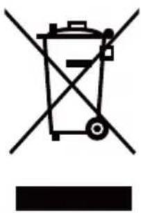
This product complies with EU WEEE Directive (2012/19/EU). This product bears a classification symbol for waste electrical and electronic equipment (WEEE).
This symbol indicates that this product shall not be disposed with other household wastes at the end of its service life. Used device must be returned to official collection point for recycling of electrical and electronic devices. To find these collection systems please contact to your local authorities or retailer where the product was purchased.
Each household performs important role in recovering and recycling of old appliance. Appropriate disposal of used appliance helps prevent potential negative consequences for the environment and human health.
natural_image
Symbol of a trash bin crossed with no visible text or labels2 Parts description
2.1 Front view
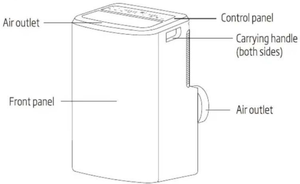
2.2 Rear view
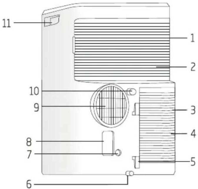
- Upper air filter (Behind the grille)
- Upper air intake
- Lower air filter (Behind the grille)
- Lower air intake
- Power cord buckle
-
Bottom tray drain outlet
-
Pump drain outlet
- Power plug socket
- Air outlet
- Drain outlet
- Carrying handle (both sides)
2 Parts description

Note:
- The descriptions in this user manual are text and figures may have slightly difference to the promotion information and actual appliance. Please refer to the real appliance purchased, Thank you.
- The woking temperature range of the air conditioner is 16-35°C (60-95°F) under cooling mode; 5-27°C (41-80°F) under heating mode.
3 Control panel
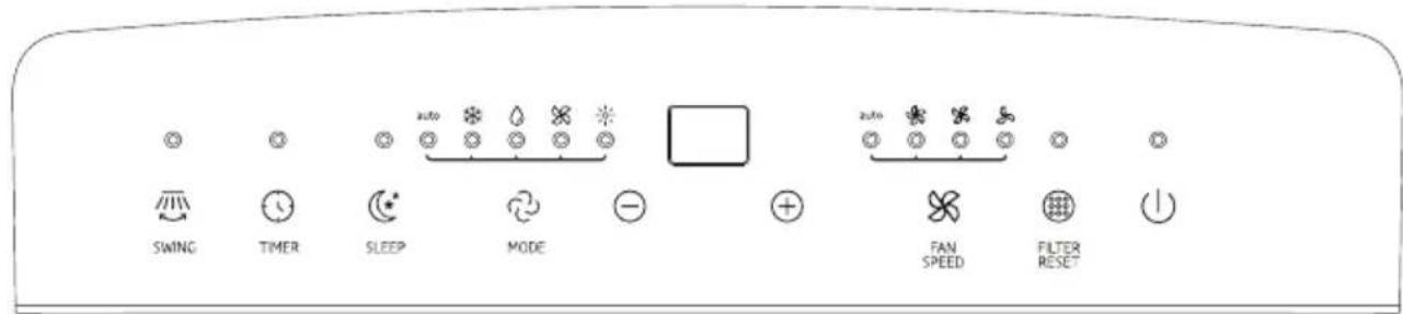
3.1 TEMP. indicator
In cooling or heating mode, when ● or ● button is pressed, the setting temperature is displayed and be adjusted.
- In auto, cool and heat mode, TEMP.indicator display is setting temperature.
- In dry and fan mode, TEMP.indicator display is room temperature.
3.2 Function buttons
- ⏻ button – Press this button to make the unit run or stop.
- ● button
a. The running time of the unit has reached 250 hours, the filter reset indicator light will illuminates, and it means the air filter should be cleaned.
After cleaning, you can press the "●" button, the filter reset indicator light will turn off and the running time will be cleared.
b. If you do not press the "●" button when the filter reset indicator light illuminates, the indicator light will always illuminates except the unit is power off.
- ✗ button – Press this button, you can select the fan speed as follows:

The fan speed indicator light illuminates under the different fan speed.

Note: In fan mode, do not have auto fan speed.
- ● or ⊕ button
a. Each time the ● or ● button is pressed, the setting temperature will increase or decrease by 1°C (1°F). The setting temperature ranges from 16°C (60°F)-32°C (90°F).
b. By pressing both the ● and ● button at the same time (≥3s), the display will toggle between Celsius and Fahrenheit.
3 Control panel
- 📋 button – Press this button, you can select the running mode as follows:

The mode indicator light illuminates under the different mode.

Note: Heat mode is not available for cool only units.
- ⚙ button – Press this button to enter sleep mode, which the unit will exit after 8 hours of continuous operation and restore to the previous status.

Note: The Sleep function can not be activated in fan and dry mode.
- ⏱ button
a. Press the "○" button, the timer indicator light illuminates.
b. Press ● or ● button to select the desired time.
c. After setting time 5 seconds without other operation, the timing function will be initiated automatically. If you press the TIMER button, there are no operation within 5 seconds or setting time is 0, the timing function will be cancelled automatically.
d. When the timing function is initiated, the unit displays the remaining time by press the "TIMER" button once and cancel the timing function by press it again.

Note:
With the unit on, press this button to set off timer.
With the unit off, press this button to set on timer.
- ☎ button-Press this button, the swing indicator light will illuminate.
4 Operation
Warning:
Failure to follow the below precaution could result in electrical shock, fire, explosion or personal injury.
-
The plug must be plugged into an individual socket that is properly installed and grounded.
-
Do not use an extension cord or plug adaptor with this unit.
Before starting the unit
- Select a suitable location, make sure the unit is near to an electrical outlet.
- Install the flexible exhaust hose and the adjustable window slider kit.
- Plug the unit into a right outlet.
Heating operation mode (Cool only unit has no heating function)
- Press the MODE button in a sequence until the heat indicator is lighted.
- Press the "●" and "●" button to setting your desired setting temperature.
- Press FAN button to select the fan speed.
Cooling operation mode
- Press the MODE button in a sequence until the cool indicator is lighted.
- Press the "●" and "●" button to set your desired setting temperature.
- Press FAN button to select the fan speed.
Drying operation mode
- Press the MODE button in a sequence until the dry indicator is lighted.
- The fan will run at a fixed speed at this operation mode.
- Close windows and doors for the best dehumidifying effect.

Note: The setting temperature and fan speed can not be adjusted. The setting temperature is 25^ C ( 77^ F) and the fan speed is low.
Fan operation mode
- Press MODE button in a sequence until the fan indicator is lighted.
- Press the FAN button to select the fan speed.

Note: The setting temperature can not be adjusted.
4 Operation
Auto-restart function:
If power to the unit is interrupted, the unit will restart itself in its last used mode/settings once power is restored. The compressor will restart after 4 minutes.
- Set: Press the SLEEP button 10 times within 5 seconds, buzzer sounds 4 times.
- Cancel: Press the SLEEP button 10 times within 5 seconds, buzzer sounds 2 times.
5 Accessories
| Parts | Parts name | Quantity |
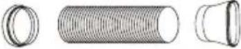 | Adaptor A, exhaust duct, Adaptor B (flat mouth) | 1 set |
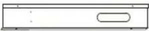 | Window Slider Kit (#) | 1 pc |
 | Type A Screws | 2 pc |
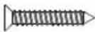 | Type B Screws | 6 pc |
 | Security bracket | 1 pc |
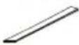 | Type A foam seal (adhesive) | 2 pc |
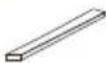 | Type B foam seal (non-adhesive) | 1 pc |
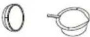 | Adaptor B (round mouth) (#), Wall exhaust Adaptor (#) | 1 set |
 | Drain hose | 1 pc |
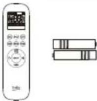 | Remote controller and Battery | 1 pc |

Note: Some models without optional parts (#).

Note: All the illustrations in this manual are for explanation purpose only. Your air conditioner may be slightly different, the actual shape shall prevail.

local air conditioner air louver notes:
- With automatic wind sweep function models, the air louver can not be less than automatically wind smallest outlet angle when use it.
- No automatic wind sweep function models, air louver minimum opening angle: from air louver closed state breaking up 5 grid. air louver can not be less than the minimum open angle when use it.
6 Notice of installation
6.1 Unpacking inspection
- Open the box and check unit in area with good ventilation (open the door and window) and without ignition source.

Note: Operators are required to wear anti-static devices.
- It is necessary to check by professional whether there is refrigerant leakage before opening the box; stop installing the air conditioner if leakage is found.
- The fire prevention equipment and anti-static precautions shall be prepared well before checking. Then check the refrigerant pipeline to see if there is any collision traces, and whether the outlook is good.
6.2 Safety principles for installing air conditioner
- Fire prevention device shall be prepared before installation.
- Keep installing site ventilated.(open the door and window)
- Ignition source, smoking and calling is not allowed to exist in area where R290 refrigerant located.
- Anti-static precautions in necessary for installing air conditioner, e.g. wear pure cotton clothes and gloves.
- Keep leak detector in working state during the installation.
- If R290 refrigerant leakage occurs during the installation, you shall immediately detect the concentration in indoor environment until it reaches a safe level. If refrigerant leakage affects the performance of the unit, please immediately stop the operation, and the unit must be vacuumed firstly and be returned to the maintenance station for processing.
- Keep electric appliance, power switch, plug, socket, high temperature heat source and high static away from the area underneath sidelines of unit.
- The unit shall be installed in an accessible location to installation and maintenance, without obstacles that may block air inlets or outlets of units, and shall keep away from heat source, inflammable or explosive conditions.
6.3 Requirements for installation position
- Avoid places of inflammable or explosive gas leakage or where there are strongly aggressive gases.
- Avoid places subject to strong artificial electric/magnetic fields.
- Avoid places subject to noise and resonance.
6 Notice of installation
- Avoid severe natural conditions (e.g. heavy lampblack, strong sandy wind, direct sunshine or high temperature heat sources).
- Avoid places within the reach of children.
- Select where it is easy to perform service and repair and where the ventilation good.
6.4 Installation environment inspection
- Check nameplate of unit to make sure whether the refrigerant is R290.
- Check the floor space of the room. The space shall not be less than usable space (12m ^2 ) in the specification. The unit shall be installed at a well-ventilated place.
- Check the surrounding environment of installation site: R290 shall not be installed in the enclosed reserved space of a building.
7 Installation
7.1 Guide of customer
- The customer should have a qualified power supply coincident with that printed on the tag of the air conditioner.
- Must use special circuit and efficient grounding outlet matching with the plug of the air conditioner.
- The appliance should be installed in accordance with national wiring regulation.
- The plug should be easily accessible after installation.
7.2 Select a best location
- Install the local air conditioner in a flat and spacious location where the air outlets will not be obstructed.
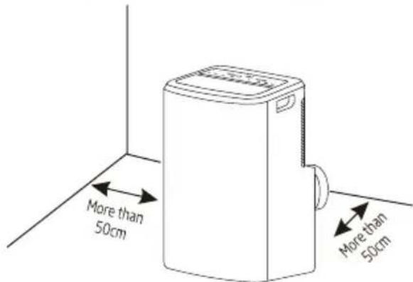
- A minimum clearance of 50cm from walls or other obstacles should be kept.
- The gradient can't be more than 10 degrees with the horizontal plane, while placing and using the unit.
Uneven ground may cause additional noise or vibration, or lead to damage to the unit.

Note:
- The air conditioner shall not be used in the laundry.
- The plug shall be accessible after the unit is positioned.
7.3 Duct mount instruction
- In cooling, heating and drying mode, the exhaust duct needs to be installed while in fan mode, the exhaust duct is not needed.
- According to the actual needs, the exhaust duct can be moderately compressed and tensed, but cannot be arbitrarily stretched and bent.
- The exhaust duct can be connected with Windows or installed into the wall. Based on accessories of the unit you buy and the actual needs, you can make the installation.
7 Installation
- Install the adaptor A and adaptor B (flat mouth or round mouth) onto the exhaust duct as shown in Fig. A or Fig. B.
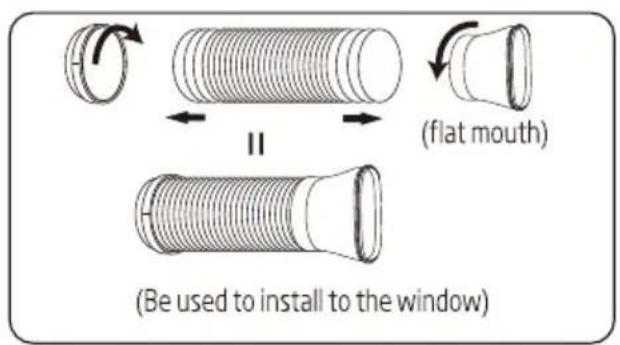
Fig. A
or
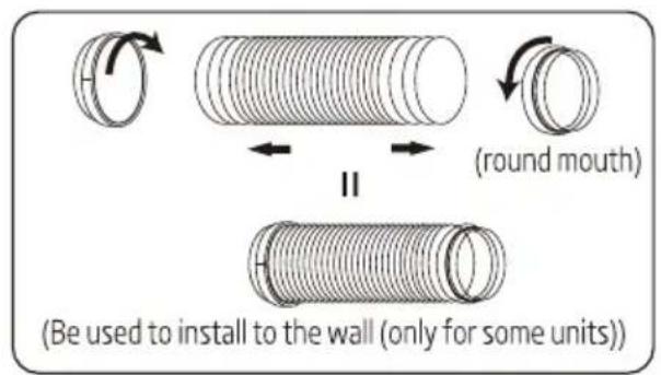
Fig. B
- Connect the exhaust duct to the Air outlet connector on back of the unit. Slide-in the adaptor A downwards until it is locked in place. (Fig. C)
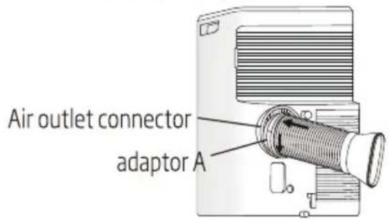
or
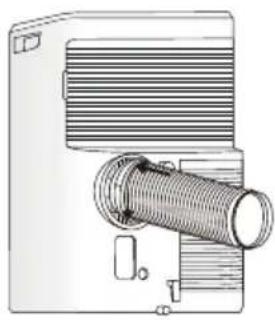
natural_image
Technical line drawing of a mechanical component with threaded shaft and housing (no text or symbols)Fig. C
7.4 Install the window slider kit
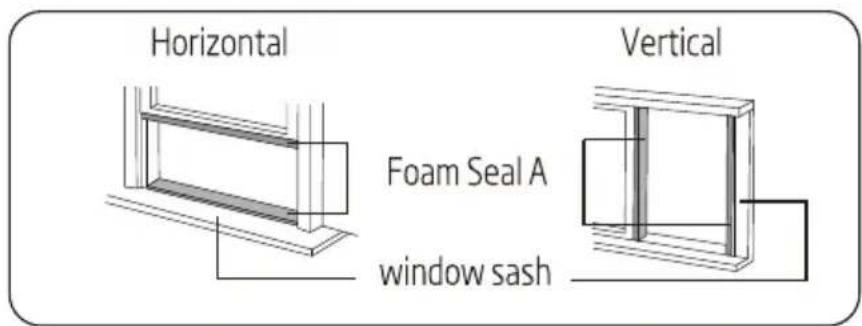
- Cut the foam seal (adhesive type) to the proper length and attach it to the window sash.
7 Installation
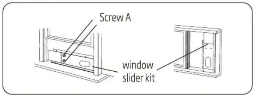
- Attach the window slider kit to the window sash. Adjust the length of the Window slider kit: Loose the screw A to adjust the length of the Window slider kit, then tight the screw when the length is suitable.

Note: The length of the Window Slider Kit is 67.5cm to 120cm.
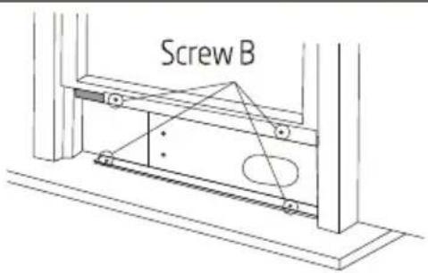
- Carefully lower the window. Secure the vent panel in place with 4 type B screws, plus one screw for each extension.
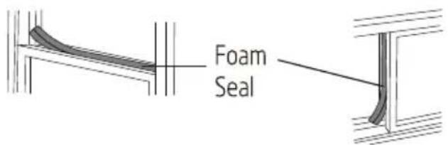
- Cut the foam seal B(non-adhesive) to the window width. Stuff the foam seal B between the glass and the window to prevent air and insects from getting into room.
natural_image
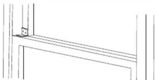
Pure architectural line drawing of a window frame with no text or symbols- Install the security bracket with a type B screw, as shown.
7 Installation
7.5 Install the exhaust duct into the window
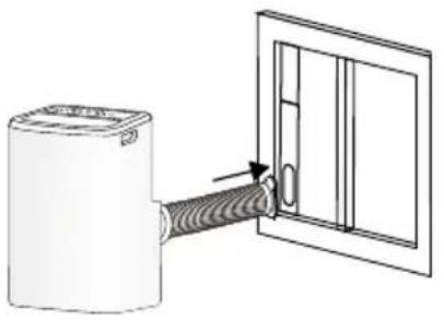
Remove the unit with the packed exhaust duct next to the window, and then connect the adaptor B (flat mouth) of the exhaust duct with the window. (Fig. E)
natural_image
Diagram of a cylindrical device connected to a door with a coiled cable, showing airflow direction (no text or symbols)Fig. E

Note: Cover the hole using the adaptor cap when not in use.

Note:
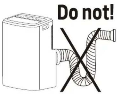
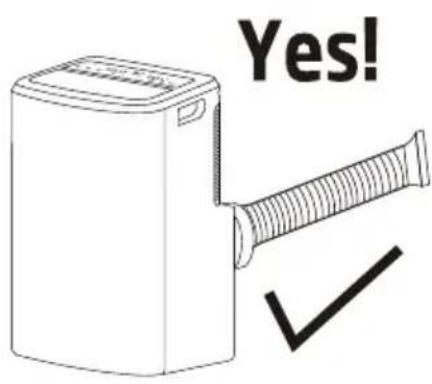
- The duct can be compressed to 270 mm minimum and extended to 1500 mm maximum. It is better to keep the duct length to a minimum.
- Stretching or bending the duct excessively will affect the cooling efficiency. (As the following fig. shows)
7 Installation
7.6 Without installation
If the unit does not have the window slider kit and wall exhaust, and the Adaptor B is like this, as shown in Fig G. You can open the window slightly and position as shown in Fig H.
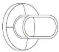
Fig. G
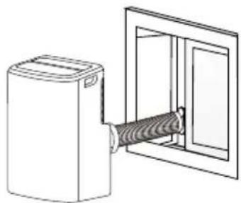
natural_image
Line drawing of a device with a coiled cable inside a transparent door (no text or symbols)Fig. H
7.7 Water drainage
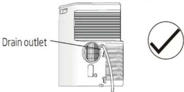
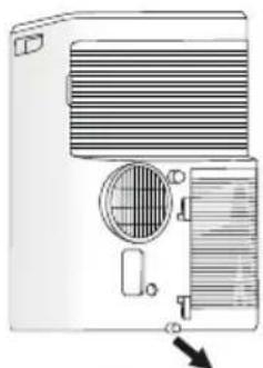
- During dehumidifying mode, remove the upper drain plug from the back of the unit. Attach the drain hose to the hole. Place the other end of the hose in the drainage way or other drain areas.
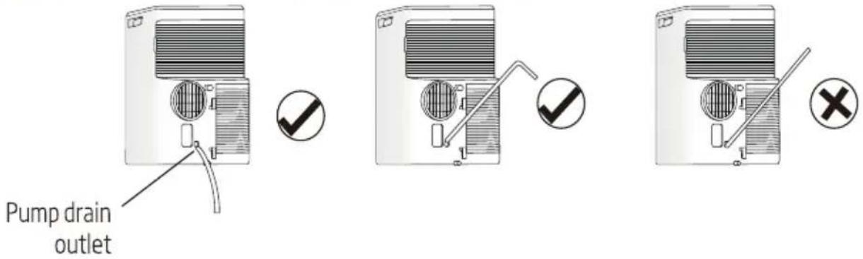
- If the unit you bought has the pump drain outlet, as shown below, please drain in this way: Remove the pump drain plug from the back of the unit, attach the drain hose to the hole. Place the other end of the hose in the drainage way or other drain areas.
7 Installation

Note: Make sure the hose is secure and there are no leaks. Direct the hose toward the drain, making sure that there are no kinks that will stop the water flowing. Place the end of the hose into the drain and make sure the end of the hose is down to let the water flow smoothly. Do never let it up.
- When the water level of the bottom tray reaches predetermined level, the digital display rea shows "P1" and the WATER FULL indicator light illuminates. Carefully move the unit to a drain location, remove the bottom drain plug and let the water drain away. Reinstall the bottom drain plug and restart the machine until the P1 symbol disappears. If the error repeats, call for service.
natural_image
Diagram of a portable air conditioner unit with ventilation slots and control panel (no text or labels)Bottom tray drain outlet

Note: Be sure to reinstall the bottom drain plug before using the unit.
8
Maintenance
Warning:
- Before the cleaning of the air conditioner, it must be shut down and the electricity must be cut off for more than 5 minutes, otherwise there might be the risk of electric shocks.
- Do not use gasoline, benzene, thinner or any other chemicals, or any liquid insecticide on the air conditioner, as these substances may cause flaking off of the paint, cracking or deformation of plastic parts.
- Never attempt to clean the unit by pouring water directly over any of the surface areas, as this will cause deterioration of electrical components and wirting insulation.
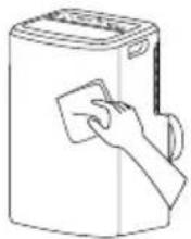
8.1 Clean the unit
When the unit is contaminated, clean it gently with a wrung towel using tepid water below 40^ C ( 104^ F).
8.2 Clean the air filter
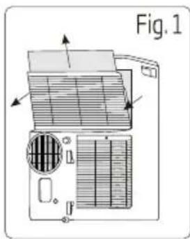
- Remove the air filter
Take out the upper air filter and the lower air filter.

Note: There are two types about the low air intake grille, please refer to Fig. 1 or Fig. 2. If the low air intake with a screw, please remove the screw at first.
natural_image
Technical diagram of a mechanical device with internal components and directional arrows, labeled Fig. 1 (no readable text or symbols)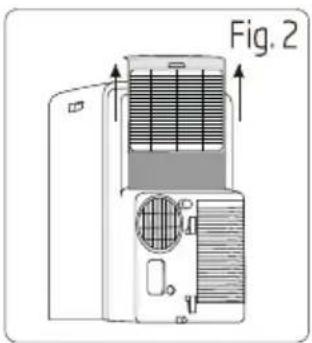
natural_image
Diagram of a refrigerant air conditioner unit with labeled component 'Fig. 2' (no text or symbols on the diagram itself)8 Maintenance
2. Clean the air filter
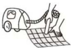
Use a vacuum cleaner or water to rinse filter, and if the filter is very dirty (for example, with greasy dirt), clean it with warm water (below 40^ C ( 104^ F)) with mild detergent dissolved in, and then put the filter in the shade to dry in the air.

natural_image
Simple line drawing of a bathtub with a plate and a bottle beside it (no text or symbols)- Reinstall the dried filter in reverse order of removal. Put the filter cover back to its place.
natural_image
Illustration of a vintage air conditioner unit with ventilation grille and fan (no text or symbols)
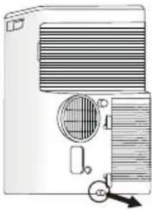
Note: If you don't use the unit for a long time, please pull out the rubber plug to drain the inside water out referring to right figure.
9 Troubleshooting
To save the cost of a service call, please try the suggestions below to see if you can solve your problem without outside help.
| Air condition will not operate | |
| Causes | Solutions |
| The power switch is released. | Switch on the power. |
| Power supply failure. | Wait for the recovery of power supply. |
| The fuse is burnt. | Replace the fuse by professional. |
| It doesn't reach the setting time for starting up. | Wait or eliminate the original setting. |
| Unit doesn’t start when pressing ON/OFF button | |
| Causes | Solutions |
| • It is not four minutes after switch off. | • Wait four minutes. |
| • Room temperature is lower than the setting temperature under cooling mode or higher than setting temperature under heating mode. | • Reset the setting temperature. |
| The wind blowing out, but the cooling/heating effect is bad | |
| Causes | Solutions |
| • Mistakes in temperature setting. | • Set a proper temperature, setting temperature should be lower than ambient temperature. |
| • The air filter is blocked by dust. | • Clean the air filter. |
| • The air inlet or outlet of machine is blocked. | • Remove the obstruction. |
| • Turn the air conditioner on in very hot room. | • Allow additional time to remove stored heat from walls ,ceiling, floor and furniture. |
| • Cooling capacity is insufficient. | • Reconfirm the required cooling/heating. capacity with your dealer. |
| • The doors or windows are open. | • Close the doors and windows. |
| Noise or vibration | |
| Causes | Solutions |
| • The ground is not level or not flat enough. | • Place the unit on a flat, level ground if possible. |
10 Installation instructions
10.1F-Gas instruction
This product contains fluorinated greenhouse gases covered by the Kyoto protocol.
The fluorinated greenhouse gases are contained in hermetically sealed equipment.
Installs, services, maintains, repairs, checks for leaks or decommissions equipment and product recycling should be carried out by natural persons that hold relevant certificates.
If the system has a leakage detection system installed, leakage checks should be performed at least every 12 months, make sure system operate properly.
If product must be performed leakage checks, it should specify Inspection cycle, establish and save records of leakage checks.

Note: For hermetically sealed equipment, local air conditioner, window air conditioner and dehumidifier, if CO_2 equivalent of fluorinated greenhouse gases is less than 10 tonnes, it should not perform leakage checks.
11 Specification
| Beko model name | BX 109 C | BX 109 H | BX 112 C | BX 112 H | BX 109 AC | BX 109 AH |
| Refrigerant | R290 | R290 | R290 | R290 | R290 | R290 |
| Total refrigerant amount (g) | 200 | 200 | 210 | 210 | 200 | 200 |
| Climate class | T1 | T1 | T1 | T1 | T1 | T1 |
| Cooling capacity (Btu/h) | 8871 | 8871 | 11600 | 11600 | 8871 | 8871 |
| Cooling capacity (W) | 2600 | 2600 | 3400 | 3400 | 2600 | 2600 |
| Heating capacity (Btu/h) | / | 7848 | / | 9212 | / | 7848 |
| Heating capacity (W) | / | 2300 | / | 2700 | / | 2300 |
| Energy efficiency cooling (W/W) | 2.61 | 2.61 | 2.61 | 2.61 | 3.1 | 3.1 |
| Energy efficiency heating (W/W) | / | 3.0 | / | 2.8 | / | 3.1 |
| Energy level-cooling | A | A | A | A | A+ | A+ |
| Energy level-heating | / | A+ | / | A+ | / | A++ |
| Cooling power input (W) | 996 | 996 | 1303 | 1303 | 839 | 839 |
| Heating power input (W) | / | 767 | / | 964 | / | 742 |
| Power of electric heater (W) | - | - | - | - | - | - |
| Voltage/frequency (V/Hz) | 220~240V-1-50Hz | 220~240V-1-50Hz | 220~240V-1-50Hz | 220~240V-1-50Hz | 220~240V-1-50Hz | 220~240V-1-50Hz |
| Packed unit (WxHxD) mm | 545*885*435 | 545*885*435 | 545*885*435 | 545*885*435 | 545*885*435 | 545*885*435 |
| Unit weight - packed (kg) | 36.5 | 37.5 | 38.0 | 38.5 | 37.5 | 38.0 |
Manufactured by Arcelik A.S. Karaagac Cd. No:2-6 34445 Sutluce, Beyoglu, Istanbul, Turkey. Importer in France
Attention! Surfaces chaudes!
Ne pas couvrir.

natural_image
Simple line drawing of a trash bin with crossed lines indicating no waste or discharge (no text or symbols)natural_image
Pure architectural line drawing of a window frame with no text or symbolsnatural_image
Diagram of a device connected to a door panel with a coiled cable (no text or symbols)Figure E

natural_image
Line drawing of a device with a coiled cable inserted into a door (no text or symbols)Figure H
natural_image
Technical diagram of a mechanical device labeled Fig. 1, showing internal components and directional arrows (no text or symbols beyond label)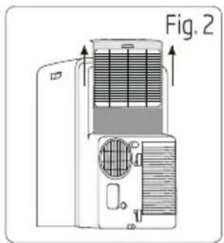
natural_image
Diagram of a refrigerant air conditioner unit with labeled component 'Fig. 2' (no text or symbols on the diagram itself)8 Entretien
natural_image
Simple line drawing of a washing machine with a bottle and towel (no text or symbols)natural_image
Diagram of a portable air conditioner unit with ventilation grilles and fan (no text or labels)
natural_image
Abstract geometric design with blue triangular shapes on white background (no text or symbols)Remote controller
User Manual
BX 109 C BX 109 H BX 112 C
BX 112 H BX 109 AC BX 109 AH
EN FR

Please read this user manual first!
Dear Customer,
Thank you for preferring a Beko product. We hope that you get the best results from your product which has been manufactured with high quality and state-of-the-art technology. Therefore, please read this entire user manual and all other accompanying documents carefully before using the product and keep it as a reference for future use. If you handover the product to someone else, give the user manual as well. Follow all warnings and information in the user manual.
Meanings of the symbols
Following symbols are used in the various section of this manual:

Important information or useful hints about usage.

Warning for hazardous situations with regard to life and property.

Warning to actions that must never perform.
Warning for electric shock.
This symbol shows that this appliance uses a flammable refrigerant. If the refrigerant is leaked and exposed to an external ignition source, there is a risk of fire.
Warning for hot surfaces.

Do not cover it.

This symbol shows that the operation manual should be read carefully.
This symbol shows that a service personnel should be handling this equipment with reference to the installation manual.

This product has been produced in environmentally friendly, modern facilities
Contents
1 Precautions 4
2 Buttons description 6
3 Usage 9
3.1 Fix batteries 9
3.2 Auto operation mode 9
3.3 Cooling/Heating operation mode 9
3.4 Fan operation mode....10
3.5 Drying operation mode 10
1 Precautions
Before first time use of the remote controller, install the batteries and ensure the "+" and "-" poles are correctly positioned.
Ensure the remote controller is pointed to the signal receiving window, and that there is no obstruction in between and the distance is 8m at the maximum.
Do not let the remote controller drop or fling it at will.
Do not let any liquid in the remote controller.
Do not expose the remote controller directly to the sunlight or excessive heat.
If the remote controller does not function normally, remove the batteries for 30 second before reinstall them. If that doesn't work, replace the batteries.
When replacing the batteries, do not mix the new batteries with old ones or mix batteries of different types, which could cause failure of the remote controller.
If the remote controller is not to be used for a long period of time, remove the batteries first, lest the leakage from them may damage the remote controller.
Properly dispose the discarded batteries.
1 Precautions

Note:
- This is a universal remote controller which provide all the function buttons. Please understand that some of the buttons may not function, depending on the specific air conditioner you have purchased. (If a specific function is not available on the air conditioner, pressing the corresponding button will simply have no respond.)
- Heat and ELE.H functions are not available for cool only models, thus these two buttons do not work correspondingly.
2 Buttons description
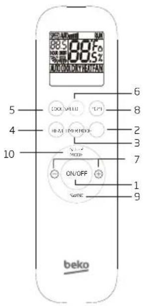

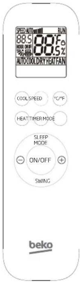
Note: The remote controller display all symbols during power-on and only those corresponding to current operation the rest of the time.
1. ON/OFF button
Press this button to turn on/off the unit.
This will clear the existing timer and SLEEP settings.
2. MODE button
Press this button, you can select the running mode as follows:

flowchart
graph LR
    A["AUTO COOL DRY HEAT FAN"] --> B["→"]
    B --> C["→"]

Note: HEAT mode is not available for cool only units.
3. TIMER button
With the unit ON, press this button to set OFF timer or with it OFF to set ON timer.
Press this button once, a "ON (OFF)" will flash. Press "+" or "-" to set the number of hours in which the unit will be turned ON/OFF, with an interval of 0.5 hour, and a range of 0.5-24 hours.
Press it again to confirm the setting, the "ON(OFF)" will stop flashing.
If the timer button is not pressed longer than 10 seconds after the "ON (OFF)" start flashing, the timer setting will be exited.
If a timer setting is confirmed, pressing this button again will cancel it.
2 Buttons description
4. HEAT button
Press this button to enter HEAT mode.
5. COOL button
Press this button to enter COOL mode.
6. SPEED button
Press this button, you can select the fan speed as follows:

flowchart
graph LR
    A["Low (•)"] --> B["Mid (■■)"]
    B --> C["High (■■■)"]
    C --> D["Auto (Auto)"]

Note: Auto air speed is not available in Fan mode.
7. + & - button
Each time the “+” is pressed, the temperature setting will increase by 1 °C and each time the “-” is pressed, it will decrease by 1°C.
The temperature setting ranges from 16^ C ( 60^ F) - 32^ C ( 90^ F).

Note: The temperature cannot be set in Auto or Fan mode.
8. °C & °F button
Press °C & °F Button to switch the display of degrees Celsius and degrees Fahrenheit on the screen.
9. SWING button
Press this button to activate up/down swing and press it again to fix the swing position.
10. SLEEP button
When the unit is on, press sleep mode button, which will activate (deactivate) the function of sleep mode.
The unit will exit SLEEP mode after 10 hours of continuous operation and restore to the previous status.

Note: The SLEEP function cannot be activated in FAN and AUTO mode. In the sleep mode, the screen of the air-conditioner is off.
2 Buttons description
11. Child-lock
Press the "HEAT" and "MODE" buttons at the same time and hold for at least 3 seconds to activate or deactivate the child-lock function.
When the child-lock function is activated, the remote control will indicate “☐”.
3 Usage
3.1 Fix batteries
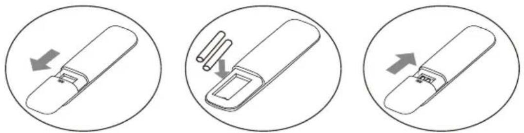
- Slide to open the cover according to the direction indicated by the arrowhead.
- Insert two brand new batteries (7#), and position the batteries to the right electric poles (+&-).
- Put back the cover.
3.2 Auto operation mode
- Press the "MODE" button, select the auto operation mode.
- By pressing the "SPEED" button, you can select the fan speed from Low, Mid, High, Auto.
- Press the "ON/OFF" button, the air-conditioner starts to operate.
- Press the "ON/OFF" button again, the air-conditioner stops.

Note: In the Auto mode, the temperature settings is non-effective.
3.3 Cooling/Heating operation mode
- Press the "MODE" button, select the Cooling or Heating operation mode.
- By pressing the "+" or "-" button, you can set the temperature range from 16°C (60°F) - 32°C (90°F), the display changes as you touch the button.
- By pressing the "SPEED" button, you can select the fan speed from Low, Mid, High, Auto.
- Press the "ON/OFF" button, the air-conditioner starts to operate.
- Press the "ON/OFF" button again, the air-conditioner stops.

Note: The cold wind type has no heating function.
3 Usage
3.4 Fan operation mode
- Press the "MODE" button, select the fan operation mode.
- By pressing the "SPEED" button, you can select the fan speed from Low, Mid, High.
- Press the "ON/OFF" button, the air-conditioner starts to operate.
- Press the "ON/OFF" button again, the air-conditioner stops.

Note: In the fan mode, the temperature settings is non-effective.
3.5 Drying operation mode
- Press the "MODE" button, select the drying operation mode.
- By pressing the "+" or "-" button, you can set the temperature range from 16°C (60°F)-32°C (90°F), the display changes as you touch the button.
- Press the "ON/OFF" button, the air-conditioner starts to operate.
- Press the "ON/OFF" button again, the air-conditioner stops.

Note: In the dry mode, the speed settings is non-effective.
Manufactured by Arcelik A.S. Karaagac Cd. No:2-6 34445 Sutluce, Beyoglu, Istanbul, Turkey.
Importer in France
Attention! Surfaces chaudes!

Ne pas couvrir.

4. Touche HEAT (Chauffage)
9. Touche SWING (Oscillation)
natural_image
Abstract geometric design with blue triangular shapes on white background (no text or symbols)- Local air conditioner
- Please read this user manual first!
- Meanings of the symbols
- Contents
- Safety precautions 5
- Parts description 21
- Control panel 23
- Operation 25
- Accessories 27
- Notice of installation 28
- Installation 30
- Maintenance 36
- Troubleshooting 38
- Installation instructions 39
- Specification 40
- Safety precautions
- Warning
- Note:
- Warning:
- Qualification requirements of maintenance personnel
- Inspection of the site
- Operating procedures
- Initial safety checks shall include:
- Inspection of cable
- Leakage check of R290 refrigeral
- Leak detection method:
- Removal and vacuum pumping
- Procedures of charging refrigerants
- Scrap and recovery
- Scrap:
- Recovery:
- Parts description
- Front view
- Rear view
- Control panel
- TEMP. indicator
- Function buttons
- Operation
- Before starting the unit
- Heating operation mode (Cool only unit has no heating function)
- Cooling operation mode
- Drying operation mode
- Fan operation mode
- Auto-restart function:
- Accessories
- local air conditioner air louver notes:
- Notice of installation
- Unpacking inspection
- Safety principles for installing air conditioner
- Requirements for installation position
- Installation environment inspection
- Installation
- Guide of customer
- Select a best location
- Duct mount instruction
- Install the window slider kit
- Install the exhaust duct into the window
- Without installation
- Water drainage
- 8
- Maintenance
- Clean the unit
- Clean the air filter
- Maintenance
- Clean the air filter
- Troubleshooting
- Installation instructions
- 10.1F-Gas instruction
- Entretien
- Remote controller
- User Manual
- Precautions 4
- Buttons description 6
- Usage 9
- Precautions
- Buttons description
- ON/OFF button
- MODE button
- TIMER button
- HEAT button
- COOL button
- SPEED button
- + & - button
- °C & °F button
- SWING button
- SLEEP button
- Child-lock
- Usage
- Fix batteries
- Auto operation mode
- Cooling/Heating operation mode
- Fan operation mode
- Drying operation mode
- Touche HEAT (Chauffage)
- Touche SWING (Oscillation)
Brand : BEKO
Model : BX 112H
Category : Air conditioner