
Optima 901 - Central heating boiler FERROLI - Free user manual and instructions
Find the device manual for free Optima 901 FERROLI in PDF.


| Type of product | Central heating boiler |
| Brand | Ferroli |
| Model | Optima 901 |
| Dimensions (H x W x D) | 900 x 600 x 400 mm |
| Weight | 30 kg |
| Power supply | 230 V / 50 Hz |
| Fuel type | Natural gas |
| Heat output | 18-24 kW |
| Main functions | Central heating, domestic hot water production |
| Display | Digital with operational indicators |
| Control panel | User-friendly with temperature adjustment |
| Efficiency class | B (approx. 90%) |
| Safety features | Flame failure device, overheat protection, frost protection |
| Maintenance | Annual service by qualified technician recommended |
| Cleaning | External surfaces wipe with damp cloth; internal cleaning by professional |
| Spare parts availability | Yes, through authorized dealers |
| Repairability | Modular design for easy component replacement |
| Installation | Wall-mounted, requires professional installation |
| Warranty | Standard 2 years (may vary by region) |
| Manual language | English |
Frequently Asked Questions - Optima 901 FERROLI
User questions about Optima 901 FERROLI
0 question about this device. Answer the ones you know or ask your own.
Ask a new question about this device
Download the instructions for your Central heating boiler in PDF format for free! Find your manual Optima 901 - FERROLI and take your electronic device back in hand. On this page are published all the documents necessary for the use of your device. Optima 901 by FERROLI.
USER MANUAL Optima 901 FERROLI
WALL MOUNTED, ROOM SEALED, FAN ASSISTED, GAS COMBINATION BOILER

Installer ____
Service Engineer ____
Serial No. ____

USERS INSTRUCTIONS
Read these Instructions thoroughly before using the appliance
FERROLI HELPLINE FOR SERVICE INFORMATION OR HELP TELEPHONE: 0121 3523500 ALWAYS QUOTE YOUR SERIAL NUMBER FOR IMMEDIATE ASSISTANCE
DIGITAL CLOCK

G.C. NO: 47-267-18
Conditions of Installation
GAS SUPPLY
It is the law that all gas appliances are installed and serviced by a competent person in accordance with the Gas Safety Regulations (Installation & Use) 1994, and the manufacturers instructions. Failure to observe these requirement may lead to prosecution.
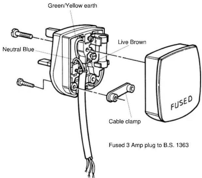
ELECTRICAL SUPPLY 230 V \~ 50 Hz FUSED 3A.
The electrical wiring must be carried out by a qualified electrician.
The colours of the wires in the mains lead of this appliance may not correspond with the coloured markings identifying the terminal in the plug. Therefore proceed as follow:
The wire coloured green and yellow must be connected to the terminal in the plug marked with either the letter E or by the earth symbol or coloured green or green and yellow. The wire coloured blue must be connected to the terminal marked either with the letter N or coloured black. The wire coloured brown must be connected to the terminal marked either with the letter L or coloured red.
MINIMUM CLEARANCE
The minimum clearance around the appliance should be as follows:
Sides 5 mm
Front 600 mm
Below200 mm
Above100 mm
Note: If a side outlet flue is to be used, a clearance of 75 mm will be needed on the flue outlet side of the boiler.
Boiler Lighting Instructions

Important: the Control system has a built in waiting time for Central Heating. A max. 3 minutes delay following shut down of Boilerstat, Clock, Roomstat or use of Hot Water is normal.
- Open control panel cover by pulling at either side.
- Ensure that the C.H./D.H.W. selector switch is set for: "Heating Continuous and Hot Water".
- Ensure that the electricity supply is turned on.
- Ensure that the heating system is filled with water and has not been drained down. (Pressure gauge should read 1.0 bar minimum).
- Adjust the room thermostat (if fitted) to a high setting.
- Adjust the boiler thermostat to its maximum setting. After a waiting time of max 3 minutes, fan in boiler will commence to run and 20 seconds must elapse before continuing.
- Depress the gas control knob fully (this should operate the electronic ignitor). When the pilot flame is seen to light in the pilot viewing opening, keep the control knob fully depressed for a further 15 seconds, then release it.
Should the pilot fail to remain alight, (or go out for any reason), then wait a full 3 minutes before attempting to relight the pilot. Should the pilot still fail to remain alight, turn the boiler off and contact your installer. - With the pilot burner established, observe that the main burners cross-light smoothly.
- Set the time clock, room thermostat (if fitted) and the boiler thermostat to their desired settings.
Note 1 - The main burner will light whenever a hot tap is turned on.
Note 2 - If the electricity supply is switched off for any reason, ensure that the pilot burner has remained alight.
If the boiler has gone out, follow «The Boiler Lighting Instructions» for relighting it.
To Shut Down The Boiler For Short Periods
- Set the C.H./D.H.W. selector switch to hot water. (In this position the pilot burner will remain alight, and the main burner will only operate when domestic hot water is required).
To Shut Down The Boiler For Long Periods
- Turn the gas control knob fully clockwise (approximately 1/12 of a turn). This will turn the pilot burner out.
- Turn off the electricity supply.
Boiler Controls
1.0 CENTRAL HEATING SELECTOR SWITCH
The central heating selector switch has three positions, these are:
a) Heating Timed & Hot Water
For domestic hot water supply and central heating controlled by the time clock.
b) Hot Water
For domestic hot water supply only.
b) Heating Continuous & Hot Water
For the domestic hot water supply and continuous central heating.
Note - When central heating is not required the selector switch must be turned to the position marked "Hot Water".
2.0 TIME CLOCK
A time clock is fitted to the boiler to control the Central Heating, this will come into operation when the Selector Switch is turned to the position marked "Heating timed and Hot Water"
3.0 BOILER THERMOSTAT TEMPERATURE SETTING (Central Heating)
The boiler water temperature can be set by the boiler thermostat knob, which is variable from minimum to maximum. This control knob does not affect the temperature of the domestic Hot Water.
4.0 DOMESTIC HOT WATER
When any domestic hot water tap is turned on the boiler will provide hot water. At minimum flow rate the water will be approximately 70° C and a maximum flow rate the water will be approximately 40° C (normal running is approximately 60° C).
5.0 SERVICING
The boiler must be checked and serviced by your installer or other competent person at least once a year.
General Notes
1.0 ESPACE OF GAS
Should a gas leak be suspected, turn off the gas supply at the meter then contact the Local Region of British Gas P.L.C. without delay.
2.0 SYSTEM WATER PRESSURE
If the water pressure in the central heating system, as indicated by the pressure gauge, falls below 1.0 bar, contact your installer, Service Engineer or other competent person to top it up.
3.0 VENTILATION
If the appliance is installed in a compartment or cupboard, do not obstruct any purpose provided ventilation openings. Do not use the compartment or cupboard for storage purposes.
4.0 FROST PROTECTION
Note - The boiler has its own built-in frost protection which automatically fire the boiler in low temperature situations irrespective of the selector switch setting. Electricity supply must be left on.
For frost protection of the system (radiator, etc.), a frost thermostat can be fitted, or if the boiler is turned off for long periods contact your installer or other competent person to drain the system. The system must be re-filled by your installer or other competent person.
5.0 HIGH LIMIT CUT-OFF THERMOSTAT
The boiler is fitted with a safety overheat cut-off thermostat, should it operate the pilot burner will go out. Should this happen, wait at least 3 minutes before attempting to re-light the boiler. The boiler should be relight in accordance with the «Boiler Lighting Instructions». If the safety overhead cut-off thermostat continues to fail consult your installer, service engineer or other competent person.
6.0 If the pump sticks, it can usually be freed by removing the chrome center screw (a small amount of water will escape) and manually free the impeller using a screwdriver in the end of the shaft.
Simple Checks
If a fault is suspected or discovered, you should contact your installer, service engineer or other competent person. The following list however, is a series of simple checks that should be made before contacting your installer:
a) Is the plug properly located in the socket and 3 amp fuse intact?
b) Is the electricity supply switch on?
c) Is gas supply on and is pilot alight?
d) Is the room thermostat (if fitted) set high enough?
e) Is the boiler thermostat set high enough?
f) Is the time clock in the ON position? (i.e. calling for central heating)
g) Are the radiator valves open?
h) Is the central heating selector switch set correctly?
i) Is the pressure on the pressure gauge indicating more than 1 bar?
Time Clock
A 24 hour time clock is fitted to the boiler to control the central heating, this will come into operation when the selector switch is turned to the position marked “heating timed and hot water”.

A Slide switch: set clock - auto - set programme
B Display. Symbol ☐ in Display = Timer ON
P Select programme ON/OFF 1.....8
D Push buttons Time + Time -
E Override: Boiler will switch ON if boiler is OFF; and OFF if is ON
F I=Heating continuous - AUTO=Heating timed - O=Heating disabled
R Reset (with pencil) only with switch A in set clock position
To set time of day
- Slide switch (A) to left position
- Using button + and - adjust until the correct time is shown on display (B).
Pre Set Programmes.
The timer is pre programmed with 3 ON and 3 OFF times.
| 6:30 - 8:30 |
| 12:00 - 12:00 |
| 16:30 : 23:30 |
If these are suitable no programming is required and the slide switch (A) can be moved to the Auto position and the central heating will be ON for these periods. (12:00 - 12:00 will not switch on the boiler)
To Set Own ON and OFF times. Symbol ☐ in Display = ON time
- Slide switch (A) to right position (P)

- Press button (P)

- Press button (P)

- Press button (P)

- Press button (P)
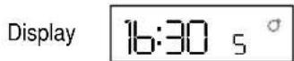
- Press button (P)

- The timer can be programmed with up to 8 ON and 8 OFF times by repeating the above procedure.
1.1 Use buttons + and - to set 1st ON time eg. 6:00
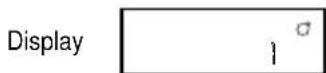
2.1 Use buttons + and - to set OFF time, eg. 9:00

3.1 Use button + and - to set 2nd ON time, eg. 12:30

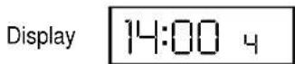
4.1 Use button + and - to set 2nd OFF time eg. 14:00
5.1 Use button + and - to set 3rd ON time, eg. 16:00

6.1 Use button + and - to set 3rd OFF time eg. 23:30
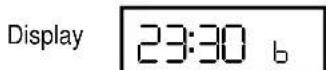
- On completion of programming slide switch (A) to Auto position, the time of day will be displayed and the central heating will switch ON and OFF according to the programme set.
Over ride
By pressing the over ride button (E) the timer programme is over ridden ie, if programme is in OFF time it will come ON and if in ON time will go OFF.
The timer will revert back to it set programme on reaching the next ON or OFF time.
When the programme is on over ride the sign ↔ will be shown in the display window (B).
Reset Button
By the use of a pencil the reset button can be pushed (R). This will clear all programmes apart from those factory pre set.
Reset is only possible with switch (A) in set Clock position!
IMPORTANT:
If the pump sticks, it can usually be freed by removing the chrome center screw, (a small amount of water will escape) and manually free the impeller using a screwdriver in the end of the shaft.
Phone numbers:
Installer ____
Service Engineer ____
BECAUSE OF OUR CONSTANT ENDEAVOUR FOR IMPROVEMENT DETAILS MAY VARY SLIGHTLY FROM THOSE QUOTED IN THESE INSTRUCTIONS.
ALL SPECIFICATIONS SUBJECT TO CHANGE
- WALL MOUNTED, ROOM SEALED, FAN ASSISTED, GAS COMBINATION BOILER
- USERS INSTRUCTIONS
- CONDITIONS OF INSTALLATION
- GAS SUPPLY
- ELECTRICAL SUPPLY 230 V \~ 50 HZ FUSED 3A
- MINIMUM CLEARANCE
- BOILER LIGHTING INSTRUCTIONS
- TO SHUT DOWN THE BOILER FOR SHORT PERIODS
- TO SHUT DOWN THE BOILER FOR LONG PERIODS
- BOILER CONTROLS
- 1.0 CENTRAL HEATING SELECTOR SWITCH
- 2.0 TIME CLOCK
- 3.0 BOILER THERMOSTAT TEMPERATURE SETTING (CENTRAL HEATING)
- 4.0 DOMESTIC HOT WATER
- 5.0 SERVICING
- GENERAL NOTES
- 1.0 ESPACE OF GAS
- 2.0 SYSTEM WATER PRESSURE
- 3.0 VENTILATION
- 4.0 FROST PROTECTION
- 5.0 HIGH LIMIT CUT-OFF THERMOSTAT
- SIMPLE CHECKS
- TIME CLOCK
- TO SET TIME OF DAY
- TO SET OWN ON AND OFF TIMES. SYMBOL ☐ IN DISPLAY = ON TIME
- OVER RIDE
- RESET BUTTON
- IMPORTANT
Brand : FERROLI
Model : Optima 901
Category : Central heating boiler