GZ-8201 - Cooker Guzzanti - Free user manual and instructions
Find the device manual for free GZ-8201 Guzzanti in PDF.


| Product Type | Freestanding Cooker |
| Brand | Guzzanti |
| Model | GZ-8201 |
| Energy Type | Gas Hob / Electric Oven |
| Number of Burners | 4 Gas Burners |
| Oven Type | Electric Conventional Oven |
| Oven Capacity | Approximately 70 Liters |
| Dimensions (H x W x D) | 85 x 50 x 60 cm |
| Weight | Approximately 50 kg |
| Power Supply | 230 V ~ 50 Hz |
| Gas Connection | G 1/2" Gas Inlet (LPG or Natural Gas) |
| Energy Class | A (Estimated) |
| Control Type | Knobs for Hob and Oven |
| Oven Functions | Top Heat, Bottom Heat, Grill |
| Cleaning Type | Easy-Clean Enamel Interior |
| Safety Features | Flame Failure Device on Burners |
| Thermostat | Oven Thermostat (50-250°C) |
| Timer | Mechanical Timer with Alarm |
| Interior Light | Yes |
| Spare Parts Availability | Authorized Service Centers |
| Guarantee | 2 Years (Subject to Terms) |
| Manual Languages | EN, CS, DE, HU, PL, SK, SL |
Frequently Asked Questions - GZ-8201 Guzzanti
User questions about GZ-8201 Guzzanti
0 question about this device. Answer the ones you know or ask your own.
Ask a new question about this device
Download the instructions for your Cooker in PDF format for free! Find your manual GZ-8201 - Guzzanti and take your electronic device back in hand. On this page are published all the documents necessary for the use of your device. GZ-8201 by Guzzanti.
USER MANUAL GZ-8201 Guzzanti
natural_image
Line drawing of a four-cylindrical electrical heating element with a base and mounting base (no text or symbols)Návod k obsluze Návod na obsluhu Instrukcja obsługi Használati útmutató Navodila za uporabo Gebrauchsanleitung Instruction manual
Vážený uživateli,
flowchart
graph TD
    A["Start"] --> B{Condition}
    B --> C["Step 1: Circle with arrow pointing to top node"]
    B --> D["Step 2: Circle with arrow pointing to top node"]
    B --> E["Step 3: Circle with arrow pointing to top node"]
    B --> F["Step 4: Circle with arrow pointing to top node"]
    B --> G["Step 5: Circle with arrow pointing to top node"]
Panel - varná plocha 70-90 cm a 100 cm
natural_image
Four identical diagrams showing circles with star and dot symbols, connected by curved lines (no text or labels)Panel - varná plocha 60 cm
natural_image
Three identical diagrams showing circles with arrows and dots, no text or symbols presentPanel - varná plocha 45 cm
NÁKRES ELEKTRICKÉHO ZAPOJENÍ
Pravda Lež Pravda Pravda
natural_image
Technical line drawing of a kitchen appliance with three burners and a control panel (no text or symbols)
natural_image
Pure diagram of a horizontal beam with two support points, no text or symbols presentObrázek 2
natural_image
Technical line drawings of a mechanical component with three views: top view, side view, and bottom view (no text or symbols)natural_image
Technical line drawing of a mechanical device with three circular components and a handle (no text or symbols)Obrázek 7
natural_image
Technical line drawing of an internal combustion engine component (no text or labels)Obrázek 8
PLYN - BEZPEČNOSTNÍ ZAŘÍZENÍ (FFD)
natural_image
Line drawing of a hand holding a circular object with directional arrows indicating movement (no text or symbols)natural_image
Illustration of a hand holding a circular object with motion lines indicating rotation (no text or symbols)natural_image
Line drawing of a hand holding a circular object with motion arrows indicating rotation (no text or symbols)natural_image
Four black-and-white illustrations of cooking pots with crossed marks, one being heated by a steaming pot (no text or symbols)natural_image
Technical line drawing of a mechanical component with concentric rings and mounting brackets (no text or symbols)Obrázek 12
natural_image
Illustration of a hand pressing down on a circular object with a small object inside (no text or symbols)Obrázek 13
natural_image
Technical line drawing of a mechanical component with concentric rings and a small inset view (no text or symbols)Obrázek 14
natural_image
Illustration of a hand using a tool to cut or mark a circular mechanical component (no text or symbols present)Obrázek 15
PROBLÉMY A NÁVRHY ŘEŠENÍ
natural_image
Symbol of a trash bin crossed with a diagonal line, no text or numbers presentnatural_image
Symbol of a trash bin crossed with no text or numbers, representing waste sorting or disposal (no text present)
flowchart
graph TD
    A["Start"] --> B{Condition}
    B --> C["Step 1: Circle with arrow pointing to top node"]
    B --> D["Step 2: Arrow pointing to top node with dot at center"]
    B --> E["Step 3: Circle with arrow pointing to top node"]
    B --> F["Step 4: Circle with arrow pointing to top node"]
    B --> G["Step 5: Circle with arrow pointing to top node"]
Panel - varná plocha 70-90 cm a 100 cm
natural_image
Four identical diagrams showing circles with star and dot symbols, connected by curved lines (no text or labels)Panel - varná plocha 60 cm
natural_image
Three identical diagrams showing circles with arrows and dots, no text or symbols presentPanel - varná plocha 45 cm
SCHÉMA ELEKTRICKÉHO PRIPOJENIA
natural_image
Technical line drawing showing a battery pack assembly with a magnified view of its internal components (no text or symbols present)
natural_image
Pure diagram of a horizontal beam with two support points, no text or symbols presentObrázok 2
natural_image
Technical line drawings of a mechanical component with three views: top view, side view, and bottom view (no text or symbols)natural_image
Technical line drawing of a mechanical device with three circular components and a handle (no text or symbols)Obrázok 7
natural_image
Technical line drawing of an engine or mechanical component with no visible text or symbolsObrázok 8
PLYN - BEZPEČNOSTNÉ ZARIADENIE (FFD)
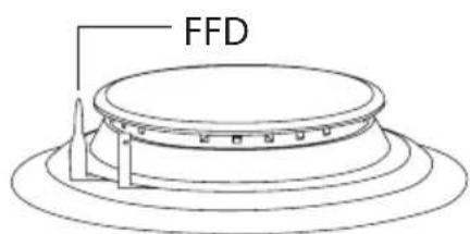
Pokial'dôjde k pretečeniu potravín na horáky, bezpečnostné zariadenie sa zapne a ihned' odpojí plyn.
POUŽITIE VARNÉHO PANELA
natural_image
Line drawing of a hand holding a circular object with directional arrows indicating movement (no text or symbols)natural_image
Line drawing of a hand holding a circular object with motion lines indicating rotation (no text or symbols)natural_image
Line drawing of a hand holding a circular object with motion arrows indicating rotation (no text or symbols)natural_image
Four black-and-white illustrations of cooking pots with checkmarks, no text or symbols presentnatural_image
Technical line drawing of a mechanical component with concentric rings and mounting brackets (no text or symbols)Obrázok 12
natural_image
Illustration of a hand pressing down on a circular object with a small object inside (no text or symbols)Obrázok 13
natural_image
Technical line drawing of a mechanical component with concentric rings and a small inset view (no text or symbols)Obrázok 14
natural_image
Illustration of a hand using a tool to cut or mark a circular mechanical component (no text or symbols present)Obrázok 15
PROBLÉMY A MOŽNOSTÍ RIEŠENIA
natural_image
Symbol of a trash bin crossed with a diagonal line, no text or numbers presentnatural_image
Symbol of a trash bin crossed with no text or numbers, representing waste sorting or disposal (no text present)
flowchart
graph TD
    A["Start"] --> B{Condition}
    B --> C["Step 1: Circle with arrow"]
    B --> D["Step 2: Circle with arrow"]
    B --> E["Step 3: Circle with arrow"]
    B --> F["Step 4: Circle with arrow"]
    B --> G["Step 5: Circle with arrow"]
Panel - strefa grzewcza 70-90 cm i 100 cm
natural_image
Four identical diagrams showing circular shapes with star and circle symbols, each connected by curved lines (no text or labels)natural_image
Three identical diagrams showing circles with arrows and dots, no text or symbols presentnatural_image
Technical line drawing of a kitchen appliance with three burners and a control panel (no text or symbols)
natural_image
Simple line drawing of a horizontal beam with two supports at both ends (no text or symbols)Rysunek 2
natural_image
Technical line drawings of a mechanical component with three views: top view, side view, and bottom view (no text or symbols)natural_image
Technical line drawing of a mechanical device with three cylindrical components and a handle (no text or symbols)Rysunek 7
natural_image
Technical line drawing of a mechanical assembly with no visible text or symbolsRysunek 8
GAZ - URZĄDZENIE ZABEZPIECZAJĄCE (FFD)
natural_image
Line drawing of a hand holding a circular object with directional arrows indicating motion (no text or symbols)natural_image
Line drawing of a hand holding a circular object with motion lines indicating rotation (no text or symbols)natural_image
Hand holding a circular object with directional arrows indicating rotation (no text or symbols)natural_image
Four black-and-white illustrations of cooking pots with checkmarks, no text or symbols presentnatural_image
Technical line drawing of a mechanical component with concentric rings and mounting brackets (no text or symbols)Rysunek 12
| POZIOM1 | POZIOM2 | POZIOM3 | POZIOM4 | POZIOM5 | POZIOM6 | |
| ∅ 80 mm 200 W 250 | W 450 W --- --- | --- | ||||
| ∅ 145 mm 250 W 750 | W 1000 W --- --- | --- | ||||
| ∅ 180 mm 500 W 750 | W 1500 W --- --- | --- | ||||
| ∅ 145 mm szybki 500 | W 1000 W 1500 | W --- --- --- | ||||
| ∅ 180 mm szybki 850 | W 1150 W 2000 | W --- --- --- | ||||
| ∅ 145 mm 95 W 155 | W 250 W 400 W | 750 W 1000 W | ||||
| ∅ 180 mm 115 W 175 | W 250 W 600 | W 850 W 1500 W | ||||
| ∅ 145 mm szybki 135 | W 165 W 250 | W 500 W 750 W | 500 W | |||
| ∅ 180 mm szybki 175 | W 220 W 300 | W 850 W 1150 W | 2000 W |
KONSERWACJA I CZYSZCZENIE
natural_image
Illustration of a hand pressing down on a circular object with a small object inside (no text or symbols)Rysunek 13
natural_image
Simple line drawing of a mechanical component with a circular base and top view (no text or symbols)Rysunek 14
natural_image
Illustration of a hand using a tool to clean or inspect a circular mechanical component (no text or symbols visible)Rysunek 15
PROBLEMY I ICH ROZWIĄZYWANIE
natural_image
Symbol of a trash bin crossed with no text or numbers, representing environmental restriction (no text present)natural_image
Symbol of a trash bin crossed with no text or numbers, representing waste sorting or disposal (no text present)
flowchart
graph TD
    A["Start"] --> B{Condition}
    B --> C["Step 1: Circle with arrow pointing to top node"]
    B --> D["Step 2: Circle with arrow pointing to top node"]
    B --> E["Step 3: Circle with arrow pointing to top node"]
    B --> F["Step 4: Circle with arrow pointing to top node"]
    B --> G["Step 5: Circle with arrow pointing to top node"]
natural_image
Four identical diagrams showing circles with star and dot symbols, connected by curved lines (no text or labels)natural_image
Three identical diagrams showing circles with arrows and dots, no text or symbols presentnatural_image
Technical line drawing of a kitchen appliance with three burners and a control panel (no text or symbols)
natural_image
Simple line drawing of a horizontal beam with two supports at both ends (no text or symbols)natural_image
Technical line drawing of a mechanical component with three circular parts and a handle (no text or symbols)- ábra
natural_image
Technical line drawing of a mechanical assembly with no visible text or symbols- ábra
GÁZ - BIZTONSÁGI BERENDEZÉS (FFD)
natural_image
Line drawing of a hand holding a circular object with directional arrows indicating movement (no text or symbols)natural_image
Illustration of a hand holding a circular object with motion lines indicating rotation (no text or symbols)natural_image
Hand holding a circular object with motion arrows indicating rotation (no text or symbols)natural_image
Four black-and-white illustrations of cooking pots with crossed marks, showing different cooking methods (no text or symbols)natural_image
Technical line drawing of a mechanical component with concentric rings and mounting brackets (no text or symbols)- ábra
| 1. SZINT 2. SZINT 3. SZINT 4. SZINT 5. SZINT 6. SZINT | ||||||
| ∅ 80 mm 200 W 250 | W 450 W --- --- | |||||
| ∅ 145 mm 250 W 750 | W 1000 W --- --- | |||||
| ∅ 180 mm 500 W 750 | W 1500 W --- --- | |||||
| ∅ 145 mm gyors 50 | W 1000 W 1500 | W --- --- --- | ||||
| ∅ 180 mm gyors 85 | W 1150 W 2000 | W --- --- --- | ||||
| ∅ 145 mm 95 W 155 | W 250 W 400 W | 750 W 1000 W | ||||
| ∅ 180 mm 115 W 175 | W 250 W 600 | W 850 W 1500 W | ||||
| ∅ 145 mm gyors 135 | W 165 W 250 W | 500 W 750 W 1500 W | ||||
| ∅ 180 mm gyors 175 | W 220 W 300 W | 850 W 1150 W 2000 W | ||||
ÁPOLÁS ÉS TISZTÍTÁS
natural_image
Illustration of a hand pressing down on a circular object with a small object inside (no text or symbols)- ábra
natural_image
Simple line drawing of a mechanical component with a circular base and top view (no text or symbols)- ábra
natural_image
Illustration of a hand using a tool to adjust or install a circular component (no text or symbols visible)natural_image
Symbol of a trash bin crossed with a diagonal line, no text or numbers presentnatural_image
Symbol of a trash bin crossed with no text or numbers, representing waste sorting or restriction (no text present)
natural_image
Three identical diagrams showing circles with arrows and dots, no text or symbols presentPlošča - kuhalna površina 45 cm
SHEMA ELEKTRIČNE PRIKLJUČITVE
natural_image
Technical line drawing of a kitchen appliance with three burners and a control panel (no text or symbols)
natural_image
Simple line drawing of a horizontal beam with two supports at both ends (no text or symbols)Slika 2
natural_image
Technical line drawing of a mechanical component with no visible text or symbols4
natural_image
Diagram of a mechanical device with rotating components and a central shaft (no text or symbols)Slika
5
Sli
natural_image
Technical line drawing of a mechanical component with three cylindrical parts and a handle (no text or symbols)Slika 7
natural_image
Technical line drawing of a mechanical assembly with no visible text or symbolsSlika 8
PLIN - VARNOSTNA NAPRAVA (FFD)
Če hrana prekipi na gorilnike, se vklopi varnostna naprava in takoj odklopi plin.
UPORABA KUHALNE PLOŠČE
natural_image
Line drawing of a hand holding a circular object with directional arrows indicating motion (no text or symbols)natural_image
Line drawing of a hand holding a circular object with motion lines indicating rotation (no text or symbols)natural_image
Line drawing of a hand holding a circular object with motion arrows indicating rotation (no text or symbols)Želeno dolžino plamena nastavite tako, da pritiskate na gumb in zavrtite na desno.
natural_image
Four black-and-white illustrations of cooking pots with checkmarks, no text or symbols presentnatural_image
Technical line drawing of a mechanical component with concentric rings and mounting brackets (no text or symbols)Slika 12
| MOČ GRETJA 1 | MOČ GRETJA 2 | MOČ GRETJA 3 | MOČ GRETJA 4 | MOČ GRETJA 5 | MOČ GRETJA 6 | |
| ∅ 80 mm 200 W 250 | W 450 W --- --- | |||||
| ∅ 145 mm 250 W 750 | W 1000 W --- --- | |||||
| ∅ 180 mm 500 W 750 | W 1500 W --- --- | |||||
| ∅ 145 mm hitro 500 | W 1000 W 1500 | W --- --- --- | ||||
| ∅ 180 mm hitro 850 | W 1150 W 2000 | W --- --- --- | ||||
| ∅ 145 mm 95 W 155 | W 250 W 400 W | 750 W 1000 W | ||||
| ∅ 180 mm 115 W 175 | W 250 W 600 | W 850 W 1500 W | ||||
| ∅ 145 mm hitro 135 | W 165 W 250 W | 500 W 750 W 1500 W | ||||
| ∅ 180 mm hitro 175 | W 220 W 300 W | 850 W 1150 W 2000 W |
VZDRŽEVANJE IN ČIŠČENJE
natural_image
Illustration of a hand pressing down on a circular object with a small object inside (no text or symbols)Slika 13
natural_image
Simple line drawing of a mechanical component with a circular base and top view (no text or symbols)Slika 15
natural_image
Illustration of a hand using a tool to adjust or install a circular mechanical component (no text or symbols visible)MOREBITNE TEŽAVE IN REŠITVE
natural_image
Symbol of a trash bin crossed with no text or numbers, representing environmental restriction (no text present)- Embalažo odstranite na okolju prijazen način.
- Ta naprava je označena v skladu z Evropsko direktivo 2002/96/ES o odpadni električni in elektronski opremi (waste electrical and electronic equipment - WEEE). Direktiva določa okvir za zbiranje in recikliranje rabljenih aparatov, ki velja po vsej EU.
INFORMACIJE O EMBALAŽI
natural_image
Symbol of a trash bin crossed with no text or numbers, representing environmental protection (no text present)natural_image
Four identical diagrams showing circular shapes with star and circle symbols, connected by curved lines (no text or labels)Bedienfeld - Kochfeld 60 cm
natural_image
Three identical diagrams showing circles with arrows and dots, no text or symbols presentBedienfeld - Kochfeld 45 cm
ENTWURF DES STROMANSCHLUSSES
natural_image
Technical line drawing showing a battery pack assembly with a magnified inset view (no text or symbols)
natural_image
Pure diagram of a horizontal beam with two supports at both ends, no text or symbols presentAbbildung 2
natural_image
Technical line drawings of a mechanical component with three views: top view, side view, and bottom view (no text or symbols)natural_image
Technical line drawing of a mechanical component with three cylindrical parts and a lever (no text or symbols)Abbildung 7
natural_image
Technical line drawing of a mechanical assembly with no visible text or symbolsAbbildung 8
natural_image
Line drawing of a hand holding a circular object with directional arrows indicating motion (no text or symbols)natural_image
Line drawing of a hand holding a finger with motion lines indicating rotation (no text or symbols)natural_image
Hand holding a circular object with motion arrows indicating rotation (no text or symbols)natural_image
Technical line drawing of a mechanical component with concentric rings and mounting brackets (no text or symbols)Abbildung 12
| STUFE 1 STUFE 2 STUFE 3 STUFE 4 STUFE 5 STUFE 6 | ||||||
| ∅ 80 mm 200 W 250 | W 450 W --- --- | |||||
| ∅ 145 mm 250 W 750 | W 1000 W --- --- | |||||
| ∅ 180 mm 500 W 750 | W 1500 W --- --- | |||||
| ∅ 145 mm schnell | 500 W 1000 W 1500 W --- --- --- | |||||
| ∅ 180 mm schnell | 850 W 1150 W 2000 W --- --- --- | |||||
| ∅ 145 mm 95 W 155 | W 250 W 400 W 750 W 1000 W | |||||
| ∅ 180 mm 115 W 175 | W 250 W 600 W 850 W 1500 W | |||||
| ∅ 145 mm schnell | 135 W 165 W 250 | W 500 W 750 W 1500 W | ||||
| ∅ 180 mm schnell | 175 W 220 W 300 | W 850 W 1150 W 2000 W | ||||
natural_image
Illustration of a hand pressing down on a circular object with a small object inside (no text or symbols)Abbildung 13
natural_image
Technical line drawing of a mechanical component with concentric rings and a small inset view (no text or symbols)Abbildung 14
natural_image
Illustration of a hand using a tool to cut or mark a circular mechanical component (no text or symbols present)Abbildung 15
natural_image
Symbol of a trash bin crossed with no text or numbers, representing environmental restriction (no text present)natural_image
Symbol of a trash bin crossed with no text or numbers, representing waste sorting or disposal (no text present)
Our objective is to make this product provide you with the best output which is manufactured in our modern facilities in a careful working environment, in compliance with total quality concept.
Therefore, we suggest you to read the user manual carefully before using the product and, keep it permanently at your disposal.
Note: This user manual is prepared for more than one model. Some of the features specified in the Manual may not be available in your appliance.
All our appliances are only for domestic use, not for commercial use.
"Conforms with the WEEE Regulations."
CONTENTS
IMPORTANT WARNINGS 4
INTRODUCTION OF THE APPLIANCE 5
CONTROL PANEL....6
IMPORTANT WARNINGS....7
IF BUILT-IN OVEN IS PLACED UNDER COOKTOP 9
INSTALLATION OF COOKSTOP 9
COUNTER CUTTING SIZES AND INSTALLATION OF YOUR COOKTOP 11
CORRECT PLACE FOR INSTALLATION 12
VENTILATION OF ROOM 12
TRANSFORMATION FROM NATURAL GAS TO LPG AND FROM LPG 13
TO NATURAL GAS 13
GAS BREAKING SAFETY APPLIANCE (FFD)....13
USAGE OF YOUR COOKTOP 14
POT DIAMETER 15
WOK BURNER....15
USAGE OF HOTPLATE 16
MAINTENANCE AND CLEANING....16
ROUBLES AND SOLUTION PROPOSALS....17
ENVIRONMENTALLY-FRIENDLY DISPOSAL....19
PACKAGE INFORMATION.... 19
- WARNING: Before touching the connection terminals, all supply circuit should be disconnected.
- WARNING: Any inadvertent cooking made with fats and oils can be dangerous and cause fire.
- WARNING: Risk of fire; do not store the food materials on the cooking surface.
- WARNING: During usage the reachable sections can be hot. Keep the small children away.
- WARNING: The appliance and its reachable sections become hot during usage.
- The setting conditions of this appliance is indicated on the label. (Or data tag)
- This appliance is not connected to a combustion product discharge system. This appliance shall be connected and installed as per the applicable installation legislation. Consider the requirements related with ventilation.
- Using a gas hob will release humidity and combustion products in the room where it resides. Especially during when the appliance in use, ensure that the kitchen is well ventilated and retain the natural ventilation holes or install a mechanical ventilation system. (Hood on top of the oven) Sustained usage of the appliance may require additional ventilation. For example opening a window or if available, increasing the ventilation level of a mechanical ventilation system.
- WARNING: The appliance is intended for cooking only. It must not be used for other purposes like room heating.
- This appliance should be installed as per regulations and in well-ventilated location only. Read the instructions before installing or operating the appliance."
- Before placing the appliance check the local conditions (gas type and gas pressure) and ensure that the settings of the appliance is appropriate.
- These instructions are applicable for countries of which symbols are indicated on the appliance. If the country symbol is not available on the appliance, in order to adapt the appliance to the conditions of such country, the technical instructions should be read."
- Do not operate the system for more that 15 seconds. If the burner does not ignite at the end of 15 seconds stop the operation of the system and open the section door and/or wait for at least 1 minute before igniting the burner.
- Do not use steam cleaners to clean the appliance.
- NEVER try to extinguish a fire with water, first disconnect the mains supply and then using, for example a lid or blanket, cover the fire.
- Unless continuous supervision is provided, the children of age 8 or below should be kept away.
- Pay attention for not to touch the heating elements.
- This appliance can be used by children aged from 8 years and above and persons with reduced physical, sensory or mental capabilities or lack of experience and knowledge if they have been given supervision or instruction concerning use of the appliance in a safe way and understand the hazards involved.
INTRODUCTION OF THE APPLIANCE
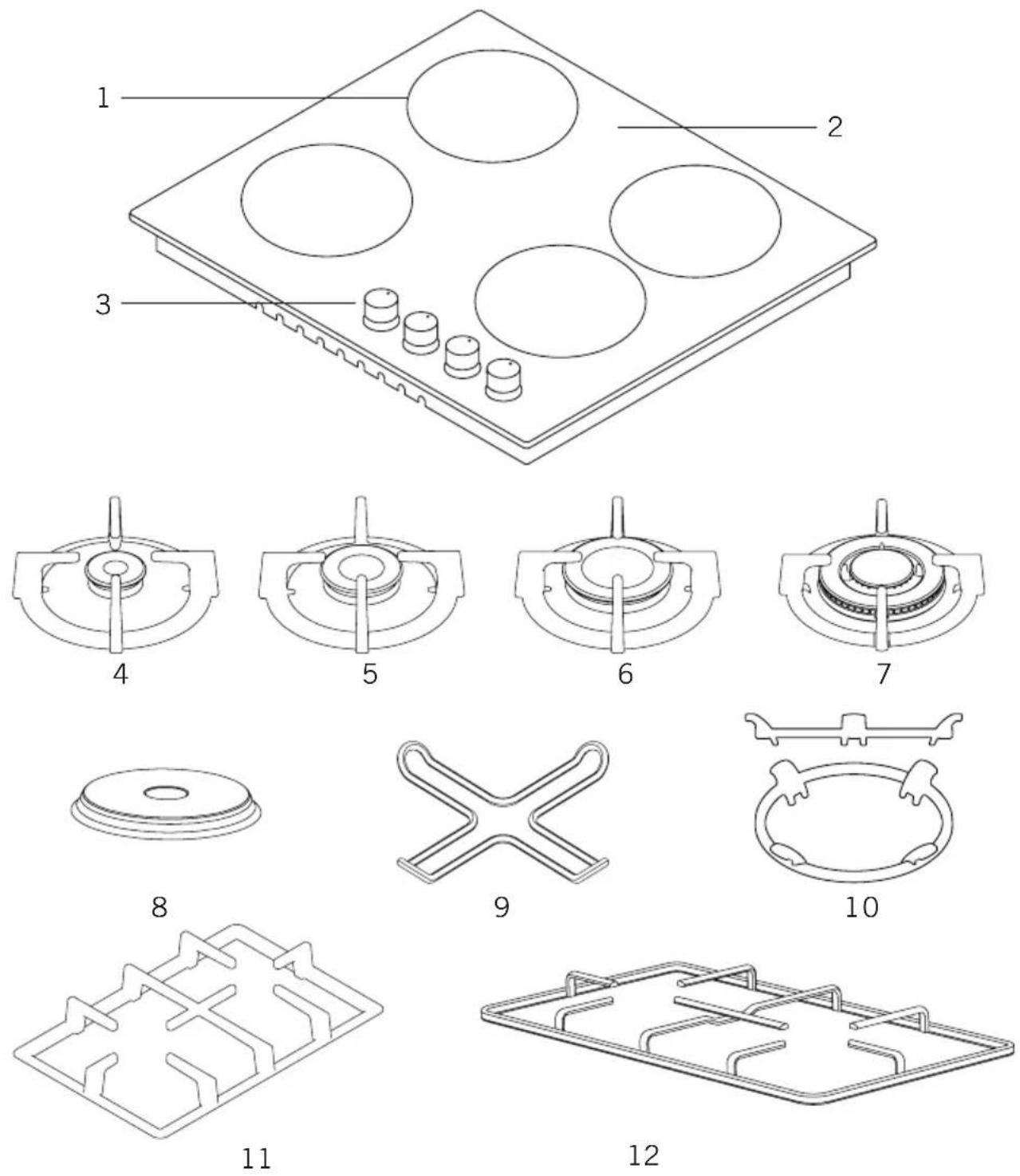
1- Burner positions
2- Glass or Metal Surface
3- Control Buttons
4- Small Burner
5- Medium Burner
6- Large Burner
7- WOK Burner
8- Hotplate
9- Coffee Adaptor
10- Wok Burner Adaptor
11- Cast Grill
12- Enamel Grill
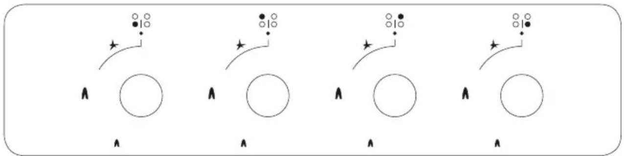
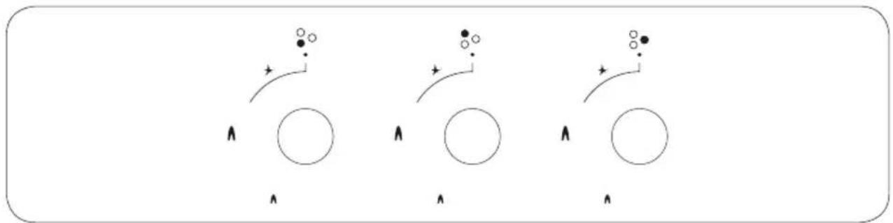
CONTROL PANEL
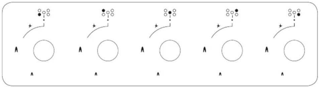
flowchart
graph TD
    A["Start"] --> B{Condition}
    B --> C["Step 1: Circle with arrow"]
    C --> D["Step 2: Circle with arrow"]
    D --> E["Step 3: Circle with arrow"]
    E --> F["Step 4: Circle with arrow"]
    F --> G["Step 5: Circle with arrow"]
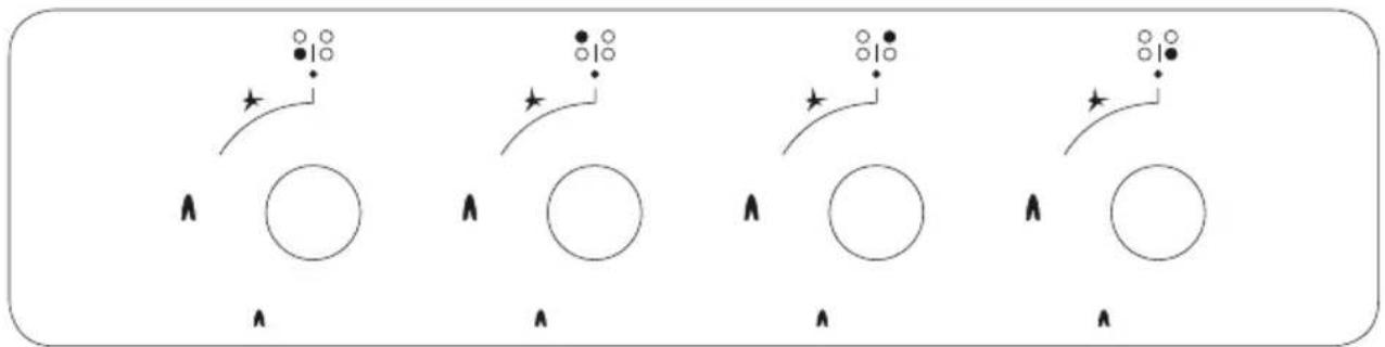
Cooktop Panel Visual of 70-90 cm and 100 cm
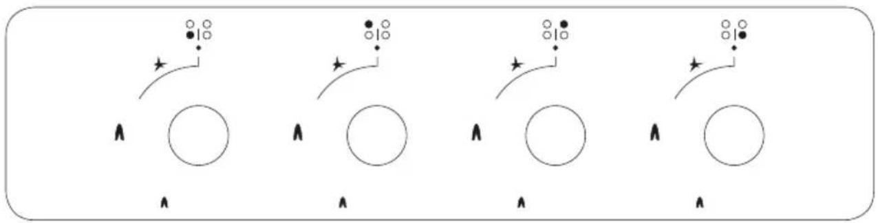
natural_image
Four identical diagrams showing circular shapes with star and circle symbols, connected by curved lines (no text or labels)Cooktop Panel Visual of 60 cm
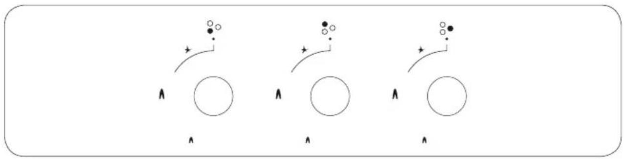
natural_image
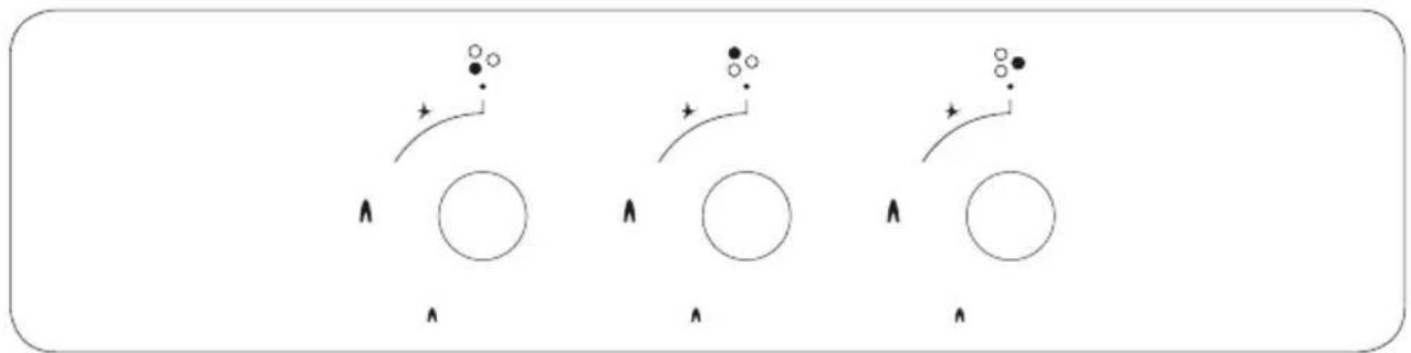
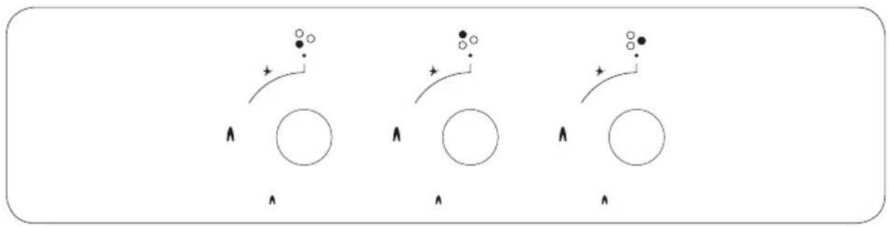
Three identical diagrams showing circles with arrows and dots, no text or symbols presentCooktop Panel Visual of 45 cm
ELECTRICAL CONNECTION SCHEME
Get electrical connection of your appliance done to authorized person in line with the following scheme.
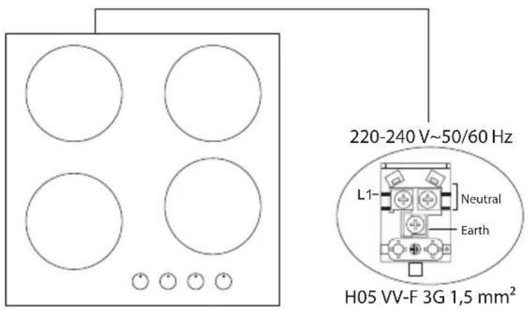
Electrical Connection and Safety
- Setting conditions of this appliance is indicated in tag or data plate.
- This appliance is not connected to any discharging apparatus of burning products. It should be connected and installed according to applicable assembly regulation.
- Great attention should be paid on ventilation related conditions.
- Your appliance should be connected to an appropriate fuse according to electric power. If necessary, it is recommended that connection is made by authorized service.
- Your appliance is configured in accordance with electrical supply of 220-240V, 50/60Hz.
- If main electrical network is different from these values, contact with your authorized service.
- Electrical connections of your appliance should only be made to the fuses having suitably wired grounding (grounded) system. If no convenient fuse is available in the place where your appliance is to be installed, contact with authorized service immediately. Manufacturing firm is not responsible definitely for the damages that fuses whose grounding is not made and connected to the appliance can cause.
- Plug of the appliance should be close to be accessed easily to the fuse whose grounding is made without use of extension cord.
- Do not allow contacting the power cable of your appliance with hot regions. Similarly, keep away it from sharp edges and corners.
- If feeder cord is damaged, this cord should be replaced either by manufacturer or its service agency or same degree qualified personnel in order to hinder a dangerous situation.
- Wrong electrical connection may give damage to the appliance. In this case, your appliance will remain out of guarantee scope. Electrical connection of your appliance should be done by authorized service.
- During operation of cooktop, some parts may be hot. When you also bring switches closed position, it may remain hot for a while. Children should be kept away every time and not be left without observation. Do not touch surface of cooktop while warning lights flashes. When you bring your appliance closed position, hot parts being still dangerous are stated with warning lights. (Vitroceran models)
Gas Connection and Safety
- For LPG (cylinder) connection, affix metal clamp on the hose coming from LPG cylinder. Affix an edge of the hose on hose inlet connector behind the appliance by pushing to end through heating the hose in boiled water. Afterward, bring the clamp towards end section of the hose and tighten it with screwdriver. The gasket and hose inlet connector required for connection is as the picture shown below.
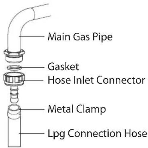
NOTE: The regulator to be affixed on LPG cylinder should have 300 mmSS feature.
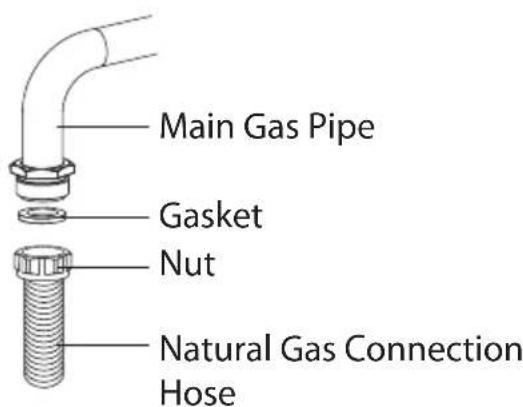
- Natural gas connection should be done by authorized service. For natural gas connection, place gasket in the nut at the edge of natural gas connection hose. To install the hose on main gas pipe, turn the nut. Complete the connection by making gas leakage control.

Gas hose and electric connection of the appliance should not pass next to hot areas such as back of the appliance. Gas hose should be connected by making wide angle turns against breaking possibility. Movement of appliance whose gas connection is made may cause gas leakage.
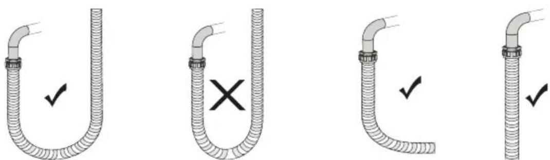
True False True True
- Connect your appliance to gas cock from the shortest way and in a manner to prevent any leakage. For safety, the hose used should be maximum 125 cm and minimum 40 cm.
- While making gas leakage control; never use lighter, match, glowing cigarette or similar inflammable matter.
- Apply soap bubble on connection point. If any leak/leakage exists, foaming will occur on soaped region.
- If the cooktop is to be mounted on a cabinet or openable drawer, a heat protection panel having 15 mm minimum opening should be mounted under the cooktop.
IF BUILT-IN OVEN IS PLACED UNDER COOKTOP
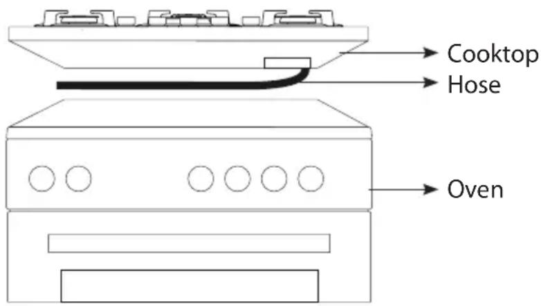
Figure 1
Gas pipe should be affixed in a way not to touch the oven below, sharp edges and corners, not to be pulled in a manner to be twisted and strained. Make gas connection from right part of the cooktop, fasten the hose by use of clamp.
INSTALLATION OF COOKSTOP
- Detach the burners, burner hoods and grills from the product.
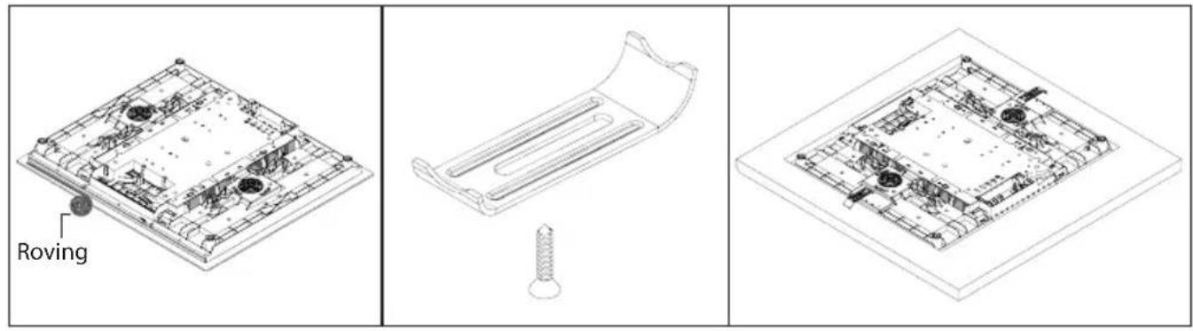
- Turn the cooktop down and place on smooth ground.
- In order to prevent entrance of foreign substances and liquids between cooktop and counter, apply the paste given in package to the sides of lower guard of counter. For corners, curl paste and increase curls till filling corner gaps.
- Turn cooktop again and align with and place on counter.
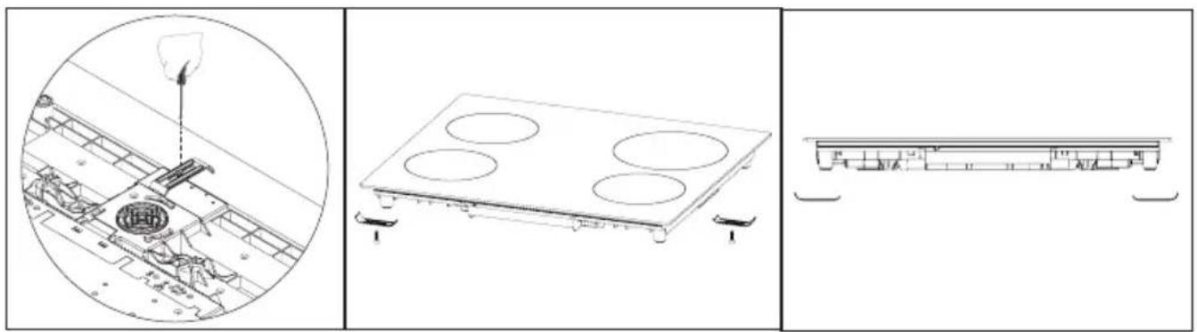
- Fasten up your cooktop on counter by using the clamp and screws supplied.
On the assembly chart given in next page, it is shown how to assemble your cooktop.
natural_image
Technical line drawing showing a battery pack assembly with a magnified view of its internal components (no text or symbols present)
natural_image
Simple line drawing of a horizontal beam with two supports at both ends (no text or symbols)Figure 2
- When product is mounted on a drawer, if it is possible to touch lower side of product, this section should be separated with a wooden shelf.

- While mounting cooktop on a closet, as shown in the figure above, in order to separate between closet and cooktop, a shelf should be mounted. If it is mounted on a built-in oven, there is no need to do that.
- If your cooktop will be mounted next to right or left wall, the minimum distance between wall and cooktop should be 50 mm.
COUNTER CUTTING SIZES AND INSTALLATION OF YOUR COOKTOP
Pay attention to the drawings and dimensions given below while making cooktop installation and adjusting counter cutting sizes.
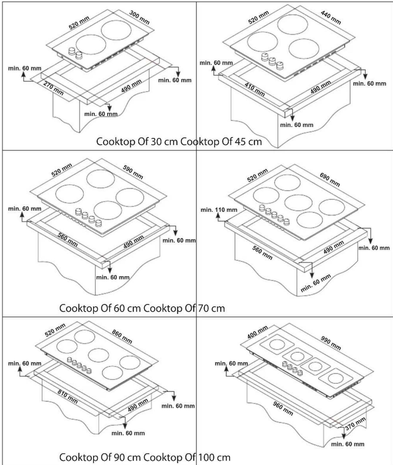
CORRECT PLACE FOR INSTALLATION
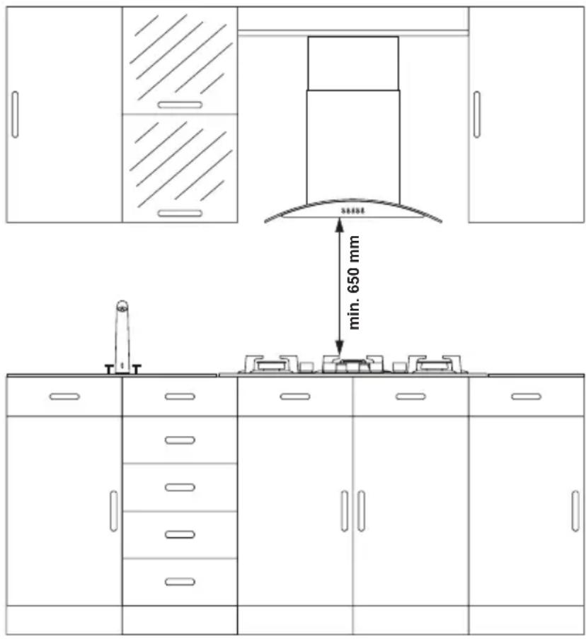
Product is designed in accordance with the kitchen counters supplied from market. A safe distance should be left between the product and kitchen walls and furniture.
If hood/aspirator will be installed over your appliance, obey to the recommendation of hood/aspirator manufacturer for assembly height. (min. 65 cm)
The gap that cooktop is to be placed on the counter should be cut in line with cooktop installation dimensions.
For installation of the product, the rules specified in local standards related to electricity should be complied.
VENTILATION OF ROOM
The air needed for burning is received from room air and the gases emitted are given directly in room. For safe operation of your product, good room ventilation is a precondition. If no window or room to be utilized for room ventilation is available, additional ventilation should be installed. However, room has a door opening outside, it is no needed to vent holes.
| Room Size Ventilating Opening | |
| Smaller than 5m^3 min. 100 cm^2 | |
| Between 5 m^3 - 10 m^3 min. 50 cm^2 | |
| Bigger than 10m^3 no need | |
| In basement or cellar min. 65 cm^2 | |
TRANSFORMATION FROM NATURAL GAS TO LPG AND FROM LPG TO NATURAL GAS
- Turn off gas and electricity of the cooktop. If your cooktop is hot, wait for cooling down.
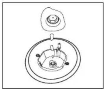
- For injector change, use a screwdriver whose edge is as the Figure 4.
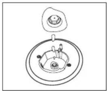
- As seen in Figure 5, demount burner lid and burner of the cooktop and ensure visibility of injector.
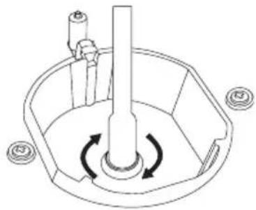
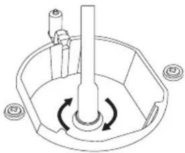
- Remove injector by turning as shown in Figure 6 with screwdriver and replace it with a new one.
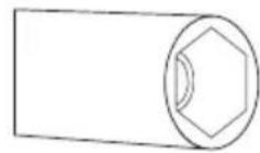
Figure
4
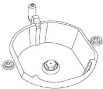
natural_image
Technical line drawing of a mechanical component with no visible text or symbolsFigure
natural_image
Diagram of a mechanical device with rotating components and a central shaft (no text or symbols)5
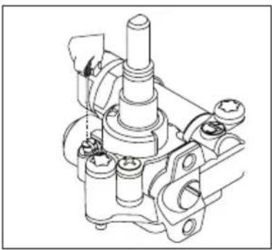
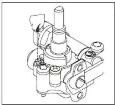
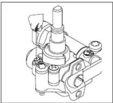
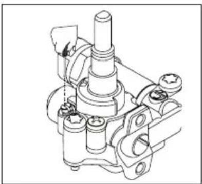
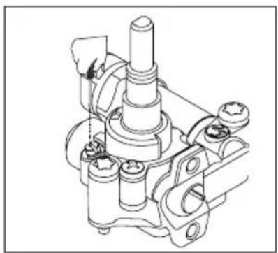
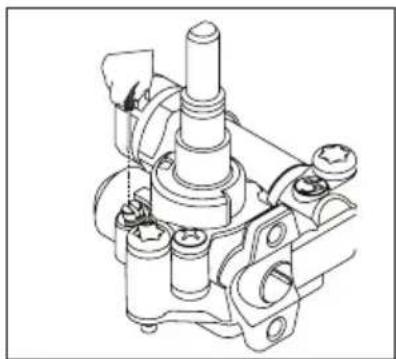
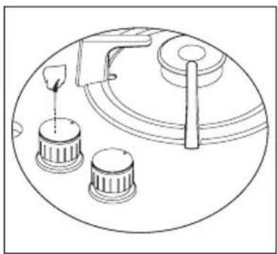
- After that, detach control switches of the cooktop. Make setting by turning the screw in the middle of gas cocks with a small screwdriver in the manner shown in the following picture. To adjust flow rate screw, use a screwdriver having suitable dimension. For LPG, turn the screw clockwise. For natural gas, turn the screw one time counter clockwise. At low position, length of normal flame should be 6-7 mm. For the last control, check out whether flame is open or closed. Setting of your appliance may differ according to the type of gas cock used.
natural_image
Diagram of a mechanical device with three circular components and a handle, no text or symbols presentFigure 7
natural_image
Technical line drawing of a mechanical assembly with no visible text or symbolsFigure 8
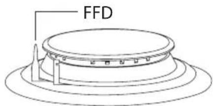
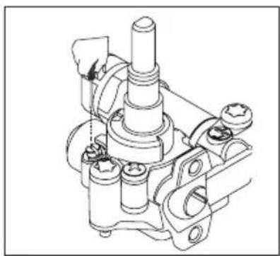
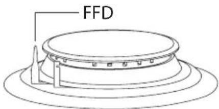
GAS BREAKING SAFETY APPLIANCE (FFD)
Against putting out to be taken place as a result of liquid overflow at upper burners, safety appliance steps in and cut gas immediately.
USAGE OF YOUR COOKTOP
Usage of Gas Cooktop
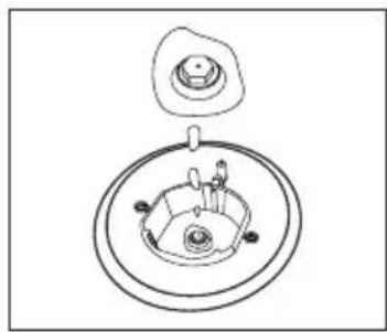
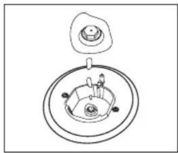
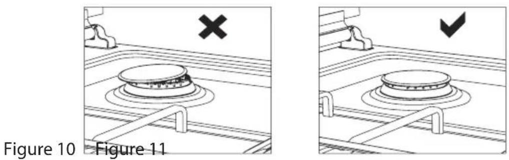
- Before starting to use your cooktop, be sure burner hoods are at correct position. Correct placement of burner hoods are shown in the following figure.
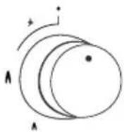
- Gas cocks have a special locking mechanism. Therefore, to operate cooktop zone, press button by pushing ahead and while opening or closing the cock, hold down the button.
- Closed
Fully open
Half open
- For automatic igniting models, igniting is realized via electricity. Therefore, before operating appliance, be sure that appliance has electric connection. Igniting for these models is as follows.
Cooktop cock is at closed position.
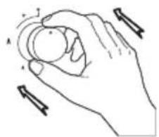
natural_image
Line drawing of a hand holding a circular object with directional arrows indicating movement (no text or symbols)To ignite cooktop, firstly press the button towards ahead.
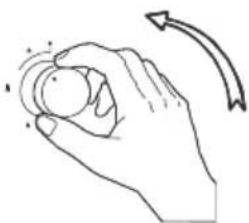
natural_image
Line drawing of a hand holding a circular object with motion lines indicating rotation (no text or symbols)While holding down the button, lighter steps in and starts to ignition.
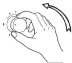
natural_image
Hand holding a circular object with motion arrows indicating rotation (no text or symbols)By turning the button right while holding down, you can provide ignition at flame length you want.
- Pay attention that cooktop grills are placed on cooktop table completely. In case of failure about this matter can cause pouring of the materials to be put on that.
-
For the models having gas putting out safety, following realizing ignition procedure according to the guidelines above, wait for 5-10 seconds by pushing button ahead without keeping your hands off. Safety mechanism will step in this duration and ensures operation of the cooktop. With regard to gas putting out appliance, gas cock cuts the gas going to cooktop zone in case of putting out of cooktop flame due to any reason.
-
While using coffee pot apparatus supplied along with the cooktop, be sure that foots of apparatus are placed on cooktop grill exactly and remain on cooktop zone in centred way. Use the apparatus only on small burner.
- While utilizing gas cooktops, use saucepan, placed on cooktop surface as far as possible. Thanks to that, you can save energy. In the following table, cooking pot diameters recommended to be used as per burners are given. Characteristic of Wok cooktop zone is to cook quickly.
POT DIAMETER
| GLASS HOBS | ||||||
| Domino | 45 cm. Hobs | 60 cm. Hand Control | 60 cm. Control Front | 70 cm. Control Front | 90 cm. Control Front | |
| Small Burner 12-18 | cm 12-18 cm 1 | 2-18 cm 12-18 cm | m 12-18 cm 12-18 cm | |||
| Middle Burner --- | 18-20 cm 18-20 cm | 18-20 cm 18-20 cm | 20 cm 18-22 cm | |||
| Big Burner 18-24 cm | 22-24 cm 22-24 cm | 24 cm 22-24 cm | 22-24 cm 22-26 cm | |||
| Wok Burner 24-26 cm | --- 24-26 cm | 24-26 cm 24-26 cm | 26-30 cm | |||
| METAL HOBS | ||||||
| Domino | 45 cm. Hobs | 60 cm. Hand Control | 60 cm. Control Front | 70 cm. Control Front | 90 cm. Control Front | |
| Small Burner 12-18 | cm 12-18 cm 1 | 2-18 cm 12-18 cm | 12-18 cm 12-18 cm | 8 cm | ||
| Middle Burner --- | 18-20 cm 18-20 cm | 18-20 cm 18-20 cm | 20 cm 18-22 cm | |||
| Big Burner 18-22 cm | 22-24 cm 22-24 cm | 26 cm 22-24 cm | 22-24 cm 22-26 cm | |||
| Wok Burner 24-26 cm | 24-26 cm 24-26 cm | 24-26 cm 24-26 cm | 24-26 cm 26-32 cm | |||
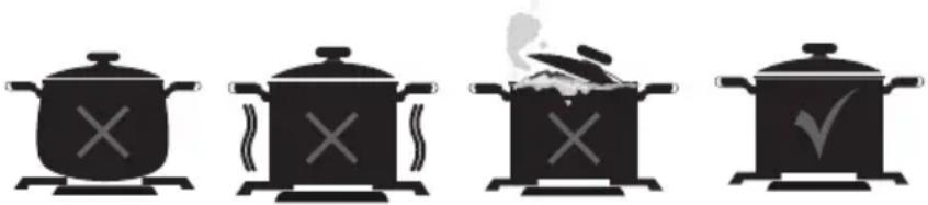
natural_image
Four black-and-white illustrations of cooking pots with cooking utensils, no text or symbols presentFalse False False True
Cooking pot to be used with products should have minimum 120 mm. diameter.
WOK BURNER
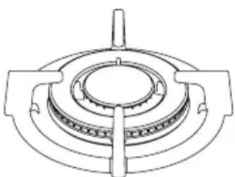
natural_image
Technical line drawing of a mechanical component with concentric rings and mounting brackets (no text or symbols)Figure 12
As it possesses double ring flame system, it gives homogenous heat distribution at the bottom of cooking pot at high temperature. It is ideal for short term and high temperature cooking. When you want to use regular cooking pot on wok burner, it is necessary that you remove wok cooking pot carrier from cooktop.
USAGE OF HOTPLATE
You can operate electric cooktops by turning the button on control panel you want to use to the level you desire. Cooktop powers as per levels are given in the following table.
| LEVEL 1 LEVEL 2 LEVEL 3 LEVEL 4 LEVEL 5 LEVEL 6 | ||||||
| ∅ 80 mm 200 W 250 | W 450 W --- --- | |||||
| ∅ 145 mm 250 W 750 | W 1000 W --- --- | |||||
| ∅ 180 mm 500 W 750 | W 1500 W --- --- | |||||
| ∅ 145 mm Rapid 500 | W 1000 W 1500 | W --- --- --- | ||||
| ∅ 180 mm Rapid 850 | W 1150 W 2000 | W --- --- --- | ||||
| ∅ 145 mm 95 W 155 | W 250 W 400 W | 750 W 1000 W | ||||
| ∅ 180 mm 115 W 175 | W 250 W 600 | W 850 W 1500 W | ||||
| ∅ 145 mm Rapid 135 | W 165 W 250 | W 500 W 750 W 1500 W | ||||
| ∅ 180 mm Rapid 175 | W 220 W 300 | W 850 W 1150 W | 2000 W | |||
MAINTENANCE AND CLEANING
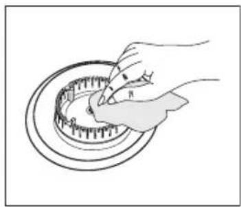
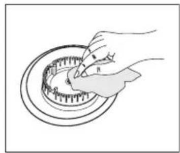
Before starting to maintenance or cleaning, firstly unplug the plug supplying electricity to cooktop and turn off gas valve. If cooktop is hot, wait for cooling down.
- For the purpose that your cooktop has long and economic life, regular cleaning and maintenance should be performed on your cooktop.
- Do not clean your cooktop with scratching tools such as bristle brush, wire wool or knife. Do not use abrasive, scratching, acid materials or detergent.
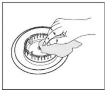
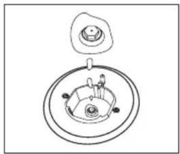
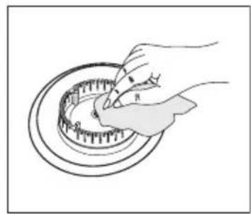
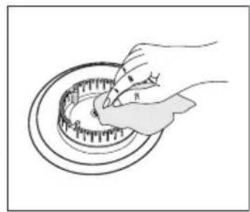
- Following mopping parts of your cooktop with soapy cloth, rinse it, later rinse well with a soft cloth.
- Clean glass surfaces with special glass cleaning substances. As scratching of glass surfaces leads to breaking, while cleaning glass surfaces, do not use abrasive cleaners or sharp metal scrapers.
- Do not clean your cooktop with steamy cleaners.
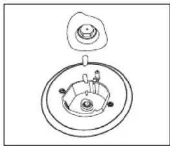
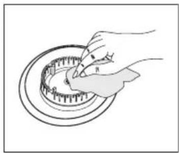
- Clean channels and lids of cooktop zones with soapy water and clean gas channels with a brush.
- In the course of cleaning your cooktop, never use flammable materials such as acid, thinner and gas.
- Do not wash plastic and aluminium parts of your cooktop in dishwasher.
- Clean vinegar, lemon, salt, coke and similar acid and alkaline containing substances poured on your cooktop immediately.
- In time, cooktop buttons turns hard or never turn any more, in such circumstances, it may be necessary that buttons are changed. The change should only be done by authorized service.
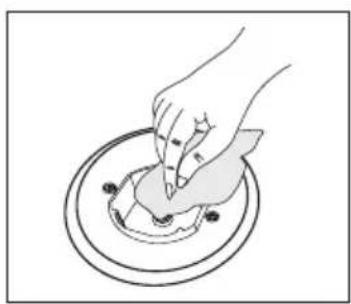
natural_image
Illustration of a hand pressing down on a circular object with small dots, no text or symbols presentFigure 13
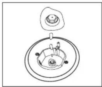
natural_image
Technical line drawing of a mechanical component with concentric rings and a small inset view (no text or symbols)Figure 15
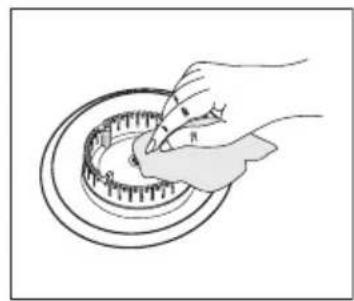
natural_image
Illustration of a hand using a tool to clean or inspect a circular mechanical component (no text or symbols visible)ROUBLES AND SOLUTION PROPOSALS
You can solve the troubles you can encounter at your product by checking the following points before calling technical service.
If cooktop does not operate;
- Check if power cable of cooktop is plugged in
- Examine with safe ways if electric exists on network
- Audit fuses.
• Control whether damage is available on power cable. - Check if main gas valve in your network is open
- Go through existence of breaking or twisting on gas pipe
- Be sure that gasp pipe is connected to cooktop in appropriate way.
• See over if suitable gas valve is used for your cooktop (Get periodical maintenance done)
If starter does not operate;
- Be sure that electric power cable of product is plugged in
- Clean the edge and body sections of ignition spark plugs found on burners with a wet and dirt remover materials thoroughly. Be sure that the channels present on burners are open and clean.
Gas type (LPG or natural gas) that your appliance is manufactured for is stated in the label found behind the product and that show technical features. If gas setting of your appliance is not the same as gas setting of your network, it should be adjusted by making change by an expert person. In the following table, injector, gas flow and power values of appliance is given according to gas type.
| INJECTOR, GAS FLOW And POWER TABLE | |||||||
| BURNERSPECIFICATIONS | G20,20 mbarG25,25 mbar | G20,25 mbar G20,13 mbar | |||||
| Gas Natural Gas Natural | Gas Natural | ||||||
| WokBurner (3,5) | Injector 1,40 mm 1,28 mm 1,60 mm | ||||||
| Gas Flow 0,333 m^3/h 0,333 m^3/h | |||||||
| Power 3,50 kW 3,50 kW 3,50 kW | |||||||
| WokBurner (2,5) | Injector 1,15 mm 1,06 mm 1,35 mm | ||||||
| Gas Flow 0,243 m^3/h 0,243 m^3/h | |||||||
| Power 2,50 kW 2,50 kW 2,50 kW | |||||||
| RapidBurner | Injector 1,15 mm 1,10 mm 1,45 mm | ||||||
| Gas Flow 0,276 m^3/h 0,276 m^3/h 0,276 m^3/h | |||||||
| Power 2,90 kW 2,90 kW 2,90 kW | |||||||
| Semi-RapidBurner | Injector 0,97 mm 0,92 mm 1,10 mm | ||||||
| Gas Flow 0,162 m^3/h 0,162 m^3/h | |||||||
| Power 1,70 kW 1,70 kW 1,70 kW | |||||||
| AuxiliaryBurner | Injector 0,72 mm 0,70 mm 0,85 mm | ||||||
| Gas Flow 0,96 m^3/h 0,96 m^3/h | |||||||
| Power 0,95 kW 0,95 kW 0,95 kW | |||||||
| INJECTOR, GAS FLOW And POWER TABLE | |||||||
| BURNERSPECIFICATIONS | G30,28-30 mbarG31,37 mbar | G30,50 mbar G30,37 mbar | |||||
| LPG LPG LPG | |||||||
| WokBurner (3,5) | Injector 0,96 mm 0,76 mm 0,96 mm | ||||||
| Gas Flow 254 g/h | 254 g/h | 254 g/h | |||||
| Power 3,50 kW 3,50 kW 3,50 kW | |||||||
| WokBurner (2,5) | Injector 0,82 mm 0,73 mm 0,78 mm | ||||||
| Gas Flow 182 g/h | 182 g/h | 182 g/h | |||||
| Power 2,50 kW 2,50 kW 2,50 kW | |||||||
| RapidBurner | Injector 0,85 mm 0,75 mm 0,85 mm | ||||||
| Gas Flow 211 g/h | 211 g/h | 211 g/h | |||||
| Power 2,90 kW 2,90 kW 2,90 kW | |||||||
| Semi-RapidBurner | Injector 0,65 mm 0,60 mm 0,65 mm | ||||||
| Gas Flow 124 g/h | 124 g/h | 124 g/h | |||||
| Power 1,70 kW 1,70 kW 1,70 kW | |||||||
| AuxiliaryBurner | Injector 0,50 mm 0,43 mm 0,50 mm | ||||||
| Gas Flow 69 | g/h | 69 | g/h | 69 | g/h | ||
| Power 0,95 kW 0,95 kW 0,95 kW | |||||||
ENVIRONMENTALLY-FRIENDLY DISPOSAL
natural_image
Symbol of a trash bin crossed with no text or numbers, representing environmental restriction (no text present)- Dispose of packaging in an environmentally friendly manner.
- This appliance is labelled in accordance with European Directive 2012/19/EU concerning used electrical and electronic appliances (waste electrical and electronic equipment - WEEE). The guideline determines the framework for the return and recycling of used appliances as applicable throughout to the EU.
PACKAGE INFORMATION
Packaging materials of the product are manufactured from recyclable materials in accordance with our National Environment Regulations. Do not dispose of the packaging materials together with the domestic or other wastes. Take them to the packaging material collection points designated by the local authorities.
DISPOSAL OF USED ELECTRICAL AND ELECTRONIC EQUIPMENT
natural_image
Symbol of a trash bin crossed with no text or numbers, representing environmental protection (no text present)This symbol on products or original documents means that used electric or electronic products must not be added to ordinary municipal waste. For proper disposal, renewal and recycling hand over these appliances to determined collection points. Alternatively, in some European Union states or other European countries you may return your appliances to the local retailer when buying an equivalent new appliance. Correct disposal of this product helps save valuable natural resources and prevents potential negative effects on the environment and human health, which could result from improper waste disposal. Ask your local authorities or collection facility for more details. In accordance with national regulations penalties may be imposed for the incorrect disposal of this type of waste.
For business entities in European Union states
If you want to dispose of electric or electronic appliances, ask your retailer or supplier for the necessary information.
Disposal in other countries outside the European Union.
This symbol is valid in the European Union. If you wish to dispose of this product, request the necessary information about the correct disposal method from the local council or from your retailer.
- Vážený uživateli,
- NÁKRES ELEKTRICKÉHO ZAPOJENÍ
- PLYN - BEZPEČNOSTNÍ ZAŘÍZENÍ (FFD)
- PROBLÉMY A NÁVRHY ŘEŠENÍ
- SCHÉMA ELEKTRICKÉHO PRIPOJENIA
- PLYN - BEZPEČNOSTNÉ ZARIADENIE (FFD)
- POUŽITIE VARNÉHO PANELA
- PROBLÉMY A MOŽNOSTÍ RIEŠENIA
- GAZ - URZĄDZENIE ZABEZPIECZAJĄCE (FFD)
- KONSERWACJA I CZYSZCZENIE
- PROBLEMY I ICH ROZWIĄZYWANIE
- GÁZ - BIZTONSÁGI BERENDEZÉS (FFD)
- ÁPOLÁS ÉS TISZTÍTÁS
- SHEMA ELEKTRIČNE PRIKLJUČITVE
- PLIN - VARNOSTNA NAPRAVA (FFD)
- UPORABA KUHALNE PLOŠČE
- VZDRŽEVANJE IN ČIŠČENJE
- MOREBITNE TEŽAVE IN REŠITVE
- INFORMACIJE O EMBALAŽI
- ENTWURF DES STROMANSCHLUSSES
- CONTENTS
- INTRODUCTION OF THE APPLIANCE
- CONTROL PANEL
- ELECTRICAL CONNECTION SCHEME
- Electrical Connection and Safety
- Gas Connection and Safety
- IF BUILT-IN OVEN IS PLACED UNDER COOKTOP
- INSTALLATION OF COOKSTOP
- COUNTER CUTTING SIZES AND INSTALLATION OF YOUR COOKTOP
- CORRECT PLACE FOR INSTALLATION
- VENTILATION OF ROOM
- TRANSFORMATION FROM NATURAL GAS TO LPG AND FROM LPG TO NATURAL GAS
- GAS BREAKING SAFETY APPLIANCE (FFD)
- USAGE OF YOUR COOKTOP
- Usage of Gas Cooktop
- WOK BURNER
- USAGE OF HOTPLATE
- MAINTENANCE AND CLEANING
- ROUBLES AND SOLUTION PROPOSALS
- You can solve the troubles you can encounter at your product by checking the following points before calling technical service.
- If cooktop does not operate;
- If starter does not operate;
- ENVIRONMENTALLY-FRIENDLY DISPOSAL
- PACKAGE INFORMATION
- DISPOSAL OF USED ELECTRICAL AND ELECTRONIC EQUIPMENT
- For business entities in European Union states
- Disposal in other countries outside the European Union.
Brand : Guzzanti
Model : GZ-8201
Category : Cooker