7HPC 640T (AN) R/HA - Cooker Hotpoint Ariston - Free user manual and instructions
Find the device manual for free 7HPC 640T (AN) R/HA Hotpoint Ariston in PDF.


| Product Type | Freestanding Cooker |
| Brand | Hotpoint Ariston |
| Model | 7HPC 640T (AN) R/HA |
| Overall Width | 60 cm (23.6 in) |
| Overall Depth | 60 cm (23.6 in) |
| Overall Height | 85-90 cm (33.5-35.4 in) adjustable |
| Weight | Approximately 55 kg (121 lb) |
| Power Supply | 230 V ~ 50 Hz, 16 A (electric oven/gas hob) |
| Energy Source | Gas hob with electric oven |
| Number of Cooking Zones | 4 gas burners |
| Oven Type | Electric multifunction oven |
| Oven Capacity | 71 L (usable) |
| Grill Function | Yes, electric grill |
| Self-Cleaning | Catalytic liners (rear wall) |
| Safety Features | Flame failure device on hob, child lock, cooling fan |
| Hob Material | Stainless steel |
| Oven Door Type | Removable, double-glazed |
| Storage Drawer | Yes, underneath oven |
| Spare Parts Availability | Available from Hotpoint Ariston service network |
Frequently Asked Questions - 7HPC 640T (AN) R/HA Hotpoint Ariston
User questions about 7HPC 640T (AN) R/HA Hotpoint Ariston
0 question about this device. Answer the ones you know or ask your own.
Ask a new question about this device
Download the instructions for your Cooker in PDF format for free! Find your manual 7HPC 640T (AN) R/HA - Hotpoint Ariston and take your electronic device back in hand. On this page are published all the documents necessary for the use of your device. 7HPC 640T (AN) R/HA by Hotpoint Ariston.
USER MANUAL 7HPC 640T (AN) R/HA Hotpoint Ariston
Operating Instructions
HOB
Contents
Operating Instructions,1
Warnings,2
Assistance,4
Description of the appliance,5
Installation,7
Start-up and use,11
Precautions and tips, 11
Maintenance and care,12
Troubleshooting,12
RU
Русский
WARNING: The appliance and its accessible parts become hot during use. Care should be taken to avoid touching heating elements. Children less than 8 years of age shall be kept away unless continuously supervised. This appliance can be used by children aged from 8 years and above and persons with reduced physical, sensory or mental capabilities or lack of experience and knowledge if they have been given supervision or instruction concerning use of the appliance in a safe way and understand the hazards involved. Children shall not play with the appliance. Cleaning and user maintenance shall not be made by children without supervision.
WARNING: Unattended cooking on a hob with fat or oil can be dangerous and may result in fire. NEVER try to extinguish a fire with water, but switch off the appliance and then cover flame e.g. with a lid or a fire blanket.
WARNING: Danger of fire: do not store items on the cooking surfaces.
Never use steam cleaners or pressure cleaners on the appliance.
Remove any liquid from the lid before opening it. Do not close the glass cover (if present) when the gas burners or electric hotplates are still hot.
The appliance is not intended to be operated by means of an external timer or separate remote control system.
CAUTION: the use of inappropriate hob guards can cause accidents.
RU
Предупреждения
• the type of problem encountered.
- appliance model (Mod.)
- serial number (S/N)
This information is found on the data plate located on the appliance and/or on the packaging.
RU
Description of the appliance
Overall view
- Support Grid for COOKWARE
- GAS BURNERS
- ELECTRIC HOTPLATE*
- Indicator light for ELECTRIC HOTPLATE*
- Control Knobs for ELECTRIC HOTPLATE*
- Control Knobs for GAS BURNERS
- Ignition for GAS BURNERS
-
SAFETY DEVICES
-
ELECTRIC HOTPLATES* may have different diameters and operate at different power levels.
- The INDICATOR LIGHT FOR ELECTRIC HOTPLATE* switches on whenever the selector knob is moved from the 'off' position.
- GAS BURNERS differ in size and power. Use the diameter of the cookware to choose the most appropriate burner to cook with.
- Control Knobs for GAS BURNERS and ELECTRIC HOTPLATE* adjust the power or the size of the flame.
• GAS BURNER IGNITION enables a specific burner to be lit automatically. - SAFETY DEVICE stops the gas flow if the flame is accidentally extinguished.
* Only available on certain models.
RU
Описание изделия
Общии вид
KZ
Курылғы сипаттамасы
Жалпы шолу
ARISTON
Installation
! Before operating your new appliance please read this instruction booklet carefully. It contains important information for safe use, installation and care of the appliance.
! Please keep these operating instructions for future reference. Pass them on to possible new owners of the appliance.
Positioning
! Keep packaging material out of the reach of children. It can become a choking or suffocation hazard (see Precautions and tips).
! The appliance must be installed by a qualified professional according to the instructions provided. Incorrect installation may cause harm to people and animals or may damage property.
! This unit may be installed and used only in permanently ventilated rooms in accordance with current national regulations. The following requirements must be observed:
- The room must be equipped with an air extraction system that expels any combustion fumes. This may consist of a hood or an electric fan that automatically starts each time the appliance is switched on.
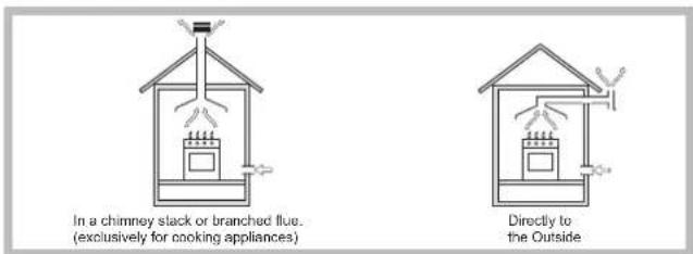
- The room must also allow proper air circulation, as air is needed for combustion to occur normally. The flow of air must not be less than 2^9 / h per kW of installed power.
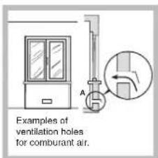
The air circulation system may take air directly from the outside by means of a pipe with an inner cross section of at least 100 cm ^2 ; the opening must not be vulnerable to any type of blockages.

The system can also provide the air needed for combustion indirectly, i.e. from adjacent rooms fitted with air circulation tubes as described above. However, these rooms must not be communal rooms, bedrooms or rooms that may present a fire hazard.
- Liquid petroleum gas sinks to the floor as it is heavier than air. Therefore, rooms containing LPG cylinders must also be equipped with vents to allow gas to escape in the event of a leak. As a result LPG cylinders, whether partially or completely full, must not be installed or stored in rooms or storage areas that are below ground level (cellars, etc.). It is advisable to keep only the cylinder being used in the room, positioned so that it is not subject to heat produced by external sources (ovens, fireplaces, stoves, etc.) which could raise the temperature of the cylinder above 50°C.
Fitting the appliance
The following precautions must be taken when installing the hob:
- Kitchen cabinets adjacent to the appliance and taller than the top of the hob must be at least 200 mm from the edge of the hob.
- Hoods must be installed according to their relative installation instruction manuals and at a minimum distance of 650 mm from the hob (see figure).
- Place the wall cabinets adjacent to the hood at a minimum height of 420 mm from the hob (see figure).
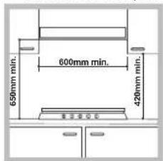
If the hob is installed beneath a wall cabinet, the latter must be situated at a minimum of 700 mm above the hob.
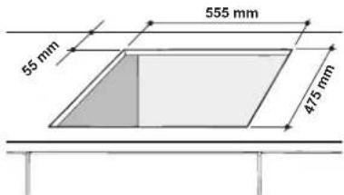
- The installation cavity should have the dimensions indicated in the figure. Fastening hooks are provided, allowing you to fasten the hob to tops that are between 20 and 40mm thick. To ensure the hob is securely fastened to the top, we recommend you use all the hooks provided.
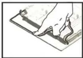
Before the installation remove the grids and burners from the hob and turn it upside down, making sure you don't damage the thermocouples and spark plugs.
natural_image
Illustration of a hand pressing down on a flat surface with a ruler, no text or symbols presentApply the seals that come with the appliance along the outer edges of the hob to prevent any passage of air, humidity and water (see Figure).
For proper application make sure the surfaces to be sealed are clean, dry and free of any grease/oil.
Hook fastening diagram
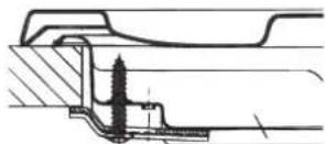
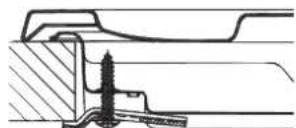
Hooking position for top H=20mm
Hooking position for top H=30mm
Front
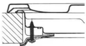
natural_image
Cross-sectional diagram of a mechanical assembly with no visible text or symbols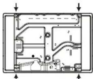
Hooking position for top H=40mm Back
! Use the hooks contained in the "accessory pack".
GB
- Where the hob is not installed over a built-in oven, a wooden panel must be installed as insulation. This must be placed at a minimum distance of 20 mm from the lower part of the hob.
Ventilation
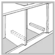
To ensure adequate ventilation, the back panel of the cabinet must be removed. It is advisable to install the oven so that it rests on two strips of wood, or on a completely flat surface with an opening of at least 45 x 560 mm (see diagrams).
natural_image
Pure technical line drawing of a cabinet or enclosure structure without any text, numbers, or symbols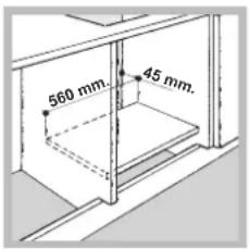
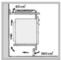
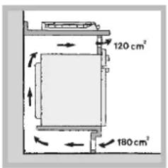
Where a hob is installed above an oven without a forced ventilation cooling system, adequate ventilation must be provided inside the cabinet by means of air holes through which air can pass (see figure).
Electrical connection
Hobs equipped with a three-pole power supply cable are designed to operate with alternating current at the voltage and frequency indicated on the data plate (this is located on the lower part of the appliance). The earth wire in the cable has a green and yellow cover. If the appliance is to be installed above a built-in electric oven, the electrical connection of the hob and the oven must be carried out separately, both for electrical safety purposes and to make extracting the oven easier.
Connecting the supply cable to the mains
Install a standardised plug corresponding to the load indicated on the data plate.
The appliance must be directly connected to the mains using an omnipolar circuit-breaker with a minimum contact opening of 3 mm installed between the appliance and the mains.
The circuit-breaker must be suitable for the charge indicated and must comply with current electrical regulations (the earthing wire must not be interrupted by the circuit-breaker). The supply cable must not come into contact with surfaces with temperatures higher than 50^ C.
! The installer must ensure that the correct electrical connection has been made and that it is compliant with safety regulations.
Before connecting to the power supply, make sure that:
- the appliance is earthed and the plug is compliant with the law.
- the socket can withstand the maximum power of the appliance, which is indicated on the data plate.
- the voltage is in the range between the values indicated on the data plate.
- the socket is compatible with the plug of the appliance. If the socket is incompatible with the plug, ask an authorised technician to replace it. Do not use extension cords or multiple sockets.
! Once the appliance has been installed, the power supply cable and the electrical socket must be easily accessible.
! The cable must not be bent or compressed.
! The cable must be checked regularly and replaced by authorised technicians only (see Assistance).
! The manufacturer declines any liability should these safety measures not be observed.
Gas connection
The appliance should be connected to the main gas supply or to a gas cylinder in compliance with current national regulations. Before carrying out the connection, make sure the cooker is compatible with the gas supply you wish to use. If this is not the case, follow the instructions indicated in the paragraph "Adapting to different types of gas".
When using liquid gas from a cylinder, install a pressure regulator which complies with current national regulations.
! Check that the pressure of the gas supply is consistent with the values indicated in Table 1 ("Burner and nozzle specifications"). This will ensure the safe operation and longevity of your appliance while maintaining efficient energy consumption.
Connection with a rigid pipe (copper or steel)
! Connection to the gas system must be carried out in such a way as not to place any strain of any kind on the appliance.
There is an adjustable L-shaped pipe fitting on the appliance supply ramp and this is fitted with a seal in order to prevent leaks. The seal must always be replaced after rotating the pipe fitting (seal provided with appliance). The gas supply pipe fitting is a threaded 1/2 gas cylindrical male attachment.
Connecting a flexible jointless stainless steel pipe to a threaded attachment
The gas supply pipe fitting is a threaded 1/2 gas cylindrical male attachment. These pipes must be installed so that they are never longer than 2000 mm when fully extended. Once connection has been carried out, make sure that the flexible metal pipe does not touch any moving parts and is not compressed.
! Only use pipes and seals that comply with current national regulations.
Checking the tightness of the connection
! When the installation process is complete, check the pipe fittings for leaks using a soapy solution. Never use a flame.
Adapting to different types of gas
To adapt the hob to a different type of gas other than default type (indicated on the rating plate at the base of the hob or on the packaging), the burner nozzles should be replaced as follows:
- Remove the hob grids and slide the burners off their seats.
- Unscrew the nozzles using a 7 mm socket spanner, and replace them with nozzles for the new type of gas (see table 1 "Burner and nozzle characteristics").
- Reassemble the parts following the above procedure in the reverse order.
- Once this procedure is finished, replace the old rating sticker with one indicating the new type of gas used. Sticker are available from any of our Service Centres.
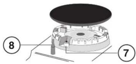
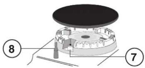
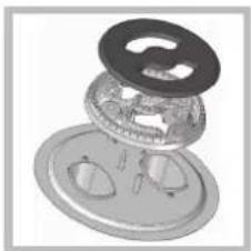
Replacing the Triple ring burner nozzles
-
Remove the pan supports and lift the burners out of their housing. The burner consists of two separate parts (see pictures).
-
Unscrew the nozzles using a 7 mm socket spanner. Replace the nozzles with models that are configured for use with the new type of gas (see Table 1). The two nozzles have the same hole diameter.
- Replace all the components by completing the above operations in reverse order.
natural_image
Exploded view of a mechanical component showing internal parts and mounting holes (no text or symbols)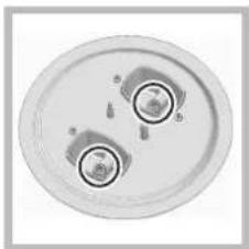
natural_image
Top-down view of a circular mechanical component with two circular features and mounting holes (no text or symbols visible)- Adjusting the burners' primary air Does not require adjusting.
- Setting the burners to minimum
- Turn the tap to the low flame position.
natural_image
Two mechanical mounting base configurations with no visible text or symbols-
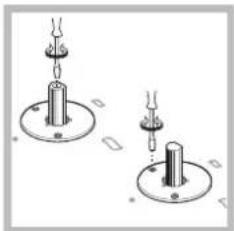
Remove the knob and adjust the adjustment screw, which is positioned in or next to the tap pin, until the flame is small but steady.
-
Having adjusted the flame to the required low setting, while the burner is alight, quickly change the position of the knob from minimum to maximum and vice versa several times, checking that the flame does not go out.
- Some appliances have a safety device (thermocouple) fitted. If the device fails to work when the burners are set to the low flame setting, increase this low flame setting using the adjusting screw.
- Once the adjustment has been made, replace the seals on the by-passes using sealing wax or a similar substance.
! If the appliance is connected to liquid gas, the regulation screw must be fastened as tightly as possible.
! Once this procedure is finished, replace the old rating sticker with one indicating the new type of gas used. Stickers are available from any of our Service Centres.
! Should the gas pressure used be different (or vary slightly) from the recommended pressure, a suitable pressure regulator must be fitted to the inlet pipe (in order to comply with current national regulations).
| DATA PLATE | |
| Electrical connections | see data plate |
 | This appliance conforms to the following European Economic Community directives:- 2006/95/EC dated 12/12/06 (Low Voltage) and subsequent amendments- 2004/108/EC dated 15/12/04 (Electromagnetic Compatibility) and subsequent amendments- 93/68/EEC dated 22/07/93 and subsequent amendments.- 2009/142/EC dated 30/11/06 (Gas) and subsequent amendments- 2012/19/EU and subsequent amendments. |
GB
Burner and nozzle specifications
| Table 1 | Liquid Gas | Natural Gas | ||||||||
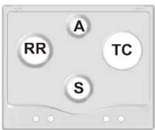
| Burner | Diameter (mm) | Thermal Power kW (p.c.s.*) | Thermal Power kW (p.c.s.*) Nominal Reduced | By-pass 1/100 (mm) | Nozzle 1/100 (mm) | Flow* g/h *** | ** | Thermal Power kW (p.c.s.*) Nominal | Nozzle 1/100 (mm) | Flow* l/h |
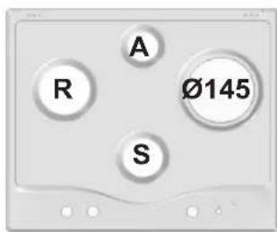
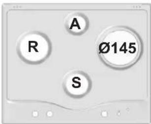
| Rapid (R) | 100 | 0.70 | 3.00 | 39 | 86 | 218 | 214 | 3.00 | 132 (H) | 286 |
| Reduced Rapid (RR) | 100 | 0.70 | 2.60 | 39 | 80 | 189 | 186 | 2.60 | 122 (H) | 248 |
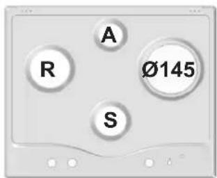
| Semi Rapid (S) | 75 | 0.40 | 1.65 | 28 | 64 | 120 | 118 | 1.65 | 96 (Z) | 157 |
| Auxiliary (A) | 55 | 0.40 | 1.00 | 28 | 50 | 73 | 71 | 1.00 | 79 (6) | 95 |
| Triple Crown (TC) | 130 | 1.50 | 3.30 | 61 | 65x2 | 240 | 236 | 3.60 | 103x2 | 343 |
| Supply pressures | Nominal (mbar)Minimum (mbar)Maximum (mbar) | 28-302035 | 372545 | 201725 | ||||||
* At 15°C and 1013,25 mbar - dry gas
** Propane P.C.S. = 50.37 MJ/Kg
*** Butane P.C.S. = 49.47 MJ/Kg
Natural P.C.S. = 37.78 MJ/m³
7HPC 640 /HA
7HPC 640 X/HA
7HPC 640 GH/HA
7HPC 640N /HA
7HPC 640N GH/HA
7HPC 640N X /HA
GPN 64 NW RFH
GPN 64 NI RFH
7HPC 640 T GH /HA
7HPC 640 T R /HA
7HPC 640 T X /HA
GPN 64 TA CI RFH
GPN 64 TO CI RFH
7HPC 631 X/HA
Start-up and use
! The position of the corresponding gas burner or electric hotplate* is shown on every knob.
Gas burners
Each burner can be adjusted to one of the following settings using the corresponding control knob:
- Off
Maximum
△. Minimum
To light one of the burners, hold a lit match or lighter near the burner and, at the same time, press down and turn the corresponding knob anti-clockwise to the maximum setting.
Since the burner is fitted with a safety device, the knob should be pressed for approximately 2-3 seconds to allow the automatic device keeping the flame alight to heat up.
When using models with an gas burner ignition, to light the selected burner press down and turn the corresponding knob anticlockwise to maximum position, keeping it pressed until the burner has ignited.
! If a flame is accidentally extinguished, turn off the control knob and wait for at least 1 minute before trying to relight it.
To switch off the burner, turn the knob in a clockwise direction until it stops (when reaches the “●” position).
Practical advice on using the burners
To ensure the burners operate efficiently:
- Use appropriate cookware for each burner (see table) so that the flames do not extend beyond the bottom of the cookware.
• Always use cookware with a flat base and a cover. - When the contents of the pan reach boiling point, turn the knob to minimum.
| Burner | ∅ Cookware Diameter (cm) |
| Rapid (R) | 24 - 26 |
| Reduced Rapid (RR) | 24 - 26 |
| Semi Rapid (S) | 16 - 20 |
| Auxiliary (A) | 10 - 14 |
| Triple Crown (TC) | 24 - 26 |
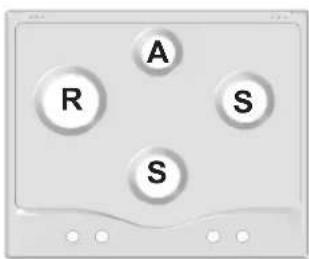
To identify the type of burner, refer to the designs in the section entitled, "Burner and Nozzle Specifications".
Electric hotplates\*
The corresponding knob may be turned clockwise or anti-clockwise and set to six different positions:
| Setting | Normal or Fast Plate |
| 0 | Off |
| 1 | Minimum power |
| 2-5 | Intermediate powers |
| 6 | Maximum power |
When the selector knob is in any position other than the off position, the 'on' light comes on.
Practical advice on using the electric hotplates\*
To avoid heat loss and damage to the hotplates, use pans with a flat base, whose diameter is no less than that of the hotplate itself.
| Setting | Normal or Fast Plate |
| 0 | Off |
| 1 | Cooking vegetables, fish |
| 2 | Cooking potatoes (using steam) soups, chickpeas, beans. |
| 3 | Continuing the cooking of large quantities of food, minestrone. |
| 4 | For roasting (average) |
| 5 | For roasting (above average) |
| 6 | For browning and reaching a boil in a short time |
! Before using the hotplates for the first time, you should heat them at maximum temperature for approximately 4 minutes, without placing any pans on them. During this initial stage, their protective coating hardens and reaches its maximum resistance.
Precautions and tips
! This appliance has been designed and manufactured in compliance with international safety standards. The following warnings are provided for safety reasons and must be read carefully.
General safety
• This is a class 3 built-in appliance.
- Gas appliances require regular air exchange to maintain efficient operation. When installing the hob, follow the instructions provided in the paragraph on “Positioning” the appliance.
• These instructions are only valid for the countries whose symbols appear in the manual and on the serial number plate.
- The appliance was designed for domestic use inside the home and is not intended for commercial or industrial use.
- The appliance must not be installed outdoors, even in covered areas. It is extremely dangerous to leave the appliance exposed to rain and storms.
- Do not touch the appliance with bare feet or with wet or damp hands and feet.
- The appliance must be used by adults only for the preparation of food, in accordance with the instructions outlined in this booklet. Any other use of the appliance (e.g. for heating the room) constitutes improper use and is dangerous. The manufacturer may not be held liable for any damage resulting from improper, incorrect and unreasonable use of the appliance.
- The openings used for ventilation and dispersion of heat must never be covered.
- Always make sure the knobs are in the “●”/“○” position when the appliance is not in use.
- When unplugging the appliance always pull the plug from the mains socket, do not pull on the cable.
- Never carry out any cleaning or maintenance work without having detached the plug from the mains.
- In case of malfunction, under no circumstances should you attempt to repair the appliance yourself. Repairs carried out by inexperienced persons may
* Only available on certain models.
GB
cause injury or further malfunctioning of the appliance. Contact a Service Centre (see Assistance).
• Always make sure that pan handles are turned towards the centre of the hob in order to avoid accidental burns.
- Do not close the glass cover (if present) when the gas burners or electric hotplates are still hot.
- Do not leave the electric hotplate switched on without a pan placed on it.
- Do not use unstable or deformed pans.
- The appliance should not be operated by people (including children) with reduced physical, sensory or mental capacities, by inexperienced individuals or by anyone who is not familiar with the product. These individuals should, at the very least, be supervised by someone who assumes responsibility for their safety or receive preliminary instructions relating to the operation of the appliance.
- Do not let children play with the appliance.
- The appliance is not intended to be operated by means of an external timer or separate remote-control system.
Disposal
- When disposing of packaging material: observe local legislation so that the packaging may be reused.
- The European Directive 2012/19/EU on Waste Electrical and Electronic Equipment (WEEE), requires that old household electrical appliances must not be disposed of in the normal unsorted municipal waste stream. Old appliances must be collected separately in order to optimise the recovery and recycling of the materials they contain and reduce the impact on human health and the environment. The crossed out "wheeled bin" symbol on the product reminds you of your obligation, that when you dispose of the appliance it must be separately collected.
Consumers should contact their local authority or retailer for information concerning the correct disposal of their old appliance.
Respecting and conserving the environment
- Make the most of your hot plate's residual heat by switching off cast iron hot plates 10 minutes before the end of your cooking time and glass ceramic hot plates 5 minutes before the end of cooking time.
- The base of your pot or pan should cover the hot plate. If it is smaller, precious energy will be wasted and pots that boil over leave encrusted remains that can be difficult to remove.
- Cook your food in closed pots or pans with well-fitting lids and use as little water as possible. Cooking with the lid off will greatly increase energy consumption.
- Use purely flat pots and pans.
- If you are cooking something that takes a long time, it's worth using a pressure cooker, which is twice as fast and saves a third of the energy.
Maintenance and care
Switching the appliance off
Disconnect your appliance from the electricity supply before carrying out any work on it.
Cleaning the appliance
! Do not use abrasive or corrosive detergents such as stain removers, anti-rust products, powder detergents or sponges with abrasive surfaces: these may scratch the surface beyond repair.
! Never use steam cleaners or pressure cleaners on the appliance.
- It is usually enough to wash the hob with a damp sponge and dry it with absorbent kitchen roll.
- The removable parts of the burners should be washed frequently with warm water and soap and any burnt-on substances removed.
- For hobs which ligth automatically, the terminal part of the electronic instant lighting devices should be cleaned frequently and the gas outlet holes should be checked for blockages.
- The electric hotplates should be cleaned with a damp cloth and lubricated with a little oil while still warm.
- Stainless steel can be marked by hard water that has been left on the surface for a long time, or by aggressive detergents containing phosphorus. After cleaning, rinse and dry any remaining drops of water.
Gas tap maintenance
Over time, the taps may become jammed or difficult to turn. If this happens, the tap must be replaced.
! This procedure must be performed by a qualified technician authorised by the manufacturer.
Troubleshooting
It may happen that the appliance does not function properly or at all. Before calling the service centre for assistance, check if anything can be done. First, check to see that there are no interruptions in the gas and electrical supplies, and, in particular, that the gas valves for the mains are open.
The burner does not light or the flame is not even around the burner.
Check whether:
• The gas holes on the burner are clogged.
- All the movable parts that make up the burner are mounted correctly.
• There are draughts near the appliance.
The flame dies in models with a safety device.
Check to make sure that:
- You pressed the knob all the way in.
- You keep the knob pressed in long enough to activate the safety device.
- The gas holes are not blocked in the area corresponding to the safety device.
The burner does not remain lit when set to minimum.
Check to make sure that:
• The gas holes are not blocked.
• There are no draughts near the appliance.
- The minimum setting has been adjusted properly.
The cookware is unstable.
Check to make sure that:
• The bottom of the cookware is perfectly flat.
- The cookware is positioned correctly at the centre of the burner.
- The pan support grids have been positioned correctly.
ARISTON
Установка
natural_image
Illustration of a hand using a pen to write on a document (no text or symbols visible)natural_image
Cross-sectional technical drawing of a mechanical assembly (no visible text or labels)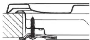
natural_image
Technical cross-section diagram of a mechanical assembly showing internal components and housing (no text or labels)natural_image
Pure technical line drawing of a cabinet or enclosure structure without any text, numbers, or symbols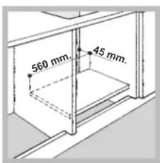
natural_image
Exploded view of a mechanical gear assembly (no text or symbols visible)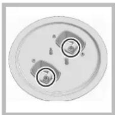
natural_image
Top-down view of a circular mechanical component with two central holes and mounting holes (no text or symbols visible)natural_image
Two identical mechanical mounting base diagrams with no text or symbols7HPC 640 T GH /HA
7HPC 640 T R /HA
7HPC 640 T X /HA
GPN 64 TA CI RFH
GPN 64 TO CI RFH
7HPC 631 X/HA
natural_image
Illustration of a hand using a tablet to press or write on a surface (no text or symbols visible)natural_image
Technical cross-sectional diagram of a mechanical assembly (no visible text or labels)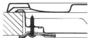
natural_image
Technical line drawing of a mechanical assembly with no visible text or symbolsnatural_image
Technical line drawing of a mechanical assembly with no visible text or symbols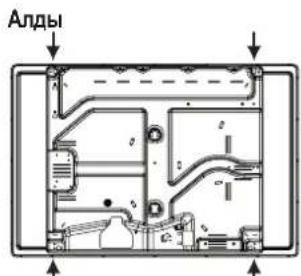
natural_image
Pure technical line drawing of a cabinet or enclosure structure without any text, numbers, or symbols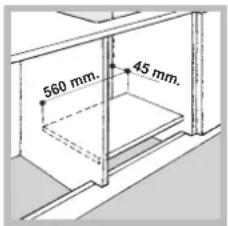
natural_image
Exploded view of a mechanical component with multiple circular features (no text or symbols visible)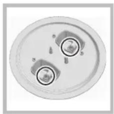
natural_image
Top-down view of a circular mechanical component with two cylindrical features and mounting holes (no text or symbols visible)natural_image
Two mechanical mounting base configurations with bolts and fasteners (no text or symbols)7HPC 640 T GH /HA
7HPC 640 T R /HA
7HPC 640 TX /HA
GPN 64 TA CI RFH
GPN 64 TO CI RFH
7HPC 631 X/HA
KZ
Косу және пайдалану
- Operating Instructions
- RU
- Предупреждения
- Description of the appliance
- Overall view
- Описание изделия
- Общии вид
- KZ
- Курылғы сипаттамасы
- Жалпы шолу
- ARISTON
- Installation
- Positioning
- Fitting the appliance
- Hook fastening diagram
- GB
- Ventilation
- Electrical connection
- Connecting the supply cable to the mains
- Gas connection
- Connection with a rigid pipe (copper or steel)
- Connecting a flexible jointless stainless steel pipe to a threaded attachment
- Checking the tightness of the connection
- Adapting to different types of gas
- Replacing the Triple ring burner nozzles
- Start-up and use
- Gas burners
- Practical advice on using the burners
- Electric hotplates\*
- Practical advice on using the electric hotplates\*
- Precautions and tips
- General safety
- Disposal
- Respecting and conserving the environment
- Maintenance and care
- Switching the appliance off
- Cleaning the appliance
- Gas tap maintenance
- Troubleshooting
- The burner does not light or the flame is not even around the burner.
- Check whether:
- The flame dies in models with a safety device.
- Check to make sure that:
- The burner does not remain lit when set to minimum.
- The cookware is unstable.
- Установка
- Косу және пайдалану
Brand : Hotpoint Ariston
Model : 7HPC 640T (AN) R/HA
Category : Cooker