L90CHDB17 - Range hood Logik - Free user manual and instructions
Find the device manual for free L90CHDB17 Logik in PDF.


| Product Type | Range Hood |
| Brand | Logik |
| Model | L90CHDB17 |
| Width | 90 cm |
| Dimensions (H x W x D) | Approx. 70 x 90 x 50 cm |
| Weight | Approx. 15 kg |
| Power Supply | 220-240 V ~ 50 Hz |
| Power Consumption | Approx. 300 W |
| Max Airflow | 650 m³/h |
| Noise Level | Up to 65 dB |
| Grease Filter | Aluminum, washable |
| Lighting | 2 x 40 W incandescent (E14) |
| Controls | Push buttons |
| Number of Speeds | 3 |
| Extraction Type | Ducted or recirculating (charcoal filter required) |
| Installation Type | Under cabinet or wall-mounted |
| Maintenance | Clean grease filter monthly |
| Replacement Parts | Grease filter, charcoal filter, bulbs |
| Safety Feature | Thermal cut-off (estimated) |
Frequently Asked Questions - L90CHDB17 Logik
User questions about L90CHDB17 Logik
0 question about this device. Answer the ones you know or ask your own.
Ask a new question about this device
Download the instructions for your Range hood in PDF format for free! Find your manual L90CHDB17 - Logik and take your electronic device back in hand. On this page are published all the documents necessary for the use of your device. L90CHDB17 by Logik.
USER MANUAL L90CHDB17 Logik
60cm/90cm Black T-box Chimney Hood
L60CHDB17 / L90CHDB17
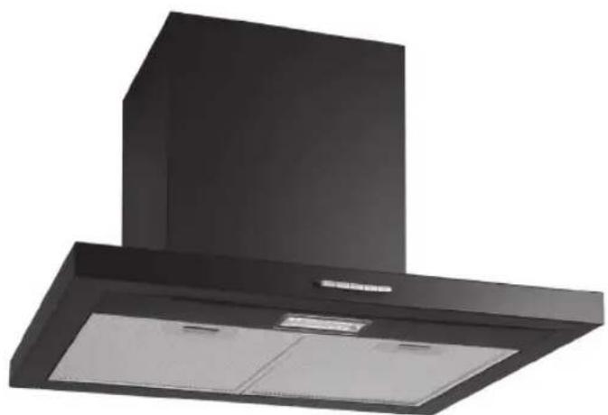
L60CHDB17
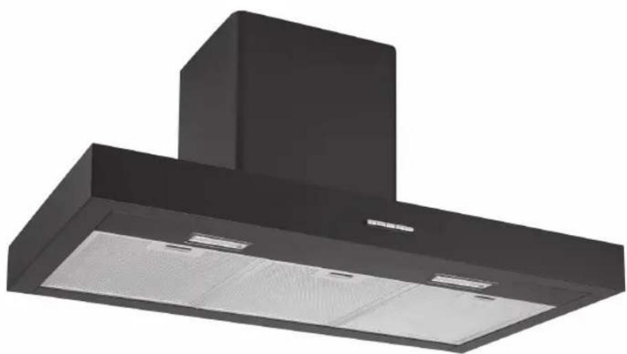
L90CHDB17

Contents
Safety Warnings....4
Unpacking 8
Product Overview....9
Control Panel....9
Modes of Operation 10
Air Extraction....10
Air Recirculation....10
Operation 10
To Select the Fan Motor Speed....10
Hob Lighting 10
Cleaning and Maintenance....11
Grease Filters....11
Cleaning the Grease Filters by Hand 12
Cleaning the Grease Filters in the Dishwasher 12
Carbon Filter Usage 13
Replacing Carbon Filters....13
Changing the Lamps....13
Hints and Tips 14
If Cooker Hood Does Not Operate ....14
Technical Specifications 15
Product Fiche 15
Installation....17
Product Overview....17
Safety Distance Between Hob and Cooker Hood 19
Connection for Air Extraction 20
Mounting the Cooker Hood ....21

Safety Warnings
- This appliance complies with all relevant local and national safety requirements. Inappropriate use can, however, lead to personal injury and damage to property.
- To avoid the risk of accidents and damage to the appliance, please read these instructions carefully before using it for the first time. They contain important information on the safety, installation, use and maintenance of the appliance.
- Keep these instructions in a safe place and ensure that all users are familiar with the contents. Pass them on to any future owner of the appliance.
Correct Application
• This appliance is not designed for commercial use. It is intended for use in domestic households. • It must only be used as a domestic appliance to extract vapours and remove odours from cooking.
- Any other usage is not supported by the manufacturer and could be dangerous. The manufacturer cannot be held liable for damage resulting from incorrect or improper use or operation of the appliance.
- This appliance can be used by children aged from 8 years and above and persons with reduced physical, sensory or mental capabilities or lack of experience and knowledge if they have been given supervision or instruction concerning use of the appliance in a safe way and understand the hazards involved. Children shall not play with the appliance. Cleaning and user maintenance shall not be made by children without supervision.
- Accessible parts may become hot when used with cooking appliances.
- If the supplied mains cable is damaged, it must be replaced by the manufacturer, its service agent or similarly qualified persons in order to avoid a hazard.
Safety with children
• This appliance is only intended for use by adults who have read these instructions. - This appliance is not a toy! To avoid the risk of injury, keep children well away and do not allow them to play with it or to use the controls. They will not understand the potential dangers posed by it. They should be supervised whenever you are working in the kitchen. - Older children may use the cooker hood only when its operation has been clearly explained to them and they are able to use it safely, recognising the dangers of misuse.
Correct Use
- Never use an open flame beneath the cooker hood. To avoid the danger of fire, do not flambé or grill over an open flame under the cooker hood. When switched on, the cooker hood could draw flames into the filter. Fat particles drawn into the cooker hood present a fire hazard.
- When using the cooker hood over a gas hob, ensure that any burners in use are always covered by a pan. Switch the cooking zone off when a pan is removed, even for a short time.
• Regulate the flame so that it does not burn up the sides of the pan. • Do not allow the pans to overheat excessively (e.g. when using a wok). • The cooker hood can become damaged when exposed to excessive heat. • Always switch the cooker hood on when a cooking zone is in use, otherwise condensation may collect in the hood, which could cause corrosion. - When cooking with oil or fat, chip pans and deep fat fryers etc, do not leave the pans unattended. Never leave an open grill unattended when grilling. Overheated oil and fat can ignite and could set the cooker hood on fire. - Do not use the cooker hood without the filters in place. This way you will avoid the risk of grease and dirt getting into the appliance and hindering its smooth operation. - The filters should be regularly cleaned or changed as appropriate. Saturated filters are a fire hazard. See "Cleaning and Maintenance". - The cooker hood can get very hot during cooking due to heat rising from the hob. Do not touch the housing or the grease filters until the cooker hood has cooled down. - Do not use a steam-cleaner to clean this appliance. Steam could reach the electrical components and cause a short circuit.
Technical safety
- Before installation, check the cooker hood for visible signs of damage. Under no circumstances should you use a damaged appliance. It could be dangerous.
- Before connecting the appliance to the mains supply, make sure that the voltage and frequency details given on the data plate correspond with the on-site electricity supply, otherwise the appliance could be damaged. Consult a qualified electrician if in any doubt.
- The electrical safety of this appliance can only be guaranteed when continuity is complete between the appliance and an effective earthing system complies with the current local and national safety regulations. It is most important that this basic safety requirement is present and tested regularly, and where there is any doubt, the household wiring system should be inspected by a qualified electrician. The manufacturer cannot be held liable for the consequences of an inadequate earthing system (e.g. electric shock). • For safety reasons, this appliance may only be used when it has been fully installed.
- Only open the housing as described in the instructions. Under no circumstances should any other parts of the housing be opened. Tampering with electrical connections or components and mechanical parts is highly dangerous to the user, and can cause operational faults.
- Installation, maintenance, and repairs may only be carried out by an authorized person in accordance with current national and local safety regulations. Repairs and other work by unqualified persons could be dangerous. The manufacturer cannot be held liable for unauthorized work. Faulty components must only be replaced with genuine original parts.
During installation, maintenance, and repair work, the appliance must be disconnected from the mains electricity supply. It is only completely isolated from the electricity supply when:
a) it is switched off at the isolator, or b) the mains fuse is disconnected, or c) it is switched off at the wall socket and the plug withdrawn, or d) the fuse of the fused spur connection unit is withdrawn.
- Do not connect the appliance to the mains electricity supply by a multi-socket unit or an extension lead. These do not guarantee the required safety of the appliance (e.g., danger of overheating). This appliance may only be used in mobile installations if a risk assessment of the installation has been carried out by a suitably qualified engineer.
- In areas which may be subject to infestation by cockroaches or other vermin, pay particular attention to keeping the appliance and its surroundings in a clean condition at all times.
Using at the same time as other heating appliances that depend on the air from the same room.

WARNING: Danger of toxic fumes.
Great care should be taken when using the cooker hood at the same time and in the
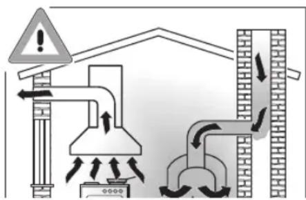
same room or area of the house as another heating appliance which depends on the air in the room. Such appliances include gas, oil, wood, or coal-fired boilers and heaters, continuous flow or other water heaters, gas hobs, cookers, or ovens which draw air in from the room and duct exhaust gases out through a chimney or extraction ducting.
- When used in extraction mode, the appliance draws air in from the room in which it is installed and from neighboring rooms.
- If there is insufficient air, an underpressure will occur. The heating appliance may be starved of oxygen, impairing combustion.
- Harmful gases could be drawn out of the chimney or extraction ducting back into the room, with potentially fatal consequences.
- In order to ensure safe operation, and to prevent gases given off by the heating appliances from being drawn back into the room when the cooker hood and the heater are in operation simultaneously, an underpressure of 0.04 mbar (4 Pa) is the maximum permissible in the room.
- Ventilation can be maintained by air inlets which must not be blocked, in windows, doors, and outside wall vents, or by other technical measures, such as ensuring that the cooker hood can only be switched on when the heating appliance is switched off or vice versa. A ventilation brick alone is not generally sufficient to ensure safe ventilation.
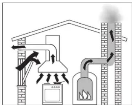

The overall ventilation condition of the dwelling must be taken into account. If in any doubt, the advice of a competent builder or, for gas, a qualified gas fitter (Gas Safe registered in the UK) must be sought.
- If the only way of ensuring adequate ventilation is via an open window, a window contact switch should be fitted to ensure that the cooker hood can only operate when the window is opened sufficiently. A window contact switch kit is available from good builders' merchants. Take care when ventilating the room through an open window that ventilation is not impaired by a closed blind or curtain. If the hood is being operated in recirculation mode, the above restrictions do not apply.

If in any doubt, the advice of a qualified builder, gas fitter (Gas Safe registered in the UK) or electrician must be sought.
Correct Installation
- Refer to the cooker or hob manufacturer's instructions as to whether a cooker hood may be operated above the cooker/hob.
- The minimum safe distances between the top of the cooker or hob and the bottom of the cooker hood given in the Installation section of this booklet must be maintained, unless the hob/cooker manufacturer states that a greater safe distance is required.
- If more than one appliance is fitted beneath the cooker hood, and they have different minimum safe distances to the cooker hood, select the greater distance. • Safety regulations prohibit the fitting of a cooker hood over solid fuel stoves.
- All ducting, pipework and fittings must be of non-flammable material. These can be obtained from builders' merchants.
- The appliance must not be connected to a chimney or vent flue which is in use. Neither should it be connected to ducting which ventilates rooms with fireplaces.
- If exhaust air is to be extracted into a chimney or ventilation duct no longer used for other purposes, seek professional advice.
Accessories
• Only use genuine original spare parts and accessories with this appliance.

The manufacturer cannot be held liable for damage caused by non-compliance with these Warning and Safety instructions.
Thank you on the purchase of your new Logik Cooker Hood.
We recommend that you spend some time to read this manual in order to fully understand how to install and operate it correctly.
Read all the safety warnings carefully before use and keep this manual for future reference.

Unpacking
Remove all items from the packaging. If you dispose of it, please do so according to local regulations. The following items are included:
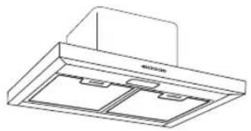
Main Unit (L60CHDB17)
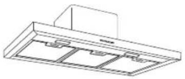
Main Unit (L90CHDB17)
Hanging Plate
(for mounting product on the wall)
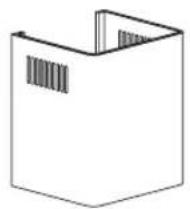

4 x 8mm Screws X 4Internal Chimney X 1
Internal Chimney Connection Plate (for fixing internal chimney on the wall)
External Chimney X 1 ∅8 x 40mm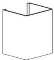
Adapter X 1 (for reducing outlet diameter from 150-120mm)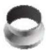
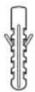
Plastic Wall Plug X 9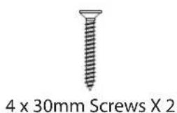
4 x 40mm Screws X 7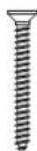
Drill Template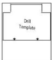
Instruction Manual

If items are missing or damaged, please contact Partmaster (UK only). Tel: 0344 800 3456 for assistance.
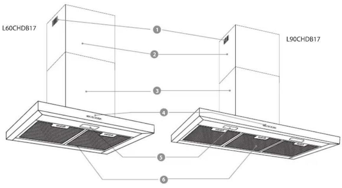
- Recirculation Vents
- Control Panel
- Internal Chimney
- Illumination
- External Chimney
- Aluminium Filter
Control Panel
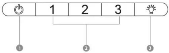
- OFF button
- Motor speed buttons
- Lamp button

Modes of Operation
The cooker hood works with
Air Extraction
The air is drawn in and cleaned by the grease filters and directed outside.
When the cooker hood is switched on, the non-return flap opens for the cooking vapours to be ducted away.
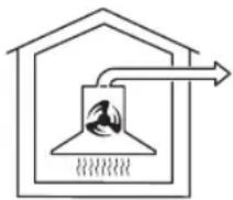

Ensure there is adequate ventilation in the room when the cooker hood is used at the same time as other appliances burning gas or other fuels.
Air Recirculation
The air is drawn in and cleaned first by the grease filters and then by a carbon filter. The cleaned air is then recirculated back into the kitchen through the recirculation vents in the top of the cooker hood chimney.
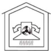

• Carbon filters are available as an optional extra, see rear page for ordering details. - Before using the cooker hood in recirculation mode, ensure that the carbon filters are in place. See "Cleaning and Maintenance"

Operation
To Select the Fan Motor Speed
- The unit has 3 motor speeds "1", "2" and "3".
- For short periods of cooking food with intensive vapours and a strong aroma, e.g. when searing meat, you may wish to select the highest setting "3".
- To turn the motor fan off, press the OFF button.

• Do not flambé under the cooker hood. - Accessible parts may become hot when used with cooking appliances.
Hob Lighting

The hob lighting can be switched on and off independently of the fan by pressing the LAMP button.

Cleaning and Maintenance

- Before any cleaning or maintenance work is carried out, disconnect the cooker hood from the mains power supply. Ensure that:
- it is switched off at the isolator, or
- it is switched off at the wall socket and the plug is withdrawn, or
- the fuse from the fused spur connection unit is withdrawn, or
- the mains fuse is disconnected.
- The surfaces and controls are susceptible to scratches and abrasions. Please observe the following cleaning instructions.
- All external surfaces and controls can be cleaned using a little washing-up liquid applied with a damp soft sponge or cloth.

Only use a damp cloth as water could get into the unit and cause damage.
• Wipe dry using a soft cloth.

Do not use:
• Cleaning agents containing soda, acids, chlorides or solvents. - Abrasive cleaning agents, e.g. powder cleaners or cream cleaners and abrasive sponges, as well as pot scourers or sponges which have been used previously with abrasive cleaning agents as these will damage the surface material.
Grease Filters
The re-usable metal grease filters in the appliance remove solid particles (grease, dust, etc.) from the kitchen vapours, preventing soiling of the cooker hood.
The grease filters should be cleaned regularly (at least every 3-4 weeks) to avoid a build-up of grease.

Dirty filters are a fire hazard.
- To take out the grease filter, press the plastic catch.
- Pull the aluminium filter downwards.

To avoid damaging the filters or the hob below, make sure you hold the filters securely at all times when handling them.
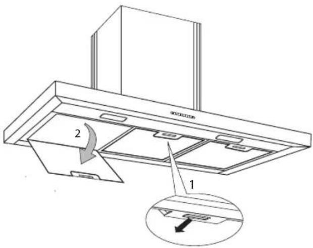
Cleaning the Grease Filters by Hand
- Clean the filters with a soft nylon brush in a mild solution of hot water and a little washing-up liquid.

Do not use:
• Cleaning agents containing descaling agents. • Powder cleaners, cream cleaners or abrasive all-purpose cleaners. - Oven cleaners.
Cleaning the Grease Filters in the Dishwasher
- Place the filters as upright as possible in the lower basket, with the short sides upright. Wash using a 65°C programme, ensuring the spray arm is not obstructed. • Use a mild dishwasher detergent.

Depending on the cleaning agent used, cleaning the filters in a dishwasher can cause permanent discolouration to the surface. However, this will not affect the functioning of the filters in any way.
• After cleaning, leave the filters to dry on an absorbent surface before replacing them. - When removing the filters for cleaning, also clean off any residues of oil or fat from the now accessible housing to prevent the risk of these catching fire.
When putting the grease filters back in position, ensure that the locking clips are facing down towards the hob.
Carbon Filter Usage
Your product is compatible with one type of carbon filter (carbon filters are not provided).
- Before installing or replacing the carbon filters, you should switch off and disconnect the electricity supply. • The carbon filters should never be washed.
- The grease filters should be installed on the product even when carbon filters are not being used. Do not use your product without the grease filters.
Replacing Carbon Filters
• It is necessary to install 2 carbon filters in your product. - Open all the grease filters, see page 7 for details. - To attach the carbon filters, place them on the connection channels on the motor and turn the left hand filter anticlockwise and the right hand filter clockwise. - In order to remove the carbon filters, turn the left hand filter clockwise and the right hand filter anticlockwise.

- Replace the carbon filters when they no longer absorb kitchen odours effectively. They should, however, be replaced at least every 3 months to prevent a risk of fire. • Used carbon filters can be disposed of with the normal household waste.
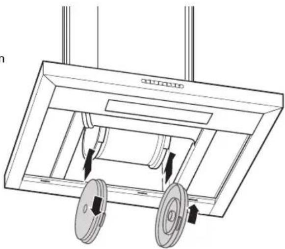
- Replace all the grease filters to the main unit.
Changing the Lamps
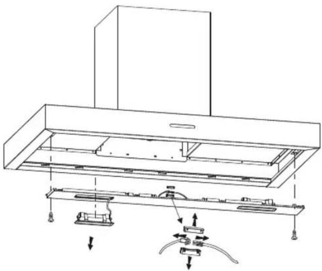
- Press the plastic catch and take out the grease filter.
- Unscrew the lamp cover.
- Pull out the LED light box and you will find a connection box.
- Disassemble the connection box and disconnect the LED light box.
- Replace with a new LED light box.
- Screw the lamp cover and replace the grease filter.
| Problem Solution | |
| Cooker hood does not operate | Check Electric connection.(The supply voltage should be 220-240 V. The cooker hood must be connected to an earthed socket)Check motor speed selector.(Motor speed selector should be in position I, II or III) |
| Lamp does not light | Check Electric connection.(The supply voltage should be 220-240 V. The cooker hood must be connected to an earthed socket)Check lamp switch.(Lamp switch should be in the on position)Check light bulbs. |
| Air suction of cooker hood is weak | Check aluminium filters.(Aluminium grease filters should be washed once a month under normal conditions)Check air outlet chimney.(Air outlet chimney should be open)Check carbon filters.(If the unit operates with carbon filters, they should be replaced quarterly) |
If Cooker Hood Does Not Operate
Before Contacting Service:
Be sure that the mains plug is connected to the mains socket and the fuse in the installation is in good condition. Check your cooker hood according to the above table. If the problem continues, contact your retailer or an authorised service agent.

Technical Specifications
| Model no. L60CHDB17 L90CHDB17 | |
| Extraction Rate (m3/h) 526.7 526.7 | |
| Voltage (V) 220 – 240 ~ 220 – 240 ~ | |
| Frequency (Hz) 50 50 | |
| Total Power (W) 102.5 105 | |
| Lamp 1 x 2.5 W 2 x 2.5 W |
Features and specifications are subject to change without prior notice.

Product Fiche
Model no.: L60CHDB17
| Symbol | Value | Unit | |
| Annual Energy Consumption | AEChood | 56.9 | kWh/a |
| Time increase factor | f | 1.7 | |
| Fluid Dynamic Efficiency | FDEhood | 8.7 | |
| Fluid Dynamic Efficiency class | E | ||
| Energy Efficiency Index | EEIhood | 86.9 | |
| Energy Efficiency class | D | ||
| Measured airflow rate at the best efficiency | QBEP | 306.6 | m3/h |
| Measured air pressure at best efficiency point | PBEP | 91 | Pa |
| Maximum airflow | Qmax | 526.7 | m3/h |
| Air flow at working point (highest setting) | 474.6 | m3/h | |
| Air flow at working point (lowest setting) | 381 | m3/h | |
| Measured electric power input at best efficiency point | WBEP | 88.7 | W |
| Nominal power of the lighting system | WL | 2.5 | W |
| Average illumination of the lighting system on the cooking surface | Emiddle | 99 | lux |
| Lighting Efficiency | LEhood | 39.4 | lux/w |
| Lighting efficiency class | A | ||
| Grease Filtering Efficiency (%) | GFEhood | 79.2 | |
| Grease Filtering Efficiency (GFE hood ) class | C | ||
| Measured power consumption on standby mode | PS | - | W |
| Measured power consumption on off mode | PO | 0 | W |
| Sound power level | LWA | 58 | dB |
The above table indicates the information for the cooker hood. The test result is done as per the relevant requirements of EU No 65/2014 and EU No 66/2014.
Model no.: L90CHDB17
| Symbol Value Unit | |||
| Annual Energy Consumption AEC | hood | 58.7 kWh/a | |
| Time increase factor f 1.7 | |||
| Fluid Dynamic Efficiency FDE | hood | 8.7 | |
| Fluid Dynamic Efficiency class E | |||
| Energy Efficiency Index EEI | hood | 87.9 | |
| Energy Efficiency class D | |||
| Measured airflow rate at the best efficiency Q | BEP | 306.6 m | 3 /h |
| Measured air pressure at best efficiency point P | BEP | 91 Pa | |
| Maximum airflow Q | max | 526.7 m | 3 /h |
| Air flow at working point (highest setting) | 474.6 m | 3 /h | |
| Air flow at working point (lowest setting) | 381 | m3/h | |
| Measured electric power input at best efficiency point | W_BEP | 88.7 | W |
| Nominal power of the lighting system | W_L | 5.0 | W |
| Average illumination of the lighting system on the cooking surface | E_middle | 143 | lux |
| Lighting Efficiency | LE_hood | 28.6 | lux/w |
| Lighting efficiency class | A | ||
| Grease Filtering Efficiency (%) | GFE_hood | 81.6 | |
| Grease Filtering Efficiency (GFE hood ) class | C | ||
| Measured power consumption on standby mode | P_S | - | W |
| Measured power consumption on off mode | P_O | 0 | W |
| Sound power level | L_WA | 58 | dB |
The above table indicates the information for the cooker hood. The test result is done as per the relevant requirements of EU No 65/2014 and EU No 66/2014.
Product Overview
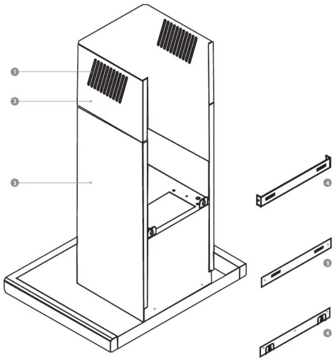
- Grill For Air Outlet
- Internal Chimney
- External Chimney
- Internal Chimney Connection Plate
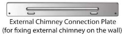
- External Chimney Connection Plate
- Hanging Plate
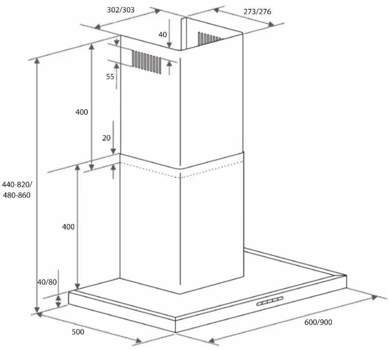
All dimensions shown are in mm.
Safety Distance Between Hob and Cooker Hood

When planning the installation height of your cooker hood, the minimum safe distance between the top of a cooker or hob and the bottom of the cooker hood should be at least 650mm, unless a greater distance is specified by the manufacturer of your cooking appliance.
- When deciding on the safe distance between the hob and cooker hood, please note that a distance greater than 650mm above electric cookers/hobs may be preferable to give more working space under the hood.
- Account should also be taken of the height of the person who will be using the hood most often. The person should have sufficient space to work comfortably at the hob, and also be able to reach the hood controls with ease.
- Please be aware that if positioned too high, extraction will be inefficient.
- If you want the top of the cooker hood telescopic extension piece to be mounted flush with the ceiling, make sure there is adequate space below the appliance for safe operation.
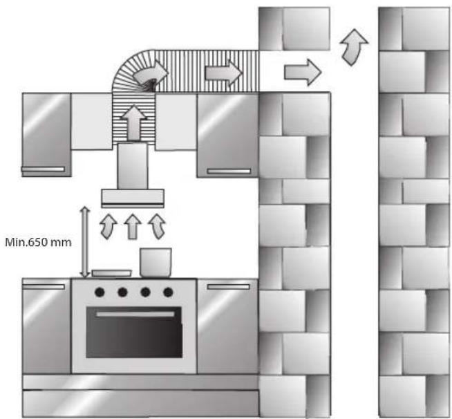
Connection for Air Extraction

To avoid the danger of toxic fumes, please observe the Safety Warnings.
This is especially crucial when using the cooker hood at the same time as another heating appliance which relies on air from the same room.
The cooker hood should be installed according to the local and national building regulations. Seek approval from the building inspector where necessary.
Only use smooth pipes or flexible hoses made from non-flammable materials for the extraction ducting.
To achieve the greatest possible air extraction with the lowest noise level, please note the following:
- To ensure efficient air extraction, the diameter of the exhaust ducting should not be less than 120mm.
- If flat ducting is being used, the cross-sectional area must not be smaller than the cross sectional area of the exhaust connection. • All ducting, pipework and fittings must be made of non-flammable materials. • The exhaust ducting should be as short and straight as possible. • Only use wide radius bends. • The exhaust ducting should not be kinked or compressed.
- Ensure that all connections are strong and airtight.
- Where ducting is horizontal, it must be laid to slope away at least 1 cm per metre. This is to ensure that condensation cannot drain back into the cooker hood.
- If the exhaust air is to be ducted into the open air, the installation of a telescopic wall vent or roof vent is recommended.
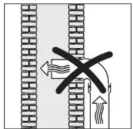
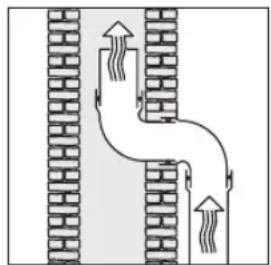

If the exhaust ducting is to run through rooms, ceiling space etc. where there may be great variations in temperature between the different areas, the problem of condensation will need to be addressed. The exhaust ducting will need to be suitably insulated.
Mounting the Cooker Hood

• We recommend professional tradespersons are consulted prior to the fitting of this appliance. • Each installation is different and these instructions should be used as a guide only. If in doubt consult professional tradespersons, - Air must not be discharged into a flue that is used for exhausting fumes from appliances burning gas or other fuels.
- We recommend that for air extraction installations, a professional tradesperson is consulted prior to any work being undertaken. A 150mm or 120mm hole will need to be provided for the aluminium flexible hose (not supplied) to duct the extracted air to the outside. For recirculation operation, a competent layman can follow the instructions below. If you are in any doubt, we recommend you consult a professional tradesperson.
- Ensure there is an available switched mains socket adjacent to the hood to power the appliance. If this is not available, do not use extension leads. We recommend you consult a qualified electrician prior to commencing any work.
- The unit itself is with 150mm air outlet. If your kitchen is with 120mm hole; you need to mount Adaptor (AD) onto air outlet before connecting the aluminium flexible hose.
- You can either use the drill template to mark the position of the fixing screws or position the hood on the wall and mark the position "A", "B", "C", "D" and "E" as shown.
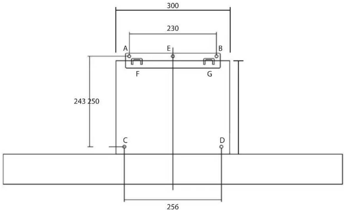
- Screw the External Chimney to the External Chimney Connection Plate by screwing 2 pcs of the 4 x 8mm screws through the mounting holes at the top of External Chimney. Screw the Internal Chimney to the Internal Chimney Connection Plate by screwing the other 2 pcs of 4 x 8mm screws through the mounting holes at the top of Internal Chimney.

Before drilling any holes, ensure there is no pipe work or wires buried in the wall.
6. Assembling Hanging Plate Holes
Drill (A, B, C, D, E) holes on marked points by using a Φ8mm drill bit. Push 5 pcs of plastic wall plugs into the drilled holes (A, B, C, D, E). Put the hanging plate on the holes A, B, E. Using the supplied 4 x 40mm screws; screw the hanging plate into the A, B, E holes.
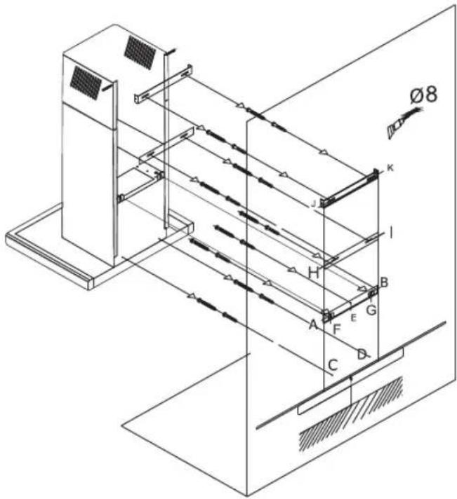
7. Mounting the Hood to Wall
Hang the hood on the two hooks (F, G) on the Hanging Plate. Using the supplied 4 x 30mm screws, screw the Hood into Φ8 mm wall plugs (C, D) fixed in the wall.
Ensure the hood is level and then fully tighten all the screws.
8. Mounting the Chimneys to Wall
Place the External Chimney over the Internal Chimney and over the hood motor enclosure. Adjust the height you want for the Internal Chimney. Mark the positions "H" "I" "J" "K" as shown. Drill (H, I, J, K) holes on marked points by using a Φ8mm drill bit. Push 4 pcs of plastic wall plugs into the drilled holes (H, I, J, K). Screw the External Chimney into Φ8mm wall plugs (H, I) fixed in the wall. Screw the Internal Chimney into Φ8mm wall plugs (J, K) fixed in the wall.
- Ensure all protective coverings have been removed from the metal surfaces prior to use.
- Follow the operation instructions in this manual for safe operation of this appliance.

For general information about this appliance
and handy hints and tips, please visit
www.knowhow.com/knowledgebank or call 0344 5611234.

Visit Partmaster.co.uk today for the easiest way to buy electrical spares and accessories. With over 1 million spares and accessories available we can deliver direct to your door the very next day. Visit
www.partmaster.co.uk or call 0344 800 3456 (UK customers only). Calls charged at National Rate.
The symbol on the product or its packaging indicates that this product must not be disposed of with your other household waste. Instead, it is your responsibility to dispose of your waste equipment by handing it over to a designated collection point for the recycling of waste electrical and electronic equipment. The separate collection and recycling of your waste equipment at the time of disposal will help conserve natural resources and ensure that it is recycled in a manner that protects human health and the environment.
For more information about where you can drop off your waste for recycling, please contact your local authority, or where you purchased your product.
DSG Retail Ltd. (co. no. 504877)
1 Portal Way, London, W3 6RS, UK
- CM/90CM BLACK T-BOX CHIMNEY HOOD
- CONTENTS
- SAFETY WARNINGS
- UNPACKING
- PRODUCT OVERVIEW
- MODES OF OPERATION
- OPERATION
- CLEANING AND MAINTENANCE
- HINTS AND TIPS
- TECHNICAL SPECIFICATIONS
- PRODUCT FICHE
- INSTALLATION
- CORRECT APPLICATION
- SAFETY WITH CHILDREN
- CORRECT USE
- TECHNICAL SAFETY
- USING AT THE SAME TIME AS OTHER HEATING APPLIANCES THAT DEPEND ON THE AIR FROM THE SAME ROOM
- WARNING: DANGER OF TOXIC FUMES
- CORRECT INSTALLATION
- ACCESSORIES
- THANK YOU ON THE PURCHASE OF YOUR NEW LOGIK COOKER HOOD
- CONTROL PANEL
- AIR EXTRACTION
- AIR RECIRCULATION
- TO SELECT THE FAN MOTOR SPEED
- HOB LIGHTING
- DO NOT USE
- GREASE FILTERS
- CLEANING THE GREASE FILTERS BY HAND
- CLEANING THE GREASE FILTERS IN THE DISHWASHER
- CARBON FILTER USAGE
- REPLACING CARBON FILTERS
- CHANGING THE LAMPS
- IF COOKER HOOD DOES NOT OPERATE
- BEFORE CONTACTING SERVICE
- SAFETY DISTANCE BETWEEN HOB AND COOKER HOOD
- CONNECTION FOR AIR EXTRACTION
- MOUNTING THE COOKER HOOD
- ASSEMBLING HANGING PLATE HOLES
- MOUNTING THE HOOD TO WALL
- MOUNTING THE CHIMNEYS TO WALL
Brand : Logik
Model : L90CHDB17
Category : Range hood