CH650B - Range hood Tricity Bendix - Free user manual and instructions
Find the device manual for free CH650B Tricity Bendix in PDF.


| Product Type | Range hood |
| Brand | Tricity Bendix |
| Model | CH650B |
| Width | 600 mm |
| Depth | 500 mm |
| Height (min-max) | 600-750 mm |
| Weight | 12 kg |
| Power Supply | 220-240 V ~ 50 Hz |
| Connection Power | 200 W |
| Motor Power | 150 W |
| Lighting Power | 2 x 40 W (max) |
| Extraction Rate (max) | 600 m³/h |
| Noise Level (max) | 65 dB(A) |
| Number of Speeds | 3 |
| Filter Type | Grease filter (aluminum or metal) |
| Filter Cleaning | Washable in dishwasher or by hand |
| Charcoal Filter (optional) | Yes, for recirculation mode |
| Installation Type | Built-in or under-cabinet |
| Exhaust Diameter | 150 mm |
| Controls | Sliding or push-button controls |
| Energy Class | B (typical) |
| Annual Energy Consumption | 70 kWh/a (typical) |
| Fluid Dynamic Efficiency Class | D (typical) |
| Grease Filter Efficiency Class | C (typical) |
| Lighting Efficiency Class | E (typical) |
| Noise Class | D (typical) |
Frequently Asked Questions - CH650B Tricity Bendix
User questions about CH650B Tricity Bendix
0 question about this device. Answer the ones you know or ask your own.
Ask a new question about this device
Download the instructions for your Range hood in PDF format for free! Find your manual CH650B - Tricity Bendix and take your electronic device back in hand. On this page are published all the documents necessary for the use of your device. CH650B by Tricity Bendix.
USER MANUAL CH650B Tricity Bendix
Better Products. Better Value.

natural_image
Illustration of various household appliances including refrigerator, washing machine, oven, and microwave (no text or symbols)Integrated Cooker Hood - CH 650
Operating and Installation Instructions

natural_image
Technical diagram of a mechanical device showing internal components and airflow direction (no text or labels)
natural_image
Technical line drawing of a mechanical device with internal components and directional arrows (no text or symbols)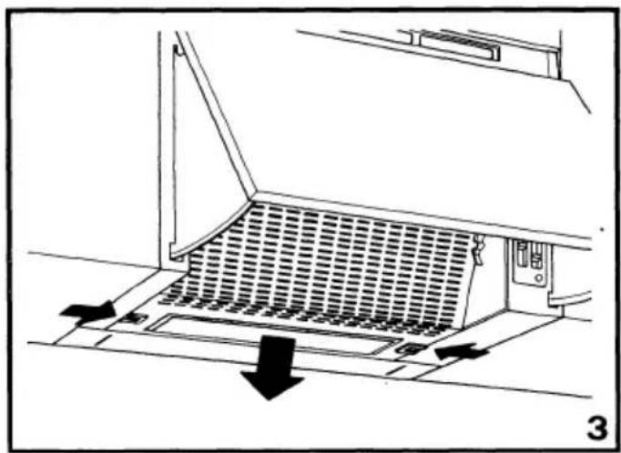
natural_image
Diagram of a kitchen ventilation system with airflow arrows and panel structure (no text or symbols)

natural_image
Line drawing of a mechanical device with directional arrows indicating motion or force (no text or symbols)
natural_image
Technical line drawing of a mechanical device with a wheel and rotating components (no text or symbols)Please refer to the sections in this booklet that apply to your particular model: Page
Drawings 1
Contents 2
Warnings....
General Information
Electrical Connection .... 4
Unpacking 5
Installation - Positioning ....5
Installation - Wall Fitting....5
Installation - Fitting the Decor Panel......€
Installation - Ducting Fitting
Operating Instructions....7
Recirculation
Maintenance and Cleaning ....
Do's and Don'ts....
Help Us To Help You ....
Customer Relations ....\$
Before Calling a Service Engineer ....
Tricity Bendix Service Centres 9, 10
TECHNICAL SPECIFICATIONS
| DIMENSIONS | Width | cm 59.8 | |
| Height | cm 35.0 | ||
| Depth | cm 27.0 ÷ 36.0 | ||
| Depth with visor open | cm 58.0 ÷ 67.0 | ||
| WEIGHT | Gross | kg 11.4 | |
| Net | kg 10.6 | ||
| ELECTRICAL CONNECTION | Voltage (~50Hz) | 230-240 V | |
| Fan | 115 W | ||
| Lamp 2 x 40 W | 80 W | ||
| Consumption | 195 W | ||
| PERFORMANCE | Speed | 1 | 2 |
| Capacity m^3/h | 150 | 220 | |
| Capacity lt/sec | 42 | 61 | |
| Pressure mm H_2O | 14 | 23 | |
| Noise level dbA | 47 | 52 | |
WARNINGS
It is most important that this instruction book should be retained with the appliance for future reference. Should the appliance be sold or transferred to another owner, or should you move house and leave the appliance always ensure that the book is supplied with the appliance in order that the new owner can be acquainted with the functioning of the appliance and the relevant warnings. Please ensure that you have read the whole instruction book before using the appliance and that you follow the recommendations given.
These warnings are provided in the interest of safety. They must be read carefully before installing or using the appliance.
This appliance is designed to be operated by adults. Children should not be allowed to tamper with the controls or play with the product.
It is dangerous to alter the specification: or attempt to modify the appliance in any way.
Any electrical work required must be undertaken by a qualified electrician or a competent person.
This product should be serviced by an authorised Tricity Bnedix Service Centre, and only genuine Tricity Bendix spare parts should be used.
Never leave frying pans unattended during use as overheated fats and oils may catch fire.
Never do flambe cooking under this cooker hood.
It is a possible fire hazard if the grease and charcoal filter are not replaced as recommended.
When used in the extraction mode the cooker hood must not be connected to a flue which is used for exhausting fumes from appliances supplied with energy other than electric such as central heating flue or water heating flue.
If the room where the hood is to be used contains a fuel burning appliance such as a central heating boiler then its flue must be of the room sealed or balanced flue type.
If other types of flue or appliances are fitted ensure that there is an adequate supply of air to the room.
WARNINGS Cont'd
All installations must comply with the local authorities requirements for the discharge of exhaust air.
If the cooker hood is installed for use above a gas appliance then the provision for ventilation must be in accordance with the Gas Safety (Installation & Use) Regulations 1994 No. 1886 and the relevant building regulations. Details are contained in the following British Standard Codes of Practice BS6172 BS5440 and BS6891 Current Edition.
The fan motor of this cooker hood incorporates a thermal cut-out device which will operate if the cooker hood is installed below the minimum height recommended in this booklet, or if the motor becomes overheated. If the cut-out device is activated, switch off the fan motor and allow the cooker hood to cool.
The fan cut-out will reset itself when the fan motor has cooled sufficiently.
This cooker hood has been designed for installation over an electric hotplate with a maximum input of 7Kw or a gas hotplate with a maximum input of 10Kw when fitted in accordance with the height recommended in this booklet.
Under no circumstances should you attempt to repair the appliance yourself. Repairs carried out by an inexperienced person may cause injury or more serious malfunctioning. Refer to your local Tricity Bendix Service Centre. Always insist on genuine Tricity Bendix spare parts.
GENERAL INFORMATION
This instruction book applies to the following models:
Tricity Bendix CH650B Brown 60cm Tricity Bendix CH650W White 60cm
This cooker hood is guaranteed and will give lasting service. The guarantee is only applicable if the hood has been installed in accordance with the installation instructions detailed in this booklet.
This cooker hood has been designed for use fixed beneath a wall cabinet or directly onto the wall using the special brackets supplied and should be installed in accordance with the following fitting instructions.
The hood can be used to extract odours to the outside as illustrated in fig. 1 or to recirculate the air within the kitchen after passing the contaminated air through a (optional) cleansing charcoal filter as illustrated in fig. 2.
The hood is convertible to either function by the movement of a change-over slider control as illustrated in fig. 6. This enables the cooker hood when installed in the extraction mode, to be converted to recirculation during the winter months.
The installation instructions which follow give instructions on how and where this hood may be fitted. If already installed check with the installer that all the requirements have been met. If not then draw these to the attention of the installer who should be a qualified electrician or a competent person.
Tricity Bendix disclaims all liability for any damage or injury caused as a result of not following the instructions contained in the following text.
ELECTRICAL CONNECTION
Before connecting to the mains supply ensure that the mains voltage corresponds to the voltage on the rating plate inside the cooker hood.
WARNING: THIS APPLIANCE MUST BE EARTHED.
This appliance is fitted with a 3 core mains supply cable and should be permanently connected to the electricity supply via a double-pole switch having 3mm minimum contact gap on each pole. A Switched Fuse Connection Unit to BS.1363 Part 4, is a recommended mains supply connection accessory to ensure compliance with the Safety Requirements applicable to fixed wiring instructions.
Any permanent electrical installation must comply with the latest I.E.E. Regulations and local Electricity Board regulations. For your own safety this should be undertaken by a qualified electrician e.g. your local Electricity Board, or a contractor who is on the roll of the National Inspection Council for Electrical Installation Contracting (NICEIC).
WARNING: INCORRECT INSTALLATION COULD AFFECT THE SAFETY OF THIS COOKER HOOD
DISCONNECT THE HOOD FROM THE MAINS SUPPLY BEFORE CARRYING OUT ANY KIND OF MAINTENANCE OR CLEANING.
This appliance conforms to BS.800:1988 and EEC Directive 87/308 regarding suppression of radio and television interference.
INSTALLATION
Unpacking
Care should be taken when unpacking the cooker hood to ensure that the fixing kit, ducting spigot and literature pack are retained with the hood.
The fixing kit comprises:
2 - Wall fixing brackets
4 - Plastic rawl plugs
4 - Fixing screws
6 - Decor panel fixing screws
4 - Security fixing screws
Positioning
When positioned above an electric cooking appliance the minimum distance between the surface of the hob elements and the lower grille of the hood must be 65cm (251/2ins).
When installed above a gas cooking appliance the minimum distance between the surface of the pan supports and the lower grille of the cooker hood must be 70cm (27 1/2ins).
When installed above a cooking appliance with a high level grill the minimum distance between the upper surface of the grill and the lower grille of the hood must be 45cm (17 3/4ins).
The distance between the underside of adjoining wall cabinets and the worktop must not be less then 40cm (17 3/4ins).
Wall Fitting
The cooker hood may be fitted to any rigid vertical surface. All the fittings supplied are to be found in a polythene bag inside the carton.
IMPORTANT: Before installation check the wall to which the cooker hood is to be fitted for electric cables, water pipes or gas pipes before drilling.
If it is necessary to fix the hood to a hollow construction plaster or partition board structure then it must be sufficiently reinforced to be quite rigid in the area of the cooker hood mounting brackets.
Use the paper template provided to mark the hole positions on the wall for the bracket fixing screws, checking the hole distances are correct with a tape measure as stated on the template.
INSTALLATION Cont'd
At this stage it is important to allow 15mm (1/2") clear space above the cooker hood to enable it to be hooked onto the brackets and for subsequent removal for decorating or servicing.
When drilling the holes for the wall fixing brackets care must be taken to ensure that they are quite level as there is minimal vertical height adjustment of the fixing brackets.
The brackets should be fitted with the round end at the bottom using the plastic rawl plugs and screws provided.
If the brackets are to be fitted to a hollow plaster or partition board structure then the plastic rawl plugs provided should not be used.
Once the brackets are secured lift the hood squarely to the wall slightly higher than the brackets and lower the cooker hood until the cooker hood locates onto the two brackets.
Ensure that the cooker hood is correctly located before letting go.
Access to the two wall levelling screws is from above the hood. These are located in the two extension arms at either side of the hood. The appliance can be levelled using the screws located in each extension arm.
The two levelling screws at the back of each extension arm can be used to lower and raise the hood to ensure the correct alignment with the adjoining wall cabinets.
By loosening the screws at the front of each extension arm the hood can be aligned with the front of the adjoining wall cabinets.
The hood should be secured on each side to the adjoining wall cabinets using the 4 x 13mm (1/2ins) round headed screws provided. The screw holes are located at each side of the casing, behind the grille at the base of the grille guide. The grille can be lowered into an intermediate position, and can be removed by moving the grille through a 45° angle, away from the hood.
Adjust the lower spacer panel at the rear of the hood to close the gap to the wall.
FITTING THE DECOR PANEL
To fit the decor panel onto the hood, it is necessary to remove the complete visor assembly from the hood.
To remove the visor, pull open the visor into the operating position, and while pressing down on the release catch located behind the visor on the left hand side of the casing, remove the visor.
The decor panel should be fitted in accordance with the template instructions using the 6 x 13mm (1/2ins) round headed screws provided.
The dimensions of the decor panel should be 59.6cm (23 1/2ins) wide by 35cm (13 3/4ins) high (minimum).
Use the paper template provided to mark the hole positions on the reverse side of the decor panel for the fixing screws provided. Ensure that the template is aligned with the top edge of the decor panel.
Should a decor panel with a measurement greater than 35cm (13 3/4ins) in height be fitted, failure to align the top edge of the template with the top edge of the decor panel will prevent the visor from opening when installed.
Check before drilling the distances of the holes as stated on the template are correct with a measure, as the template could have altered due to exposure to dampness after manufacture.
To fit the visor with decor panel onto the hood. Insert the upper visor guides into the tracks in the top of the casing, then hinge down the bottom edge of the visor and insert the lower guides into the track in the bottom of the casing. Push the visor in, until an audible click is heard. The visor can now be opened and closed in its normal function.
CARE SHOULD BE TAKEN WHEN REMOVING THE VISOR WITH THE DECOR PANEL FOR CLEANING OR SERVICE, AS THE VISOR IS NOW EXTREMELY HEAVY AND SHOULD IT BE DROPPED, IT COULD DAMAGE THE APPLIANCE BENEATH AND ADJOINING WORK SURFACE.
DUCTING FITTING
If the hood is to be ducted to the outside then the ducting position must be selected using the slider on the convertible diffuser.
Open the grille and check that the convertible slider is positioned to No.1, Ducting. To open the grille panel press inwardly on the two actuator bolts at each side of the grille when pulling the grille panel downwards. The grille will slide down into the intermediate position. To remove the grille raise the lower edge of the grille forward through a 45° angle until the grille becomes detached from the slide mechanism.
The (optional) charcoal filter is not required when the hood is installed in the ducting mode.
To fit the ducting spigot align the inter-locking lugs on the spigot with the recesses in the top of the casing. Insert and turn the spigot clockwise until the arrows on the spigot align with the arrows on the casing to lock the spigot into position.
The ducting used must be 100mm (4ins) diameter and be manufactured from fire retardant material conforming to the relevant British Standard or DIN 4102-B1. Where flexible ducting is fitted it should not be turned through tight bends as this may impair the performance of the hood.
Connect the ducting to the spigot and make an air tight seal.
(The maximum length of ducting including one 90° bend should be 3 metres, to be reduced by 1 metre for each 90° bend installed in the duct run).
OPERATING INSTRUCTIONS
The cooker hood functions are controlled by three slide switches, an automatic microswitch and a change-over slider control. The three slide switches are located on the right hand side of the hood casing immediately behind the visor as illustrated in fig. 4. The three slide switches control the worktop lighting and the fan speed. The change-over slider control is located inside the cooker hood behind the inlet grille above the lamp assembly in the diffuser moulding as illustrated in fig. 6.
Ensure that the hood is switched on at the supply connection unit.
Worktop Lighting
The switch (4) marked with the lamp symbol and 0-1 as illustrated in fig. 4 controls the worktop lighting.
Fan
The switch (2) marked with the fan symbol and 0-1 should be used in conjunction with the switch (3) numbered 1-2-3 as illustrated in fig. 4 to control the fan speed. 1- Low, 2- Normal and 3- Boost.
Position -1 Should be selected when simmering or when using one pan.
Position -2 Should be selected for normal cooking up to four pans.
Position -3 Should be selected when frying or cooking food with strong odour.
The automatic microswitch (1) as illustrated in fig. 4 acts to over-ride the controls when the visor is closed. When the visor is opened again the hood will resume to function at its previous setting.
Ducting/Recycling Control
The slide switch is located in the front of the diffuser behind the inlet grille is marked No. 1-Ducting and No. 2-Recycling as illustrated in fig. 6.
With the slide switch in the No. 1 Ducting position (slider to the top) contaminated air enters the hood and is passed through the grease filter
OPERATING INSTRUCTIONS Cont'd
and out through ducting into the atmosphere as illustrated in fig. 1. When the ducting position is selected the (optional) charcoal filter is not required.
With the switch in the No. 2 Recycling position (slider at the bottom) contaminated air enters the cooker hood as illustrated in fig. 2 and is passed through the grease and charcoal filter (optional) and out through the grille in the front of the casing above the visor. The grille above the visor is only visible when the visor is extended into the operating position.
To convert the hood from ducting to recirculation open the metal inlet grille and slide the change-over control from the top position No. 1 Ducting to the bottom position No. 2 Recycling. Remove the thumb screw from the motor support. Then taking the charcoal filter place it over the motor support and secure by passing the thumb screw through the hole in the centre of the filter into the captivated nut in the centre of the motor support.
NOTE: The hood is more effective when used in the extraction (ducting) mode, therefore this position should be selected during the warmer months of the year when no room heating is required. When the room is being heated if the recirculation position is selected heat will not be wasted.
To obtain the best performance it is advisable to switch on the hood a few minutes before you start cooking and leave it running for approximately 15 minutes after finishing.
MAINTENANCE
DISCONNECT THE HOOD FROM THE MAINS SUPPLY BEFORE CARRYING OUT ANY KIND OF MAINTENANCE OR CLEANING.
Worktop Lighting
If a lamp fails to function at any time first check that it is fully screwed into the holder.
When changing the lamp an identical replacement must be fitted to ensure the safe working of the cooker hood.
Replacement lamps are specified 230-240Volts 40Watt clear cylindrical, candle, or tulip shape with small Edison (E14) screw thread cap.
Cleaning
For your own safety and in the interests of hygiene your cooker hood needs to be kept clean. A build up of grease or fat from cooking could cause a fire hazard.
Never use excessive amounts of water when cleaning particularly around the control panel area.
The metal casing, visor and inlet grille should be cleaned at least once a month to keep it looking like new. Wipe over the hood with a soft cloth wrung out in hot water and containing a mild household cleaner and dry with a soft cloth. Always wear protective gloves when cleaning the hood.
NOTE: Never use scouring pads or abrasive cleaners as they might scratch or damage the surface.
Charcoal Filter
The charcoal filter cannot be cleaned. It should be replaced at least once every three months or more frequently if the cooker hood is used for more than three hours a day.
Grease Filter
The grease filter is fitted to absorb grease and dust during cooking to help keep the appliance clean inside.
MAINTENANCE Cont'd
Synthetic Grease Filter
The synthetic paper grease filter cannot be cleaned. It must not be washed.
The filter has saturation indicators. Gradually the squares of the filter will become saturated with grease. When the squares become saturated the coloured dots will start to run and spread and this indicates the grease filter should be replaced
To remove the grease filter open the visor and the metal inlet grille as illustrated in fig. 3. Remove the grille from the guides. Carefully ease out the metal retaining wire clips to remove the grease filter as illustrated in fig. 5. Please ensure that the wire clips are handled with cars and kept away from children as the wire clips have sharp points.
IMPORTANT: There could be a possible fire hazard if the grease and charcoal filters are not replaced according to these instructions.
For replacement filters please use the order form enclosed.
Do's and Don'ts
Do's
Do have the visor open when using the hob even if the fan on the hood is not switched on.
Do take extra care when frying.
Do keep heating areas on your hob covered over with pots and pans when using the hob and cooker hood simultaneously.
Don'ts
Don't leave naked flames under the hood.
Don't leave frying pans unattended during use as over heated fats and oils may catch fire.
Don't do flambe cooking under this cooker hood
HELP US TO HELP YOU
Please determine your type of enquiry before writing or telephoning.
SERVICE
In the event of your appliance requiring service, Tricity Bendix have an arrangement with Electrolux Group Service.
Before calling out an engineer, please ensure you have read the details under the heading 'Before Calling a Service Engineer' and have the model number and purchase date to hand. The telephone number and address for service is detailed on the list headed 'Tricity Bendix Service Centres'.
PLEASE NOTE that all enquiries concerning service should be addressed to your local Customer Service Centre.
CUSTOMER CARE DEPARTMENT
FOR GENERAL ENQUIRIES concerning your Tricity Bendix appliance, or further information on Cookers, Cooker Hoods, Microwave Ovens, Refrigeration or Home Laundry equipment, you are invited to contact our Customer Care Department.
Do not hesitate to contact us by letter or telephone as follows:
Customer Care Department
Tricity Bendix
99 Oakley Road
Luton
Bedfordshire
LU4 9QQ
Telephone: (01582) 585858
BEFORE CALLING A SERVICE ENGINEER
We strongly recommend that you carry out the following checks on your appliance before calling a Service Engineer. it may be that the problem is a simple one, which you can solve yourself without the expense of a Service call. If our Service Engineer finds that the problem is listed below you will be charged for the call whether or not the appliance is under guarantee:
- Make sure the appliance is properly wired in and that the Connection Unit is switched "ON".
- Check there is power to the Connection Unit.
- Check the fuse in the Connection Unit.
- Check the mains fuse.
TRYCITY BENDIX SERVICE CENTRES
| NORTH WALES | LL | 01745 59161601745 590096 | Tricity Bendix After SalesServiceGMS (Cymru)Unit 2 Coed - ParcAbergels RoadRhuddianClwydWalesLL18 5UG |
| NORTHERN | DL TS DH YO21, 22DH NE SRFY PR WN BB BL MOL SKCH CH L WA | 01325 3014000191 493 202501282 7746210151 254 17240151 254 1724 | Tricity Bendix After SalesServicePO Box 40Preston RoadAycliffe Industrial EstateNewton AycliffeCo DurhamDL5 6XA |
| NORTHERNIRELAND EAST | BT1-30, 36-57, 63-67 | 01232 746591 | Tricity Bendix After SalesServiceUnit C3 Edanderry IndustrialEstate326 Crumlin RoadBelfastBT14 7EE |
| NORTHERNIRELAND WEST | BT31-35BT60-62BT68-82BT92-94 | 01861 510400 | Tricity Bendix After SalesServiceG & O (Armagh) ServiceOwenmore HouseKilwee Business ParkUpper Dunmurray LaneBelfastBT17 0HD |
| NUNEATON | B DY ST TFWR WS WVGL NN OX SNCV LE15or | 0121 358 70760121 358 505101993 70441101203 3544240116 251 5131 | Tricity Bendix After SalesServiceUnit 23-24 Alliance BusinessParkTownsend DriveNuneatonWarwickshireCV11 6RX |
| REDRUTH | TR1-20, 26, 27PL10-15, 17, 18, 22-35 | 01209 314407 | Tricity Bendix After SalesServiceCornwall Domestic ServiceUnit 7D Pool Industrial EstateDruids RoadRedruthComwallTR15 3QW |
| SHREWSBURY | SY1-6SY8-17SY19-22 | 01743 450279 | Tricity Bendix After SalesServiceBLI Service6 Harlescott BarnHarlescott LaneShrewsburyShropshireSY1 3SY |
| SOUTHHUMBERSIDE | DN8, 9, 15-20DN21 Subcodes 3, 4onlyDN31-40LN3 Subcode 6 onlyLN7, 11-13 | 01472 267978 | Tricity Bendix After SalesServiceJohn Robinson (Electrical)Unit 74 New Enterprise CentreKing Edward StreetGreat GrimsbyDN31 3JP |
| SOUTHERN | BH BN16-18 GU27-35DTPO1-22 SO SPBA BS TA TR21-25 | 01705 66741101705 6674110117 92118760117 9211876 | Tricity Bendix After SalesServiceLimberline RoadHilseaPortsmouthHampshirePO3 5JJ |
| TONBRIDGE | GU1-26 RG SLCT DA ME TNBN1-15, 20-27 RHTW BR CR SE SWSM KT | 0252 245505 &01732 35772201273 6943410181 658 90690181 658 9069 | Tricity Bendix After SalesService30 Morley RoadTonbridgeKentTN9 1RA |
TRYCITY BENDIX SERVICE CENTRES
| ABERDEEN | AB | 01224 696569 | Tricity Bendix After Sales ServiceNortheast Appliance Service8 Cornhill ArcadeAberdeenAB2 5UT |
| ARGYLLE | PA24-61 | 01505 321316 | Tricity Bendix After Sales ServiceT.D.C. RefrigerationBriar Hill7 Hill StreetDunconPA23 7AL |
| BARNSTAFLE | EX18-23, 31-39 | 01271 328826 | Tricity Bendix After Sales ServiceMcBain RefrigerationP.O. Box 12Barnstaple,North DevonEX31 2YB |
| BORDERS | TD | 01573 224411 | Tricity Bendix After Sales ServiceJames Stewart & Son2-8 Wood MarketKelsoBordersTD5 7AX |
| BRISTOL | BS SP TA | 0117 921 1876 | Tricity Bendix After Sales ServiceP.O. Box 372BristolBS99 1UD |
| CANVEY | E, EC, EN, N, NW, W,WCAL, CB, HA, HR, LU,MK, SGUB, WD, PE16-19CM, CO, IG, RM, SSPE14, 15, 17, 34, 38IP, NR, PE30-33,PE35-37 | 0181 443 34640181 965 96990181 965 969901268 69414401268 69414401603 66701701603 66701701603 667017 | Tricity Bendix After Sales Service2-4 SandhurstKings RoadCanvey IslandSS8 0QY |
| CARDIFF | CF, NP1-4, 6, 9-44SA1-18, 21-32 | 01222 460131 | Tricity Bendix After Sales ServiceGuardian Industrial EstateClydesmuir RoadTremorfaCardiffCF2 2QS |
| CUMBRIA | CA | 01228 594747 | Tricity Bendix After Sales ServiceE.T.B ServicesCarlisle Enterprise CentreJames StreetCarlisleCA2 5AP |
| DUMFRIES &GALLOWAY | DG1-14 | 01387 69694 | Tricity Bendix After Sales ServiceAllan Crossan (Service)93 Irish StreetDumfriesScotlandDG1 2PQ |
| DUNDEE | DD1-14PH8-18 | 01250 876285 | Tricity Bendix After Sales ServiceI Brogan DomesticCairnleighDunkeld RoadBlairgowniePerthshirePH10 6RT |
| GLASGOW | EH, FK, G, KA, KY1-16,ML, PA1-23, PH1-7, ZE | 0141 647 4381 | Tricity Bendix After Sales Service20 Cunningham RoadClyde EstateRutherglenGlasgowG73 1PP |
| GUERNSEY | GU | 01481 46931 | Guernsey ElectricityPO Box 4ValeGuernseyChannel Islands |
| HAVERFORDWEST | SA 33-39, 41-44,61-73 | 01437 710914 | Tricity Bendix After Sales ServiceC Butherway1 Church RoadRochHaverfordwestDyledWalesSA62 6AG |
| HEREFORD | HR 1-9, LD1-8, SY7,SY18,NP 5, NP7-8 | 01432 340334 | Tricity Bendix After Sales ServiceDomestic Repair CentreUnit 3 Bank BuildingsCattle MarketHerefordHR4 9HX |
| HULL | YO 4, 11-18, 25HU 1-19DN 14 | 01482 585678 | Tricity Bendix After Sales ServiceJohn SizerUnit 1 Boulevard UnitFactory EstateHullHU3 4AY |
| INVERNESS | IV 1-28, 30-36, 40-49,51-56PH 19-26, 30-44KW 1-14 | 01463 792952 | Tricity Bendix After Sales ServiceHighland AppliancesUnit 3B3 Smithton IndustrialEstateSmithtonInvernessIV1 2PD |
| ISLE OF WIGHT | PO 30-41 | 01983 872552 | Tricity Bendix After Sales ServiceWyatts Electrical Service4 Forelands RoadRembridgeIsle of WightPO35 5XW |
| JERSEY | JE | 01534 505050 | Jersey Electricity CompanyPO Box 45Queens RoadSt HelierJerseyChannel IslandsJE4 8NY |
| LAMPETER | SA 19, 20, 40, 45-48SY 23, 24, 25 | 01570 423020 | Tricity Bendix After Sales ServiceLampeter Domestic Appliance ServicesUnit 16 Lampeter IndustrialEstateLampeterDyfedSA48 7DY |
| LANCASTER | LA 1-23 | 01772 316175 | Tricity Bendix After Sales ServiceNL ServicesUnit 333 Ranglet RoadWalton SummitBamber BridgePrestonLancashirePR5 8AR |
| LEEDS | BD, DN1-7, 10-12, HD,HG, HX, LS, S, WF,YO1-3, 5-8, DE, NG1-22,25 | 0113 2608511 | Tricity Bendix After Sales Service64-66 Cross Gates RoadLeedsLS15 7NN |
| LINCOLN | DN21 Subcodes 1,2,5onlyLN1, 2, 4, 5, 6LN3 Subcodes 4 & 5onlyLN8-10NG23, 24, 31-34PE1-13, 20-25 | 01522 514603 | Tricity Bendix After Sales ServiceBrian HudsonUnit 8 Stonefield ParkClifton StreetLincolnLN5 8AA |
| NEWTON ABBOT | EX1-17PL1-9, 16, 19, 20, 21TQ | 01626 65909 | Tricity Bendix After Sales ServiceSouth West Domestic ServicesUnit 2 Zealley Industrial EstateKingsteigntonNewton AbbotSouth DevonTQ12 3SJ |
Rating Plate
The rating plate is situated inside the casing on the back panel. It gives the MODEL AND SERIAL NUMBER, which should be quoted in any communication or if the service department is contacted.
It is advisable to make a note of these below and keep for reference before the appliance is installed.
| MAKE AND MODEL NO.CH 650 B □CH 650 W □ | SERIAL NO. | DATE OF PURCHASE |
PLEASE TICK V APPROPRIATE BOX
This handbook is accurate at the date of printing but will be suspended and should be disregarded if specifications or appearance are changed in the interests of continued improvement.

Dir. 89/336/CEE
TRICITY BENDIX
Better Products. Better Value.
Emaco Ltd
Registered in England No. 176547
101 Oakley Road, Luton, Bedfordshire LU4 9RJ, U.K.
4323938 - 06/95
- Better Products. Better Value.
- Operating and Installation Instructions
- WARNINGS
- WARNINGS Cont'd
- GENERAL INFORMATION
- Tricity Bendix CH650B Brown 60cm Tricity Bendix CH650W White 60cm
- ELECTRICAL CONNECTION
- WARNING: THIS APPLIANCE MUST BE EARTHED.
- WARNING: INCORRECT INSTALLATION COULD AFFECT THE SAFETY OF THIS COOKER HOOD
- DISCONNECT THE HOOD FROM THE MAINS SUPPLY BEFORE CARRYING OUT ANY KIND OF MAINTENANCE OR CLEANING.
- INSTALLATION
- Unpacking
- Positioning
- Wall Fitting
- INSTALLATION Cont'd
- FITTING THE DECOR PANEL
- DUCTING FITTING
- OPERATING INSTRUCTIONS
- Worktop Lighting
- Fan
- Ducting/Recycling Control
- OPERATING INSTRUCTIONS Cont'd
- MAINTENANCE
- Replacement lamps are specified 230-240Volts 40Watt clear cylindrical, candle, or tulip shape with small Edison (E14) screw thread cap.
- Cleaning
- Charcoal Filter
- Grease Filter
- MAINTENANCE Cont'd
- Synthetic Grease Filter
- IMPORTANT: There could be a possible fire hazard if the grease and charcoal filters are not replaced according to these instructions.
- Do's and Don'ts
- Do's
- Don'ts
- HELP US TO HELP YOU
- SERVICE
- CUSTOMER CARE DEPARTMENT
- BEFORE CALLING A SERVICE ENGINEER
- Rating Plate
Brand : Tricity Bendix
Model : CH650B
Category : Range hood