ACX2MT-DP4KHS - Network switch Black Box - Free user manual and instructions
Find the device manual for free ACX2MT-DP4KHS Black Box in PDF.


| Product Type | DKM KVM Extender Module (DisplayPort 4K) |
| Brand | Black Box |
| Model | ACX2MT-DP4KHS (CPU) / ACX2MR-DP4KHS (CON) |
| Video Interface | DisplayPort 1.2 |
| Maximum Resolution | 3840 x 2160 @ 30 Hz or 2560 x 2048 @ 60 Hz |
| USB Ports | 2 x USB-HID (Human Interface Device) |
| Interconnect Cable | CATx (up to 140 m) or Fiber (up to 10 km) depending on variant |
| Power Supply | 5 VDC, max 800 mA per module |
| Power Connector | 2.5 mm barrel connector |
| Dimensions (CPU/CON Module) | 1.6 x 5.7 x 5.6 in (4.1 x 14.5 x 14.2 cm) |
| Weight (each module) | 0.6 lb (0.3 kg) |
| Operating Temperature | +41 to +113°F (+5 to +45°C) |
| Storage Temperature | -13 to +140°F (-25 to +60°C) |
| Relative Humidity | 80% non-condensing |
| Chassis Compatibility | 2-, 4-, or 6-slot DKM Modular chassis |
| Compliance | FCC Class A, CE |
| Safety Precautions | Use only in dry indoor environments; do not open; use approved power supplies |
| Configuration | Command mode, DDC download, USB-HID ghosting, configuration file |
Frequently Asked Questions - ACX2MT-DP4KHS Black Box
User questions about ACX2MT-DP4KHS Black Box
0 question about this device. Answer the ones you know or ask your own.
Ask a new question about this device
Download the instructions for your Network switch in PDF format for free! Find your manual ACX2MT-DP4KHS - Black Box and take your electronic device back in hand. On this page are published all the documents necessary for the use of your device. ACX2MT-DP4KHS by Black Box.
USER MANUAL ACX2MT-DP4KHS Black Box
DKM KVM Extender TX/RX Interface Modules
Increase the distance between a source (computer, CPU) and its console (keyboard, mouse, and other peripheral devices).
Models available for CATx or fiber.
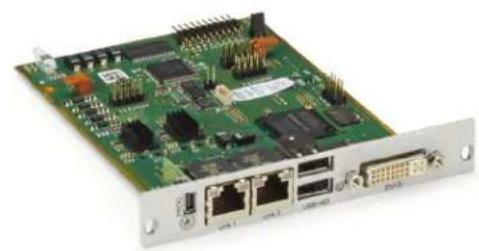
natural_image
Green printed circuit board with multiple ports and connectors (no visible text or symbols)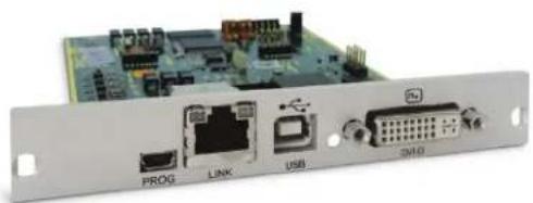
natural_image
Electronic device rear panel with labeled ports (PROG, LINK, USB, SHD) and a green circuit board background (no readable text or symbols beyond labels)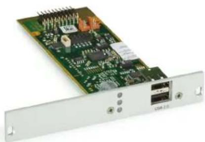
natural_image
Electronic circuit board with ports and connectors, no visible text or symbols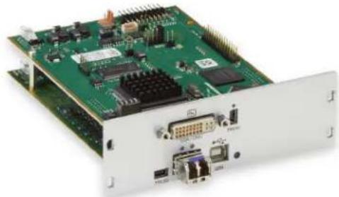
natural_image
Green electronic circuit board with multiple components and connectors (no visible text or symbols)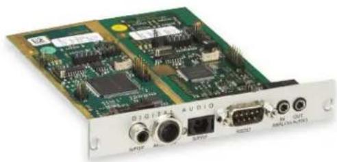
natural_image
Electronic circuit board with various connectors and components (no visible text or symbols)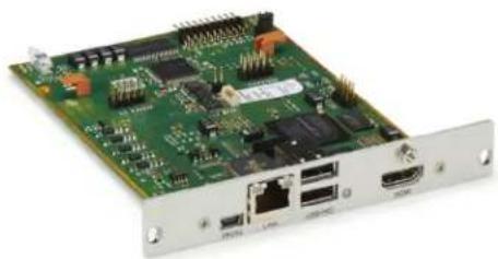
natural_image
Green printed circuit board with ports and connectors (no visible text or symbols)Trademarks Used in this Manual
Black Box and the Double Diamond logo are registered trademarks of BB Technologies, Inc.
Any other trademarks mentioned in this manual are acknowledged to be the property of the trademark owners.
Disclaimer
Black Box Network Services shall not be liable for damages of any kind, including, but not limited to, punitive, consequential or cost of cover damages, resulting from any errors in the product information or specifications set forth in this document and Black Box Network Services may revise this document at any time without notice.
We're here to help! If you have any questions about your application or our products, contact Black Box Tech Support at 877-877-BBOX (2269) or go to blackbox.com and click on "Talk to Black Box." You'll be live with one of our technical experts in less than 60 seconds.
Federal Communications Commission and Industry Canada Radio Frequency Interference Statements
This equipment generates, uses, and can radiate radio-frequency energy, and if not installed and used properly, that is, in strict accordance with the manufacturer's instructions, may cause interference to radio communication. It has been tested and found to comply with the limits for a Class A computing device in accordance with the specifications in Subpart B of Part 15 of FCC rules, which are designed to provide reasonable protection against such interference when the equipment is operated in a commercial environment. Operation of this equipment in a residential area is likely to cause interference, in which case the user at his own expense will be required to take whatever measures may be necessary to correct the interference.
Changes or modifications not expressly approved by the party responsible for compliance could void the user's authority to operate the equipment.
This digital apparatus does not exceed the Class A limits for radio noise emission from digital apparatus set out in the Radio Interference Regulation of Industry Canada.
CE Declaration of Conformity

Disclaimer:
Black Box Network Services shall not be liable for damages of any kind, including, but not limited to, punitive, consequential or cost of cover damages, resulting from any errors in the product information or specifications set forth in this document and Black Box Network Services may revise this document at any time without notice.
1.2 Interconnect Cable 13
1.2.1 CATx 13
1.2.2 Fiber 14
1.3 Supported Peripherals....15
1.3.1 USB-HID Devices 15
1.3.2 USB 2.0 Devicese 15
1.4 Connector Pinouts 15
1.5 Power Supply, Environmental Conditions, Dimensions, and Shipping Weight....23
2. Overview 24
2.1 Application....24
2.2 System Overview....24
2.3 Part Numbers 25
2.3.1 Chassis 25
2.3.2 KVM Extender Modules 26
2.3.3 Upgrade Modules 29
2.3.4 Chassis for Free Configuration....30
2.4 Accessories Upgrade Kits 31
2.5 Accessories....31
2.6 Device Views 32
2.6.1 Compatible Chassis 32
2.6.2 ACX1MT-DHID-C/ACX1MR-DHID-C 41
2.6.3 ACX1MT-VDHID-C /ACX1MR-VDHID-C 41
2.6.4 ACX1MT-DHID-SM/ACX1MR-DHID-SM 42
2.6.5 ACX1MT-DHS-SM/ACX1MR-DHS-SM 42
2.6.6 ACX1MT-VDHID-SM/ACX1MR-VDHID-SM 43
2.6.7 ACX1MT-DHID-2C/ACX1MR-DHID-2C 43
2.6.8 ACX1MT-VDHID-2S/ACX1MR-VDHID-2S 44
2.6.9 ACX1MT-DHID-2S/ACX1MR-DHID-2S 44
2.6.10 ACX1MT-VDHID-2S/ACX1MR-VDHID-2S 45
2.6.11 ACX1MT-DVHID-C/ACX1MR-DVHID-C 45
2.6.12 ACX1MT-DVHID-SM/ACX1MR-DVHID-SM 46
2.6.13 ACX2MT-DLH-C/ACX2MR-DLH-C 46
2.6.14 ACX2MT-DHH-C/ACX2MR-DHH-C 47
2.6.15 ACX2MT-DLH-SM/ACX2MR-DLH-SM 47
2.6.16 ACX2MT-DHH-SM/ACX2MR-DHH-SM 48
2.6.17 ACX2MT-DHHS-SM/ACX2MR-DHHS-SM 48
2.6.18 ACX2MT-DLHS-SM/ACX2MR-DLHS-SM 48
2.6.19 ACX2MT-DLH-2C/ACX2MR-DLH-2C 49
2.6.20 ACX2MT-DHH-2C/ACX2MR-DHH-2C 49
2.6.21 ACX2MT-DLH-SM/ACX2MR-DLH-SM 50
2.6.22 ACX1MT-HDMI-C/ACX1MR-HDMI-C 50
2.6.23 ACX1MT-HDMI/ACX1MR-HDMI 51
2.6.24 ACX1MT-HDM2-C 51
2.6.25 ACX1MT-HDM2-2C/ACX1MR-HDM2-2C 52
2.6.26 ACXMT-HDMI-SM/ACX1MR-HDMI-SM 52
2.6.27 ACX1MT-HDMI-2C/ACX1MR-HDMI-2C 53
2.6.28 ACX1MT-HDM2-SM/ACX1MR-HDM2-SM 53
2.6.29 ACX1MT-HDM2-2S/ACX1MR-HDM2-2S 54
2.6.30 ACX1MR-HDSW-C 54
2.6.31 ACX1MR-HDSW-2C 55
2.6.32 ACX1MR-HDSW-SM 55
2.6.33 ACX1MR-HDSW-2S 56
2.6.34 ACX1MT-HDO-C/ACX1MR-HDO-C 56
2.6.35 ACX1MT-HDO-SM/ACX1MR-HDO-SM 57
2.6.36 ACX2MT-DPH-C/ACX2MR-DPH-C 57
2.6.37 ACX2MT-DPH-SM/ACX2MR-DPH-SM 58
2.6.38 ACX2MT-DPHS-SM/ACX2MR-DPHS-SM 58
2.6.39 ACX2MT-DPH-2C/ACX2MR-DPH-2C 59
2.6.40 ACX2MT-DPH-2S/ACX2MR-DPH-2S 59
3.6.41 ACX2MT-DPHS-2S/ACX2MR-DPHS-2S 60
2.6.42 ACX1MT-HID/ACX1MR-HID 60
2.6.43 ACX1MT-EU/ACX1MR-EU 60
2.6.44 ACX1MT-AR/ACX1MR-AR 61
2.6.45 ACX1MT-ARP/ACX1MR-ARP 61
2.6.46 ACX1MT-DA/ACX1MR-DA 62
2.6.47 ACX1MT-ARH/ACX1MR-ARH 62
2.6.48 ACX1MT-DAH/ACX1MR-DAH 63
2.6.49 ACX1MT-ARE/ACX1MR-ARE 63
2.6.50 ACX1MT-DAE/ACX1MR-DAE 64
2.6.51 ACX1MT-DAX/ACX1MR-DAX....64
2.6.52 ACX1MT-ARD/ACX1MR-ARD 65
2.6.53 ACX1MT-U2-C/ACX1MR-U2-C 65
2.6.54 ACX1MT-U2-SM/ACX1MR-U2-SM 66
2.6.55 ACX1MT-U23-C/ACX1MR-U23-C 66
2.6.56 ACX1MT-U23-SM/ACX1MR-U23-SM 67
2.6.57 ACX2MT-DP4KHS-SM/ACX2MR-DP4KHS-SM 67
2.6.58 ACX2MT-DP4KHS-2S/ACX2MR-DP4KHS-2S....68
2.7 Status LEDs....68
2.7.1 KVM Extender Module Status....68
2.7.2 KVM Extender Module VGA/DVI-I Status 69
2.7.3 Upgrade Module Digital Audio Status....70
2.7.4 Upgrade Module USB-HID Status....71
2.7.5 Upgrade Module USB 2.0 Embedded Status....72
2.7.6 Upgrade Module USB 2.0 Status....73
3. Installation 74
3.1 Package Contents 74
3.2 System Setup 76
3.2.1 KVM Extender Setup....76
3.2.2 Upgrade Modules Setup 76
3.3 Example Applications....77
4. Configuration 80
4.1 Transmission Parameters 80
4.2 DDC Settings....80
4.3 Command Mode 80
4.4 USB-HID Ghosting....81
4.5 Configuration File....82
4.5.1 CPU Units Parameters 82
4.5.2 CON Units Parameters....83
4.5.3 CPU and CON Units Parameters....84
5. Operation 85
5.1 DDC Information Download 85
5.2 Redundant CPU Units Shared Operation....85
6. Troubleshooting 87
6.1 General Failures....87
6.2 Blank Screen....87
6.3 USB-HID 88
6.4 Serial Connection 88
6.5 Analog Audio....89
6.6 Digital Audio 89
6.7 USB-HID Upgrade Module 90
6.8 USB 2.0 Embedded 90
6.9 USB 2.0 Upgrade Module 91
7. Technical Support Information....92
7.1 Contacting Technical Support 92
7.2 Shipping and Packaging....92
8. Glossary 93
Safety Instructions
To ensure reliable and safe long-term operation of your KVM Extender please note the following guidelines:
Installation
- Only use in dry, indoor environments.
- The KVM Extender and the power supply units can get warm. Do not install components in an enclosed space without any airflow.
- Do not place the power supply directly on top of the device.
- Do not obscure ventilation holes.
- Only use power supplies originally supplied with the product or manufacturer-approved replacements. Do not use a power supply if it appears to be defective or has a damaged chassis.
- Connect all power supplies to grounded outlets. In each case, ensure that the ground connection is maintained from the outlet socket through to the power supply's AC power input.
- Do not connect the link interface to any other equipment, particularly network or telecommunications equipment.
• Take any required ESD precautions.
NOTE: To disconnect the device completely from the electric circuit, all power cables have to be removed.
Repair
- Do not attempt to open or repair a power supply unit.
- Do not attempt to open or repair the KVM Extender. There are no user serviceable parts inside.
- Please contact Black Box Technical Support at 724-746-5500 or info@blackbox.com if there is a fault.
1. Specifications
1.1 Interfaces
1.1.1 DVI-D Single Link
The video interface supports the DVI-D protocol. All signals that comply with the DVI-D Single-Link specification can be transmitted. This includes, for example, monitor resolutions such as 1920 x 1200 @ 60 Hz, Full HD (1080p), or 2K HD (up to 2048 x 1152). Data rate is limited to 165 Megapixels per second.
1.1.2 DVI-D Dual Link
The video interface supports the DVI-D protocol. All signals that comply to DVI-D Dual Link norm can be transmitted. This includes monitor resolutions up tp 2560x2048@60Hz. Data rate is limited to 330 MPixel/s.
1.1.3 DVI-I Single Link
The video interface supports the DVI-I protocol. All analog (VGA) or digital (DVI) signals that comply with the DVI-I Single-Link specification can be transmitted. This includes monitor resolutions for VGA up to 1920 x 1200 @ 60 Hz, and monitor resolutions for DVI-I up to Full HD (1080p) or for DVI-D 2K HD (up to 2048 x 1152). Data rate is limited to 165 Megapixels per second.
NOTE: Transmission of interlaced video signals, such as 1920 x 1080i, cannot be guaranteed.
1.1.4 HDMI Single Link
Video
The audio/video interface can transmit monitor resolutions such as 1920 x1200 @60 Hz, Full HD (1080p) or 2K HD (up to 2048 x 1152). Data rate is limited to 165 MPixel/s and 8 bit.
Audio
The audio format PCM can be transmitted through the interface.
- Standards: Stereo Linear Pulse Code Modulation (LPCM)
- Bit Depth: 16 bit
• Sample Rate: Up to 96 kHz
Further audio formats will be supported in the future through a firmware update.
3D
The interface is compatible to 3D, so the 3D formats Side-by-Side and Top-and-Bottom can be transmitted.
NOTE: HDCP coded content is currently not supported.
1.1.5 DisplayPort
Video
The video interface supports the DisplayPort 1.2 standard. All signals that comply with this standard can be transmitted. This includes monitor resolutions up to 2560 x 2048@ 60 Hz or 3840 x 2160 @30 Hz. Data rate is limited to 330 MPixel/s.
Audio
Various audio formats can be transmitted through the interface.
• Standards: Stereo Linear Pulse Code Modulation (LPCM), DTS, DTS-HD (5.1), Dolby Digital, Dolby Digital Plus (5.1)
- Bit Depth: 16 to 24 bit
• Sample-Rate: 32 to 192 kHz
1.1.6 USB-HID
Our devices with an USB-HID interface support a maximum of two devices compliant with the USB-HID protocol. Each USB-HID port provides a maximum current of 100 mA.
Keyboard
Compatible with most USB keyboards. Certain keyboards with additional functions may require custom firmware to operate. Keyboards with an integral USB hub (such as Mac ^® keyboards) can also be supported using non-USB HID cards.
Mouse
Compatible with most 2-button, 3-button, and scroll mice.
Other USB-HID devices
The proprietary USB emulation also supports certain other USB-HID devices, such as specific touchscreens, graphics tablets, bar-code scanners or special keyboards. Support cannot be guaranteed, however, for every USB-HID device.
NOTE: Only two USB-HID devices are supported concurrently, such as keyboard and mouse or keyboard and touchscreen. A hub is allowed, but it does not increase the number of HID devices allowed.
To support other USB "non-HID" devices, such as scanners, Web cams, or memory devices, choose our devices with transparent USB support.
1.1.7 PS/2
Our devices with PS/2 interface support the use of a PS/2 keyboard and mouse.
Keyboard
Compatible with most PS/2 keyboards, even with various special keyboards. Certain keyboards with additional functions can be run with special firmware.
Mouse
Compatible with most 2-button, 3-button and scroll mice.
1.1.8 USB 2.0 (transparent)
DKM Modular Extender models with transparent USB 2.0 support allow the connection of all types of USB 2.0 devices (without restriction). USB 2.0 data transfer is supported, depending on the upgrade module, with high-speed USB (max. 480 Mbps) or full-speed USB (max. 36 Mbps).
Each USB 2.0 port provides a maximum current of 500 mA (high power). When using a USB high speed interface with 4 USB ports, respectively 2 connectors provides a maximum of 500 mA (high power) and 2 connectors a maximum of 100 mA.
1.1.9 RJ-45 (Interconnect)
For CATx communications, the extender requires a 1000BASE-T connection.
Connector wiring must comply with EIA/TIA-568-B (1000BASE-T), with RJ-45 connectors at both ends. All four cable wire pairs are used.
1.1.10 Fiber SFP Type LC (Interconnect)
The communication of fiber devices is performed via Gigabit SFPs that have to be connected to suitable fibers fitted with type LC connectors.
NOTE: The correct function of the device can only be guaranteed with SFPs provided by Black Box.
CAUTION: SFP modules can be damaged by electrostatic discharge (ESD).
When handling, take care not to damage devices.
1.1.11 Serial Interface
The serial interface option supports a full-duplex transmission with a real hardware handshake up to a baud rate of 19,200.
The CON module is cabled as DTE (Data Terminal Equipment, such as CPU output) and can be connected directly to DCE (Data Communication Equipment) devices.
- A touchscreen can be connected directly to the CON module.
- To connect to a serial printer (or any other DTE instead of DCE device), you need a null-modem cable (cross-over cable) between the CON module and the device.
Operation of several devices:
The serial interface transmits six signals (three for each direction). Normally, four of the six signals are handshake signals (in addition to RxD and TxD). The following configurations, however, are possible using special adapter splitting cables:
• Three single 2-wire transmissions.
- Two transmissions with a handshake signal.
- A serial mouse and a single 2-wire transmission.
In this case, choose X-ON/X-OFF software handshake for traffic control at the printer and PC.
- Connection Format: DTE (Data Terminal Equipment)
• Speed: Up to 19,200 Baud
• Data Format: Format independent - Data Transmission:
- RxD (Receive Data)
- TxD (Transmit Data)
- Traffic Control: The following signals are transmitted (hardware handshake):
- RTS (Request To Send)
- CTS (Clear To Send)
- DTR (Data Terminal Ready)
- DSR (Data Set Ready)
1.1.12 Serial Interface RS-422
KVM Extenders with a serial interface RS-422 (DB9) support a differential full-duplex transmission up to a Baud rate of 115,200 Baud.
The CPU unit is designed as controlling device and can, for example, be connected directly to video or media servers.
The CON unit is designed as a controlled device and so can be connected directly to remote controllers.
Table 1-1. Serial interface specifications.
| Specification Description | |
| Connection Format DTE (Data Terminal Equipment) | |
| Speed Up to 115,200 baud | |
| Data Format Format independent | |
| Data Transmission | • RxD (Receive Data)• TxD (Transmit Data) |
| Traffic Control | The following signals are transmitted (hardware handshake):• RTS (Request to Send)• CTS (Clear to Send)• DTR (Data Terminal Ready)• DSR (Data Set Ready) |
1.1.13 Analog Audio Interface
The Analog Audio option supports a bidirectional stereo audio transmission, in nearly CD quality.
The audio interface is a "line level" interface and it is designed to transmit the signals of a sound card (or another "line level" device) as well as to allow the connection of active speakers to the CON module.
Stereo audio can be transmitted bidirectionally at the same time.
Connection of a microphone:
Connect the microphone to the "audio" input of the CON module. There are two ways to establish this connection:
- The output of the CPU module is connected with the microphone input of the sound card (red). Adjust the sound card to provide an additional amplification (20 dB).
- The output of the CPU module is connected to the audio input of the sound card (blue). Choose this connection if the microphone has its own pre-amplifier.
NOTE: The CON module can do the pre-amplification of the microphone as well. Open the CON module, locate the "MIC" jumper on the audio board and close the pins.
Table 1-2. Analog audio specifications.
| Specification Description |
| Transmission Format Digitized virtually CD-quality audio (16-bit, 38.4 kHz) |
| Signal Level Line-level (5-volt peak-peak maximum) |
| Input Impedance 47 kOhm |
| Connections CPU Unit (2) 3.5-mm stereo audio plug (audio in and audio out) |
| Connections CON Unit (2) 3.5-mm stereo audio plug (audio in and audio out) |
1.1.14 Digital Audio Interface
The digital audio option supports the unidirectional transmission of digital audio data.
Up to three sources can be connected to the CPU module. The active source is transmitted. If several sources are active, the XLR signal takes priority, otherwise the first active signal.
Up to three sinks can be connected to the CON module. The signal is available at all outputs concurrently.
DKM Modular Extender with digital audio option includes a built-in sample rate converter that provides predefined sample frequencies at the CON module's output.
The user can set the following parameters directly via a configuration file:
- Activate or deactivate sample rate converter
- Set sample frequency of the sample rate converter. The following sample frequencies are available:
-32.0 kHz
-44.1 kHz
-48.0 kHz
-96.0 kHz - To deactivate the sample rate converter, write SRC_NONE in the Config.txt file of the CPU unit.
Table 1-3. Digital audio interface specifications.
| Specification Description | |
| Compatibility AES/EBU, S/PDIF, EIAJCP1201, IEC 60958 | |
| Standards Dolby digital, DTS, PCM | |
| CPU Unit (Inputs) | Mini XLR (AES/EBU; symmetrical lockable)Coaxial (S/PDIF; RCA, Cinch)Optical (S/PDIF, TOSLINK *) |
| CON Unit (Outputs) | Mini XLR (AES/EBU; symmetrical, lockable)Coaxial (S/PDIF, RCA, Cinch)Optical (S/PDIF, TOSLINK) |
1.2 Interconnect Cable
1.2.1 CATx
NOTE: A point-to-point connection is required. Operation with several patch fields is possible. Routing over an active network component, such as an Ethernet hub, router, or switch, is not allowed.
- Avoid routing CATx cables along power cables.
- If the site has 3-phase AC power, make sure that the CPU module and CON module are on the same phase.
CAUTION: To maintain regulatory EMC compliance, you must use correctly installed shielded CATx cable throughout the interconnection link. Also, all CATx cables need to have ferrites on both cable ends close to the device.
Type of Interconnect Cable
The DKM Modular Extender requires interconnect cabling specified for Gigabit Ethernet (1000BASE-T). The use of solid-core (24 AWG), shielded, CAT5e (or better) is recommended.
Table 1-4. CATx interconnect cable specifications.
| Parameter Description | |
| CATx solid-core cable 24 AWG | S/UTP (CAT5e) cable according to EIA/TIA-568-B. Four pairs of 24 AWG wires. Connection according to EIA/TIA-568-B (1000BASE-T). |
| CATx patch cable 26/8 AWG | S/UTP (CAT5e) cable according to EIA/TIA-568-B. Four pairs of 26/8 AWG wires. Connection according to EIA/TIA-568-B (1000BASE-T). |
NOTE: You can use flexible cables (patch cables) type 26/8 AWG; however, but you'll only get half the maximum possible extension distance (Table 1-5).
Maximum Acceptable Cable Length
Table 1-5. Maximum acceptable CATx cable length.
| Cable Type Maximum Length | |
| Solid-conductor 24 AWG CATx cable 400 feet (140 m) | |
| Stranded-conductor 26/28 or 27/28 AWG or CATx cable 200 feet (70 m) |
1.2.2 Fiber
NOTE: A point-to-point connection is necessary. Operation with multiple patch panels is allowed. Routing over active network components, such as Ethernet hubs, switches, or routers, is not allowed.
Type of Interconnect Cable
(Cable notations according to VDE)
Table 1-6. Fiber cable specifications.
| Cable Type Description | |
| Single-mode fiber 9 μm | • Duplex.• Indoor patch cable (EFN092) |
| Multimode fiber 50 μm | • Duplex.• Indoor patch cable (EFN6020) |
| Multimode fiber 62.5 μm | • Duplex.• Indoor patch cable (EFN116-LCLC) |
Table 1-7. Maximum acceptable fiber cable length specifications.
| Cable Type Description |
| Single-mode fiber 9 μm 32,800 feet (10,000 m) |
| Single-mode 9μm XV 5,000 m (16,400 ft) |
| Multimode fiber 50 μm (OM3) 3280 feet (1000 m) |
| Multimode fiber 50 μm 1300 feet (400 m) |
| Multimode fiber 62.5 μm 650 feet (200 m) |
NOTE: If you use single-mode SFPs with multimode fibers, you can normally double the maximum acceptable cable length.
Connector type
The Modular Extenders have fiber LC connectors.
1.3 Supported Peripherals
1.3.1 USB-HID Devices
The DKM Modular Extender will support most USB-HID devices, including the vast majority of keyboards and mice currently on the market. Many other kinds of HID devices such as bar-code scanners and touchscreens may also be compatible.
It is not possible to guarantee support for all available USB-HID devices. In certain cases, you may need custom firmware.
USB-HID (and other) devices that are not supported as standard will normally operate with our devices featuring transparent USB support.
NOTE: Concurrent operation of more than two USB-HID devices is not possible even if you use a USB hub.
1.3.2 USB 2.0 Devices
DKM Modular Extender models featuring a transparent USB 2.0 connection use Extreme USB Technology. This technology supports all types of USB 2.0 devices; however, we cannot guarantee compatibility with every device on the market. Please contact Black Box Technical Support at 724-746-5500 or info@blackbox.com if any issues are found.
1.4 Connector Pinouts
Connector DVI Single-Link
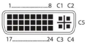
Figure 1-1. DVI-D single-link connector.
Table 1-8. DVI-D single-link connector pinout.
| Pin Signal Pin Signal Pin Signal | |||||
| 1 | TMDS data 2- | 9 | TMDS data 1- | 17 | TMDS data 0- |
| 2 | TMDS data 2+ | 10 | TMDS data 1+ | 18 | TMDS data 0+ |
| 3 | TMDS data 2 GND | 11 | TMDS data 1 GND | 19 | TMDS data 0 GND |
| 4 | Not connected | 12 | Not connected | 20 | Not connected |
| 5 | Not connected | 13 | Not connected | 21 | Not connected |
| 6 | DDC input (SCL) | 14 | +5 VDC high impedance | 22 | TMDS clock GND |
| 7 | DDC output (SDA) | 15 | GND | 23 | TMDS clock + |
| 8 | Internal use | 16 | Hot-plug recognition | 24 | TMDS clock - |
| C1 | Internal use | — | — | C3 | Internal use |
| C2 | Not connected | C5 | GND | C4 | Internal use |
Connector DVI Dual-Link
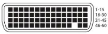
Figure 1-2. DVI-D dual link connector.
Table 1-9. DVI-D dual-link connector pinout.
| Pin Signal Pin Signal Pin Signal | |||||
| 1 | GND | 21 | RX5_U | 41 | GND |
| 2 | Not connected | 22 | GND | 42 | GND |
| 3 | Not connected | 23 | Not connected | 43 | GND |
| 4 | GND | 24 | Not GND | 44 | BRXC_N |
| 5 | 5V DVI | 25 | RX2_P | 45 | BRXC_P |
| 6 | DDC SCL | 26 | RX2_N | 46 | GND |
| 7 | DDC SDA | 27 | RX1_P | 47 | Not connected |
| 8 | GND | 28 | RX1_N | 48 | Not connected |
| 9 | BDDC SDA | 29 | RX0_P | 49 | GND |
| 10 | BDDC SCL | 30 | RX0_N | 50 | Not connected |
| 11 | B5V DVI | 31 | RXC_P | 51 | Not connected |
| 12 | GND | 32 | RXC_N | 52 | GND |
| 13 | Not connected | 33 | GND | 53 | Not connected |
| 14 | Not connected | 34 | GND | 54 | GND |
| 15 | GND | 35 | GND | 55 | Not connected |
| 16 | RX3_P | 36 | HPD | 56 | Not connected |
| 17 | RX3_N | 37 | Not connected | 57 | GND |
| 18 | RX4_P | 38 | Not connected | 58 | Not connected |
| 19 | RX4_N | 39 | Not connected | 59 | Not connected |
| 20 | RX5_P | 40 | BHPDT | 60 | GND |
Connector DVI-I Single-Link
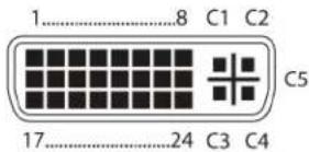
Figure 1-3. DVI-I connector.
Table 1-10. DVI-I single-link connector pinout.
| Pin Signal Pin Signal Pin Signal | |||||
| 1 | TMDS data 2- | 9 | TMDS data 1- | 17 | TMDS data 0- |
| 2 | TMDS data 2+ | 10 | TMDS data 1+ | 18 | TMDS data 0+ |
| 3 | TMDS data 2 GND | 11 | TMDS data 1 GND | 19 | TMDS data 0 GND |
| 4 | Not connected | 12 | Not connected | 20 | Not connected |
| 5 | Not connected | 13 | Not connected | 21 | Not connected |
| 6 | DDC input (SCL) | 14 | +5 VDC high impedance | 22 | TMDS clock GND |
| 7 | DDC output (SDA) | 15 | GND | 23 | TMDS clock + |
| 8 | V-sync | 16 | Hot-plug recognition | 24 | TMDS clock - |
| C1 | Red signal | — | — | C3 | Blue signal |
| C2 | Green signal | C5 | GND | C4 | H-sync |
Connector HDMI Single-Link
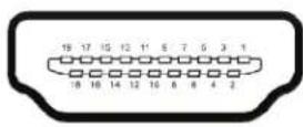
Figure 1-4. HDMI single-link connector.
Table 1-11. HDMI single-link connector pinout.
| Pin | Signal | Pin | Signal | Pin | Signal |
| 1 | T.M.D.S data 2 + | 8 | T.M.D.S data 0 GND | 15 | DDC Input (SCL) |
| 2 | T.M.D.S data 2 GND | 9 | T.M.D.S data 0 - | 16 | DDC Output (SDA) |
| 3 | T.M.D.S data 2 - | 10 | T.M.D.S clock + | 17 | DDC/CEC/HEC GND |
| 4 | T.M.D.S data 1 + | 11 | T.M.D.S clock GND | 18 | +5VDC high impedance |
| 5 | T.M.D.S data 1 GND | 12 | T.M.D.S clock - | 19 | Hot Plug recognition |
| 6 | DDC Input (SCL) | 13 | CEC | — | — |
| 7 | T.M.D.S data 1 - | 14 | HEC data - | — | — |
DisplayPort connector
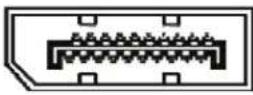
Figure 1-5. HDMI single-link connector.
Table 1-12. HDMI single-link connector pinout.
| Pin Signal Pin Signal Pin Signal | |||||
| 1 | ML-LANE3(N) | 8 | GND | 15 | AUX CH(P) |
| 2 | GND | 9 | ML-LANE1(P) | 16 | GND |
| 3 | ML-LANE3(P) | 10 | ML-LANE0(N) | 17 | AUX CH(N) |
| 4 | ML-LANE2(N) | 11 | GND | 18 | Hot Plug Detect |
| 5 | GND | 12 | ML-LANE0(P) | 19 | Power Out Return |
| 6 | ML-LANE2(P) | 13 | Config1/GND | 20 Power Out (not connected) | |
| 7 | ML-LANE1(N) | 14 | Config2/GND | — | — |
Connector USB Type B

Figure 1-6. USB Type B connector.
Table 1-13. USB Type B connector pinout.
| Pin Signal Color |
| 1 VCC (+5 VDC) Red |
| 2 Data - White |
| 3 Data + Green |
| 4 GND Black |
Connector USB Type A
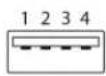
Figure 1-7. USB Type A connector.
Table 1-14. USB Type A connector pinout.
| Pin Signal Color |
| 1 VCC (+5 VDC) Red |
| 2 Data - White |
| 3 Data + Green |
| 4 GND Black |
Connector Mini USB Type B

Figure 1-8. Mini USB Type B connector.
Table 1-15. Mini USB Type B connector pinout.
| Pin Signal Color |
| 1 VCC (+5 VDC) Red |
| 2 Data - White |
| 3 Data + Green |
| 4 Not connected — |
| 5 GND Black |
Connector PS/2

Figure 1-9. PS/2 connector.
Table 1-16. PS/2 connector pinout.
| Pin Signal |
| 1 Data |
| 2 GND |
| 3 VCC (+ 5VDC) |
| 4 CLK |
| 5 Not connected |
| 6 Not connected |
RJ-45 connector
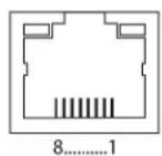
Figure 1-10. RJ-45 connector.
Table 1-17. RJ-45 connector pinout.
| Pin Signal Pin Signal |
| 1 D1+ 5 D3- |
| 2 D1- - 6 D2- |
| 3 D2+ 7 D4+ |
| 4 D3+ 8 D4- |
Fiber SFP Type LC
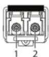
Figure 1-11. SFP Type LC connector.
Table 1-18. SFP Type LC connector pinout.
| Pin Signal |
| 1 Data OUT |
| 2 Data IN |
Power Supply
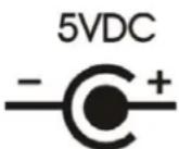
Figure 1-12. Power supply label..
Table 1-19. Power supply connector pinout.
| Pin Signal |
| Inside VCC (+5 VDC) |
| Outside GND |
DB9 (Serial) RS-232
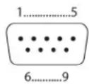
Figure 1-13. DB9 serial connector.
Table 1-20. DB9 serial RS-232 connector pinout.
| Pin Signal Pin Signal | ||
| 1 Not connected 6 DSR | ||
| 2 RxD 7 RTS | ||
| 3 TxD 8 CTS | ||
| 4 DTR 0 Not connected | ||
| 5 GND — — |
DB9 (Serial) RS-422 Controlled Device
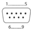
Figure 1-14. DB9 serial connector.
Table 1-21. DB9 serial RS-422 connector pinout, controlled device.
| Pin Signal Pin Signal | |
| 1 GND 6 Rx GND | |
| 2 RxA 7 RxB | |
| 3 TxB | 8 TxA |
| 4 Tx GND | 0 Not connected |
| 5 Not connected — — | |
DB9 (Serial) RS-422 Controlling Device
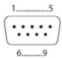
Figure 1-15. DB9 serial connector.
Table 1-22. DB9 serial RS-422 connector pinout, controlling device.
| Pin Signal Pin Signal | |
| 1 GND 6 Tx GND | |
| 2 TxA 7 TxB | |
| 3 RxB 8 RxA | |
| 4 Rx GND 0 Not connected | |
| 5 Not connected — — |
3.5-mm Stereo Jack Plug

Figure 1-16. 3.5-mm stereo jack plug.
Table 1-23. 3.5-mm stereo jack plug pinout.
| Pin Signal |
| 1 GND |
| 2 Audio IN/OUT L |
| 3 Audio IN/OUT R |
RCA (Cinch)

Figure 1-17. RCA connector.
Table 1-24. RCA connector pinout.
| Pin Signal |
| 1 GND |
| 2 Data IN/OUT |
Mini-XLR
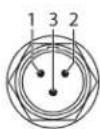
Figure 1-18. Mini XLR connector.
Table 1-25. Mini XLR connector pinout.
| Pin Signal |
| 1 GND |
| 2 Data + |
| 3 Data - |
TOSLINK
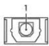
Figure 1-19. TOSLINK connector.
Table 1-26. TOSLINK connector pinout.
| Pin Signal |
| 1 Data IN/OUT |
1.5 Power Supply, Environmental, Dimensions, and Shipping Weight
Table 1-27. Power supply, environmental, dimensions, and shipping weight specifications.
| Power | Basic modules: Single-head devices: 800 mA max., VGA: 900 mA max.; Upgrade modules: Analog audio/serial 300 mA max., Digital audio: 300 mA max., USB-HID: 300 mA max.; USB 2.0 modules: 2500 mA max. |
| Environmental | Temperature Tolerance: Operating: +41 to +113°F (+5 to +45°C) Storage Temperature: -13 to +140°F (-25 to +60°C); Relative Humidity (Max.): 80% non-condensing |
| Dimensions | CPU Module/CON Module: 1.6"H x 5.7"W x 5.6"D (4.1 x 14.5 x 14.2 cm) |
| Shipping Weight | CPU Module/CON Module: 0.6 lb. (0.3 kg) |
2. Overview
2.1 Application
The DKM Modular Extender is used to increase the distance between a source (computer, CPU) and its console (keyboard, mouse, and other peripheral devices). It's designed for use with CATx (twisted-pair) interconnect cables or fiber interconnect cables.
The DKM Modular Extender with CATx interconnect cables won't work between buildings where you should use a fiber optic based product instead.
The DKM Modular Extender with fiber interconnect cables also works with applications in environments with a great deal of electromagnetical interference. Electromagnetical interference can limit the maximum distance und reliability.
The DKM Modular Extender is fully compatible with the DKM Compact Extender (ACX1T/ACX1R series).
2.2 System Overview
The DKM Modular Extender consists of at least one CPU module and one console (CON) module. A 2-, 4-, or 6-slot modular case holds the modules. The DKM Modular cases (2-slot, 4-slot, or 6-slot) are installed at the CPU (transmitter) and CON (receiver) site.
The CPU module connects directly to the source (computer, CPU) using the supplied cables. The CON module connects to the console (monitor, keyboard, and mouse). The CPU module and the CON modules communicate with each other through the interconnect cables. Figure 2-1 shows a typical system application. Table 2-1 describes the components shown in the diagram.
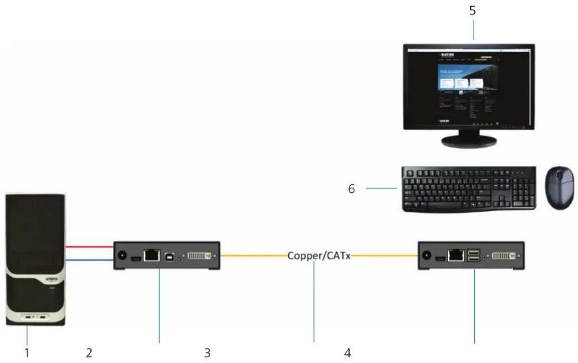
flowchart
graph LR
    A["CPU"] -->|1| B["Switch"]
    B -->|2| C["Copper/CATx"]
    C -->|3| D["Computer"]
    C -->|4| E["Computer"]
    C -->|5| F["Monitor"]
Figure 2-1. System diagram.
Table 2-1. System components.
| Number Component |
| 1 Source (computer, CPU) |
| 2 DKM Modular Extender CPU unit |
| 3 Interconnect cable |
| 4 DKM Modular Extender CON unit |
| 5 Console (monitor, keyboard, mouse) |
| 6 USB-HID devices (option, only with four USB-HID devices) |
NOTE: See Section 3.3 for installation examples.
2.3 Part Numbers
Part numbers for connections via CATx or fiber cable:
All mentioned devices are available in the following versions:
- Connection via CATx cable (xx = "C")
- Connection via single-mode fiber cable (x = "SM")
Part numbers for CPU module and CON module:
IMPORTANT! The part numbers for the CPU module and the CON module can be derived from the part number of the complete device.
• CPU module: ACX1MT
• CON module: ACX1MR
NOTE: All devices in the ACX1MT/R DKM Modular series are compatible with the devices of the DKM Compact Extenders (ACX1T/R series).
2.3.1 Chassis
NOTE: For information about the chassis, see the Chassis User Manual.
2.3.2 KVM Extender Modules
Table 2-2. KVM Extender modules.
| Part Number Description | |
| ACX1MT-DHID-C | Single-Head module for (1) DVI-D Single link |
| ACX1MR-DHID-C | |
| ACX1MT-VDHID-C | Single-Head module for (1) DVI-I input (VGA / DVI), Single-Link (up to 1920 x 1200) with (2) USB-HID |
| ACX1MR-VDHID-C | |
| ACX1MT-DHID-SM | Single-Head module for (1) DVI-D Single Link (up to 1920 x 1200) with (2) USB-HID |
| ACX1MR-DHID-SM | |
| ACX1MT-DHS-SM | Single-Head module for (1) DVI-D Single Link (up to 1920 x 1200) with (2) USB-HID |
| ACX1MR-DHS-SM | |
| ACX1MT-VDHID-SM | Single-Head module for (1) DVI-I (VGA/DVI onboard) Single-Link (up to 1920 x 1200) with (2) USB-HID |
| ACX1MR-VDHID-SM | |
| ACX1MT-DHID-2C | Single-Head module for (1) DVI-D Single Link (up to 1920 x 1200) with (2) USB-HID and redundant connector for interconnect cables |
| ACX1MR-DHID-2C | |
| ACX1MT-VDHID-2C | Single-Head module for (1) DVI-I (VGA/DVI) Single Link (up to 1920 x 1200) with (2) USB-HID |
| ACX1MR-VDHID-2C | |
| ACX1MT-DHID-2S | Single-Head module for (1) DVI-D Single Link (up to 1920 x 1200) with (2) USB-HID and redundant connector for interconnect cables |
| ACX1MR-DHID-2S | |
| ACX1MT-VHID-2S | Single-Head module for (1) DVI-I (VGA/DVI onboard) Single-Link (up to 1920 x 1200) with (2) USB-HID and redundant connector for interconnect cables |
| ACX1MR-VHID-2S | |
| ACX1MT-DVHID-C | Single-Head module for (1) DVI-I (VGA/DVI) Single Link (up to 1920x1200) with (2) USB-HID |
| ACX1MR-DVHID-C | |
| ACX1MT-DVHID-SM | Single-Head module for (1) DVI-I (VGA/DVI) Single Link (up to 1920 x 1200) with (2) USB-HID |
| ACX1MR-DVHID-SM | |
| ACX2MT-DLH-C | Single-Head module for (1) DVI-D Dual Link (up to 2560 x 1600), (2) USB-HID |
| ACX2MR-DLH-C | |
| ACX2MT-DHH-C | Dual-Head module for (2) DVI-D Single Link (up to 1920 x 1200), (2) USB-HID |
| ACX2MR-DHH-C | |
| ACX2MT-DLH-SM | Single-Head module for (1) High-Speed DVI-D Dual Link (up to 2560 x 1600), (2) USB-HID |
| ACX2MR-DLH-SM | |
| ACX2MT-DLHS-SM | Single-Head module for (1) High-Speed DVI-D Dual Link (up to 2560 x 1600), (2) USB-HID |
| ACX2MR-DLHS-SM |
Table 2-2. KVM Extender modules (continued).
| Part Number Description | |
| ACX2MT-DHHS | Dual-Head module for (2) DVI-D High-Speed Single Link (up to 1920 x 1200), (2) USB-HID |
| ACX2MR-DHHS | |
| ACX2MT-DHH-SM | Dual-Head module for (2) DVI-D Single Link (up to 1920 x 1200), (2) USB-HID |
| ACX2MR-DHH-SM | |
| ACX2MT-DLH-2C | Dual-Head module for (2) DVI-D Single Link (up to 1920 x 1200), (2) USB-HID and redundant connector for interconnect cables. |
| ACX2MR-DLH-2C | |
| ACX2MT-DHH-2C | Dual-Head module for (2) DVI-D Single Link (up to 1920 x 1200), (2) USB-HID and redundant connector for interconnect cables. |
| ACX2MR-DHH-2C | |
| ACX1MT-HDMI-C | Single-Head module for (1) HDMI Single Link (up to 1920 x 1200), (2) USB-HID |
| ACX1MR-HDMI-C | |
| ACX1MT-HDMI-2C | Single-Head module for (1) HDMI Single Link (up to 1920 x 1200), (2) USB-HID |
| ACX1MR-HDMI-2C | |
| ACX1MT-HDM2-2C | Single-Head KVM Extender for (1) HDMI Single Link (up to 1920 x 1200), (2) USB-HID and local output and redundant connector for interconnect cables |
| ACX1MT-HDMI-SM | Single-Head module for (1) HDMI Single Link (up to 1920 x 1200), (2) USB-HID |
| ACX1MR-HDMI-SM | |
| ACX1MT-HDMI-2C | Single-Head KVM Extender for (1) HDMI Single Link (up to 1920 x 1200), (2) USB-HID and local output and redundant connector for interconnect cables |
| ACX1MR-HDMI-2C | |
| ACX1MT-HDM2-2C | Single-Head KVM Extender for (1) HDMI Single Link (up to 1920 x 1200) with local HDMI output, (2) USB-HID, and redundant connector for interconnect cables |
| ACX1MT-HDMI-SM | Single-Head KVM Extender for (1) HDMI Single Link (up to 1920 x 1200), (2) USB-HID, KVM switch for local workstation and redundant connector for interconnect cables |
| ACX1MR-HDMI-SM | |
| ACX1MT-HDMI-2C | Single-Head KVM Extender for (1) HDMI Single Link (up to 1920 x 1200), (2) USB-HID, KVM switch for local workstation |
| ACX1MR-HDMI-2C | |
| ACX1MT-HDM2-SM | Single-Head KVM Extender for (1) HDMI Single Link (up to 1920 x 1200), (2) USB-HID with local HDMI output |
| ACX1MT-HDM2-2S | Single-Head KVM Extender for (1) HDMI Single Link (up to 1920 x 1200), (2) USB-HID with local HDMI output and redundant connector for interconnect cables |
| ACX1MR-HDSW-C | Single-Head KVM Extender for (1) HDMI Single Link (up to 1920 x 1200), (2) USB-HID with built-in KVM switch on CON unit |
| ACX1MT-HDSW-2C | Single-Head KVM Extender for (1) HDMI Single Link (up to 1920 x 1200), (2) USB-HID with built-in KVM switch on CON unit and redundant connectors for interconnect cables |
| ACX1MR-HDSW-SM | Single-Head KVM Extender for (1) HDMI Single Link (up to 1920 x 1200), (2) USB-HID with built-in KVM switch on CON unit |
| ACX1MR-HDSW-2S | Single-Head KVM Extender for (1) HDMI Single Link (up to 1920 x 1200), (2) USB-HID with built-in KVM switch on CON unit and redundant connectors for interconnect cables |
| ACX1MT-HDO-C | Single-Head KVM Extender for (1) HDMI Single Link (up to 1920 x 1200) |
| ACX1MR-HDO-C | |
| ACX1MT-HDO-SM | Single-Head KVM Extender for (1) HDMI Single Link (up to 1920 x 1200) |
| ACX1MR-HDO-SM | |
| ACX2MT-DPH-C | Single-Head module for (1) DisplayPort with (2) USB-HID |
| ACX2MR-DPH-C | |
| ACX2MT-DPH-SM | Single-Head module for (1) DisplayPort with (2) USB-HID |
| ACX2MR-DPH-SM | |
| ACX2MT-DPHS-SM | Single-Head module for (1) DisplayPort with (2) USB-HID |
| ACX2MR-DPHS-SM | |
| ACX2MT-DPH-2C | Single-Head module for (1) DisplayPort with (2) USB-HID and redundant connector for interconnect cables |
| ACX2MR-DPH-2C | |
| ACX2MT-DPH-2S | Single-Head module for (1) DisplayPort with (2) USB-HID and redundant connector for interconnect cables |
| ACX2MR-DPH-2S | |
| ACX2MT-DPHS-2S | Single-Head module for (1) DisplayPort with (2) USB-HID and redundant connector for interconnect cables |
| ACX2MR-DPHS-2S | |
| ACX1MT-U23-C | USB 2.0 upgrade module with (4) USB 2.0 HID |
| ACX1MR-U23-C | |
| ACX1MT-U23-SM | USB 2.0 over fiber upgrade module with (4) USB 2.0 HID |
| ACX1MR-U23-SM | |
| ACX2MT-DP4KHS-SM | Single-Head high-speed module for (1) DisplayPort 4K with (2) USB 2.0 HID |
| ACX2MR-DP4KHS-SM | |
| ACX2MT-DP4KHS-2S | Single-Head high-speed module for (1) DisplayPort 4K with (2) USB 2.0 HID |
| ACX2MR-DP4KHS-2S |
2.3.3 Upgrade Modules
Table 2-3. Upgrade modules.
| Part Number Description | |
| ACX1MT-HID | Upgrade module with (2) USB-HID |
| ACX1MR-HID | |
| ACX1MT-EU | Upgrade module with (2) USB 2.0 |
| ACX1MR-EU | |
| L/R474-BUE | Upgrade module with Analog Audio (bidirectional) and (2) USB 2.0 |
| ACX1MT-AR | Upgrade module with analog audio/serial (bidirectional) |
| ACX1MR-AR | |
| L/R474-BSX | Upgrade module with Analog Audio/Serial RS422 (bidirectional) |
| ACX1MT-ARP | Upgrade module with Analog Audio / Serial RS232 (bidirectional) and PS/2 |
| ACX1MR-ARP | |
| L/R474-BXP | Upgrade module with PS/2 (only available with upgrade module Analog Audio/Serial) |
| ACX1MT-DA | Upgrade module with digital audio (unidirectional) |
| ACX1MR-DA | |
| ACX1MT-ARH | Upgrade module with analog audio/serial (bidirectional) and (2) USB-HID |
| ACX1MR-ARH | |
| ACX1MT-DAH | Upgrade module with digital audio (unidirectional) and (2) USB-HID |
| ACX1MR-DAH | |
| ACX1MT-ARE | Upgrade module with Analog Audio/Serial RS232 (bidirectional) and (2) USB 2.0 |
| ACX1MR-ARE | |
| ACX1MT-DAE | Upgrade module with Digital Audio (unidirectional) and (2) USB 2.0 |
| ACX1MR-DAE | |
| ACX1MT-DAX | Upgrade module with digital audio (bidirectional) |
| ACX1MR-DAX | |
| ACX1MR-ARD | Upgrade module with digital audio (unidirectional) and analog audio/serial (bidirectional) |
| ACX1MT-ARD | |
| ACX1MT-U2-C | USB 2.0 upgrade module with (4) USB 2.0 |
| ACX1MR-U2-C | |
| ACX1MT-U2-SM | USB 2.0 upgrade module with (4) USB 2.0 |
| ACX1MR-U2-SM | |
2.3.4 Chassis for Free Configuration
Table 2-4. Chassis for free configuration.
| Part Number Description | |
| ACXMODH2-R2 | DKM extender for free configuration in a 2-slot chassis, external power supply unit |
| ACXMODH2R-R2 | DKM extender for free configuration in a 2-slot chassis, external power supply unit, preparation for redundancy for a second external power supply unit |
| ACXMODH2R-P-R2 | DKM extender for free configuration in a 2-slot chassis, internal power supply unit, preparation for redundancy of an external power supply unit |
| ACXMODH4-R2 | DKM extender for free configuration in a 4-slot chassis, external power supply unit |
| ACXMODH4R-R2 | DKM extender for free configuration in a 4-slot chassis, external power supply unit, preparation for redundancy of a second external power supply unit |
| ACXMODH6R-R2 | DKM extender for free configuration in a 6-slot chassis, internal power supply unit, preparation for redundancy of an external power supply unit |
| ACXMODH6BPAC-R2 | DKM extender for free configuration in a 6-slot chassis, active backplane, 2x internal power supply unit (redundancy) |
| ACXMODH6FPAC-R2 | DKM extender for free configuration in a 6-slot chassis, active backplane, 2x internal power supply unit (redundancy) with connectors on rear side |
| ACXMODH21 | DKM extender for free configuration in a 21-slot 4U chassis, internal power supply unit, preparation for redundancy for a second external power supply unit |
NOTE: When using redundant power supply units, the load will be shared between units.
2.4 Upgrade Kits
Table 2-5. Upgrade kits.
| Part Number Description | |
| ACXMODH-RMK | 19"/1U rackmount kit for 2-, 4-, and 6-fold chassis (for older non-R2 chassis) |
| ACXMODH-DMK Fastening strips for screw or snap on for 2-, 4-, and 6-fold chassis | |
| ACXMODH-R | Retrolifting for redundant power supply option (without power supply) for 4-fold chassis |
| ACXMODH2-PS Power supply for 2-fold chassis (spare or redundant), 5-VDC, 3-A | |
| ACXMODH4-PS Power supply for 4-fold chassis (spare or redundant), 5-VDC, 5-A | |
| ACXMODH6-PS Power supply for 6-fold chassis (spare or redundant), 5-VDC, 8-A | |
| ACXMODH21-4S Blind plate 3U/4HP for 2-, 4-, and 6-fold chassis | |
| ACXMODH21-8S Blind plate 3U/8HP for 2-, 4-, and 6-fold chassis | |
2.5 Accessories
Table 2-6. Accessories.
| Part Number Description | |
| BC00200 6-foot (1.8-m) serial RS-232 cable | |
| USB05-0006 6-foot (1.8-m) USB Type A to B cable | |
| EVNDVI04-0006 6-foot (1.8-m) VGA cable (VGA to DVI-I) | |
| EVNDVI02-0006 | 6-foot (1.8-m) DVI-D cable (DVI-D) |
| ACXSPL12 | DVI-D splitter cable |
| EJ110-0005 | 5-foot (1.5-m) 3.5-mm stereo jack cable |
| EJ514-0005-MM | 5-foot (1.5-m) RCA cable (Cinch male connector) |
| EFJ04-001M | 3-foot (1-m) TOSLINK cable (F05 male connector) |
| Contact Tech Support at 724-746-5500 or info@blackbox.com. | 6-foot (1.8-m) Mini-XLR cable (3-pole) |
2.6 Device Views
2.6.1 Compatible Chassis
ACXMODH2-R2 and Compatible Accessories
ACXMODH2-R2 Specifications
| Connectors (1) | 2.5-mm barrel connector for power |
| Power Primary | Power Output: 5 V, 3 A;Secondary Power Output: Does not support redundant power |
| Dimensions | 1.7"H x 5.7"W x 5.75"D (4.3 x 14.5 x 14.6 cm) |
| Weight | 0.6 lb. (0.3 kg) |
ACXMODH2-R2 Accessories
| Rackmount Option ACXMODHEAR2 | |
| Optional Redundant Power Supply Does not support redundant power | |
| Blanking Panel Options ACXMODH21-4S or ACXMOD21-8S | |
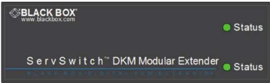
ACXMODH2-R2 front view.
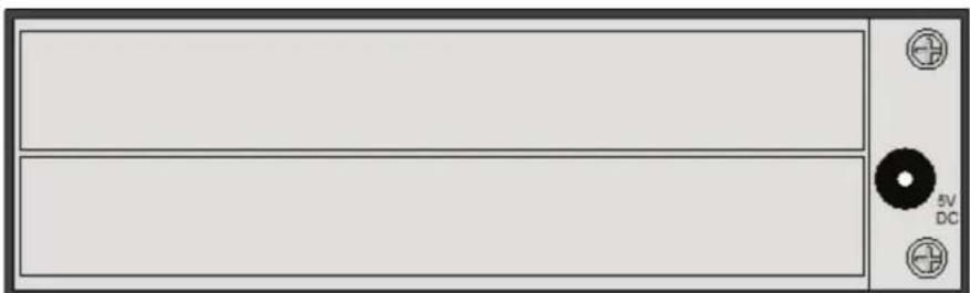
natural_image
Front panel of a computer monitor with indicator lights and a CD, no visible text or symbols on the screen or body.ACXMODH2-R2 back view.
ACXMODH2R-R2 and Compatible Accessories
ACXMODH2R-R2 Specifications
| Connectors (2) | 2.5-mm barrel connectors for power |
| Power Primary | Power Output: 5 V, 3 A;Secondary Power Output (optional): 5 V, 3 A |
| Dimensions | 1.7"H x 5.7"W x 5.75"D (4.3 x 14.5 x 14.6 cm) |
| Weight | 0.6 lb. (0.3 kg) |
ACXMODH2R-R2 Accessories
| Rackmount Option ACXMODHEAR2 | |
| Optional Redundant Power Supply ACXMODH2-PS | |
| Blanking Panel Options ACXMODH21-4S or ACXMOD21-8S | |
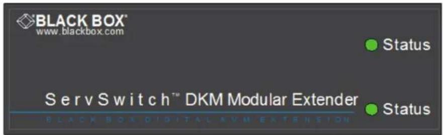
ACXMODH2R-R2 front view.
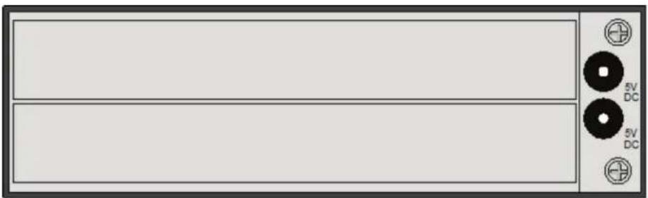
natural_image
Front panel of a computer interface with two 5V DC buttons and a display unit (no text or symbols on the panel itself)ACXMODH2R-R2 back view.
ACXMODH2R-P-R2 and Compatible Accessories
ACXMODH2R-P-R2 Specifications
| Connectors (1) | 2.5-mm barrel connector for power; (1) IEC320, C14 |
| Power Primary | Power Output: 5 V, 3 ANOTE: If you are using this chassis as an 8-Port DKM FX Switch, use a higher amperage power supply such as ACXMODH6-PS or the main IEC320 power input.Secondary Power Output (optional): 5 V, 3 A |
| Dimensions | 1.7"H x 8.75"W x 5.75"D (4.3 x 22.2 x 14.6 cm) |
| Weight | 0.8 lb. (0.4 kg) |
ACXMODH2R-P-R2 Accessories
| Rackmount Option ACXMODHEAR2P | |
| Optional Redundant Power Supply | ACXMODH2-PS (5 V, 3 A, for standard cards);ACXMODH4-PS (5 V, 5 A, for load sharing) |
| Blanking Panel Options ACXMODH21-4S or ACXMOD21-8S | |
ACXMODH2R-P-R2 front view.
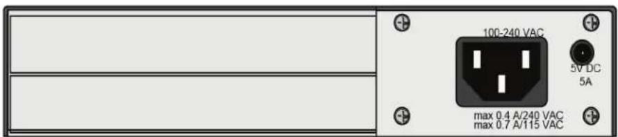
ACXMODH2R-P-R2 back view.
ACXMODH4-R2 and Compatible Accessories
ACXMODH4-R2 Specifications
| Connectors (1) | 2.5-mm barrel connector for power |
| Power Primary | Power Output: 5 V, 5 A;Secondary Power Output: Does not support redundant power |
| Dimensions | 1.7"H x 11.5"W x 5.75"D (4.3 x 29.2 x 14.6 cm) |
| Weight | 0.9 lb. (0.4 kg) |
ACXMODH4-R2 Accessories
| Rackmount Option ACXMODHEAR4 | |
| Optional Redundant Power Supply Does not support redundant power | |
| Blanking Panel Options ACXMODH21-4S or ACXMOD21-8S | |

ACXMODH4-R2 front view.

natural_image
Front view of a rectangular panel with two horizontal sections, one containing a small circular symbol and the other marked with 'TV DC' (no text or labels on panels)ACXMODH4-R2 back view.
ACXMODH4R-R2 and Compatible Accessories
ACXMODH4R-R2 Specifications
| Connectors (2) | 2.5-mm barrel connectors for power |
| Power Primary | Power Output: 5 V, 5 A;Secondary Power Output (optional): 5 V, 5 A |
| Dimensions | 1.7"H x 11.5"W x 5.75"D (4.3 x 29.2 x 14.6 cm) |
| Weight | 0.9 lb. (0.4 kg) |
ACXMODH4R-R2 Accessories
| Rackmount Option ACXMODHEAR4 | |
| Optional Redundant Power Supply ACXMODH4-PS | |
| Blanking Panel Options ACXMODH21-4S or ACXMOD21-8S | |

ACXMODH4R-R2 front view.

ACXMODH4R-R2 back view.
ACXMODH6R-R2 and Compatible Accessories
ACXMODH6R-R2 Specifications
| Connectors (1) | IEC320 main power input; (1) 2.5-mm barrel connector for redundant power |
| Power Primary | Power Output: 5 V, 8 A; Secondary Power Output (optional): 5 V, 8 A |
| Dimensions | 1.7"H x 17.5"W x 5.75"D (4.3 x 44.5 x 14.6 cm) |
| Weight | 1.75 lb. (0.8 kg) |
ACXMODH6R-R2 Accessories
| Rackmount Option ACXMODHEAR6 | |
| Optional Redundant Power Supply ACXMODH6-PS | |
| Blanking Panel Options ACXMODH21-4S or ACXMOD21-8S | |

ACXMODH6R-R2 front view.
ACXMODH6R-R2 back view.
ACXMODH6BPAC-R2 and Compatible Accessories
ACXMODH6BPAC-R2 Specifications
| Connectors (2) | IEC320 main power inputs |
| Power Primary | Power Output: 5 V, 10 A;Redundant Power Output (included): 5 V, 10 A |
| Dimensions | 1.7"H x 17.5"W x 8"D (4.3 x 44.5 x 20.3 cm) |
| Weight | 1.75 lb. (0.8 kg) |
ACXMODH6BPAC-R2 Accessories
| Rackmount Option ACXMODHEAR6FPAC | |
| Redundant Power Supply Included | |
| Blanking Panel Options ACXMODH21-4S or ACXMOD21-8S | |
| Optional Fan ACXMODH6FAN | |

natural_image
Front view of a gray rectangular metal plate with bolt holes (no text or symbols)ACXMODH6BPAC-R2 front view.

natural_image
Front view of a rack-mounted server or network device with multiple ports and connectors (no visible text or labels)ACXMODH6BPAC-R2 back view.
ACXMODH6FPAC-R2 and Compatible Accessories
ACXMODH6FPAC-R2 Specifications
| Connectors (2) | IEC320 main power inputs |
| Power Primary | Power Output: 5 V, 10 A;Secondary Power Output (optional): 5 V, 10 A |
| Dimensions | 1.7"H x 17.5"W x 8"D (4.3 x 44.5 x 20.3 cm) |
| Weight | 1.75 lb. (0.8 kg) |
ACXMODH6FPAC-R2 Accessories
| Rackmount Option ACXMODHEAR6FPAC | |
| Redundant Power Supply Included | |
| Blanking Panel Options ACXMODH21-4S or ACXMOD21-8S | |
| Optional Fan ACXMODH6FAN | |

natural_image
Front view of a gray electronic device panel with two buttons and a plus button (no text or symbols visible)ACXMODH6FPAC-R2 front view.

natural_image
Pure electrical circuit lines without any symbolsACXMODH6FPAC-R2 back view.
ACXMODH21R and Compatible Accessories
ACXMODH21R Specifications
| Connectors (2) | IEC320 main power inputs; (21) 20-position headers for cards |
| Power Primary | Power Output: 5 V, 50 A; Secondary Power Output (optional): 5 V, 50 A |
| Dimensions 7 | "H x 19"W x 18.25"D (17.8 x 48.3 x 46.4 cm) |
| Weight 16 lb. | (7.3 kg) |
ACXMODH21R Accessories
| Rackmount Option Included | |
| Optional Redundant Power Supply ACXMODH21-PS | |
| Blanking Panel Options ACXMODH21-4S or ACXMOD21-8S | |
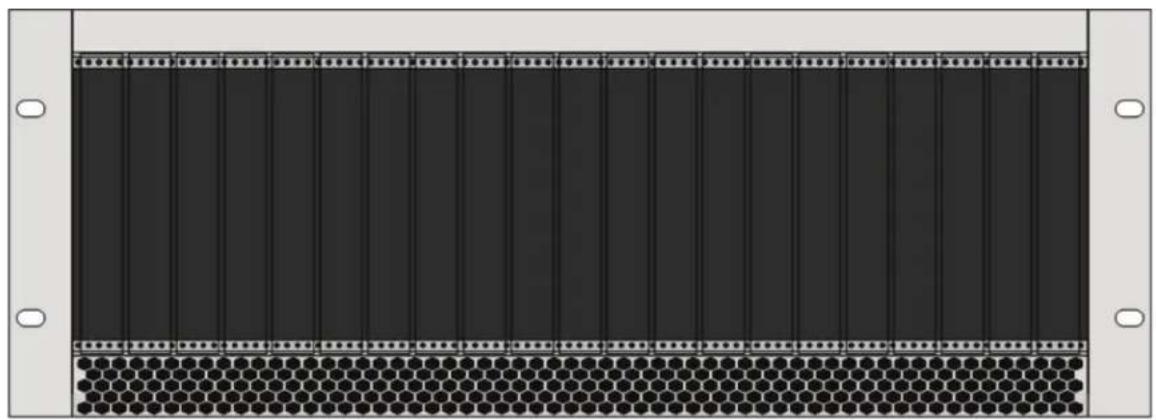
natural_image
Front panel of a server rack with hexagonal grid pattern and mounting holes (no text or symbols)ACXMODH21R front view.
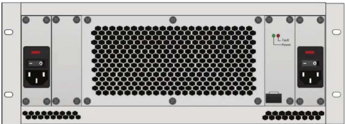
natural_image
Front view of a server rack unit with hexagonal grid and labeled ports (no readable text or symbols)ACXMODH21R back view.
2.6.2 ACX1MT-DHID-C/ACX1MR-DHID-C
CPU Unit, rear view
CON Unit, rear view
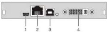
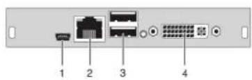
CPU unit CON unit
| 1 Service port 1 | Service port | ||
| 2 | Connect to interconnect cable | 2 | Connect to interconnect cable |
| 3 | To CPU: USB-HID | 3 | Connect to USB-HID devices |
| 4 | To CPU: DVI-D | 4 | Connect to DVI monitor |
2.6.3 ACX1MT-VDHID-C /ACX1MR-VDHID-C
CPU Unit, rear view
CON Unit, rear view
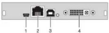
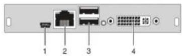
CPU unit CON unit
| 1 Service port 1 Service port | |||
| 2 | Connect to interconnect cable | 2 | Connect to interconnect cable |
| 3 | To CPU: USB-HID | 3 | Connect to USB-HID devices |
| 4 | To CPU: DVI-D, DVI-I | 4 | Connect to DVI monitor, DVI-I |
2.6.4 Basic Module ACX1MT-DHID-SM/ACX1MR-DHID-SM
CPU Unit, rear view
CON Unit, rear view
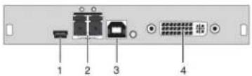
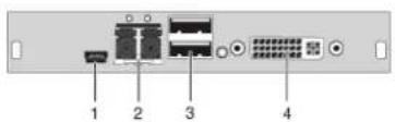
CPU unit CON unit
| 1 Service port 1 Service port | |||
| 2 | Connect to interconnect cable | 2 | Connect to interconnect cable |
| 3 To CPU: USB-HID 3 Connect to USB-HID devices | |||
| 4 To CPU: DVI-D 4 Connect to DVI monitor | |||
2.6.5 ACX1MT-DHS-SM/ACX1MR-DHS-SM
CPU Unit, rear view
CON Unit, rear view
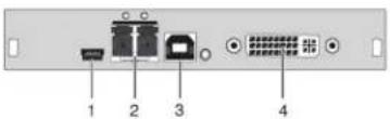
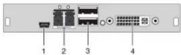
CPU unit CON unit
| 1 Service port 1 Service port | |||
| 2 | Connect to interconnect cable | 2 | Connect to interconnect cable |
| 3 To CPU: USB-HID 3 Connect to USB-HID devices | |||
| 4 To CPU: DVI-D 4 Connect to DVI monitor | |||
2.6.6 ACX1MT-VHID-SM/ACX1MR-VHID-SM
CPU Unit, rear view
CON Unit, rear view
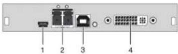
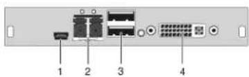
| CPU unit CON unit | |||
| 1 Service port 1 Service port | |||
| 2 | Connect to interconnect cable | 2 | Connect to interconnect cable |
| 3 To CPU: USB-HID 3 Connect to USB-HID devices | |||
| 4 | To CPU: DVI-D, DVI-I | 4 | Connect to DVI monitor, DVI-D |
2.6.7 ACX1MT-DHID-2C/ACX1MR-DHID-2C
CPU Unit
CON Unit
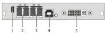
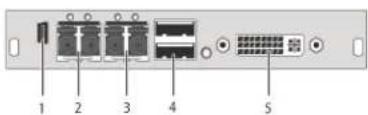
Rear view
1 Service port
2 Connected to interconnect cable 1
3 Connected to interconnect cable 2
4 To CPU: USB-HID
5 To CPU: DVI-D
Rear view
1 Service port
2 Connected to interconnect cable 1
3 Connected to interconnect cable 2
4 Connect to USB-HID devices
5 Connect to DVI monitor
2.6.8 ACX1MT-VDHID-2S/ACX1MR-VDHID-2S
CPU Unit
CON Unit
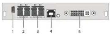
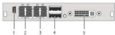
Rear view Rear view
1 Service port 1 Service port
2 Connected to interconnect cable 1 2 Connected to interconnect cable 1
3 Connected to interconnect cable 2 3 Connected to interconnect cable 2
4 To CPU: USB-HID 4 Connect to USB-HID devices
5 To CPU: DVI-D, DVI-I 5 Connect to DVI monitor, DVI-I
2.6.9 ACX1MT-DHID-2S/ACX1MR-DHID-2S
CPU Unit
CON Unit
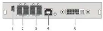
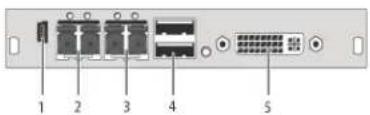
Rear view Rear view
1 Service port 1 Service port
2 Connected to interconnect cable 1 2 Connected to interconnect cable 1
3 Connected to interconnect cable 2 3 Connected to interconnect cable 2
4 To CPU: USB-HID 4 Connect to USB-HID devices
5 To CPU: DVI-D 5 Connect to DVI monitor
2.6.10 ACX1MT-VDHID-2S/ACX1MR-VDHID-2S
CPU Unit
CON Unit
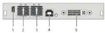
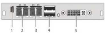
Rear view Rear view
1 Service port 1 Service port
2 Connected to interconnect cable 1 2 Connected to interconnect cable 1
3 Connected to interconnect cable 2 3 Connected to interconnect cable 2
4 To CPU: USB-HID 4 Connect to USB-HID devices
5 To CPU: DVI-D, DVI-I 5 Connect to DVI monitor, DVI-I
2.6.11 Basic Module ACX1MT-DVHID-C/ACX1MR-DVHID-C
CPU Unit, rear view
CON Unit, rear view
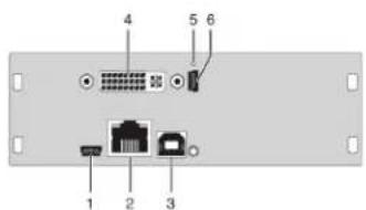
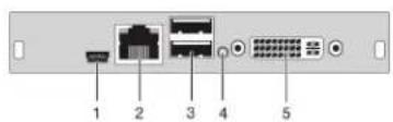
| CPU unit | CON unit | ||
| 1 | Service port | 1 | Service port |
| 2 | Connect to interconnect cable | 2 | Connect to interconnect cable |
| 3 | To CPU: USB-HID | 3 | Connect to USB-HID devices |
| 4 | To CPU: DVI-I (VGA/DVI) | 4 | IR receiver for remote control |
| 5 | IR receiver for remote control | 5 | Connect to DVI monitor, DVI-D |
| 6 | Service port | — | — |
2.6.12 Basic Module ACX1MT-DVHID-SM/ACX1MR-DVHID-SM
CPU Unit, rear view
CON Unit, rear view
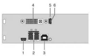
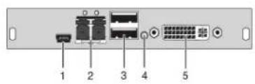
| CPU unit CON unit | |||
| 1 Service port 1 Service port | |||
| 2 | Connect to interconnect cable | 2 | Connect to interconnect cable |
| 3 To CPU: USB-HID 3 Connect to USB-HID devices | |||
| 4 To CPU: DVI-H (VGA/DVI) 4 IR receiver for remote control | |||
| 5 | IR receiver for remote control | 5 | Connect to DVI monitor, DVI-D |
| 6 Service port — — | |||
2.6.13 ACX2MT-DLH-C/ACX2MR-DLH-C
CPU Unit
CON Unit
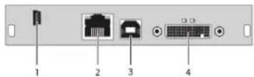
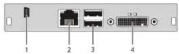
Rear view
1 Service port
2 Connected to interconnect cable
3 To CPU: USB-HID
4 To CPU: DMS-59
Rear view
1 Service port
2 Connected to interconnect cable
3 Connect to USB-HID devices
4 Connect to DVI monitor(s) (DMS-59)
2.6.14 ACX2MT-DHH-C/ACX2MR-DHH-C
CPU Unit
CON Unit
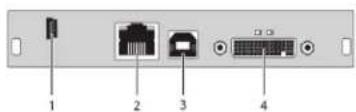
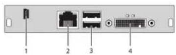
Rear view Rear view
1 Service port 1 Service port
2 Connected to interconnect cable 2 Connected to interconnect cable
3 To CPU: USB-HID 3 Connect to USB-HID devices
4 To CPU: DMS-59 4 Connect to monitor(s) (DMS-59)
2.6.15 ACX2MT-DLH-SM/ACX2MR-DLH-SM
CPU Unit
CON Unit
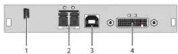
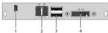
Rear view Rear view
1 Service port 1 Service port
2 Connected to interconnect cable 2 Connected to interconnect cable
3 To CPU: USB-HID 3 Connect to USB-HID devices
4 To CPU: DMS-59 4 Connect to monitor(s) (DMS-59)
2.6.16 ACX2MT-DHH-SM/ACX2MR-DHH-SM
CPU Unit
CON Unit
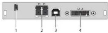
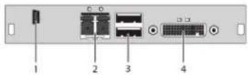
Rear view Rear view
1 Service port 1 Service port
2 Connected to interconnect cable 2 Connected to interconnect cable
3 To CPU: USB-HID 3 Connect to USB-HID devices
4 To CPU: DMS-59 4 Connect to monitor(s) (DMS-59)
2.6.17 ACX2MT-DHHS-SM/ACX2MR-DHHS-SM
CPU Unit
CON Unit
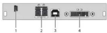
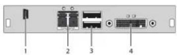
Rear view Rear view
1 Service port 1 Service port
2 Connected to interconnect cable 2 Connected to interconnect cable
3 To CPU: USB-HID 3 Connect to USB-HID devices
4 To CPU: DMS-59 4 Connect to monitor(s) (DMS-59)
2.6.18 ACX2MT-DLHS-SM/ACX2MR-DLHS-SM
CPU Unit
CON Unit
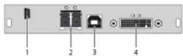
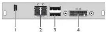
Rear view Rear view
1 Service port 1 Service port
2 Connected to interconnect cable 2 Connected to interconnect cable
3 To CPU: USB-HID 3 Connect to USB-HID devices
4 To CPU: DMS-59 4 Connect to monitor(s) (DMS-59)
2.6.19 ACX2MT-DLH-2C/ACX2MR-DLH-2C
CPU Unit
CON Unit
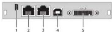
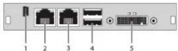
Rear view Rear view
1 Service port 1 Service port
2 Connected to interconnect cable 1 2 Connected to interconnect cable 1
3 Connected to interconnect cable 2 3 Connected to interconnect cable 2
4 To CPU: USB-HID 4 Connect to USB-HID devices
5 To CPU: DMS-59 5 Connect to monitor(s) (DMS-59)
2.6.20 ACX2MT-DHH-2C/ACX2MT-DHH-2C
CPU Unit
CON Unit
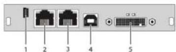
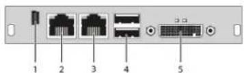
Rear view Rear view
1 Service port 1 Service port
2 Connected to interconnect cable 1 2 Connected to interconnect cable 1
3 Connected to interconnect cable 2 3 Connected to interconnect cable 2
4 To CPU: USB-HID 4 Connect to USB-HID devices
5 To CPU: DMS-59 5 Connect to monitor(s) (DMS-59)
2.6.21 ACX2MT-DLH-SM/ACX2MT-DLH-SM
CPU Unit
CON Unit
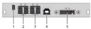
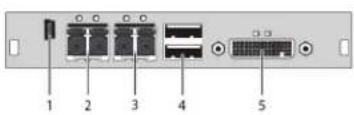
Rear view Rear view
1 Service port 1 Service port
2 Connected to interconnect cable 1 2 Connected to interconnect cable 1
3 Connected to interconnect cable 2 3 Connected to interconnect cable 2
4 To CPU: USB-HID 4 Connect to USB-HID devices
5 To CPU: DMS-59 5 Connect to monitor(s) (DMS-59)
2.6.22 ACX1MT-HDMI-C/ACXMR-HDMI-C
CPU Unit
CON Unit
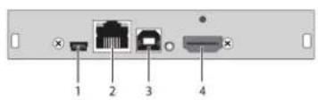
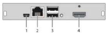
Rear view Rear view
1 Service port 1 Service port
2 Connected to interconnect cable
2 Connected to interconnect cable
3 To CPU: USB-HID 3 Connect to USB-HID devices
4 To CPU: HDMI 4 Connect to HDMI monitor
2.6.23 ACX1MT-HDMI-2C/ACX1MR-HDMI-2C
CPU Unit
CON Unit
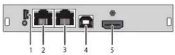
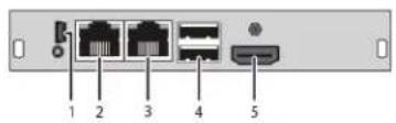
Rear view Rear view
1 Service port 1 Service port
2 Connected to interconnect cable 1 2 Connected to interconnect cable 1
3 Connected to interconnect cable 2 3 Connected to interconnect cable 2
4 To CPU: USB-HID 4 Connect to USB-HID devices
5 To CPU: HDMI 5 Connect to HDMI monitor
2.6.24 ACX1MT-HDM2-C
CPU Unit
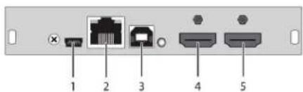
Rear view
1 Service port
2 Connected to interconnect cable
3 To CPU: USB-HID
4 To CPU: HDMI
5 Local output: HDMI
2.6.25 ACX1MT-HDM2-2C
CPU Unit
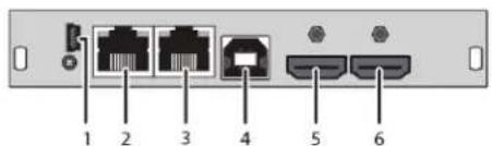
Rear view
1 Service port
2 Connected to interconnect cable 1
3 Connected to interconnect cable 2
3 To CPU: USB-HID
4 To CPU: HDMI
5 Local output: HDMI
2.6.26 ACX1MT-HDMI-SM/ACX1MR-HDMI-SM
CPU Unit
CON Unit
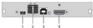
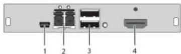
Rear view Rear view
1 Service port 1 Service port
2 Connected to interconnect cable 1 2 Connected to interconnect cable 1
3 To CPU: USB-HID 3 Connect to USB-HID devices
4 To CPU: HDMI 4 Connect to HDMI monitor
2.6.27 ACX1MT-HDMI-SM/ACX1MR-HDMI-SM
CPU Unit
CON Unit
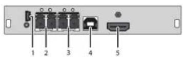
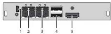
Rear view Rear view
1 Service port 1 Service port
2 Connected to interconnect cable 1 2 Connected to interconnect cable 1
3 Connected to interconnect cable 2 3 Connected to interconnect cable 2
4 To CPU: USB-HID 4 Connect to USB-HID devices
5 To CPU: HDMI 5 Connect to HDMI monitor
2.6.28 ACX1MT-HDM2-SM/ACX1MR-HDM2-SM
CPU Unit
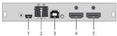
Rear view
1 Service port
2 Connected to interconnect cable
3 To CPU: USB-HID
4 To CPU: HDMI
5 Local output: HDMI
2.6.29 ACX1MT-HDM2-2S
CPU Unit
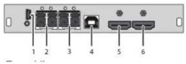
Rear view
1 Service port
2 Connect to interconnect cable
3 Connect to interconnect cable
4 To CPU: USB-HID
5 To CPU: HDMI
6 Local output: HDMI
2.6.30 ACX1MR-HDSW-C
CON Unit
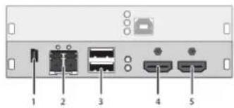
Rear view
1 Service port
2 Connect to interconnect cable
3 Connect to USB-HID devices
4 Connect to HDMI monitor
5 Local input: HDMI
2.6.31 ACX1MR-HDSW-2C
CON Unit
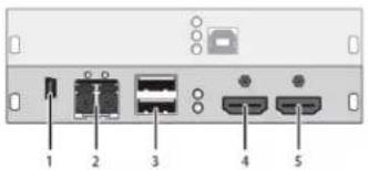
Rear view
1 Service port
2 Connect to interconnect cable 1
3 Connect to USB-HID devices
4 Connect to HDMI monitor
5 Local input: HDMI
2.6.32 ACX1MR-HDSW-SM
CON Unit
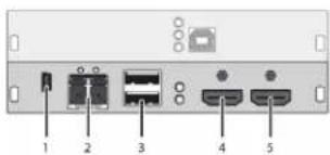
Rear view
1 Service port
2 Connect to interconnect cable 1
3 Connect to USB-HID devices
4 Connect to HDMI monitor
5 Local input: HDMI
2.6.33 ACX1MR-HDSW-2S
CON Unit
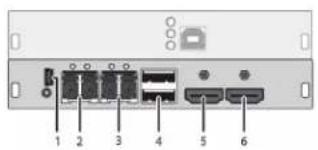
Rear view
1 Service port
2 Connect to interconnect cable 1
3 Connect to interconnect cable 2
4 Connect to USB-HID devices
5 Connect to HDMI monitor
6 Local input: HDMI
2.6.34 ACX1MT-HDO-C /ACX1MR-HDO-C
CPU Unit
CON Unit
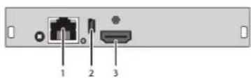
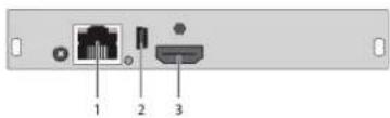
Rear view Rear view
1 Connected to interconnect cable 1 Connected to interconnect cable
2 Service port 2 Service port
3 To CPU: HDMI 3 Connect to HDMI monitor
2.6.35 ACX1MT-HDO-SM/ACX1MR-HDO-SM
CPU Unit
CON Unit

Rear view Rear view
1 Connected to interconnect cable 1 Connected to interconnect cable
2 Service port 2 Service port
3 To CPU: HDMI 3 Connect to HDMI monitor
NOTE: The video-only modules without USB-HID connection are only meant for use with basic extender modules.
2.6.36 ACX2MT-DPH-C/ACX2MR-DPH-C
CPU Unit
CON Unit

Rear view Rear view
1 Service port 1 Service port
2 Connect to interconnect cable 2 Connect to interconnect cable
3 To CPU: USB-HID
3 Connect to USB-HID devices
4 To CPU: DisplayPort
4 Connect to DisplayPort monitor
2.6.37 ACX2MT-DPH-SM/ACX2MR-DPH-SM
CPU Unit
CON Unit
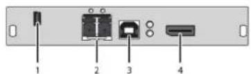
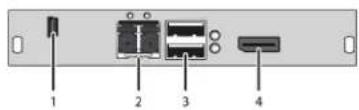
Rear view Rear view
1 Service port 1 Service port
2 Connect to interconnect cable 2 Connect to interconnect cable
3 To CPU: USB-HID 3 Connect to USB-HID devices
4 To CPU: DisplayPort 4 Connect to DisplayPort monitor
2.6.38 ACX2MT-DPHS-SM/ACX2MR-DPHS-SM
CPU Unit
CON Unit
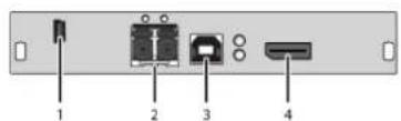
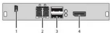
Rear view Rear view
1 Service port 1 Service port
2 Connect to interconnect cable 2 Connect to interconnect cable
3 To CPU: USB-HID 3 Connect to USB-HID devices
4 To CPU: DisplayPort 4 Connect to DisplayPort monitor
2.6.39 ACX2MT-DPH-2C/ACX2MR-DPH-2C
CPU Unit
CON Unit
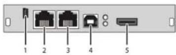
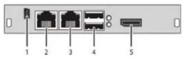
Rear view Rear view
1 Service port 1 Service port
2 Connect to interconnect cable 1 2 Connect to interconnect cable 1
3 Connect to interconnect cable 2 3 Connect to interconnect cable 2
4 To CPU: USB-HID 4 Connect to USB-HID devices
5 To CPU: DisplayPort 5 Connect to DisplayPort monitor
2.6.40 ACX2MT-DPH-2S/ACX2MR-DPH-2S
CPU Unit
CON Unit
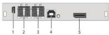
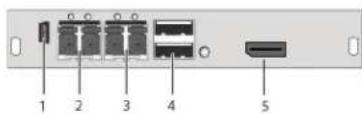
Rear view Rear view
1 Service port 1 Service port
2 Connect to interconnect cable 1 2 Connect to interconnect cable 1
3 Connect to interconnect cable 2 3 Connect to interconnect cable 2
4 To CPU: USB-HID 4 Connect to USB-HID devices
5 To CPU: DisplayPort 5 Connect to DisplayPort monitor
2.6.41 ACX2MT-DPHS-2S/ACX2MR-DPHS-2S
CPU Unit
CON Unit
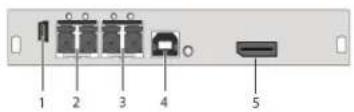
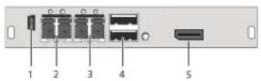
Rear view Rear view
1 Service port 1 Service port
2 Connect to interconnect cable 1 2 Connect to interconnect cable 1
3 Connect to interconnect cable 2 3 Connect to interconnect cable 2
4 To CPU: USB-HID 4 Connect to USB-HID devices
5 To CPU: DisplayPort 5 Connect to DisplayPort monitor
2.6.42 Upgrade Module ACX1MT-HID/ACX1MR-HID
CPU Unit, rear view
CON Unit, rear view
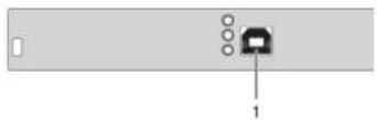
natural_image
Back panel with a connector labeled '1' pointing to a rectangular slot (no text or symbols beyond the label)| CPU unit | CON unit | ||
| 1 | To CPU: USB-HID | 1 | Connect to USB-HID devices |
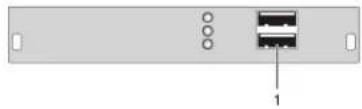
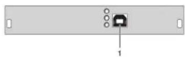
2.6.43 ACX1MT-EU/ACX1MR-EU
CPU Unit
CON Unit
natural_image
Back panel with a small black square component and four circular holes, labeled '1' at the bottom (no text or symbols on the component itself)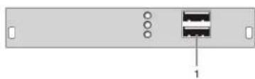
natural_image
Back panel of a network device showing two ports and a connector (no text or symbols visible)Rear view Rear view
1 To CPU: USB-HID 1 Connect to USB-HID devices
2.44 Upgrade Module ACX1MT-AR/ACX1MR-AR
CPU Unit, rear view
CON Unit, rear view
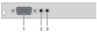
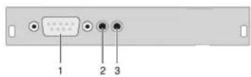
| CPU unit CON unit | ||
| 1 Connect to serial (DB9) 1 Connect to serial DB9 | ||
| 2 Audio IN 2 Audio IN | ||
| 3 Audio OUT 3 Audio OUT | ||
2.6.45 ACX1MT-ARP/ACX1MR-ARP
CPU Unit
CON Unit
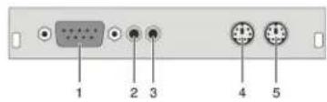
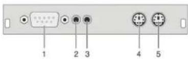
Rear view
1 Connect to serial DB9
2 Audio IN
3 Audio OUT
4 To CPU: PS/2 mouse
5 To CPU: PS/2 keyboard
Rear view
1 Connect to serial DB9
2 Audio IN
3 Audio OUT
4 Connect to PS/2 module
5 Connect to PS/2 keyboard
2.6.46 Upgrade Module ACX1MT-DA/ACX1MR-DA
CPU Unit, rear view
CON Unit, rear view
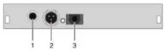
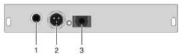
CPU unit CON unit
| 1 S/PDIF input (RCA) 1 S/PDIF output (RCA) |
| 2 AES/EBU input (Mini-XLR) 2 AES/EBU output (Mini-XLR) |
| 3 S/PDIF input (TOSLINK *) 3 S/PDIF output (TOSLINK) |
2.6.47 Upgrade Module ACX1MT-ARH/ACX1MR-ARH
CPU Unit, rear view
CON Unit, rear view
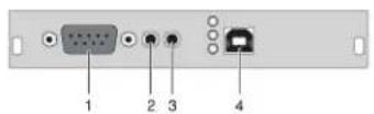
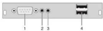
CPU unit CON unit
| 1 Connect to serial (DB9) 1 Connect to serial (DB9) | |||
| 2 Audio IN 2 Audio IN | |||
| 3 Audio OUT | 3 Audio OUT | ||
| 4 | To CPU: USB-HID | 4 | Connect to USB-HID devices |
2.6.48 Upgrade Module ACX1MT-DAH/ACX1MR-DAH
CPU Unit, rear view
CON Unit, rear view
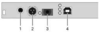
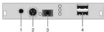
CPU unit CON unit
| 1 S/PDIF input (RCA) 1 S/PDIF output (RCA) | |
| 2 AES/EBU input (Mini-XLR) 2 AES/EBU output (Mini-XLR) | |
| 3 S/PDIF input (TOSLINK) 3 S/PDIF output (TOSLINK) | |
| 4 To CPU: USB-HID 4 Connect to USB-HID devices |
2.6.49 ACX1MT-ARE/ACX1MR-ARE
CPU Unit CON Unit
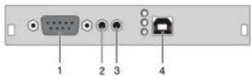
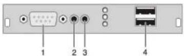
Rear view
1 Connect to serial DB9
2 Audio IN
3 Audio OUT
4 To CPU: USB 2.0
Rear view
1 Connect to serial DB9
2 Audio IN
3 Audio OUT
4 Connect to USB 2.0 devices
2.6.50 ACX1MT-DAE/ACX1MR-DAE
CPU Unit CON Unit

Figure 2-X.
Rear view Rear view
1 S/PDIF input (RCA) 1 S/PDIF output (RCA)
2 AES/EBU input (Mini-XLR) 2 AES/EBU output (Mini-XLR)
3 S/PDIF input (TOSLINK) 3 S/PDIF output (TOSLINK)
4 To CPU: USB 2.0 4 Connect to USB 2.0 devices
2.6.51 Upgrade Module ACX1MT-DAX/ACX1MR-DAX
CPU Unit, rear view CON Unit, rear view
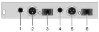
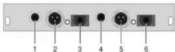
| CPU unit | CON unit | ||
| 1 | S/PDIF input (RCA) | 1 | S/PDIF output (RCA) |
| 2 | AES/EBU input (Mini-XLR) | 2 | AES/EBU output (Mini-XLR) |
| 3 | S/PDIF input (TOSLINK) | 3 | S/PDIF output (TOSLINK) |
| 4 | S/PDIF output (RCA) | 4 | S/PDIF input (RCA) |
| 5 | AEX/EBU output (Mini-XLR) | 5 | AES/EBU input (Mini-XLR) |
| 6 | S/PDIF output (TOSLINK) | 6 | S/PDIF input (TOSLINK) |
2.6.52 Upgrade Module ACX1MT-ARD/ACX1MR-ARD
CPU Unit, rear view
CON Unit, rear view
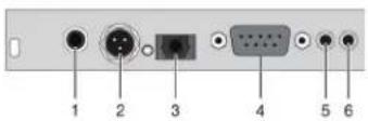
CPU unit CON unit
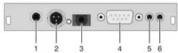
| 1 S/PDIF input (RCA) 1 S/PDIF output (RCA) | |
| 2 AES/EBU input (Mini-XLR) 2 AES/EBU output (Mini-XLR) | |
| 3 S/PDIF input (TOSLINK) 3 S/PDIF output (TOSLINK) | |
| 4 Connect to serial (DB9) 4 Connect to serial (DB9) | |
| 5 Audio IN 5 Audio IN | |
| 6 Audio OUT 6 Audio OUT |
2.6.53 USB 2.0 Module ACX1MT-U2-C/ACX1MR-U2-C
CPU Unit, rear view
CON Unit, rear view
CPU unit CON unit
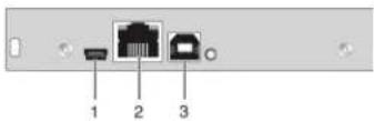
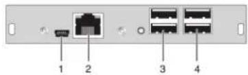
| 1 Service port | 1 Service port | ||
| 2 | Connect to interconnect cable | 2 | Connect to interconnect cable |
| 3 | To CPU: USB 2.0 | 3 | Connect to USB 2.0 devices |
NOTE: Operates at 480 Mbps.
2.6.54 USB 2.0 Module ACX1MT-U2-SM/ACX1MR-U2-SM
CPU Module, rear view CON Module, rear view
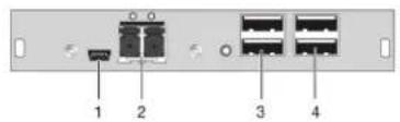
| CPU unit CON unit | |||
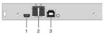
| 1 Service port 1 | Service port | ||
| 2 | Connect to interconnect cable | 2 | Connect to interconnect cable |
| 3 To CPU: USB | 2.0 3 Connect to USB 2.0 devices | ||
NOTE: Operates at 480 Mbps.
2.6.55 USB 2.0 Module ACX1MT-U23-C/ACX1MR-U23-C
CPU Unit, rear view CON Unit, rear view
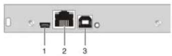
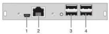
| CPU unit CON unit | |||
| 1 Service port 1 | Service port | ||
| 2 | Connect to interconnect cable | 2 | Connect to interconnect cable |
| 3 To CPU: USB | 2.0 3 Connect to USB 2.0 devices | ||
2.6.56 USB 2.0 Module ACX1MT-U23-SM/ACX1MR-U23-SM
CPU Module, rear view CON Module, rear view
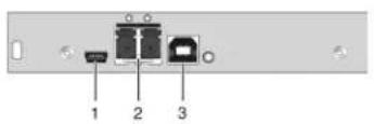
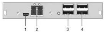
| CPU unit CON unit | |||
| 1 Service port 1 | Service port | ||
| 2 | Connect to interconnect cable | 2 | Connect to interconnect cable |
| 3 To CPU: USB | 2.0 3 Connect to USB 2.0 devices | ||
2.6.57 ACX2MT-DPH4KHS-SM/ACX2MR-DPH4KHS-SM
CPU Unit, rear view
CON Unit, rear view
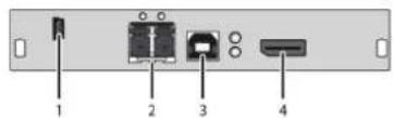
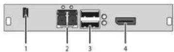
Rear view
Rear view
1 Service port
2 Connect to interconnect cable
3 To CPU: USB-HID
4 To CPU: DisplayPort
1 Service port
2 Connect to interconnect cable
3 Connect to USB-HID devices
4 Connect to DisplayPort monitor
2.6.58 ACX2MT-DPH-2S/ACX2MR-DPH-2S
CPU Unit, rear view
CON Unit, rear view
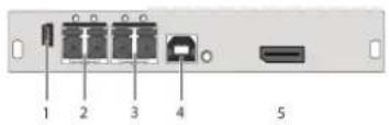
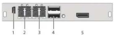
Rear view Rear view
1 Service port 1 Service port
2 Connect to interconnect cable 1 2 Connect to interconnect cable 1
3 Connect to interconnect cable 2 3 Connect to interconnect cable 2
4 To CPU: USB-HID 4 Connect to USB-HID devices
5 To CPU: DisplayPort 5 Connect to DisplayPort monitor
2.7 Status LEDs
2.7.1 KVM Extender Module Status
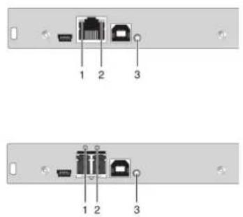
The KVM Extender module has a multicolor LED on both sides to indicate overall status. It also has two additional LEDs on the back side to indicate the connection status.
CPU module, rear view CON module, rear view
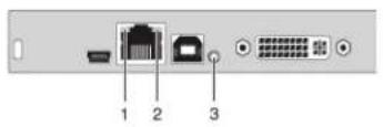
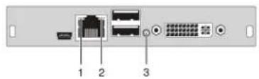
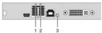
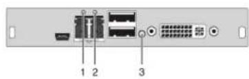
Status LEDs on the basic module.
LED 1 and 2: Connection Status.
| Position | LED | Status | Description |
| 1 | Failure LED (green) | Off | Connection available |
| On or Flashing | Connection failure (flashing for about 20 seconds following a connection failure) | ||
| 2 | Status LED (green) | Flashing | No connection via interconnect cable |
| On | Connection available |
LED 3: USB and Video Status.
| Color Description |
| Red Device ready |
| Violet Connection and USB signal (interconnect) available |
| Green Connection and video signal available |
| Light Blue Connection, USB, and video signal available (operating status) |
2.7.2 KVM Extender Module VGA/DVI-I Status
The KVM Extender module with VGA/DVI-I input has a multicolor LED on the front side of the CPU module to indicate connection status. More information is available via on-screen display (OSD) (see the manual for the Media/DVI Converter [ACS 411A-R2]).
CPU module
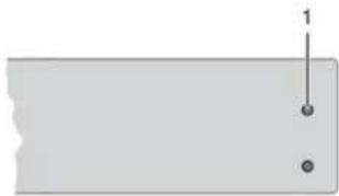
natural_image
Simple diagram with a horizontal line and two dots, no text or symbols presentFront view of the CPU module.
LED 3: Connection Status VGA/DVI-I.
| LED Description |
| Dark Red No video signal; monitor not detected |
| Red Video signal not supported; monitor not detected |
| Green Video signal supported; monitor not detected |
| Blue No video signal; monitor detected |
| Violet Video signal not supported; monitor detected |
| Light Blue Video signal supported; monitor detected |
2.7.3 Upgrade Module Digital Audio Status
The upgrade module digital audio has another multicolor LED on the rear side to indicate the connection status:
CPU module, rear view CON module, rear view
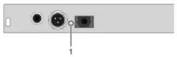
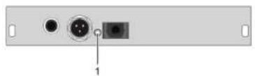
natural_image
Back panel of a computer interface showing two ports with a central connector and a labeled pin (no text or symbols beyond the label)Status upgrade module digital audio.
LED 1: Digital Audio Status.
| LED color Description | |
| Red No signal | |
| Light Blue | Static: CPU Unit: S/PDIF signal (RCA) availablFlashing: CPU Unit: Digital noise |
| Violet | Static: CPU Unit: AES/EBU signal (Mini-XLR) availableFlashing: CPU Unit: Digital noise |
| Blue | Static: CPU Unit: S/PDIF signal (TOSLINK) availableFlashing: CPU Unit: Digital noise |
| Green CON Unit: Signal available | |
2.7.4 Upgrade Module USB-HID Status
The upgrade module USB-HID has three LEDs on the rear side to indicate the connection status:
CPU module, rear view CON module, rear view
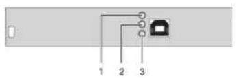
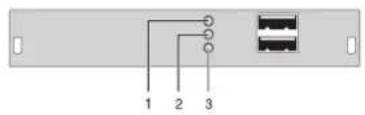
Status upgrade modules USB-HID.
LED 1, 2, and 3: Status.
| Position LED Status Description | |||
| 1, 2 Device LED (orange) | Off No USB-HID device or not supported; USB device connected | ||
| Flashing fast USB-HID device active | |||
| On USB-HID device ready or DKM Modular Extender in command mode | |||
| 3 | Status LED (orange) | Off | No power supply voltageCPU Unit: DKM Modular Extender in command mode or no connectionCON Unit: Keyboard in command mode |
| Flashing slowly | CON Unit: DKM Modular Extender in command mode or no connection | ||
| Flashing fast Operating status | |||
2.7.5 Upgrade Module USB 2.0 Embedded Status
The upgrade module USB 2.0 embedded is fitted with three LEDs on the rear side that indicate the connection status.
CPU module, rear view CON module, rear view
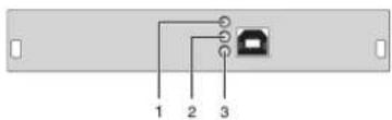
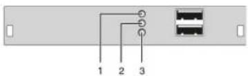
USB 2.0 embedded upgrade module.
USB 2.0 embedded upgrade module status LEDs.
| Position LED Status Description | ||
| 1 Status LED (green) | Off No USB 2.0 device connected | |
| Flashing slowly USB 2.0 device connected | ||
| 2 Status LED (green) | Off No connection to source (computer, CPU) available | |
| Flashing slowly | • Connection to source (computer, CPU) available• No USB 2.0 device connected | |
| 3 Status LED (green) | On | • Connection to source (computer, CPU) available• USB 2.0 device(s) connected |
| Off No connection between CON and CPU module | ||
| On Connection between CON and CPU module available | ||
2.7.6 USB 2.0 Module Status
The USB 2.0 module has a multicolor LED on both sides to indicate overall status. It also has two more LEDs on the back side to indicate the connection status.
CPU module, rear view CON module, rear view
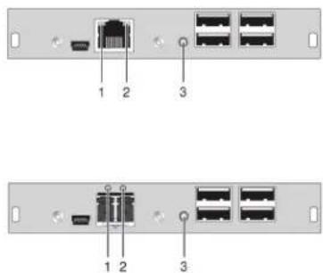
Status USB 2.0 module.
LEDs 1 and 2: Status.
| Position LED Status Description | ||
| 1 Failure LED (green) | Off Connection available | |
| On or flashing | Connection failure (flashing for about 20 seconds following a connection failure) | |
| 2 Status LED (green) | Off No connection via interconnect cable | |
| On Connection available | ||
LED 3: USB 2.0 Status.
| LED color Description | |
| Red | Device ready |
| Green | Only connection available, no USB 2.0 signal |
| Green/light blue flashing | Connection available, no USB 2.0 device connected (only CON unit) |
| Light blue | Connection and USB 2.0 signal available (operating status) |
3. Installation
3.1 Package Contents
Your extender package contains the following items. If anything is missing or damaged, please contact Black Box Technical Support at 724-746-5500 or info@blackbox.com.
KVM Extender:
- DKM Modular Chassis with pre-installed CON/CPU Modules
• (2) 5-VDC international power supply units
• (2) country-specific power cords - Quick Start Guide
• (1) DVI video cable (6-ft. [1.8 m], DVI-D male-to-male)

Figure 3-1. DVI video cable.
• (1) USB cable (6-ft. [1.8 m], Type A to Type B)

Figure 3-2. USB cable.
The KVM Extender VGA/DVI-I (replaces DVI-D cable) also includes:
• VGA cable (6-ft. [1.8 m], VGA male to DVI-I male)

Figure 3-3. VGA cable.
• Infrared remote control
The upgrade module Analog Audio/Serial RS-232 also includes:
- Serial cable (6-ft. [1.8 m], RS-232 male connector)

Figure 3-4. Serial cable.
- Stereo jack cable (5.2-ft. [1.6-m], 3.5 mm male connector)

Figure 3-5. Stereo jack cable.
The upgrade module serial RS-422 also includes:
- Serial cable (6-ft. [1.8-m], RS-422 male connector

Figure 3-6. Serial cable.
The upgrade module Digital Audio also includes:
• RCA cable (8.2-ft. [2.5 m], Cinch male connector)

Figure 3-6. RCA cable.
• TOSLINK cable (6-ft. [1.8 m], F05 male connector)

Figure 3-7. TOSLINK cable.
The upgrade module USB-HID also includes:
- USB cable (6-ft. [1.8 m], USB Type A to Type B)

Figure 3-8. USB cable.
The upgrade module PS/2 also includes:
• (2) PS/2 cables (6-ft. [1.8 m], 6-pole connector)

Figure 3-9. PS/2 cable.
The USB 2.0 embedded upgrade module also includes:
- USB cable (6-ft. [1.8 m], USB Type A to Type B)

Figure 3-10. USB cable.
The USB 2.0 module also includes:
- USB cable (6-ft. [1.8 m], USB Type A to Type B)

Figure 3-11. USB cable.
NOTE: If anything is missing, please contact Black Box Technical Support at 724-746-5500 or info@blackbox.com.
3.2 System Setup
NOTE: If you are a first-time user, we recommend that you set up the system with the CPU module and the CON module in the same room as a test setup. This will enable you to identify and solve any cabling problems, and experiment with your system more conveniently.
NOTE: Verify that interconnect cables, interfaces, and handling of the devices comply with the requirements (see Section 3.1).
3.2.1 KVM Extender Module Setup
- Switch off all devices.
CON Module Installation
-
Connect your monitor(s), keyboard, and mouse to the CON module.
-
Connect the CON module with the interconnect cable(s).
-
Connect the 5-VDC power supply to the CON module.
CPU Module Installation
-
Connect the source (computer, CPU) with the supplied cables to the CPU module. Make sure the cables are not strained.
-
Connect the CPU module to the interconnect cable(s).
-
Connect the 5-VDC power supply to the CPU module.
-
Power up the system.
NOTE: To power up the system, the following sequence is recommended: Monitor – CON module – CPU module – source.
NOTE: The basic module with VGA / DVI-I input is connected as mentioned above. Default output video setting is scaled to 1024 x 768. For a complete and detailed description of the setup and configuration of the VGA option, see the Media/DVI Converter (ACS411A-R2) manual.
NOTE: In the modular chassis, CON modules may be fitted next to CPU modules. The CON/CPU naming convention is based on the module rather than on the chassis that holds the modules.
3.2.2 Setup of Upgrade Modules
You can hot-plug the modules.
Upgrade Module Analog Audio/Serial:
- Connect the audio source with the CPU module (for example, CPU audio output with audio input, CPU audio input with audio output).
- Connect the audio output at the CON module with headphones or suitable speakers.
- Connect the audio input at the CON module with a suitable microphone.
Upgrade Module Serial RS422:
- Connect the CPU to the CPU Unit by using the serial cable.
- Connect the CON Unit to the serial connector of the input device.
Upgrade Module Digital Audio:
- Connect the digital audio source with the suitable audio input of the CPU module.
- Connect the audio output of the CON module with suitable speakers or audio amplifiers.
NOTE: If several active sources are connected, Mini-XLR input takes priority. The audio signal is available at all outputs.
Upgrade Module USB-HID:
- Connect the CPU with the CPU module (USB-HID 2).
- Connect the USB-HID devices with the CON module (Connect to USB-HID device 2).
Upgrade Module PS/2:
- Connect the CPU to a CPU unit with cables for PS/2 devices.
- Connect the PS/2 devices to the CON unit (Connector to PS/2 devices).
Upgrade Module USB 2.0 Embedded:
- Connect the CPU to the CPU Unit (USB 2.0).
- Connect the USB 2.0 devices to the CON Unit (Connect to USB 2.0 devices).
Upgrade Module USB 2.0:
- Connect the CPU to the CPU Unit (USB 2.0).
- Connect the USB 2.0 devices to the CON Unit (Connect to USB 2.0 devices).
3.3 Example Applications
This section illustrates typical installations of DKM Modular Extenders:
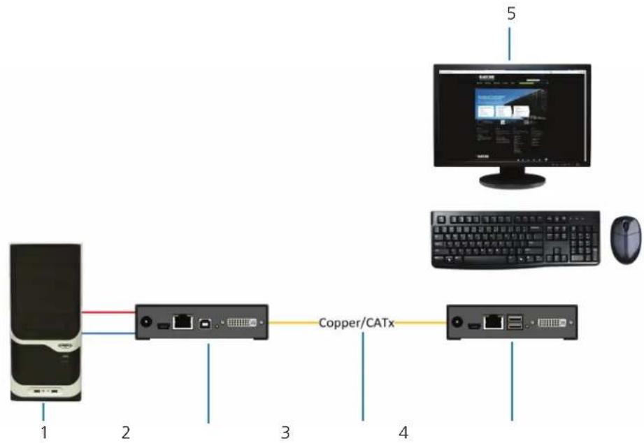
flowchart
graph LR
    A["CPU"] -->|1| B["Switch"]
    B -->|2| C["Copper/CATx"]
    C -->|3| D["Computer"]
    C -->|4| E["Mouse"]
Figure 3-12. DKM Modular Extender (Single-Head).
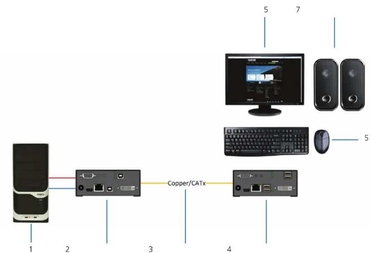
flowchart
graph LR
    A["CPU"] -->|1| B["Switch"]
    B -->|2| C["Copper/CATx"]
    C -->|3| D["Computer"]
    D -->|4| E["Switch"]
    E -->|5| F["Television"]
    D -->|5| G["Mouse"]
    D -->|7| H["Desktop"]
Figure 3-13. DKM Modular Extender (Single-Head with Digital/Analog Audio).
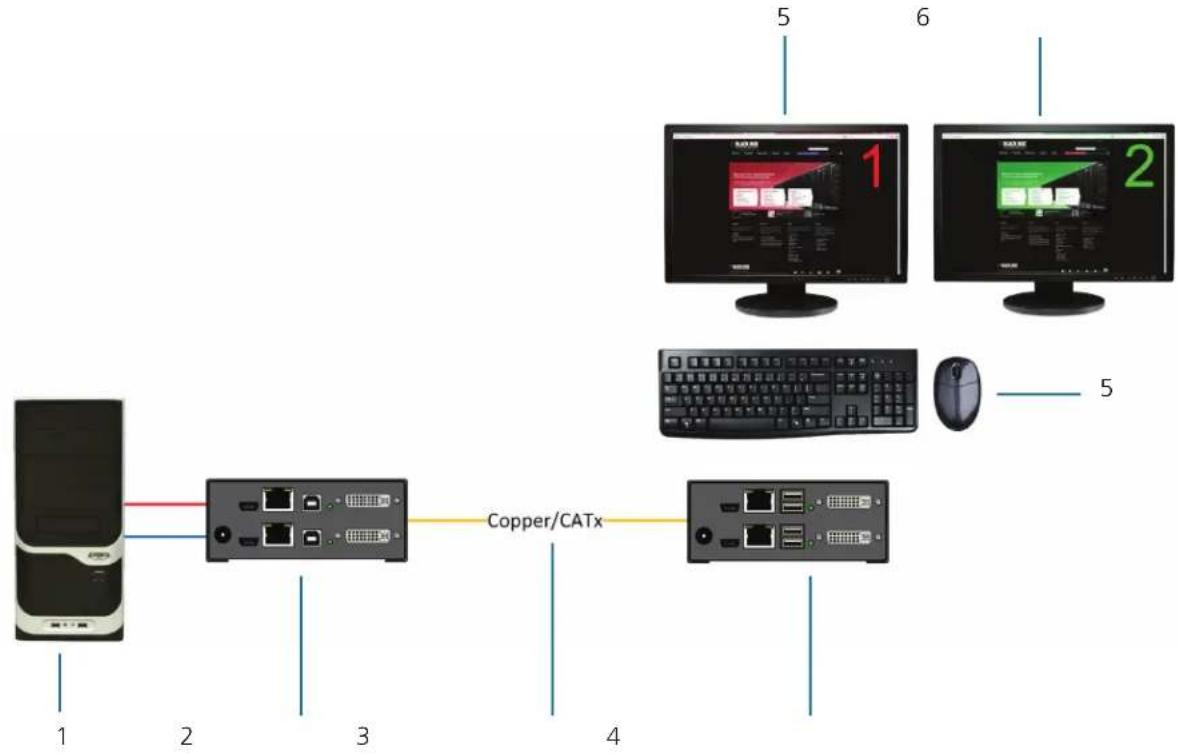
flowchart
graph LR
    Server["Server"] -->|1| CPU1["Computer"]
    CPU1 -->|2| CPU2["CPU"]
    CPU2 -->|3| CopperCathX["Copper/CATx"]
    CopperCathX -->|4| Computer1["Computer"]
    CopperCathX -->|5| PC1["PC"]
    CopperCathX -->|6| PC2["PC"]
Figure 3-14. DKM Modular Extender (Dual-Head).
Table 3-1. Components in Figures 3-10 through 3-12.
| Number Description | |
| 1 Source (computer, CPU) | |
| 2 DKM Modular Extender CPU Unit | |
| 3 Interconnect cable | |
| 4 DKM Modular Extender CON Unit | |
| 5 Console (keyboard, monitor, mouse) | |
| 6 Second monitor (option, only with dual-head devices) | |
| 7 | Audio sink (optional, only with devices with analog audio/serial option or digital audio option |
4. Configuration
4.1 Transmission Parameters
The device operates with a proprietary compression method. In its default configuration, the device adapts dynamically to monitor resolution and image content. This configuration works in almost all conditions. Modify it only if image quality is not fully satisfactory.
NOTE: In exceptional cases, detached "frame droppings" (loss of single pictures) or color effects can appear.
4.2 DDC Settings
By default, the device sends the factory preset DDC information to the CPU. This information works in most cases.
During normal operation, you can download the console monitor's DDC information (see Chapter 5).
For special requirements, DDC information can be retrieved and uploaded as a binary file at both the CPU module and the CON module.
Connect your computer with a USB Mini cable to the CPU module's or CON module's service port.
You can now access the data area of the unit as a flash drive "Extender."
Uploading DDC Information
Copy the binary file containing your specific DDC information to the flash drive of the CPU module or CON module.
The current DDC information is replaced.
Retrieving DDC Information
Copy the file "DDC-EDID.bin" on the flash drive of the CPU module to your computer.
To open the binary file, you have to install a suitable software, for example, WinDDCwrite (Download), on your computer.
Reset to Factory DDC Information
Delete the file called "DDC-EDID.bin" on the flash drive of the CPU module. By deleting this file, the factory DDC Information is restored.
4.3 Command Mode
During normal use, the console keyboard functions in the usual manner. However, for all KVM Extenders with USB-HID support, you can set the keyboard into a Command Mode by using a specific "hotkey" sequence. While in Command Mode, several functions are performed via keyboard commands. To exit Command Mode, press
NOTE: In Command Mode, normal keyboard and mouse operation will cease. Only selected keyboard commands are available.
Table 4-1 lists the keyboard commands to enter and to exit Command Mode and to change the hotkey sequence.
Table 4-1. Keyboard commands.
| Function Keyboard Command | |
| Enter Command Mode 2x/Hotkey | |
| Exit Command Mode | |
| Change Hotkey sequence | ,,,, |
Table 4-2. Keyboard sequences.
| Keyboard Sequence Description |
| +Press keys simultaneously |
| ,Press keys successively |
| 2xPress key quickly, twice in a row (similar to a mouse-click) |
You can change the hotkey sequence to enter Command Mode. Table 4-3 lists the hotkey codes for the available key sequences.
Table 4-3. Hotkey Sequences.
| Hotkey Code Hotkey |
| 0 Freely selectable (since 1-12-2012) |
| 2 2x |
| 3 2x |
| 4 2x |
| 5 2x |
| 6 2x |
| 7 2x |
| 8 2x |
Set freely selectable "Hot Key" (exemplary)
In order to set a freely selectable 'Hot Key' (e.g. 2x
<current "Hot Key">, <c>, <0>, <Space>, <Enter>
Reset "Hot Key"
To set a 'Hot Key' back to default settings of the extender, press the key combination within 5 seconds after switching on the CON Unit or plugging in a keyboard.
4.4 USB-HID Ghosting
This function allows specific keyboard and mice descriptors (device descriptions) to be permanently stored in the CPU unit. This eliminates the need to register and deregister the keyboard and mouse on an operating system each time there is a shared use of a source (computer, CPU) by two or more consoles within a KVM matrix.
The following table lists the keyboard commands for the configuration of USB-HID Ghosting:
Table 4-4. Keyboard commands for USB-HID ghosting configuration.
| Function Keyboard Command | |
| Writes the device descriptions of the input devices connected to the CON Unit into the CPU Unit. Activating the emulation in the CPU Unit. | <'Hot Key',<h>,<w>,<Enter> |
| Activates the emulation of already stored device descriptions in the CPU Unit. | <'Hot Key',<h>,<e>,<Enter> |
| Deactivates the emulation of active device descriptions in the CPU Unit. The input devices connected to the CON Unit will be now passed transparently to the source (computer, CPU). | <'Hot Key',<h>,<d>,<Enter> |
| Deactivates the emulation of active device descriptions in the CPU Unit. Deletes the descriptions out of the CPU Unit. The input devices connected to the CON Unit will be now passed transparently to the source (computer, CPU). | <'Hot Key',<h>,<r>,<Enter> |
NOTE: When using a USB combo device as a USB-HID input device, switching to a CPU Unit with activated USB-HID Ghosting may cause limited functionality.
4.5 Configuration File
The KVM Extender contains a configuration file (Config.txt) to set specific parameters and to read out device and video information. You can find it on the flash drive of the KVM Extender. The flash drive can be opened by a mini USB connection to a computer.
The configuration file can be edited with all common text editors.
NOTE: After setting a parameter, you need to restart the KVM Extender.
NOTE: To ensure correct identification and acceptance of the parameters, the start command #CFG has to be written into the first line of the Config.txt file.
4.5.1 Parameters for CPU Units
You can write the following parameters into the configuration file of a CPU Unit.
Table 4-5. Parameters for CPU units.
| DDC Management | |
| Parameter Function | |
| ENAHPDET Enable hotplug switch | |
| LOCKEDID Activate DDC write protection | |
| Digital Audio | |
| Parameter Function | |
| SRC32000 | Activate sample rate conversion, sample rate 32 kHz (only with digital audio upgrade module) |
| Digital Audio (continued) | |
| Parameter Function | |
| SRC44100 | Activate sample rate conversion, sample rate 44,1 kHz (only with digital audio upgrade module) |
| SRC48000 | Activate sample rate conversion, sample rate 48 kHz (only with digital audio upgrade module) |
| SRC96000 | Activate sample rate conversion, sample rate 96 kHz (only with digital audio upgrade module) |
| SRC_NONE Deactivate sample rate conversion (only with digital audio upgrade module) | |
| Compression | |
| Parameter Function | |
| MEDCPRATE Activate medium compression rate | |
| MINCPRATE Activate low compression rate | |
| MAXCPRATE Activate high compression rate | |
| Shared Operation | |
| Parameter Function | |
| KBDCON Activate Keyboard Connect (only with redundant CPU Units) | |
| MOUCON Activate Mouse Connect (only with redundant CPU Units) | |
| RELEASETIME=n | Release timer n = 0...9 seconds for Mouse and Keyboard Connect, without parameter = 10 seconds |
| General Settings | |
| Parameter Function | |
| DISPLAY2 | Show video channel 2 per default after switching on the respective Dual-Head unit |
4.5.2 Parameters for CON Units
You can write the following parameters into the configuration file of a CON Unit.
Table 4-6. Parameters for CON units.
| Output Settings | |
| Parameter | Function |
| 1080p50Hz | Always display 50 Hz when using 1920 x 1080 |
| DISEXTOSD | Deactivate extender OSD |
| ENAFRAME | Show orange colored frame when losing extender connection |
| ENAHOLDPIC | Show last transmitted picture highlighted by an orange colored frame when losing connection |
| ENADDCTX | Activate DDC transmission by unplugging and connecting the monitor back to the CON Unit |
| CENTERMODE | Simulate the native resolution of Dual-Link monitors by an additional black frame in order to enable Instant Switching (Dual-Link models only). |
| PARAM=V | Simultaneous output of DVI-D and VGA signal (DVI-I module only) |
4.5.3 Parameters for CPU und CON Units
You have to write the following parameters into the configuration file of both CON Unit and CPU Unit.
Table 4-7. Parameters for CPU and CON units.
| Local switching | |
| Parameter Function | |
| BLANKSCR | Activate dark switching between local and remote console by keyboard or mouse event (only with HDMI extenders and local control by an USB-HID CON upgrade module). |
| PRIVATEMODE | Activate switching of video and control between local and remote console by keyboard commands (only with HDMI extenders and local control by an USB-HID CON upgrade module). |
| USB 2.0 embedded | |
| Parameter Function | |
| ENAUSB11 | Activate USB 1.1 mode for USB 2.0 embedded upgrade modules (only with USB 2.0 embedded upgrade module). |
5. Operation
5.1 Download of DDC Information
By default, data from the internal DDC list is reported to the source (computer, CPU). If these settings do not lead to a satisfying result, you can download and store the console monitor's DDC information internally. The devices must be configured accordingly (see Section 4.2).
On all KVM Extenders with USB-HID support, the user can load the DDC information of the console monitor via keyboard command under operating conditions.
- Enter Command Mode with the "hotkey" (see Section 4.2).
- Press the key to download the DDC information of the console monitor.
The screen goes black for a short time.
At the same time Command Mode is closed and the keyboard LEDs return to previous status.
- Restart the corresponding source (computer, CPU).
The video mode has been readjusted. Screen quality should be optimal. The CPU should now show the console monitor as the current screen, together with the available video resolutions.
The DDC information of the console monitor was loaded once. Reloading is possible by repeating the operation.
5.2 Shared Operation of redundant CPU Units
CPU Units with a redundant connector for interconnect cables offer the possibility for a competing control by two connected CON Units.
Taking over control is performed using a keyboard and/or mouse. The release timer function determines the release time of the input devices at one of the CON Units after that control can be taken over from the second CON Unit.
In order to configure a redundant CPU Unit for the operation with two competing CON Units, proceed as follows:
- Connect a redundant CPU Unit to any source (computer, CPU) by using a mini USB connection.
- Open the file "Config.txt" that is located on the appearing flash drive of the extender.
- Activate the release timer by writing the parameter RELEASETIME=n into the second line. The variable "n" defines the time in seconds and has to be replaced by the numbers 0 to 9 (e.g. RELEASETIME=5). If this parameter is not activated at all, the release time is set to 2 seconds by default. The parameter RELEASETIME=X deactivates the shared operation.
- Save your changes.
- Reboot the CPU Unit.
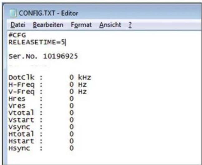
Figure 5-1. Example View - Config.txt.
NOTE: When using a USB combo device as a USB-HID input device, switching to a CPU Unit with activated USB-HID Ghosting may cause limited functionality.
6. Troubleshooting
6.1 General Failures
Table 6-1. General failures troubleshooting.
| Diagnosis Possible Reason Measure | |
| Config.txt parameter without function | Parameter not set or saved • Write parameter into Config.txt file and save changes. |
| Start Commanc #CFG not set • Write start command #CFG into first line of the Config.txt file. | |
| Parameter written incorrectly • Check correct spelling and capitalization. | |
| Extender not restarted • Restart extender. |
6.2 Blank Screen
CPU module, rear view CON module, rear view
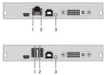
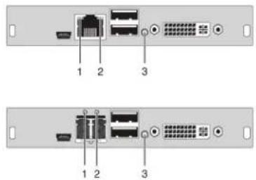
Figure 6-1. Blank screen.
Table 6-2. Blank screen troubleshooting.
| Diagnosis Possible Reason | Measure | |
| LED 3 off | Power supply | ·Check power supply units and the connection to the power network. |
| LED 1 on or LED 2 off | Connection between the CON unit and the CPU unit | ·Check interconnect cables and connections. |
| CPU unit: LED 3 red or yellow | No video signal detected by source (computer, CPU) | ·Check DVI-D cable to CPU.·Download DDC information from console monitors (see Chapter 5). Reboot CPU if necessary. |
| CON unit: LED 3 red or yellow | No monitor detected | ·Check connection, length, and quality of the DVI-D cable to monitor; tighten cable thumbscrews. |
| No video signal detected from CPU unit | ·Check connection, length, and quality of the interconnect cables between the units.·Download DDC information from console monitors (see Chapter 5). Reboot CPU if necessary. |
6.3 USB-HID
CPU module, rear view CON module, rear view
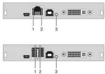
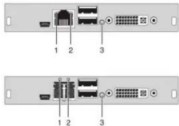
Figure 6-2. USB-HID module.
Table 6-3. USB-HID troubleshooting.
| Diagnosis Possible Reason Measure | ||
| Keyboard LEDs Shift and Scroll are blinking | Keyboard in command mode | • Pressto leave command mode |
| CPU unit: LED 3 green or violet No USB connection to CPU | • Check connection of USB cable to CPU; select another USB port if necessary.• Remove USB and power cable and restart CPU. Connect power cable first. | |
| CON unit: LED 3 green or violet Problems with USB connection | • Check connection of USB cable to USB-HID device.• Remove DVI and power cable and restart CON unit. Connect power cable first. | |
| USB device without function | No USB-HID device • Connect USB-HID device. | |
| USB-HID device is not supported | • Contact Black Box Technical Support at 724-746-5500 or info@blackbox.com if necessary. | |
6.4 Serial Connection
Table 6-4. Serial connection upgrade module troubleshooting.
| Diagnosis Possible Reason Measure | ||
| Serial device not operational | Settings of the serial interface | • Check baud rate and general settings. |
| No serial connection to CPU | • Check connection via serial cable. | |
| No serial connection to end device (for example, touchscreen, keyboard) | • Connect serial end device and switch it on.• Check connection via serial cable. | |
| Touchscreen not operational | Hardware handshake | • Adjust serial interface to X-ON/X-OFF software handshake. |
6.5 Analog Audio
Table 6-5. Analog audio troubleshooting.
| Diagnosis Possible Reason Measure | ||
| CON unit: No signal at audio output | No audio connection to CPU/audio source | Connect analog audio source.Check audio cable. |
| No signal | Switch analog audio source on.Activate analog output at CPU/audio source. | |
| No audio connection to audio sink (for example, speakers) | Connect analog audio sink and switch it on.Check connection of audio cable. | |
| CPU unit: No signal at audio output (microphone) | No audio connection to audio source (microphone) | Connect analog audio source (microphone).Check connection of audio cable. |
| No signal | Switch analog audio source on.Activate analog output at audio source. | |
| No audio connection to audio sink (for example, CPU) | Check connection to CPU.Check connection of audio cable.Check audio configuration. |
6.6 Digital Audio
CPU module, rear view CON module, rear view
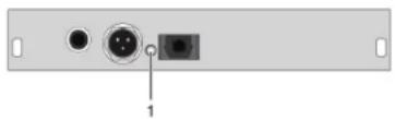
natural_image
Back panel of a computer interface showing two ports and a central connector (no text or symbols visible)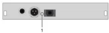
natural_image
Back panel of a computer interface showing two ports with a central connector (no text or symbols visible)Figure 6-3. Digital audio module.
Table 6-6. Digital audio upgrade module troubleshooting.
| Diagnosis Possible Reason Measure | ||
| CPU unit: LED 1 red | No audio connection to CPU/audio source | Connect digital audio source.Check connection of audio cable. |
| No signal | Switch digital audio source on.Activate digital output at CPU/audio source. | |
| CON unit: LED 1 red | No audio connection to audio sink (for example, speakers) | Connect digital audio sink.Check connection of audio cable. |
| No signal • Check signal at CPU unit. | ||
| No signalLEDs 1 OK Digital silence at active audio source | Check LEDs at CPU unit.Check audio format.Change audio input. | |
6.7 USB-HID Upgrade Module
CPU module, rear view CON module, rear view
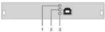
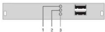
Figure 6-4. USB-HID at the basic module.
Table 6-7. USB-HID upgrade module troubleshooting.
| Diagnosis Possible Reason Measure | ||
| LEDs 1 and 2 off Device at higher/lower USB-HID port not detected | · Check connection of USB cable to USB-HID device.· Connect USB-HID device.· Contact Black Box Technical Support at 724-746-5500 or info@blackbox.com or your local Black Box subsidiary if necessary. | |
| CPU unit: LED 3 off Connection between CON unit and CPU unit · Check interconnect cable and connectors. | ||
| CON unit: LED 3 off Keyboard in command mode · Pressto leave command mode. | ||
| CON unit: LED 3 flashing slowly | Connection between CON unit and CPU unit · Check interconnect cable and connections. | |
| Keyboard in command mode · Pressto leave command mode. | ||
6.8 USB 2.0 Embedded
CPU module, rear view CON module, rear view
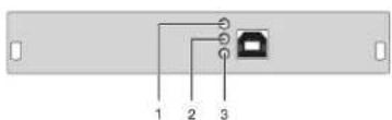
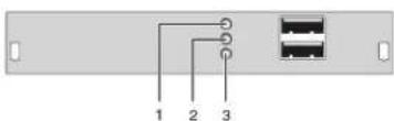
Figure 6-5. USB 2.0 Embedded.
Table 6-8. USB-HID upgrade module troubleshooting.
| Diagnosis Possible Reason Measure | ||
| CPU & CON Unit: LED 3 off | No connection to CPU | ·Check connection USB cable to CPU; select another USB port if necessary.·Remove USB and power cable and restart CPU. Connect power cable first. |
| CPU & CON Unit: LED 2 off | Connection between CON unit and CPU unit | ·Check interconnect cable and connectors. |
| CPU & CON Unit: LED 2 off and USB 2.0 device without function | No USB 2.0 device | ·Connect USB 2.0 device. |
| USB 2.0 device is not supported | ·Check installation at the CPU, also the necessary drivers.·New connection of the USB 2.0 device.·Contact dealer if necessary |
6.9 USB 2.0 Upgrade Module
CPU module, rear view CON module, rear view
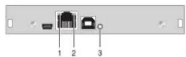
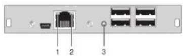
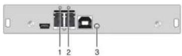
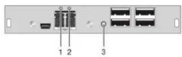
Figure 6-6. USB 2.0 upgrade module.
Table 6-9. USB 2.0 upgrade module troubleshooting.
| Diagnosis Possible Reason Measure | ||
| CPU unit: All LEDs off No connection to CPU | Check connection USB cable to CPU; select another USB port if necessary.Remove USB and power cable and restart CPU. Connect power cable first. | |
| CON unit: LED 3 red Connection between CON unit and CPU unit • Check interconnect cable and connectors. | ||
| CON unit: LED 3 flashing green/turquoise and USB 2.0 device without function | No USB 2.0 device • Connect USB 2.0 device. | |
| USB 2.0 device is not supported | Check installation at the CPU. Also check to make sure the CPU has the necessary drivers.New connection of the USB 2.0 device.Contact Black Box Technical Support at 724-746-5500 or info@blackbox.com if necessary. | |
7. Technical Support
7.1 Contacting Black Box
If you determine that your ServSwitch DKM Extender is malfunctioning, do not attempt to alter or repair the unit. It contains no user-serviceable parts. Contact Black Box Technical Support at 724-746-5500 or info@blackbox.com or your local Black Box subsidiary.
Before you do, make a record of the history of the problem. We will be able to provide more efficient and accurate assistance if you have a complete description, including:
- the nature and duration of the problem.
- when the problem occurs.
- the components involved in the problem.
- any particular application that, when used, appears to create the problem or make it worse.
7.2 Shipping and Packaging
If you need to transport or ship your ServSwitch DKM Extender:
- Package it carefully. We recommend that you use the original container.
- If you are returning the unit, make sure you include everything you received with it. Before you ship for return or repair, contact Black Box to get a Return Authorization (RA) number.
8. Glossary
The following terms are commonly used in this guide or in video and KVM technology:
Access: A system to operate a source (computer, CPU) from two consoles.
AES/EBU: Digital audio standard that is officially known as AES3. It's used to carry digital audio signals between devices.
CATx: Any CAT5e (CAT6, CAT7) cable
CGA: The Color Graphics Adapter (CGA) is an old analog graphic standard that displays up to 16 colors and at a maximum resolution of 640 x 400 pixels.
Component Video: The Component Video (YPbPr) is a high-quality video standard that consists of three independently and separately transmittable video signals: the luminance signal and two color difference signals.
Composite Video: The Composite Video is also called FBAS and it is part of the PAL TV standard.
CON module: Component of a DKM Modular Extender or Media Extender to connect to the console (monitor(s), keyboard and mouse; optionally also with USB 2.0 devices).
Console: Keyboard, mouse and monitor.
CPU module: Component of a DKM Modular Extender or Media Extender to connect to a source (computer, CPU).
DDC: The Display Data Channel (DDC) is a serial communication interface between monitor and source (computer, CPU). It can exchange data via a monitor cable and the operating system can install and configure a monitor driver automatically.
Dual-Head: A system with two video connections.
Dual-Link: A DVI-D interface for resolutions up to 2560 x 2048 that transmits signals up to 330 MPixel/s (24-bit)
DVI: Digital video standard, introduced by the Digital Display Working Group (http://www.ddwg.org). Single-Link and Dual-Link standard are distinguished. The signals have TMDS level.
DVI-I: A combined signal (digital and analog) that allows running a VGA monitor at a DVI-I port—in contrast to DVI-D (see DVI).
EGA: The Enhanced Graphics Adapter (EGA) is an old analog graphics standard, introduced by IBM in 1984. It uses a DB9 connector for connection.
FBAS: The analog color video baseband signal (FBAS) is also called Composite Video and it is part of the PAL TV standard.
Fiber: Single-mode or multimode fiber cables.
KVM: Keyboard, video and mouse.
Mini-XLR: Industrial standard for electrical plug connections (3-pole) for the transmission of digital audio and control signals.
Multimode: 62.5μ fiber cable or 50μ fiber cable
OSD: The on-screen-display displays information or operates a device.
Quad-Head: A system with four video connections.
RCA (Cinch): A non-standardized plug connection that transmits electrical audio and video signals, especially with coaxial cables.
SFP: Small Form Factor Pluggable (SFPs) are pluggable interface modules for Gigabit connections. SFP modules are available for CATx and fiber interconnect cables.
Single-Head: A system with one video connection.
Single Link: A DVI-D interface that supports resolutions up to 1920 x 1200 by transmitting signals up to 165 Megapixels per second (24-bit). Alternative frequencies are Full HD (1080p), 2K HD (2048 x 1080), and 2048 x 1152.
Single-mode: 9μ fiber cable
S/PDIF: A digital audio interconnect that is used in consumer audio equipment over relatively short distances.
S-Video (Y/C): The S-Video (Y/C) is a video format that transmits luminance and chrominance signals separately. It has a higher quality standard than FBAS.
TOSLINK: Standardized fiber connection system that digitally transmits audio signals (F05 plug connection).
Triple-Head: A system with three video connections.
USB-HID: USB-HID devices (Human Interface Device) allow for data input. There is no need for a special driver during installation; "New USB-HID device found" is reported. Typical HID devices include keyboards, mice, graphics tablets, and touchscreens. Storage, video, and audio devices are not HID.
VGA: Video Graphics Array (VGA) is a computer graphics standard with a typical resolution of 640 x 480 pixels and up to 262,144 colors. It follows the graphics standards MDA, CGA and EGA.
Black Box Tech Support: FREE! Live. 24/7.
Tech support the way it should be.

natural_image
Close-up portrait of a smiling man with short hair holding a small object, against a blue gradient background (no text or symbols visible)Great tech support is just 60 seconds away at 877-877-2269 or BlackBox.com.

BLACK BOX®
About Black Box
Black Box provides an extensive range of networking and infrastructure products. You'll find everything from cabinets and racks and power and surge protection products to media converters and Ethernet switches all supported by free, live 24/7 Tech support available in 60 seconds or less.
© Copyright 2016. Black Box Corporation. All rights reserved. Black Box ^® and the Double Diamond logo are registered trademarks of BB Technologies, Inc. Any third-party trademarks appearing in this manual are acknowledged to be the property of their respective owners.
ACX1MR_T-user_rev5
- DKM KVM Extender TX/RX Interface Modules
- Increase the distance between a source (computer, CPU) and its console (keyboard, mouse, and other peripheral devices).
- Trademarks Used in this Manual
- Disclaimer
- Federal Communications Commission and Industry Canada Radio Frequency Interference Statements
- CE Declaration of Conformity
- Disclaimer:
- Interconnect Cable 13
- Supported Peripherals....15
- Connector Pinouts 15
- Power Supply, Environmental Conditions, Dimensions, and Shipping Weight....23
- Overview 24
- Accessories Upgrade Kits 31
- Accessories....31
- Device Views 32
- Installation 74
- Example Applications....77
- Configuration 80
- Operation 85
- Troubleshooting 87
- Technical Support Information....92
- Glossary 93
- Safety Instructions
- Installation
- Repair
- Specifications
- Interfaces
- DVI-D Single Link
- DVI-D Dual Link
- DVI-I Single Link
- HDMI Single Link
- Video
- Audio
- 3D
- DisplayPort
- USB-HID
- Keyboard
- Mouse
- Other USB-HID devices
- PS/2
- USB 2.0 (transparent)
- RJ-45 (Interconnect)
- Fiber SFP Type LC (Interconnect)
- Serial Interface
- Operation of several devices:
- Serial Interface RS-422
- Analog Audio Interface
- Connection of a microphone:
- Digital Audio Interface
- Interconnect Cable
- CATx
- Type of Interconnect Cable
- Maximum Acceptable Cable Length
- Fiber
- Connector type
- Supported Peripherals
- USB-HID Devices
- USB 2.0 Devices
- Connector Pinouts
- 3.5-mm Stereo Jack Plug
- Power Supply, Environmental, Dimensions, and Shipping Weight
- Overview
- Application
- System Overview
- Part Numbers
- Chassis
- KVM Extender Modules
- Upgrade Modules
- Chassis for Free Configuration
- Upgrade Kits
- Accessories
- Device Views
- Compatible Chassis
- ACXMODH2R-R2 and Compatible Accessories
- ACXMODH2R-P-R2 and Compatible Accessories
- ACXMODH4-R2 and Compatible Accessories
- ACXMODH4R-R2 and Compatible Accessories
- ACXMODH6R-R2 and Compatible Accessories
- ACXMODH6BPAC-R2 and Compatible Accessories
- ACXMODH6FPAC-R2 and Compatible Accessories
- ACXMODH21R and Compatible Accessories
- ACX1MT-DHID-C/ACX1MR-DHID-C
- ACX1MT-VDHID-C /ACX1MR-VDHID-C
- Basic Module ACX1MT-DHID-SM/ACX1MR-DHID-SM
- ACX1MT-DHS-SM/ACX1MR-DHS-SM
- ACX1MT-VHID-SM/ACX1MR-VHID-SM
- ACX1MT-DHID-2C/ACX1MR-DHID-2C
- Rear view
- ACX1MT-VDHID-2S/ACX1MR-VDHID-2S
- Rear view Rear view
- ACX1MT-DHID-2S/ACX1MR-DHID-2S
- ACX1MT-VDHID-2S/ACX1MR-VDHID-2S
- Basic Module ACX1MT-DVHID-C/ACX1MR-DVHID-C
- Basic Module ACX1MT-DVHID-SM/ACX1MR-DVHID-SM
- ACX2MT-DLH-C/ACX2MR-DLH-C
- ACX2MT-DHH-C/ACX2MR-DHH-C
- ACX2MT-DLH-SM/ACX2MR-DLH-SM
- ACX2MT-DHH-SM/ACX2MR-DHH-SM
- ACX2MT-DHHS-SM/ACX2MR-DHHS-SM
- ACX2MT-DLHS-SM/ACX2MR-DLHS-SM
- ACX2MT-DLH-2C/ACX2MR-DLH-2C
- ACX2MT-DHH-2C/ACX2MT-DHH-2C
- ACX2MT-DLH-SM/ACX2MT-DLH-SM
- ACX1MT-HDMI-C/ACXMR-HDMI-C
- ACX1MT-HDMI-2C/ACX1MR-HDMI-2C
- ACX1MT-HDM2-C
- ACX1MT-HDM2-2C
- ACX1MT-HDMI-SM/ACX1MR-HDMI-SM
- ACX1MT-HDMI-SM/ACX1MR-HDMI-SM
- ACX1MT-HDM2-SM/ACX1MR-HDM2-SM
- ACX1MT-HDM2-2S
- ACX1MR-HDSW-C
- ACX1MR-HDSW-2C
- ACX1MR-HDSW-SM
- ACX1MR-HDSW-2S
- ACX1MT-HDO-C /ACX1MR-HDO-C
- ACX1MT-HDO-SM/ACX1MR-HDO-SM
- ACX2MT-DPH-C/ACX2MR-DPH-C
- ACX2MT-DPH-SM/ACX2MR-DPH-SM
- ACX2MT-DPHS-SM/ACX2MR-DPHS-SM
- ACX2MT-DPH-2C/ACX2MR-DPH-2C
- ACX2MT-DPH-2S/ACX2MR-DPH-2S
- ACX2MT-DPHS-2S/ACX2MR-DPHS-2S
- Upgrade Module ACX1MT-HID/ACX1MR-HID
- ACX1MT-EU/ACX1MR-EU
- Upgrade Module ACX1MT-AR/ACX1MR-AR
- ACX1MT-ARP/ACX1MR-ARP
- Upgrade Module ACX1MT-DA/ACX1MR-DA
- Upgrade Module ACX1MT-ARH/ACX1MR-ARH
- Upgrade Module ACX1MT-DAH/ACX1MR-DAH
- ACX1MT-ARE/ACX1MR-ARE
- ACX1MT-DAE/ACX1MR-DAE
- Upgrade Module ACX1MT-DAX/ACX1MR-DAX
- Upgrade Module ACX1MT-ARD/ACX1MR-ARD
- USB 2.0 Module ACX1MT-U2-C/ACX1MR-U2-C
- USB 2.0 Module ACX1MT-U2-SM/ACX1MR-U2-SM
- USB 2.0 Module ACX1MT-U23-C/ACX1MR-U23-C
- USB 2.0 Module ACX1MT-U23-SM/ACX1MR-U23-SM
- ACX2MT-DPH4KHS-SM/ACX2MR-DPH4KHS-SM
- ACX2MT-DPH-2S/ACX2MR-DPH-2S
- Status LEDs
- KVM Extender Module Status
- KVM Extender Module VGA/DVI-I Status
- Upgrade Module Digital Audio Status
- Upgrade Module USB-HID Status
- Upgrade Module USB 2.0 Embedded Status
- USB 2.0 Module Status
- Installation
- Package Contents
- KVM Extender:
- System Setup
- KVM Extender Module Setup
- Setup of Upgrade Modules
- Upgrade Module USB-HID:
- Upgrade Module PS/2:
- Upgrade Module USB 2.0 Embedded:
- Upgrade Module USB 2.0:
- Example Applications
- Configuration
- Transmission Parameters
- DDC Settings
- Uploading DDC Information
- Retrieving DDC Information
- Reset to Factory DDC Information
- Command Mode
- Set freely selectable "Hot Key" (exemplary)
- Reset "Hot Key"
- USB-HID Ghosting
- Configuration File
- Parameters for CPU Units
- Parameters for CON Units
- Parameters for CPU und CON Units
- Operation
- Download of DDC Information
- Shared Operation of redundant CPU Units
- Troubleshooting
- General Failures
- Blank Screen
- USB-HID
- Serial Connection
- Analog Audio
- Digital Audio
- USB-HID Upgrade Module
- USB 2.0 Embedded
- USB 2.0 Upgrade Module
- Technical Support
- Contacting Black Box
- Shipping and Packaging
- Glossary
- Black Box Tech Support: FREE! Live. 24/7.
- BLACK BOX®
- About Black Box
Brand : Black Box
Model : ACX2MT-DP4KHS
Category : Network switch