
KX-HNC600E - Home Automation PANASONIC - Free user manual and instructions
Find the device manual for free KX-HNC600E PANASONIC in PDF.
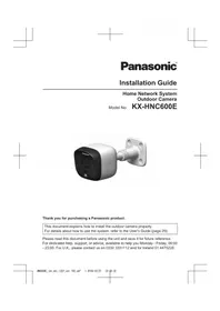


| Product Type | Smart Home IP Camera |
| Dimensions (H x W x D) | 115 x 67 x 67 mm |
| Weight | 150 g |
| Power Supply | 5 V DC, 1 A (micro USB) |
| Video Resolution | 1080p Full HD |
| Night Vision | Up to 10 m with IR LEDs |
| Field of View | 130° diagonal |
| Two-Way Audio | Built-in microphone and speaker |
| Motion Detection | Yes, with push notifications |
| Storage | microSD card up to 128 GB (not included) or cloud |
| Connectivity | Wi-Fi 802.11 b/g/n (2.4 GHz) |
| Compatibility | Amazon Alexa, Google Assistant |
| Privacy Mode | Yes, lens shutter |
| Cleaning Instructions | Wipe with a soft, dry cloth. Do not use liquids. |
| Security | Encrypted video (TLS/SSL) |
| Replacement Parts | Power adapter and USB cable only |
| Repairability | Non-user serviceable; contact support for issues |
| Mounting | Tabletop stand or wall mount (bracket included) |
Frequently Asked Questions - KX-HNC600E PANASONIC
User questions about KX-HNC600E PANASONIC
0 question about this device. Answer the ones you know or ask your own.
Ask a new question about this device
Download the instructions for your Home Automation in PDF format for free! Find your manual KX-HNC600E - PANASONIC and take your electronic device back in hand. On this page are published all the documents necessary for the use of your device. KX-HNC600E by PANASONIC.
USER MANUAL KX-HNC600E PANASONIC
Model No. KX-HNC600E

Thank you for purchasing a Panasonic product.
This document explains how to install the outdoor camera properly.
For details about how to use the system, refer to the User's Guide (page 29).
Please read this document before using the unit and save it for future reference.
For dedicated help, support, or advice, available to help you Monday - Friday, 09:00
- 23:00. For U.K., please contact us on 0330 3331112 and for Ireland 01 4475228.
Table of Contents
Introduction
Accessory information ....3
General information 4
Using Panasonic Home Network
System 5
Important Information
About this system 7
For your safety 7
Important safety instructions ....8
For best performance ....8
Privacy and rights of portrait ......9
Other information 9
Installation Location
Wireless communication range .....11
Information about sensor features .....11
Information about night vision mode .....13
Installation location examples ....14
Do not install in these locations .....16
Setup
Part names and functions ......18
LED indicator 18
Setup overview ......18
Registering the camera 19
Confirming the installation area .....19
Installation 20
Appendix
Testing the motion detection range .....25
Adjusting the infrared sensor range .....25
Features available when using the [Home
Network] app ......29
Accessing the User's Guide ......29
Specifications 30
Conditions of guarantee ....31
Accessory information
Supplied accessories
| No. | Accessory item/Part number Quantity | |
| 1 | AC adaptor/PNLV236E0Y 1 | |
| 2 | Camera mounting stand/PNZB1002Z 1 | |
| 3 | Wall mounting screws (25 mm)/XTB4+25AVW 4 | |
| 4 | Suspension wire tool- Safety wire: 1PQME10080Z-Washers: 2Small washer for attaching safety wire to cameraø12 mm/XWG26D12VWLarge washer for attaching safety wire to wallø16 mm/PNXWG4F16VW-Screws: 2Small screw for attaching safety wire to camera10 mm/XTB26+10GVWLarge screw for attaching safety wire to wall25 mm/XTB4+25AVW | 1 |
| 5 | Sensor range cap/PNHG1210Z 1 |


Additional accessories
Please contact your nearest Panasonic dealer for sales information.
| Accessory item Order number | |
| DC extension cord 1 | PNJA1159Z |

*1 Designed for indoor use only. Do not use outdoors.
Other information
- Design and specifications are subject to change without notice.
- The illustrations in these instructions may vary slightly from the actual product.
Introduction
Trademarks
- microSDHC is a trademark of SD-3C, LLC.
- iPhone and iPad are trademarks of Apple Inc., registered in the U.S. and other countries.
- Android is a trademark of Google Inc.
- Microsoft, Windows, and Internet Explorer are either registered trademarks or trademarks of Microsoft Corporation in the United States and/or other countries.
- All other trademarks identified herein are the property of their respective owners.
Sales and support information
Customer Communications Centre
• For customers within the U.K.: 0330 3331112 • For customers within Ireland: 01 4475228 - For further support on your product, please visit our website: www.panasonic.co.uk
Direct Sales at Panasonic U.K.
- Order accessory and consumable items for your product with ease and confidence by phoning our Customer Communications Centre Monday - Friday 9:00am - 5:00pm (Excluding public holidays).
- Go online through our Internet Accessory ordering application at www.pas-europe.com
- Most major credit and debit cards accepted.
- All enquiries, transactions and distribution facilities are provided directly by Panasonic U.K.
Notice
- The hub supports microSD and microSDHC memory cards. In this document, the term "microSD card" is used as a generic term for any of the supported cards.
General information
Declaration of Conformity:
- Panasonic Corporation declares that the radio equipment type (KX-HNC600) is in compliance with Directive 2014/53/EU. The full text of the EU declaration of conformity is available at the following internet address:
http://www.ptc.panasonic.eu/doc
Contact to Authorised Representative:
Panasonic Testing Centre
Panasonic Marketing Europe GmbH
Winsbergring 15, 22525 Hamburg, Germany
Ecodesign information
Ecodesign information under EU Regulation (EC) No. 1275/2008 amended by (EU) Regulation No. 801/2013. From 1 January 2015.
Please visit here: http://www.ptc.panasonic.eu/erp
Click [Downloads]
4
Helpline Tel. No.: U.K. 0330 3331112 Ireland 01 4475228
→ Energy related products information (Public)
Power consumption in networked standby and guidance are mentioned in the web site above.
For your future reference
We recommend keeping a record of the following information to assist with any repair under warranty.
Serial No. Date of purchase
(found on the rear of the unit)
Name and address of dealer
Attach your purchase receipt here.
Using Panasonic Home Network System
Thank you for purchasing Panasonic Home Network System products.
This guidance is provided to help you understand how you should use Panasonic Home Network system to comply with current UK laws. This information is for general guidance on your rights and responsibilities and is not legal advice. If you need more details on your rights and responsibilities or legal advice about how to use CCTV cameras, please contact an adviser or solicitor. You can also find more information on the Information Commissioner's (ICO) website.
Where can I install CCTV cameras?
- If you own your home, you do not need any permission to fit the cameras on or in it.
- If you do not own your home, you will need written permission from the landlord or owner of the property before installing any cameras.
- You must not fit your cameras on a neighbour's property without their consent; you will need to obtain written permission before installing any cameras on someone else's property.
- You must not fit cameras onto any street lighting columns, trees, public buildings, or public fencing without written consent from the responsible authority.
What can I monitor with my CCTV system?
If you are planning to install cameras for monitoring parts of the street or any other areas outside your own property, please refer to the Data Protection Act 1998 and related ICO guidance to know your rights and responsibilities and to clarify what you can and cannot monitor.
Personal data processed by an individual only for the purposes of that individual's personal, family, or household affairs are exempt from the Data Protection Act 1998, therefore you can freely install CCTV cameras for these purposes within your own property.
Introduction
Can I point my cameras at my neighbour's property?
You must respect your neighbour's right to privacy. CCTV should not be directed into someone else's home or property. If you misuse your CCTV system, you could face criminal or civil consequences. Using CCTV to infringe on another person's privacy on more than one occasion could be considered harassment, which is a serious criminal/civil offence. Using CCTV images for voyeuristic or anti-social purposes are also offences that the police can deal with under criminal law.
Do I need to display CCTV signs?
No, if cameras are only monitoring within your property.
However, for monitoring outside your property, it is strongly recommended to display signs, and in any event you must comply with the Data Protection Act 1998 and related ICO guidance. In addition, signs informing people they are entering an area covered by CCTV may help deter individuals from committing offences against you or your property.
Panasonic may update this guidance from time to time. For the current version please refer to: www.panasonic.co.uk/SmartHome/Usage
*1 as of 14/04/15
Disclaimer
Panasonic shall not have any liability if the CCTV system is used in any way contrary to the Data Protection Act 1998, related guidance or any other laws or legal requirements.
Important Information
About this system
- This system is an auxiliary system; it is not designed to provide complete protection from property loss. Panasonic will not be held responsible in the event that property loss occurs while this system is in operation.
- The system's wireless features are subject to interference, therefore functionality in all situations cannot be guaranteed. Panasonic will not be held responsible for injury or damage to property that occurs in the event of wireless communication error or failure.
For your safety
To prevent severe injury and loss of life/property, read this section carefully before using the product to ensure proper and safe operation of your product.

WARNING
Power connection
- Use only the power source marked on the product.
- Do not overload power outlets and extension cords. This can result in the risk of fire or electric shock.
- Completely insert the AC adaptor/power plug into the power outlet. Failure to do so may cause electric shock and/or excessive heat resulting in a fire.
- Regularly remove any dust, etc. from the AC adaptor/power plug by pulling it from the power outlet, then wiping with a dry cloth. Accumulated dust may cause an insulation defect from moisture, etc. resulting in a fire.
- Unplug the product from power outlets if it emits smoke, an abnormal smell, or makes an unusual noise. These conditions can cause fire or electric shock. Confirm that smoke has stopped emitting and contact an authorised service centre.
- Unplug from power outlets and never touch the inside of the product if its casing has
been broken open. Danger of electric shock exists.
- Never touch the plug with wet hands. Danger of electric shock exists.
- Do not connect non-specified devices.
- When opening holes in walls for installation or wiring, or when securing the power cord, make sure you do not damage existing wiring and ductwork.
- Do not leave the power cable exposed outdoors.
Installation
- Do not place or use this product near automatically controlled devices such as automatic doors and fire alarms. Radio waves emitted from this product may cause such devices to malfunction resulting in an accident.
- Do not allow the power cord to be excessively pulled, bent or placed under heavy objects.
- Do not mount the bracket in an unstable location, in a location subject to frequent vibration, on a ceiling, or on a weak wall. (Do not mount on gypsum board, concrete blocks, wooden materials exposed to the outdoors, walls with very rough surfaces, or surfaces that are narrower than the width of the wall mount bracket.) There is a risk of injury if the product falls, or of fire or electric shock if water enters the product.
- Keep small parts (microSD cards, screws, washers, sensor range caps, etc.) out of the reach of children. There is a risk of swallowing. In the event they are swallowed, seek medical advice immediately.
Operating safeguards
- Unplug the product from power outlets before cleaning. Do not use liquid or aerosol cleaners.
- Do not disassemble the product.
- Keep the sensor range caps out of the reach of children. There is a risk of swallowing. In the event they are swallowed, seek medical advice immediately.
- Never put metal objects inside the product. If metal objects enter the product, turn off
Important Information
the circuit breaker and contact an authorised service centre.
Medical
- Consult the manufacturer of any personal medical devices, such as pacemakers or hearing aids, to determine if they are adequately shielded from external RF (radio frequency) energy. DECT features operate between 1.88 GHz and 1.90 GHz with a peak transmission power of 250 mW.
- Do not use the product in health care facilities if any regulations posted in the area instruct you not to do so. Hospitals or health care facilities may be using equipment that could be sensitive to external RF energy.
CAUTION
Installation and location
- Never install wiring during a lightning storm.
- Although this product conforms to the IPX5* code, do not intentionally expose it to water. *IPX5 indicates that the product is protected against water jets: water projected at all angles through a 6.3 mm nozzle flow rate of 12.5 litres/minute at a pressure of 30 kN/m^2 for 3 minutes from a distance of 3 metres.
- The AC adaptor is used as the main disconnect device. Ensure that the AC outlet is installed near the product and is easily accessible.
- If the wiring is underground, do not make any connections underground.
- If the wiring is underground, make sure the power cable and other wiring is properly waterproofed by running the cables through a conduit.
Preventing accidents and injuries
- The safety wire must be used when mounting the product. There is a risk of injury if the product falls.
- Do not put your ear(s) near the speaker, as loud sounds emitted from the speaker may cause hearing impairment.
Important safety instructions
When using your product, basic safety precautions should always be followed to reduce the risk of fire, electric shock, and injury to persons, including the following:
- Use only the power cord indicated in this document.
SAVE THESE INSTRUCTIONS
For best performance
Hub location/avoiding noise
The hub and other compatible Panasonic devices use radio waves to communicate with each other.
- For maximum coverage and noise-free communications, place your hub: – at a convenient, high, and central location with no obstructions between the product and hub in an indoor environment. – away from electronic appliances such as TVs, radios, personal computers, wireless devices, or other phones. – facing away from radio frequency transmitters, such as external antennas of mobile phone cell stations. (Avoid putting the hub on a bay window or near a window.)
- If the reception for a hub location is not satisfactory, move the hub to another location for better reception.
Environment
- Keep the product away from electrical noise generating devices, such as fluorescent lamps and motors.
- The product should be kept free from excessive smoke, dust, high temperature, and vibration.
- Do not expose this product to direct sunlight or other forms of powerful light such as halogen lights for long periods of time. (This may damage the image sensor.)
- Do not place heavy objects on top of the product.
- When you leave the product unused for a long period of time, unplug the product from the power outlet.
- The product should be kept away from heat sources such as radiators, cookers, etc. It should not be placed in rooms where the temperature is less than -20 °C or greater than 50 °C. Damp basements should also be avoided.
- Do not allow the lens cover or the infrared sensor to become scratched or dirty. (This may cause image quality to be reduced, incorrect detections, malfunctions, or damage to the lens cover and infrared sensor.)
- Operating the product near electrical appliances may cause interference. Move away from the electrical appliances.
Privacy and rights of portrait
When installing or using the camera, please take into consideration the rights of others with regard to privacy.
It is generally said that “privacy” means the ability of an individual or group to stop information about themselves from becoming known to people other than those whom they choose to give the information. “Rights of portrait” means the right to be safe from having your own image taken and used indiscriminately without consent.
Other information
Routine care
- To prevent incorrect detections, unplug the product before performing routine care.
- Wipe the outer surface of the product with a soft moist cloth.
- Do not use benzine, thinner, or any abrasive powder.
- Do not apply running water to the product.
Camera image quality
- Camera images may have the following characteristics. – Colours in images may differ from the actual colours.
- When there is light behind the subject (i.e., backlighting), faces may appear dark. – Image quality may be reduced in dark locations. – Images may appear hazy when there are outdoor lights in use.
Protecting your recordings
- Do not remove the microSD card or disconnect the hub's AC adaptor while reading or writing data to the microSD card. Data on the card could become corrupted.
- If a microSD card malfunctions or is exposed to electromagnetic waves or static electricity, data on the card could become corrupted or erased. Therefore we recommend backing up important data to a computer or other device.
Important Information
Disposal of Old Equipment (Only for European Union and countries with recycling systems)


This symbol on the products, packaging, and/or accompanying documents means that used electrical and electronic products must not be mixed with general household waste.
For proper treatment, recovery and recycling of old products, please take them to applicable collection points in accordance with your national legislation.
By disposing of them correctly, you will help to save valuable resources and prevent any potential negative effects on human health and the environment. For more information about collection and recycling, please contact your local municipality.
Penalties may be applicable for incorrect disposal of this waste, in accordance with national legislation.
For business users in the European Union
If you wish to discard electrical and electronic equipment, please contact your dealer or supplier for further information.
Information on Disposal in other Countries outside the European Union
This symbol is only valid in the European Union. If you wish to discard these items, please contact your local authorities or dealer and ask for the correct method of disposal.
Wireless communication range
The wireless communication range of each device in the system from the hub is approximately 50 m indoors and approximately 300 m outdoors. Wireless communication may be unreliable when the following obstacles are located between the hub and other devices.
• Metal doors or screens - Walls containing aluminium-sheet insulation - Walls made of concrete or corrugated iron • Double-pane glass windows - Multiple walls - When using each device on separate floors or in different buildings
Note:
- The camera's LED indicator blinks in red if it is out of range of the hub. In this case, confirm all connections, including those of the hub.
Information about sensor features
The camera has 2 sensor features that are used for motion detection: a visual sensor and an infrared sensor (i.e., heat sensor).
Please read the following information before deciding where to install the camera.
Note:
- The camera's sensor features are not designed to be used in situations that require high reliability. We do not recommend use of the sensor features in these situations.
- Panasonic takes no responsibility for any injury or damage caused by the use of the camera's sensor features.
Detection method
| Visual sensor Infrared sensor | |
| The camera detects changes in the images being displayed.● The camera detects changes in the brightness levels of moving objects. | The camera detects temperature differences of objects in the images being displayed.● The infrared sensor uses infrared rays to detect temperature differences within its range that are emitted naturally by people, animals, etc. |
Installation Location
Detection range
| Visual sensor Infrared sensor | |
Can detect motion anywhere in the visible image. • Yu can adjust the area detectable by the visual sensor. For more information, refer to the User's Guide (page 29). • Yu can adjust the area detectable by the visual sensor. For more information, refer to the User's Guide (page 29). | Can detect motion only in part of the visible image (shown here in grey) • Yu can adjust the area detectable by the infrared sensor. See “Adjusting the infrared sensor range”, page 25.• Detection does not occur when there are obstacles in front of the infrared sensor. Remove the obstacles or change the installation location. • Yu can adjust the area detectable by the infrared sensor. See “Adjusting the infrared sensor range”, page 25.• Detection does not occur when there are obstacles in front of the infrared sensor. Remove the obstacles or change the installation location. |
Main characteristics
| Visual sensor Infrared sensor | |
| Easily detects movement in the daytime or when it is bright.Movement may be incorrectly detected when the moving object and the background have a similar colour.Movement may be incorrectly detected when there are sudden changes to the overall brightness levels such as when external lights are used. | Easily detects when there is a big difference between the temperatures of objects and the surrounding environment, such as in winter or late at night.The sensor cannot easily detect when there is no difference between the temperatures of objects and the surrounding environment, such as in summer or during the daytime.If the camera is mounted facing a road, the sensor may detect incorrectly due to interference caused by the heat from passing cars. |
Direction of motion
It is easier to detect objects that move sideways in front of the camera, and more difficult to detect objects that move directly toward the front of the camera.

① It is difficult to detect movement directly towards the front of the camera. ② It is easy to detect movement sideways in front of the camera. ③ Detection range ④ Camera
Information about night vision mode
The camera features an array of infrared LEDs that light automatically in low-light conditions, allowing camera images to be viewable even when the surrounding area is dark.
Note:
- When night vision mode is active, the colours in camera images may appear different from normal.
- When night vision mode is active, the array of infrared LEDs that surround the camera's lens light up in a faint red colour that can be seen in the dark.
- If the camera is installed in front of a window and points directly at the window, images may be poor when night vision mode is active.
Installation location examples
I want to detect visitors approaching the house
Refer to the table below for detecting visitors at an entrance or gate without detecting cars in the street.

I want to detect people entering the garage
Refer to the table below for detecting people entering a garage without detecting cars in the street.
| Ideal example Poor example | |
 Visitors pass in front of the camera from side to side, cars in the street are less likely to cause false detections.To prevent faces from being obscured by tall vehicles, adjust the installation position and angle of the camera. Visitors pass in front of the camera from side to side, cars in the street are less likely to cause false detections.To prevent faces from being obscured by tall vehicles, adjust the installation position and angle of the camera. |  Cars in the street are more likely to cause false detections. Cars in the street are more likely to cause false detections. |
Do not install in these locations
Installing in the following areas may cause deformation, discolouration, malfunction, or operational failure
- In direct sunlight or directly under an outdoor light (even if the surroundings are within operational temperature range, parts of the product may become hot)
- Areas subject to frequent vibration, shock, or impact
- Near fire, heating devices, magnetic fields (such as near magnets), or air conditioners (including outdoor equipment such as unit compressors)
- Areas exposed to grease or steam
- Near devices that emit strong radio waves, such as mobile phones
- Areas subject to extreme temperature changes (which can lead to condensation)
- Near coasts directly subjected to sea breezes, or near sulphuric hot springs (exposure to salt can shorten the life of the product)
- Near TVs, radios, automated office equipment such as computers, air conditioners, water heater panels (with intercom), or home security equipment (these may cause noise)
- Near satellite broadcasting receivers such as tuners, TVs with built-in satellite tuners, and recorders (broadcasted images may be distorted)
- Areas where hydrogen sulphide, ammonia, dust, or toxic gases are present
Installing in the following areas may cause false detections
Areas where people approach directly from the front of the camera, such as narrow walkways
Camera B: Difficult to detect

Areas where objects such as trees or hanging laundry move due to wind (temperature variation and motion may cause false detections)

On roads with high traffic (passing cars may cause sensor detections even if they are 5 m or more away)

Installation Location
Areas affected by breezes from fans, air conditioning unit compressors, water heaters, or car exhaust (severe temperature variations may cause false detections)

- Areas subject to severe weather, such as strong wind (camera shake can cause false detections) or rain (strong rain may be detected as an object moving in front of the camera)
- Areas with reflective objects, such as glass, that can interfere with detection of temperature variation
- Areas where brightness changes easily (such as areas where shadows form in the afternoon and lights turn on at night)
- Areas where backlight occurs (faces appear dark and are difficult to identify), such as the following
– Areas where most of the background is the sky – Areas where direct sunlight reflects off a white wall or background – Bright areas such as those exposed to direct sunlight
Setup
Part names and functions
① Microphone ② Sensor range cap (Standard) ③ Infrared sensor ④ LED indicator ⑤ Lens unit ⑥ Speaker ⑦ [·]B
Used when registering the camera to the hub.
8 Safety wire 9 Camera mounting stand 10 DC cable
LED indicator
You can use the LED indicator to confirm the camera's status.
| Indicator Status | |
| Off No power, or LED | indicator is turned off*1 |
| Green, lit | Normal operation*1 |
| Green, blinking slowly | Registration mode |
| Red Motion detected |
| Indicator Status | |
| Red, blinking slowly Live images are being viewed or recorded | |
| Red, blinking Camera is out of range of the hub, or device malfunction | |
| Amber, blinking slowly | Camera is not registered to a hub |
*1 You can configure the camera so that its LED indicator does not light during normal operation. For more information, refer to the User's Guide (page 29).
Setup overview
1 | Initial setup
Make sure you can access the system using your mobile device. For details, refer to the System Setup Guide included with your hub.
2 Registration
Required only if the camera was purchased separately (i.e., not as part of a bundle).
3 Confirm the installation area
Read the information in this document to confirm that the desired installation area is suitable for proper operation.
4 Installation
Install the camera in the desired location and connect the camera to the power outlet.
5 Adjust the infrared sensor range
Confirm the sensor range area and adjust it if necessary using the included sensor range adjustment caps.
Registering the camera
This procedure is not required for devices that were included as part of a bundle.
Before you can use the camera, it must be registered to the hub.
If the camera is not registered to a hub, the camera's LED indicator blinks slowly in amber. You can register each device by using the registration buttons or the [Home Network] app.
Note:
- Before registering the camera, make sure the AC adaptors of the hub and camera are connected and each device is powered.
Using registration buttons
1 Hub:
Press and hold [●●●]B CAMERA] until the LED indicator blinks slowly in green.
2 Camera:
Using an object with a thin tip, press and hold [●●●] until the LED indicator blinks slowly in green (page 18).
- When registration is complete, the hub sounds one long beep.

Note:
- To cancel without registering the camera, press [•••]B on the hub and on the camera again.
- If registration fails, the hub sounds several short beeps.
Using the app
When you register the camera using the [Home Network] app, you can assign a name to your devices and group them by location. For more information, refer to the User's Guide (page 29).
Confirming the installation area
Before deciding where to install the camera, carefully read the chapter "Installation Location", beginning on page 11, to confirm the installation location and direction.
Setup
Installation
Installation precautions
- Do not install the camera on a ceiling.
- Holes must be made in the wall for cables and wires to pass through. Panasonic takes no responsibility for issues related to opening holes in walls.
- Make sure to waterproof the holes you make in the wall. ● Make sure you attach the safety wire to prevent the camera from falling.
- Do not use an impact driver. (This may lead to damaged screws or over-tightening.)
- Mount the camera on a stable location where the unit can be adequately supported when installing.
- The AC adaptor should be connected to a vertically oriented or floor-mounted AC outlet. Do not connect the AC adaptor to a ceiling-mounted AC outlet, as the weight of the adaptor may cause it to become disconnected.
- Do not mount the camera on a soft material. It may fall down, break or cause injury.
Wall material information
Siding
- Use the included screws ø4 mm × 25 mm. Make sure the pull-out capacity of each screw is at least 294 N (30 kgf).
- If the weight of the camera is supported by the siding only, the siding could become damaged. Make sure you mount the camera in a location where the structure behind the siding can be used to support the weight of the camera. If this is not possible due to the thickness of the siding, use commercially-available screws ø4 mm × longer than 25 mm.
- Drill a pilot hole using a drill bit that is appropriate for the type of siding. Remove any debris after drilling the pilot hole. Do not drill the pilot hole into the structure behind the siding.
Poor example
No support behind exterior surface

A Siding B Open space, no support
Ideal example
Structure supports exterior surface

A Siding B Structure behind siding
Concrete
- Do not use the included screws. Use screw anchors (screw ø: 4 mm) designed for concrete walls.
- Carefully read the instructions supplied with the anchors. Follow instructions regarding drill bit diameter, hole depth, etc.
- Drill a pilot hole. Remove any debris after drilling the pilot hole.
1 Mark the hole depth on the drill bit ( A ) and then drill a pilot hole.

2 Remove debris.

3 Insert an anchor, tighten the screw, then remove the screw to secure the anchor.

4 Insert the screw and tighten it.

B Camera mounting stand
ALC (autoclaved lightweight cellular concrete)
- Depending on the type of ALC panel, you may not be able to attach the camera. Consult the ALC panel manufacturer.
- Do not use the included screws. After consulting the manufacturer of the ALC panel, use only commercially-available metal screw anchors (screw diameter: 4 mm) designed for ALC panels.
- Carefully read the instructions supplied with the anchors. Follow instructions regarding drill bit diameter, hole depth, etc.
- Drill a pilot hole. Remove any debris after drilling the pilot hole.
- Seal the pilot hole with a commercially-available waterproof sealant.
Other materials (mortar, tile, etc.)
- Do not use the included screws.
- Consult the builder or licensed professional regarding the type of anchor appropriate for the installation location and materials.
- Do not install on gypsum board or concrete blocks.
Setup
Installing the camera
1 Attach the safety wire to the camera.
- Place the ring of the safety wire (①) over the screw hole.
- Place a washer (②) on top of the ring of the safety wire.
- Tighten the screw (③) for the safety wire on top of the washer.

2 Attach the camera mounting stand to an outdoor wall.
- Secure the stand to the wall by tightening 4 screws (①). • A 37 mm

Note:
- Use the following template below when determining the location of the screw holes.

Setup
3 Attach the camera to the stand using the stand attachment hole on the rear or bottom of the camera, depending on the direction you want to aim the camera.
- Loosen the screw (A).
- Insert the tip of the stand (①) into the stand attachment hole (②) on the rear or bottom side.
- Secure the camera by tightening the screw (B).
Attaching to the hole on the rear side
Attaching to the hole on the bottom side
4 Adjust the camera angle.
- Loosen the screw (A) and then adjust the camera to the desired angle.
- Tighten the screw (A) while holding the screw (B) until the camera is secure.


Setup
5 Attach the safety wire to the wall.
- Place the ring of the safety wire (①) on the wall.
- Place the washer (②) on top of the ring of the safety wire.
- Tighten the screw (③) for the safety wire on top of the washer.

Note:
- Attach the safety wire while it is bent.
- Attach the safety wire high on the wall so that the camera does not strike anyone in the event the camera detaches from the wall.
- Do not hang from the camera or stand.
6 Connect the DC cable to the AC adaptor.
- Pull the DC cable indoors, and connect the DC cable plug (①) to the AC adaptor plug (②).
- Connect the AC adaptor (③) to the power outlet.
A Outdoors
B Indoors

Note:
- Use only the supplied Panasonic AC adaptor PNLV236E.
- Be sure to connect the DC cable plug and AC adaptor plug indoors.
Note about power connections
AC adaptor connection
- The AC adaptor must remain connected at all times. (It is normal for the adaptor to feel warm during use.)
- The AC adaptor should be connected to a vertically oriented or floor-mounted AC outlet. Do not connect the AC adaptor to a ceiling-mounted AC outlet, as the weight of the adaptor may cause it to become disconnected.
Power failure
- The camera will not work during a power failure.
Testing the motion detection range
After you have installed the [Home Network] app on your mobile device, you can use your mobile device to test the performance of the camera's motion detection features.
For details about these operations, refer to the User's Guide (page 29).
1. Start the [Home Network] app and display live images from the camera. 2. Move to an area within the camera's viewable area. 3. While moving near the camera, use your mobile device to observe where you are in the viewable area when the camera's motion detection features are triggered.
- When the motion detection features are triggered, the camera's LED indicator lights in red for about 3 seconds.
4. Note the areas of the viewable area where movement is detected, and make adjustments as necessary.
Note:
- You can adjust the area detectable by the visual sensor. For more information, refer to the User's Guide (page 29).
- You can adjust the area detectable by the infrared sensor. See "Adjusting the infrared sensor range", page 25.
Testing the microphone
To test the microphone, speak loudly and clearly into the microphone while a mobile device user is viewing live images from the camera.
Adjusting the infrared sensor range
If there are objects that you do not want the infrared sensor to detect, you can adjust the detectable area by attaching sensor range caps.
Sensor range cap types and detectable area
In addition to the standard cap (already attached to the camera), there are 4 cap types (cap 1-4). Each cap blocks different areas of the sensor range and can be attached at 45-degree increments. Refer to the following and attach the proper cap at the proper angle.
- The detectable areas shown here are an approximation for when the [IR Sensor] setting is set to [Normal]. For more information, refer to the User's Guide (page 29).
- The detectable area rotates according to the sensor range cap angle.
Appendix
| Situation and cap types | Approximate detection range (view when looking from above)1 | ||
| 20 °C 0 °C 30 °C | |||
When you want both sides of the camera to be detectableStandard cap (attached to the camera) |  A 5 m A 5 m |  B 6 m B 6 m |  C 4 m C 4 m |
When you want one side to be undetectableCap 1[IMAGE]Cap 2 Cap 3 Cap 3 | (Example) Cap 1 A 5 m A 5 m | (Example) Cap 1 B 6 m B 6 m | (Example) Cap 1 C 4 m C 4 m |
(Example) Cap 3 A 5 m A 5 m | (Example) Cap 3 B 6 m B 6 m | (Example) Cap 3 C 4 m C 4 m | |
When you want both sides to be undetectableCap 4 | (Example) Cap 4  | (Example) Cap 4 B 6 m B 6 m | (Example) Cap 4 C 4 m C 4 m |
*1 Varies by ambient temperature at the camera installation location. Numeric values are approximate. Detectable area is indicated by
About the attachment angle of the sensor range cap
Example 1
When there is an object on the right side of the viewable area that you do not want to be detected (such as trees):
Attach one of caps 1-3 as shown in the example (A) according to the area you do not want to be detected.
Example 2
When there is an object on the top left of the viewable area that you do not want to be detected (cars in a street, etc.):
Attach one of caps 1-3 as shown in the example (B) according to the area you do not want to be detected.

Appendix
Replacing sensor range caps
1. Remove the attached standard cap.

2. Remove the desired sensor range cap from one of the 4 types (1) and attach it to the sensor (2).
- When attaching, rotate the tab (A) on the cap toward the top or at a 45-degree angle according to the type of cap or direction, and attach the cap on the camera, as shown in the following illustration.

Features available when using the [Home Network] app
Some of the camera's features that are available when using the [Home Network] app are listed below. For more information, refer to the User's Guide (page 29).
- Alarm system
You can use the app to arm and disarm the alarm system, confirm the current status of the sensor, and view a log of previous events.
– Live camera monitoring
You can view live images from the camera, even while away from home.
- Listen and talk
You can use your mobile device to talk and listen to anyone within range of the camera's microphone and speaker.
- Sensor adjustment
You can adjust the camera's motion detection features, such as detection sensitivity and detection area.
- Sensor integration
You can configure the camera's sensor features to trigger other system events, such as camera recording 1 , turning on an electric device (such as a lamp), etc. (Appropriate device required.)
*1 A commercially-available microSD card must be inserted into the hub in order to record images.
- Notification
You can configure the camera to send a notification to the [Home Network] app when the camera detects motion.
Accessing the User's Guide
The User's Guide is a collection of online documentation that helps you get the most out of the [Home Network] app.
1 iPhone/iPad
Tap :≡ in the app's home screen.
Android™ devices
Tap : or press your mobile device's menu button in the app's home screen.
2 Tap [User's Guide].
Note:
- Microsoft Windows® Internet Explorer® 8 and earlier versions are not supported.
- Android 4.1 or later versions are recommended.
- You can also access the User's Guide at the web page listed below.

www.panasonic.net/pcc/support/tel/homenetwork/manual/
Appendix
Specifications
- Standards DECT (Digital Enhanced Cordless Telecommunications) ● Frequency range 1.88 GHz - 1.90 GHz
- RF transmission power Approx. 93 mW (average power per channel) 250 mW (max.)
- Power source 100 – 240 V AC, 50/60 Hz
- Power consumption Standby: 2.3 W During operation: 3.1 W (when the LED lights) 4.5 W (when the LED lights)
- Operating conditions -20 °C – 50 °C up to 90 % relative humidity (non-condensing) • Transmitting range Approx. 50 m indoors Approx. 300 m outdoors • Image sensor 0.3 megapixel CMOS
- Minimum illuminance required 0 lx *1
- Focal length Fixed (0.4 m – infinity)
- Angular field of view (camera angle) Horizontal: approx. 70° Vertical: approx. 50°
- Motion detection method Pyroelectric infrared sensor (PIR sensor) and visual sensor
- PIR sensor detection range (when the surrounding temperature is approx. 25 °C)
Horizontal: approx. 70°
Vertical: approx. 20°
Detection range: approx. 5 m
- Visual sensor detection range Horizontal: approx. 70° Vertical: approx. 50° • IP rating IP55*2
- Adjustable mounting angles Horizontal: ±90°
Vertical: facing forward - facing down approx. 60° (adjustable when mounting)
- Dimensions (height × width × depth) Approx. 75 mm × 75 mm × 173 mm • Mass (weight) Approx. 305 g *1 The infrared LEDs that surround the camera lens will illuminate in low-light conditions. *2 Water resistance is only assured if the camera is installed correctly according to the instructions in the Installation Guide, and appropriate water protection measures are taken.
Conditions of guarantee
This guarantee is in addition to and does not in any way affect any statutory or other rights of consumer purchasers. If within the applicable guarantee period, the product proves to be defective by reason of faulty design, workmanship or materials, we undertake subject to the following conditions to have the defective product (or any part or parts thereof) repaired or replaced free of charge.
- The product shall have been purchased and used solely within either the U.K. or Ireland and in accordance with standard operating instructions and the technical and/or Safety Standards required in the U.K.
- On being found defective, please consult with the retailer from where it was purchased for assistance.
- This guarantee shall not apply to damage caused through fire, accident, lightning, misuse, wear and tear, neglect, incorrect adjustment or repair, to damage caused through installation, adaption, modification or use in an improper manner or inconsistent with the technical and/or safety standards required in the country where this product is used, or to damage occurred during transit to or from the purchaser.
- If at any time during the guarantee period any part or parts of the product are replaced with a part or parts not supplied or approved by us or of an objective quality safe and suitable for the product, or the product has been dismantled or repaired by any person not authorised by us, we shall have the right to terminate this guarantee in whole or in part immediately without further notice.
- The purchaser's sole and exclusive remedy under this guarantee against us is for the repair or replacement of the product or any defective part or parts and no other remedy, including, but not limited to, incidental or consequential damage or loss of whatsoever nature shall be available to the purchaser.
- This guarantee shall not apply to batteries and any other items of limited natural life.
- Our decision on all matters relating to complaints shall be final. Any product or defective part which has been replaced shall become our property.
- The guarantee period applicable to this product shall be 12 months.
Please keep these operating instructions with your receipt.
Panasonic U.K. a branch of Panasonic Marketing Europe GmbH
Receipt No.
Date of purchase
Model No.
Serial No.
Appendix
Graphical symbols for use on equipment and their descriptions
| Symbol Explanation Symbol Explanation | |||
 | Alternating current (A.C.) Class II  | equipment(equipment in which protection against electric shock relies on Double Insulation or Reinforced Insulation) | |
 | Direct current (D.C.) “ON” (power) | ||
| Protective earth “OFF” (power) | |||
Protective bonding earth Stand-by   | |||
| Functional earth “ON”/“OFF” (power) | push-push) | ||
For indoor use only Caution risk of electric  | shock | ||


Notes


Notes


Notes


IMPORTANT!
If your product is not working properly. . .
① Reconnect the AC adaptor to the camera. ② Use the Home Network app to access the User's Guide and refer to the Troubleshooting section.

If you still have any problems, please call the Helpline
0330 3331112 (U.K.)
01 4475228 (Ireland)
or contact us through our website:
www.panasonic.co.uk
Sales Department:
Panasonic U.K. a branch of
Panasonic Marketing Europe GmbH
Panasonic House, Willoughby Road, Bracknell, Berkshire, RG12 8FP
Panasonic Corporation
1006, Oaza Kadoma, Kadoma-shi, Osaka 571-8501, Japan
http://www.panasonic.com
© Panasonic Corporation 2015

*PNQX7278YA*
PNQX7278YA CC0415WK1126 (E)
- TABLE OF CONTENTS
- INTRODUCTION
- IMPORTANT INFORMATION
- INSTALLATION LOCATION
- SETUP
- APPENDIX
- ACCESSORY INFORMATION
- ADDITIONAL ACCESSORIES
- OTHER INFORMATION
- TRADEMARKS
- SALES AND SUPPORT INFORMATION
- CUSTOMER COMMUNICATIONS CENTRE
- DIRECT SALES AT PANASONIC U.K
- NOTICE
- GENERAL INFORMATION
- DECLARATION OF CONFORMITY
- ECODESIGN INFORMATION
- FOR YOUR FUTURE REFERENCE
- USING PANASONIC HOME NETWORK SYSTEM
- WHERE CAN I INSTALL CCTV CAMERAS
- WHAT CAN I MONITOR WITH MY CCTV SYSTEM
- CAN I POINT MY CAMERAS AT MY NEIGHBOUR'S PROPERTY
- DO I NEED TO DISPLAY CCTV SIGNS
- DISCLAIMER
- ABOUT THIS SYSTEM
- FOR YOUR SAFETY
- WARNING
- POWER CONNECTION
- INSTALLATION
- OPERATING SAFEGUARDS
- MEDICAL
- CAUTION
- INSTALLATION AND LOCATION
- PREVENTING ACCIDENTS AND INJURIES
- IMPORTANT SAFETY INSTRUCTIONS
- SAVE THESE INSTRUCTIONS
- FOR BEST PERFORMANCE
- HUB LOCATION/AVOIDING NOISE
- ENVIRONMENT
- PRIVACY AND RIGHTS OF PORTRAIT
- ROUTINE CARE
- CAMERA IMAGE QUALITY
- PROTECTING YOUR RECORDINGS
- FOR BUSINESS USERS IN THE EUROPEAN UNION
- INFORMATION ON DISPOSAL IN OTHER COUNTRIES OUTSIDE THE EUROPEAN UNION
- WIRELESS COMMUNICATION RANGE
- NOTE
- INFORMATION ABOUT SENSOR FEATURES
- DETECTION RANGE
- MAIN CHARACTERISTICS
- DIRECTION OF MOTION
- INFORMATION ABOUT NIGHT VISION MODE
- INSTALLATION LOCATION EXAMPLES
- I WANT TO DETECT VISITORS APPROACHING THE HOUSE
- I WANT TO DETECT PEOPLE ENTERING THE GARAGE
- DO NOT INSTALL IN THESE LOCATIONS
- INSTALLING IN THE FOLLOWING AREAS MAY CAUSE DEFORMATION, DISCOLOURATION, MALFUNCTION, OR OPERATIONAL FAILURE
- INSTALLING IN THE FOLLOWING AREAS MAY CAUSE FALSE DETECTIONS
- LED INDICATOR
- SETUP OVERVIEW
- INITIAL SETUP
- REGISTRATION
- CONFIRM THE INSTALLATION AREA
- ADJUST THE INFRARED SENSOR RANGE
- REGISTERING THE CAMERA
- USING REGISTRATION BUTTONS
- HUB
- CAMERA
- USING THE APP
- CONFIRMING THE INSTALLATION AREA
- INSTALLATION PRECAUTIONS
- WALL MATERIAL INFORMATION
- SIDING
- POOR EXAMPLE
- IDEAL EXAMPLE
- CONCRETE
- ALC (AUTOCLAVED LIGHTWEIGHT CELLULAR CONCRETE)
- OTHER MATERIALS (MORTAR, TILE, ETC.)
- INSTALLING THE CAMERA
- NOTE ABOUT POWER CONNECTIONS
- AC ADAPTOR CONNECTION
- POWER FAILURE
- TESTING THE MOTION DETECTION RANGE
- TESTING THE MICROPHONE
- ADJUSTING THE INFRARED SENSOR RANGE
- SENSOR RANGE CAP TYPES AND DETECTABLE AREA
- ABOUT THE ATTACHMENT ANGLE OF THE SENSOR RANGE CAP
- EXAMPLE
- REPLACING SENSOR RANGE CAPS
- FEATURES AVAILABLE WHEN USING THE [HOME NETWORK] APP
- ALARM SYSTEM
- LIVE CAMERA MONITORING
- LISTEN AND TALK
- SENSOR ADJUSTMENT
- SENSOR INTEGRATION
- NOTIFICATION
- ACCESSING THE USER'S GUIDE
- IPHONE/IPAD
- ANDROID™ DEVICES
- TAP [USER'S GUIDE]
- SPECIFICATIONS
- CONDITIONS OF GUARANTEE
- IMPORTANT
Brand : PANASONIC
Model : KX-HNC600E
Category : Home Automation