
HD-EXT3-C-B - AV Extender Crestron - Free user manual and instructions
Find the device manual for free HD-EXT3-C-B Crestron in PDF.


| Product Type | HDMI over HDBaseT Extender |
| Brand | Crestron |
| Model | HD-EXT3-C-B |
| Video Support | Up to 4K Ultra HD (3840x2160) @ 60Hz 4:4:4 |
| Audio Support | Dolby TrueHD, DTS-HD Master Audio, 7.1 LPCM |
| Transmission Medium | Single CAT5e/6/7 twisted pair cable |
| Maximum Distance (1080p) | 330 ft (100 m) over DM Ultra cable or CAT5e |
| Maximum Distance (4K) | 230 ft (70 m) over DM 8G cable; 165 ft (50 m) over CAT5e |
| HDCP Compliance | HDCP 1.4/2.2 |
| Control Pass-through | IR (up to 455 kHz), RS-232 |
| EDID / CEC | Pass-through |
| Connectors (Transmitter) | 1x HDMI input, 1x RJ45 output, 1x IR input, 1x RS-232 |
| Connectors (Receiver) | 1x RJ45 input, 1x HDMI output, 1x IR output, 1x RS-232 |
| Power Supply | External 5V DC adapter (included) |
| Dimensions (each unit) | 4.2 x 2.8 x 1.0 in (107 x 71 x 25 mm) |
| Weight (each unit) | 0.5 lb (227 g) |
| Operating Temperature | 32°F to 104°F (0°C to 40°C) |
| Mounting | Surface mount or rack-mountable with optional kit |
| Warranty | Limited lifetime warranty |
| Compliance | HDBaseT Certified |
Frequently Asked Questions - HD-EXT3-C-B Crestron
User questions about HD-EXT3-C-B Crestron
0 question about this device. Answer the ones you know or ask your own.
Ask a new question about this device
Download the instructions for your AV Extender in PDF format for free! Find your manual HD-EXT3-C-B - Crestron and take your electronic device back in hand. On this page are published all the documents necessary for the use of your device. HD-EXT3-C-B by Crestron.
USER MANUAL HD-EXT3-C-B Crestron
Crestron®DigitalMedia™ System
DesignGuide
CrestronElectronics,Inc.
Original Instructions
The U.S. Englishversion of this document is the original instructions. All other languages are a translation of the original instructions.
Crestronproduct development software is licensed to Crestrondealersand CrestronService Providers(CSPs)under a limited nonexclusive, nontransferable Software Development Tools License Agreement. Crestronproduct operating system software is licensed to Crestrondealers, CSPs, and end-users undera separate End-UserLicense Agreement. Both of these Agreements can be found on the Crestron website at www.crestron.com/legal/software_license_agreement.
The product warranty can be found at www.crestron.com/warranty.
The specific patents that cover Crestron products are listed at patents.crestron.com.
Certain Crestron products contain open source software. For specific information, visit www.crestron.com/opensource.
Crestron, the Crestronlogo, .AV Framework, 3-Series, 3-Series Control System, ADM 8G, AirMedia, Auto-Locking, CaptureHD, CresFiber, Crestron4KCertified logo, CrestronConnect It, Crestron Connected, Crestron Fusion, Crestron Toolbox, DigitalMedia, DigitalMedia 8G, DigitalMedia 8G+, DM, DM' 8G+, DMNet, QuickSwitchHD, Saros, and Sonnex are either trademarks or registered trademarks of CrestronElectronics, Inc. in the United States and/or other countries. iPad, MacBook, and MacBook Pro are either trademarks or registered trademarks of Apple, Inc. in the United States and/or other countries. Dante is either a trademark or registered trademark of Audinate Pty. Ltd., inthe United States and/or other countries. Blu-ray and Blu-ray Discare either trademarks or registered trademarks of the Blu-ray Disc Association(BDA) in the United States and/or other countries. Dolby, and Dolby Atmos are either trademarks or registered trademarks of Dolby Laboratories, Inc. inthe United States and/or other countries. DTS-HD Master Audio is either a trademark or registered trademark of DTS, Inc. in the United States and/or other countries. HTBaseTand the HDBaseTAlliance logo are either trademarks or registered trademarks of the HDBaseTAlliance inthe United States and/or other countries. HDMI, the HDMI logo and High DefinitionMultimedia Interface are either trademarks or registered trademarks of HDMI Licensing LLC in the United States and/or other countries. Perfect Path and PerfectLock are either trademarks or registered trademarks of John Mezzalingua Associates, Inc. in the United States and/or other countries. VESA is either a trademark or registered trademark of the Video ElectronicStandards Association in the United States and/or other countries. Other trademarks, registered trademarks, and trade names may be used in this document to refer to either the entities claiming the marks and names or their products. Crestrondisclaims any proprietary interest in the marks and names of others. Crestronis not responsible for errorsintypography or photography.
©2019 CrestronElectronics, Inc.
Contents
Introduction 1
DigitalMedia Overview 2
DigitalMedia Features 3
Ethernet Integration.4
HD-DTDS Specification and DM Certified Training.6.
HD-DTDS Specification 6
DM Certified Designer-4K(DMC-D-4K) 6
DM Certified Technician -4K(DMC-T-4K).6
DM Certified Engineers -4K(DMC-E-4K)7
Crestron4KCertificationProgram 7.
Infrastructure Choices 8
Compare, Copper and FiberTransports....8
CopperInfrastructure 9
DM 8G+Performance overCopper 9
Shielded Infrastructure 9
CopperTerminations and Patching 10
Cable' Types 11
Fiber Infrastructure 12
DigitalMedia and 4K 15
SelectDigitalMedia Equipment 17
DigitalMedia Switchers 17
DigitalMedia Modular Switchers: Card-based 17
DigitalMedia Switcher Input Cards: Local Sources 21
DigitalMedia Switcher Input Cards: Remote Sources 22
DigitalMedia Switcher Output Cards 23
DigitalMedia Modular Switchers: Blade-based 24
DigitalMedia Switcher Input Blades 25
DigitalMedia Switcher Output Blades 26
DigitalMedia Fixed Switchers 27
DigitalMedia 4KFixed Switchers 28
DMPS PresentationSystems 29
DigitalMedia RoomControllers 32
DigitalMedia HD Streaming Receiver and RoomController 34
DigitalMedia HD Streaming Transmitter and Receiver 34
DigitalMedia Transmitters 35
HDMI Solutions 38
HDMI Switchers 38
HDMI OverFiberExtenders 39
HDMI OverCopperExtenders 41
HD-EXT3-C ^1 41
HD-EXT4-C 42
HD VideoScalers 43
HD-SCALER-HD-E 43
HD-SCALER-VGA-E 43
HDMI DistributionAmplifiers 44
HD-DA-2 44
HD-DA-2-QUAD 45
HD-DA2-4KZ-E (alsoHD-DA4-4KZ-E and HD-DA8-4KZ-E) 46
HDMI Cables 47
CBL-HD-LOCK 47
CBL-HD 47
Ultra Cables, 8G Cables, and Accessories 48
DM-CBL-ULTRA-NP and DM-CBL-ULTRA-P 48
DM-CBL-8G-NP and DM-CBL-8G-P 48
Patch Cable, PatchPanel, and Receptacle 49
DM-CBL-ULTRA-PC 49
DM-RPP-K24 49
DM-CONN-ULTRA-RECP 50
DigitalMedia 4K/60 Fiber Distribution System 51
DigitalMedia 4K/60 FiberProducts 51
FiberTransmitters 52
FiberReceivers 54
DMF-Cl-8_FiberCard Chassis 56
SFP-10G Transceiver Module 57
4K/60 FiberDistributionSystem ApplicationExamples 58
Long-Distance Point-to-Point Fiber Run 58
Integrationwith a DigitalMedia Switcher 58
FiberDistributionin a Single Room 60
FiberDistributionBetweenFloors 61
System Commissioning 62
EDID Design 62
Link Quality Test 63
DM Test Report 63
DM 8G+ Power Considerations 64
Appendix A: DigitalMedia Network Considerations 66
DigitalMedia System Topology 66
DigitalMedia Ethernet Connectivity 67
Private Network Mode 68
Multiple DigitalMedia SwitchersUsing Private Network Mode 70
Rapid Spanning Tree Protocol (RSTP) 71
Appendix B: DM Cable Plant Certification 73
DM 8G STP Cable (DM-CBL-8G) 73
DM Ultra Cable (DM-CBL-ULTRA-NP and DM-CBL-ULTRA-P) 73
Multimode and Single-mode Fiber 74
Test HDMI Cables 75
Appendix C: Application Diagrams 76
Residential MultiroomDistribution 76
Commercial_VideoConference Room 78
Residential DM-MD6X4 System 79
Commercial Video Conference Room withDMPS-300-C-AEC 80
DMPS3-4K-150-C witha_TT-100_82
DMPS3-4K-150-C BasicClassroom 83
Digital Signage System 84
MultiwindowProcessing and Annotationwith DM Switching 86
Large-scale System Using a DM-MD16X16(-CPU3) .87
Large-scale System Using a DM-MD64X64 88
Low-cost Classroom Using DM 8G+ 89
Powerful Boardroom Using DM 8G and DM CAT 90
DM-TX-401-C BYOD withCrestron Connect It 91
DM-TX-401-C withInstalled Sources_91
Appendix D: An In-depth Look at HDMI 92
Compare Analog and HDMI Cables 93
Topology 94
EDID 94
HDCP 94
ConsumerElectronics Control 95
Audio 96
Convergence 97
DisplayPort 97
Summary 97
Glossary 98
Introduction
TheDigitalMediasystemis acompletetransportation,switching,anddistributionsystem for digital,analog,andstreamingvideo,litis theonlyfully-engineered,field-proven end-to-endadigitalsolutionthatsupports emergingtechnologies.
CrestronElectronics,Inc.starteddesigningproducts withHDMI®(High-Definition MultimediaInterface)technologyoverten years agoandhas shippedmorethan100,000 DigitalMediasystems.TheDM®(DigitalMedia)system is theonlysolutionfor thedigital age,distributinganloganduncompressedHDigitalsignals,andmanagingembedded data,suchas HDCP(High-bandwidthDigitalContentProtection),EDID(ExtendedDisplay IdentificationData),andCEC(Consumer Electronics Control).
DMmatrixswitchers areflexible, modular systems that can accept virtually every signal type and transmit them long-distance as digital DM signals. The built-in exclusive QuickSwitchHD™ technology maintains a constant and shake for continuous, glitch-free HD switching. At the endpoints, DM receivers output HDMI and control to the display. The purpose of this guide is to provide:
. DMsolutions for HDdistributionissues
• Detailedinformationtoassistinthedesignof anHD mediadistributionsystem
- AfunctionalbackgroundonhowHD,specificallyHDMI,isconstructedand transmitted
• InformationonwhatEDID isandhowtodesignaDMsystem withEDID
DigitalMedia Overview
DigitalMediadistributesuncompresseddigitalaudioandvideosignalsoverUTP(unshielded twistedpair)copperwireor fiberopticcable.Afullselectionofswitcherinputcards, transmitters,androom_controllers(receivers)providesextensiveconnectivitythroughout theinstallation,supportingacompleteangeofanaloganddigitalsignaltypes.
DigitalMediIntelligentlymanages alof thedifferentsignals anddevices,matchingeach source's outputtothecapabilities oftheselecteddisplay(s).
DigitalMediais ready for the future with switchings support for 4KUltraHD.builtin.TheDM productline features a completer ange of devices toehablereliable4Kmatrix switching using Crestron4Kcertified sources and displays.
CrestronHDM extenders andswitchers arefully4Kcompatible.DMstreamingcapabilities enablehigh-definitionsignaldistributionoveranexistinginfrastructure,removingahy distancelimitations andallowingfor theroutingof ,signalswherever newwirescannotbe run,idealapplications for DMstreamingincludedigitalsignage,mobiledeviceconnectivity, andsignalroutingbetweenbuildingsor globaloffices.
NOTES:
- For more information on 4K, see the 4K White Paper on the Crestron website.
- For additional information related to DigitalMedia, see Crestron True Blue Online Help.
DigitalMediasupports:
• Distribution of uncompressed digital audio and video over UTP wire or fiber
. HDMIand7.1-channelHDlossless audio
. Videoresolutions upto4KUltraHD
• Full1080p60upto330ft(100m)withoutrepeaters usingstandardCAT5ecable(or better)
. 4Kupto230ft(70m)withCAT6cable(or better)
. Multimodefiber for distances upto1000ft(300m)
. Single-modefiber for distances upto7.5miles (12km)
DigitalMediaSignal Support
| Video Audio Data | ||
| HDMI | 2-6-, or8-channelPCM | Ethernet |
| Component(YPbPr) | DTS-HD MasterAudioTM codec | IR |
| S-video | Dolby® TrueHD codec | RS-232 |
| Composite | S/PDIF | USBHID |
| RGBHV | 2-channel analog | Crestron Control® |
| HD-SDI | ||
| DVI | ||
| DisplayPort | ||
DigitalMedia Features
DigitalMediais installer-friendly and provides flexible choice of input and output cards. It expands easily to serve the most demanding multi-room solution. Advanced troubleshooting tools can be accessed via the front panel, Crestron Toolbox™ software, and the control system to identify potential problems with HDCP keys and handshaking, CEC control, video resolutions, USB, wiring, and audio format issues. DigitalMedia accommodates legacy AV systems, provides zero-latency solution, and drives full HD content without decompression or resolution loss.
Computer Compatibility: Digital Media handles every available HDTV formats supported by HDMI and also supports the distribution of DV and RGB computer signals. It is also fully compatible with computer signals up to 2560x 1600@60Hz and 4Kx 2K@30Hz.
USBHID Switch:DigitalMediacentralizes HDsourcessuchasmediaservers and computers.Built-inUSBHID signalroutingallowsUSB HID-compatiblekeyboardsand micetobeconnectedateachdisplaylocation,extendingtheir signals tothecentralized equipmentviaUSBHID portsprovidedonselectswitcher inputcards.
EDID FormatManagement:WhenusingvariedAVsources,therecanbeamultitudeof confusingvideoandaudioformats,tokeeptrackof,andnoteverydeviceinthesystem supports,all formats.DigitalMediaeliminatessuchconflictsbymanagingtheEDID that moderndigitaldevices usetocommunicatetheir_capabilities.UsingCrestronToolbox software,theformatandresolutioncapabilitiesofeachdevicecanbeassessed,which allows theinstaller toconfigureEDID signals appropriatelyfor themostdesirableand predictablebehavior.For moreinformationonEDID seeEDID Design.
QuickSwitchHD Technology:Manycontentproviders areusingHDCP.HDCPis acopy protectionschemesignedtoprotectcontentagainstunauthorizedcopying,andrequires thesourcedevicetoauthenticateeverydisplayandsignalprocessor thoughanHDMI connectionbeforedeliveringanoutputsignal.Thisprocess occurs everytimeanyHDMI signals switched,causingdcompleteloss of signalfor upto15seconds whenever anew sourceor displayisselectedanywhereinthehouse.CrestronQuickSwitchHD technology eliminates this issuebymaintainingaconstantHDCPconnectionwitheachHDMldevicein thesystem.Byeliminatingtheneedtoreauthenticateeachtimeadifferentsourceor displayis selected,QuickSwitchHD achievesveryfastswitchingof HDMlsignals.
HDCPKeyManagement:HDCPuseskeys, tomanagethehandshakingthatoccurs between twodevices.AnHDMI sourceddevicesupports alimitednumber ofdownstream devices as determinedbythenumber ofHDCPkeys available.Thenumber of HDCPkeys is rarelyadvertisedor specifiedbythemanufacturer orserviceprovider.Therefore,without warning,thesourcesimplystops outputtingasignalwhenconnectedtotoomanydisplays or processors,DigitalMedianandles allkeymanagement,providingfullyencrypteddatato anynumber of displayssimultaneously,eliminatingthedroppedsignalissue.
Auto-Locking® Technology: Crestron Auto-Locking technology enables, superfast signal switching by instantaneously configuring every device in the signal path, including DM transmitters, DM receivers, and scalers, as soon as, the signal hit their first device. When the devices are switching between sources or TV channels, Auto-Locking significantly reduces the time it takes each device to set the new signal and configure itself, virtually eliminating any noticeable gap while switching.
CECSignalManagement:DMswitchers intercepttheCECsignals thatHDMI devices automaticallygenerate,preventinganyunwantedcommands from beingexecuted. Throughproper CECmanagement,DigitalMediacancontrolsignals for eachdevice.
Ethernet Integration
DigitalMediaprovidesanEthernettransportmethodinadditiontoHDMI,control,andUSB HiDtransport.DMcarries10/100Ethernettoeachroomcontrollerandtransmitter, supportingstreamingmediator multimediadevicesorprovidingLANconnectivityfor any roomdevicethatrequires Ethernetor Internetaccess.lts GigabitEthernetconnectionto theexternalLAN helps maximizebandwidthfor eachnetworkport.
AllDMproductsareEthernetdevices.Ethernetis transportedviaDMconnections,When usingdDMswitcher atthecoreofthesystem,theEthernetuplinkoccurs attheswitcher. Ethernetis distributedtothetransmitter(s)or roomcontroller(s)viatheintegrated 10/100Ethernetswitchcontainedintheswitcher,makingseparateLAN connections unnecessary.
PrivateNetworkMode(PNM)simplifiesdeploymentandconfigurationbymovingallDM endpointstoprivateLAN,leavingonlyasinglP address ,tobeassignedonthepublic network.For moreinformationonPNM,seeAppendixA:DigitalMediaNetwork Considerations.
Point-to-PointSystem
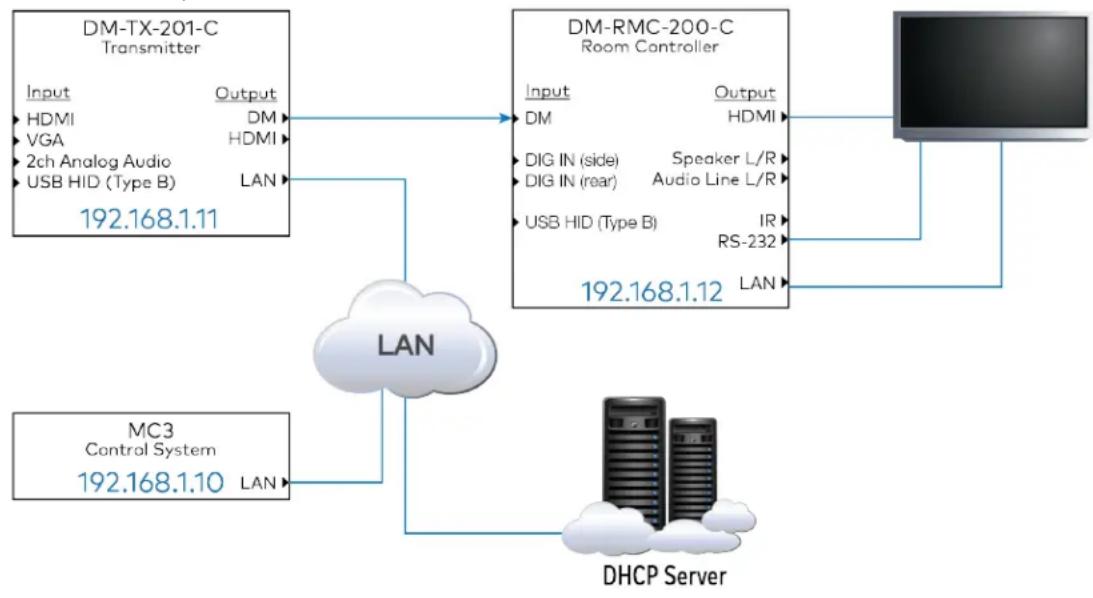
flowchart
graph TD
    A["DM-TX-201-C Transmitter"] -->|Input| B["DM"]
    A -->|Output| C["DM-RMC-200-C Room Controller"]
    B -->|LAN| D["DHCP Server"]
    C -->|LAN| D
    E["MC3 Control System"] -->|LAN| D
    F["Computer"] -->|LAN| D
    G["192.168.1.11"] --> A
    H["192.168.1.12"] --> C
    I["DIG IN (side) | Speaker L/R"]
    J["DIG IN (rear) | Audio Line L/R"]
    K["USB HID (Type B) | IR"]
    L["RS-232"] --> C
Switcher-basedSystem
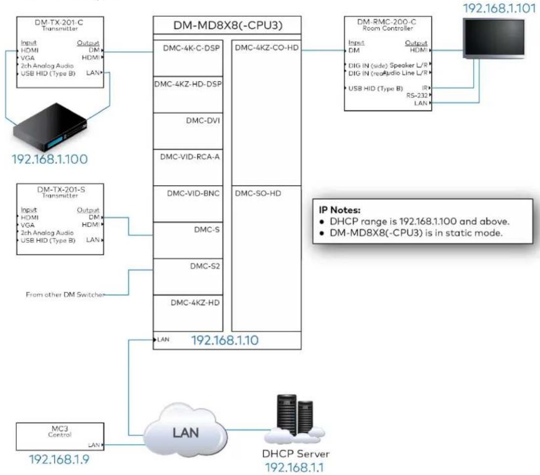
flowchart
graph TD
    A["192.168.1.100"] --> B["DM-TX-201-C Transmitter"]
    B --> C["Input: HDMI, VGA, 2ch Analog Audio, USB HID (Type B)"]
    B --> D["LAN"]
    E["192.168.1.101"] --> F["DM-RMC-200-C Room Controller"]
    F --> G["Input: DM, DIG IN (side), Audio Line L/R, RS-232, LAN"]
    F --> H["IP Notes: DHCP range is 192.168.1.100 and above. DM-MD8X8(-CPU3) is in static mode."]
    I["192.168.1.9"] --> J["MC3 Control"]
    J --> K["LAN"]
    K --> L["DHCP Server 192.168.1.1"]
    M["From other DM Switcher"] --> N["DM-TX-201-S Transmitter"]
    N --> O["Input: HDMI, VGA, 2ch Analog Audio, USB HID (Type B)"]
    N --> P["LAN"]
    Q["DM-MD8X8(-CPU3)"] --> R["DMC-4K-C-DSP"]
    Q --> S["DMC-4KZ-HD-DSP"]
    Q --> T["DMC-DVI"]
    Q --> U["DMC-VID-RCA-A"]
    Q --> V["DMC-VID-BNC"]
    Q --> W["DMC-S"]
    Q --> X["DMC-S2"]
    Q --> Y["DMC-4KZ-HD"]
    Q --> Z["LAN"]
    AA["192.168.1.10"] --> AB["DM-MD8X8(-CPU3)"]
    AB --> AC["DMC-4KZ-CO-HD"]
    AB --> AD["DMC-SO-HD"]
NOTE: Crestronhastreenewswitchers: DM-MD8X8-CPU3, DM-MD16X16-CPU3, and DM-MD32X32-CPU3 For simplicity throughout this document, the switchers are designated as DM-MD8X8(-CPU3), DM-16X16(-CPU3), and DM-MD32X32(-CPU3) to accommodate both the older and newer models.
DMroom controllers comefullyequippedwithanintegratedEthernetswitch.Aspare EthernetportisconnectedtoaDMswitcher.Thisportcanbeusedfor connectingother Ethernetdevices.Whenadevice(other thanaDMdevice)isconnectedtoaDMcourtesy port,theEthernetconnectionis passedtransparentlythroughtheDMnetworkasthough thatdeviceisconnecteddirectlytothepublicLAN. Inapoint-to-pointscenario,theEthernetportcanbeusedas anuplinktothemain network.For example,ifasystemcontains aDM-TX-200-C-2GTransmitter anda DM-RMC-100-CReceiver,theDMC-RMC-100-Cmustserveas theuplinkpoint,sincethe DM-TX-200-C-2Gdoes notprovideanEthernetport.IftheDM-TX-200-C-2Gisreplaced withaDM-TX-201-Cor DM-TX-401-C,theEthernetuplinkcanoccur ateither the transmitter or theroomcontrollersincebothof thesedevices haveanavailableEthernet port.
NOTES:
- Inpoint-to-pointsystems, only one of the devices should connect to them again network. Insystems with switchers, the switcher should be the only device connected to thenetwork. See Appendix B: DMCablePlant Certification.
- WithPNMenabled,theendpointcourtesyports mustnever beconnectedtothe publicLANtowhichtheDMswitcher isconnected.
- PNMis notconfigurableontheDMC-CPU3controller card,whereitis always enabled.
HD-DTDS Specification and DMCertified Training
Crestronprovides thedefinitivedesign,installation,andcommissioningspecificationto guaranteeethereliableperformanceof DigitalMediasystems.TheHD DigitalTransportand DistributionSystem (HD-DTDS)specificationandcorrespondingcourseworksetahigh benchmarkfor digitalAVsystems.Thespecificationestablishes anindustrystandard and theCMCertificationprogram ensures thatAVprofessionalsarefullyeducatedandadhere tothestandard.
HD-DTDS Specification
Toassurereliablesystemperformance,theHD-DTDSspecificationdefiphestecritical aspects of systemdesignandinstallation.Crestrongguarantees andfullysupportsanyDM systeminstallationthatconformstoHD-DTDSstandards.Designers, whousethisDM HD-DTDSspecificationguaranteetheir customers thatthedesignisfinalizedbyaDMC-E, ensuringproper systeminstallationandconfigurationof HDCP,video,resolution management,cabling,andcablingdistance.
DM CertifiedDesigner - 4K(DMC-D-4K)
In this free online course, the fundamental differences between analog and digital systems are covered, including the unique design considerations to ensure reliable system operation for a4K distributed system. The course concludes with an exam that must be passed to earn DMC-D-4K certification. DMC-D-4K is a prerequisite for the DMC-E-4K course.
DM CertifiedTechnician - 4K(DMC-T-4K)
This isahands-onclass for AVprofessionals who install systems or need a deeper understanding of installation requirements. Attendees are trained on all copper and fiber termination options available for DM systems and cable plant certification. Upon course completion, the attendees are able to install and test the performance capabilities of a DM system. The course concludes with practical exam that must be


passedtoearnaDMC-T-4Kcertification.Anonwaivable\$300 coursefeesrequired.
DM Certified Engineers - 4K(DMC-E-4K)
This rigorous 3-dayprogramincludes DMC-DandDMC-T Certification and details every aspect of system installation and commissioning. Only a DMC-E-4K is qualified to fully execute and support a DM project. ADMC-E-4K demonstrates proficiency in system setup, diagnostics, testing and reporting. Only Crestrondealers with a DMC-E-4K staff can bid on projects designed using the HD-DTDS if the attendee is a DMC certified Designer (DMC-D-4K), afreeonlinerefresher course must be completed in order to add DMC-E-4K certification credentials. Anonwaivable \$1,000 course fees is required.
Coursesfillupfast,soreserveaseattoday.Thereisalimitoftwopeopleper companyper class. For more information refer to the Crestron Technical Institute on the Crestron website.

Crestron 4K Certification Program
Toensurethatinstallationsrunsmoothly, Crestronhas introduceda4KCertification program. Under this program, manufacturers submit their 4Ksources and displaysto Crestron. Crestronensures that the 4Ksources and displays do the following:
- Deliver true10Gbits/s datarates togetthesignalto its destination
- Interface with DigitalMediatohandlecablelengths found in integrated AVsystems
• Workwithother 4Kproducts inaDigitalMedia system

Crestron4KCertification guaranteeesthatcertifiedsources anddisplays meetthe demands ofa4Kdistributedsystem.Crestronengineers intheDigitalMedialabrigorously test4Kproducts toensuretheyworkinamatrix-switchedenvironment.Onlythosethat doarewardedtheCrestron4KCertifiedlogo.
NOTE: For more information on 4K, see the 4K White Paper on the Crestron website.
InfrastructureChoices
With modular input and output cards, DM systems offer several different ways of transportings signals: H.264 Ethernet streaming, Digital Media 8G+ (Digital Media over a single CAT5 or better UTP or STP), and Digital Media 8G™ fiber (Digital Media over a single strand of multimode fiber).
NOTE:DM8G®andDM8G+®products are recommended for newinstallations.
CompareCopper and Fiber Transports
DigitalMediauses twistedpair andfiber cablingtotransportsignals.
Copper and Fiber Benefits
| Cable Type Maximum Distance Benefits | ||
| Copper Upto330 ft(100 m) | FamiliarReadilyavailablenexpensivePreexistinginfrastructure | |
| Fiber | Upto1000 ft(300 m) with multimode fiberUpto7.5miles (12 km) with single-mode fiber | LongtransmissiondistanceNotsusceptible toEMIArmoredjacketavailableExtremelyhighbandwidthEasy toterminate |
DigitalMediaTransportTechnologyTypes
| Technology Maximum Distance Cabling | Notes | ||
| DMUltraCable | Upto330 ft(100 m) | CAT7a | - |
| DM8G+ | Upto330 ft(100 m) | Single CAT5-type | Onlyupto 230 ft(70 m) for 4K |
| DM8G Fiber | Upto1000 ft(300 m) | Single strandof multimode fiber | - |
| DM 8G Single-mode Fiber | Upto7.5miles(12 km) | Single strandof single-mode fiber | Compatible onlywith single-mode .fiber .S2 hardware (Notcompatible with other DM8G fiberproducts) |
Copper Infrastructure
Theterm "copper"inaDigitalMediacontextrefers totwistedpair cable.WithDM,choose thecablebasedontheapplication.
DM 8G+ Performance over Copper
DM8G+transmitshigh-resolutiondigitalsignalsover unshieldedCAT5eUTPwithminimal errors.DM8G+technologymaintains signalintegrityover UTPwithoutusingcompression, makingiteasytoupgradeexistingQM,PVID,andother analogdistributionsystems while deliveringthehighestqualityHD videoandaudio,alongwithEthernet,USBHD,and control.For bestresults,Crestronrecommends usingshieldedDM8G+cable DM-CBL-ULTRA).

HDBT ^TM ASE
AllDM8G+products , arebasedonHDBaseT®technology,and allproducts arecertifiedbytheHDBaseTAlliance.This ensures the highest level of reliability and performance, and guarantees compatibility betweenDM8G+products and third-partyHDBase devices,suchas HDBase displays.
Shielded Infrastructure
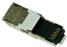
Tomaintainthewireshieldthroughouttheentirecablerun,besuretousefullyshielded components. Thewireshields renderedineffectivefitis notcarriedthroughthe connector.CrestronDM-CONN,DM-8G-CONN,DM-8G-CONN-WG,DM-RPP-K24,and DM-CBL-ULTRA-PCarefullyshieldedforusewithDigitalMedia.Inaddition,ifusingpatch points,besuretocarrytheshieldthroughhallconnectingpoints.Theseincludewallplates, batchpanels,andpatchcables.
DM-CONN DM-8G-CONN
natural_image
Close-up of a black and white electronic component with metallic pins (no visible text or symbols)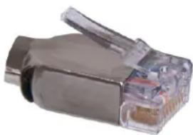
natural_image
Close-up of a gray metal USB connector with a transparent plastic tip (no text or symbols visible)DM-8G-CONN-WG
natural_image
Close-up of a blue network Ethernet cable with USB port (no text or symbols visible)DM-CONN-ULTRA-RECP
natural_image
Two gray and blue industrial Ethernet connectors with visible internal ports (no text or symbols)Copper Terminations and Patching
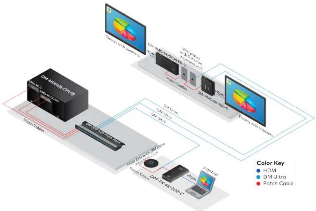
Crestronstrongly recommends using telecommunications industry-standardstructured cablingpractices as defined by EIA/TIA568 and ISO/IEC11801. The long-permalinkable that runs between devices should be determined with femalereceptacles (or jacks). Factory-terminated and certified patchcables should be used to connect device to the permalink run. This cabling method increases system reliability and allows scalable installations to be certified according to industry-standard test procedures.
According to these practices, permalink cableruns maybeupto295 ft(90m), and patch cablesupto16ft(5m) maybeusedoneachside, for anoverallchannellength of 328ft (100m). Besuretotakeintoconsiderationalcablebendradias defined by the cable manufacturer.
PatchingGuidelines
flowchart
graph TD
    A["Display with spewers"] --> B["DM-MDBX8-(CPU3)"]
    B --> C["DM-4K-C"]
    C --> D["DM-ax-CO-HD"]
    D --> E["Patch Cables"]
    E --> F["DM-RMC-4K-SCALER-C"]
    F --> G["DM-RMC-4K-100-C"]
    G --> H["DM Ultra"]
    H --> I["DM Ultra"]
    I --> J["DM Ultra"]
    J --> K["Floor box with DM Ultra"]
    K --> L["Patch Cable"]
    L --> M["DM-TX-4K-202-C"]
    M --> N["Laptop"]
    style A fill:#f9f,stroke:#333
    style B fill:#ccf,stroke:#333
    style C fill:#cfc,stroke:#333
    style D fill:#fcc,stroke:#333
    style E fill:#cff,stroke:#333
    style F fill:#ffc,stroke:#333
    style G fill:#cfc,stroke:#333
    style H fill:#cfc,stroke:#333
    style I fill:#cfc,stroke:#333
    style J fill:#cfc,stroke:#333
    style K fill:#cfc,stroke:#333
    style L fill:#cfc,stroke:#333
    style M fill:#cfc,stroke:#333
    style N fill:#cfc,stroke:#333
Crestronhasacompletelineofstructuredcablingaccessoriestosupportthesepractices:
. DM-CONN-ULTRA-RECPDigitalMediaUltraKeystoneRJ45 Jack
. DM-RPP-K24 DigitalMedia24-PortKeystonePatchCable
. DM-CBL-ULTRA-PCDigitalMediaUltraPatchCable
The accessories above are compatible with both DMUltra and DM8Gcabling.
NOTE: While stillofficially supported, field-terminated male connections and the use of male-to-male couplers arenolonger recommended.
Cable Types
The followingtable shows themaximum cablelengths bycabletype.
| Resolution | DigitalMedia Ultra Cable(DM-CBL-ULTRA) | DigitalMedia 8G Cable(DM-CBL-8G) | CAT5e (orbetter UTP or STP |
| 1080p60 FullHD 330 ft(100 m) 330 ft(100 m) 330 ft(100 m) | |||
| 1920 x 1200 WUXGA 330 ft(100 m) 330 ft(100 m) 330 ft(100 m) | |||
| 1600 x12 UXGA 330 ft(100 m) 330 ft(100 m) 330 ft(100 m) | |||
| 2048 x 1080 2KDCI 330 ft(100 m) 330 ft(100 m) 330 ft(100 m) | |||
| 2560 x1140 WQHD 330 ft(100 m) 230 ft(70 m) 165 ft(50 m) | |||
| 2560 x1600 WQXGA | 330 ft(100 m) 230 ft(70 m) 165 ft(50 m) | ||
| 3480 x 2160 Ultra HD | 330 ft(100 m) 230 ft(70 m) 165 ft(50 m) | ||
| 4096 x2160 4KDCI | 330 ft(100 m) 230 ft(70 m) 165 ft(50 m) | ||
Fiber Infrastructure
DM8G Fiber Comparison-8G Multimodevs. 8GSingle-Mode
| DM 8G Multimode FiberTechnology DM 8G Single-Mode Fiber Technology | ||
| Connector Details |  |  |
| Example Cable | ||
| Fiber Description | Single strand(simplex) of multimode fiber | Single strand(simplex) of single-mode fiber |
| Cable Requirements Crestron Third-party | CresFiber® 8G cable and CresFiber cable OM3* | CresFiber 8G-SM OS1or better |
| Connector Requirements | OneSC50 μmconnector per end OneLCconnectorper end | |
| Maximum Distance | 1000 ft(300 m)* 7.5miles (12 km) | |
| Benefits | OneterminationperendInexpensive fiber solutionCanuse existinginfrastructure | Extremelylongdistance transmissionOneterminationperendCanuse existinginfrastructure |
| Notes | Requiresonestrandofmultimode fiber, plus backsinthe eventof breakageCrestronrecommends pullingat leasttwostrands toeachlocation | Requiresonestrandofsingle-mode fiber, plus backupsin the eventof breakageCrestronrecommends pullingat leasttwostrands toeachlocation |
* Distance is limited to 500 ft (153 m) CresFiber and OM3 or better. CresFiber8G ensures maximum transmission distance of 1000 ft (300 m).
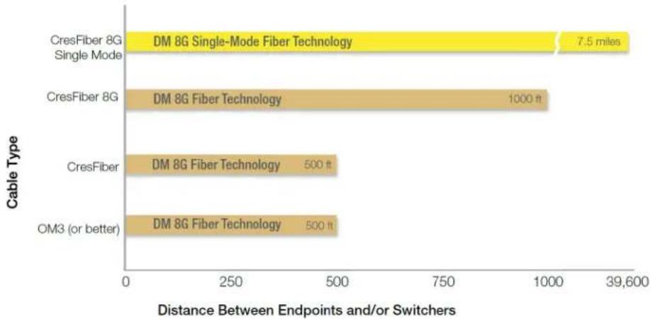
The following illustrations shows the maximum distance a DM fibers signal can run between endpoints and switchers at any resolution. An endpoint refers to any device, other than switcher, to which DM terminates from a transmitter or receiver. Because of the abundant bandwidth of fiber, video resolution does not affect transmission distance.
MaximumDMFiber TransmissionDistance
bar
| Cable Type | Distance Between Endpoints and/or Switchers | | :--- | :--- | | CresFiber 8G Single Mode | 7.5 miles | | CresFiber 8G | 1000 ft | | CresFiber | 500 ft | | OM3 (or better) | 500 ft |NOTE:CresFiber(CRESFIBER)is nolonger availableandhasbeenreplacedby CresFiber8G(CRESFIBER8G).
Fiber Cable Options
| Cable Model and Type DM 8G Multimode Fiber DM 8G Single-Mode Fiber | ||
| CresFiber 8G | 1000 ft(305 m) max distance | - |
| CresFiber 500 ft(153 m) maxdistance -OM3/OM4 (orbetter) 500 ft(153 m) maxdistance - | ||
| CresFiber 8G Single-Mode - | 7.5miles (12 km) max distance | |
| G.652.D (or better)Single-Mode - | 7.5miles (12 km) max distance | |
DM3DFacts
. MostDMdevices arereadytosendandreceive3Dvideo.
. 3D does notrequirebandwidthbeyondthatof a1080psignal.
. Consultindividualspecsheets for detailedcompatibilitywith3D.
DM8Gfibercanbepatchedthroughapanel,wallplate,or similar point.Usethefollowing guidelines:
- Anynumber of patchpoints maybe used as longastheentirefiber loss does not exceed 4dB.
- Anytypeof fiber connector maybeusedinpatches aslongas, thefiber that terminates attheDMdeviceusesSCconnectors (for DM8Gfiber) or LCconnectors (for DM8Gsingle-modefiber).
- For information on how to test for optical loss, see Appendix B: DM Cable Plant Certification.
Fiber Facts
. OM3andOM4 usuallyhaveanaqua-coloredjacket.
. OM3andOM4 haveacoreandcladdingdiameterof50/125μm.
- SCconnectors aremostcommonfor inside-planttelecom, but recently LC connectors (natively compatible only with DM8G single-mode products) are becoming more popular dueto their smaller size.
- Intermediatepatchpanels and connectionscanuseothertypes of connectors if necessary.
DigitalMediaand 4K
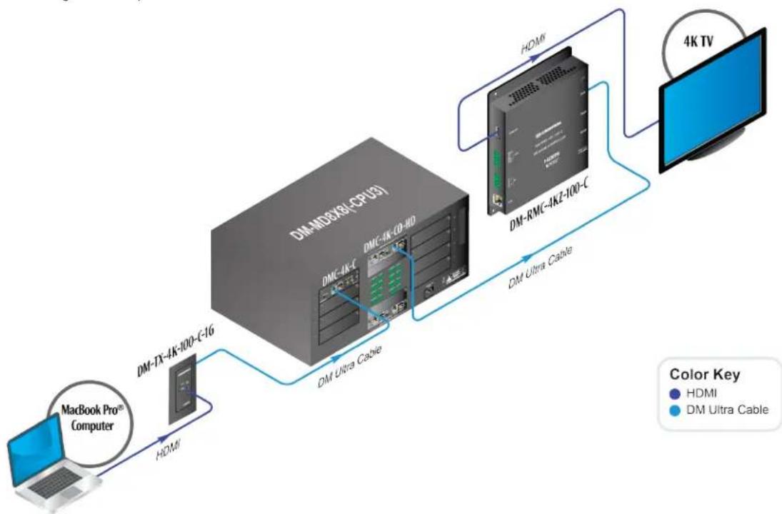
The following examples shows a working 4K application.
Working4KExample
flowchart
graph LR
    A["MacBook Pro™ Computer"] -->|HDMI| B["DM-TX-4K-100-C16"]
    B --> C["DM-CD/MDX80-CPU31"]
    C --> D["DM-RMC-4KZ-100-C"]
    D --> E["4K TV"]
    C -->|DM Ultra Cable| D
    style A fill:#f9f,stroke:#333
    style E fill:#bbf,stroke:#333
NOTE: For simplicity, patchpoints are not shown in the illustration above.
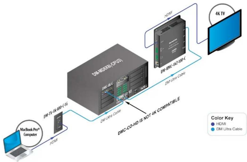
The following examples shows anonworking4Ksetup, TheDMC-CO-HD outputcard within theDM-MD8X8(-CPU3)switcheris not4Kcompatibleandthereforecannotprovide4K signals tothedisplay. Thesourcemustbesettooutput1080ptopass thesignaltothe display.
Nonworking4KExample
flowchart
graph LR
    A["MacBook Pro® Computer"] -->|HDMI| B["DM-TX-4K-100-C-16"]
    B --> C["DM-MDBX8(CPU3)"]
    C --> D["DM-RMC-4KZ-100-C"]
    D --> E["4K TV"]
    C -->|DM Ultra Cable| F["DM-CO-HD IS NOT 4K COMPATIBLE"]
    style A fill:#f9f,stroke:#333
    style B fill:#ccf,stroke:#333
    style C fill:#cfc,stroke:#333
    style D fill:#fcc,stroke:#333
    style E fill:#cff,stroke:#333
    style F fill:#ffc,stroke:#333
Select DigitalMediaEquipment
DigitalMedia Switchers
NOTE: Crestronhastreenewswitchers: DM-MD8X8-CPU3, DM-MD16X16-CPU3, and DM-MD32X32-CPU3. For simplicity, throughout this document, the switchers are designated as DM-MD8X8(-CPU3), DM-16X16(-CPU3), and DM-MD32X32(-CPU3) to accommodate both the older and newer models.
Therearefour maintypesof DMswitchers:
. Modular (card-based)
. Modular (blade-based)
. Fixed(cardless)
. DigitalMediaPresentationSystems (DMPS)
DigitalMedia Modular Switchers: Card-based
There are three Digital Mediaswitcher cardframes: DM-MD8X8(-CPU3), DM-MD16X16(-CPU3), and DM-MD32X32(-CPU3). Each switcher permits inputs to be cascaded with up to four additional switchers, increasing then number of available outputs in the system while maintaining HDCP compliance. For example, using five DM-MD16X16(-CPU3) switchers in asystem provides at total of 80 available outputs.
DMinputandoutputcarddetailsare:
- Inputandoutputcardsmustbeselectedattimeoforder.
. Switchers areshippedpre-loadedwithcustom configuration. - Inputandoutputcardsmaybeaddedandreconfiguredinthefield.
NOTE: DisplayPortMultimodeconnectivity is supported via an HDMI or DV input port using a suitable adapter or interfaceable (not included).
Whatis RPS?
DigitalMediaswitcher cardframes are available with a redundant powers supply, denoted by RPS at the end of them model name. With the RPS option, the unit continues to operate if one of the power supplies fails. The DM-MD8X8(-CPU3)-RPS, DM-MD16X16(-CPU3)-RPS, and DM-MD32X32(-CPU3)-RPShaveanMTBF (Mean Time Between Failures) of onemillion hours.
NOTE: RPSmodels donotprovideDMNet™ powerinternally. Instead, DMNetpower must be provided by external power supplies such as CNPWS-75 and C2N-SPWS300. DM8G+andDM8GFiberendpointsdonotrequireDMNetpower.
DM-MD8X8(-CPU3)andDM-MD8X8(-CPU3)-RPS
. 8inputcardslots(fieldupgradeable)for upto8AVsources
- 8DMroomoutputs and/or HDMIoutputs for upto40outputs using multiple chassis
. 4DMCoutputcards (fieldupgradeable)
• FullaudioandUSBbreakaway
- DM-MD8X8(-CPU3)-RPS has internal redundant power supplies for utmost reliability(MTBF of onemillion hours)
. 4K/4KZ*ready
DM-MD8X8-CPU3-RPS
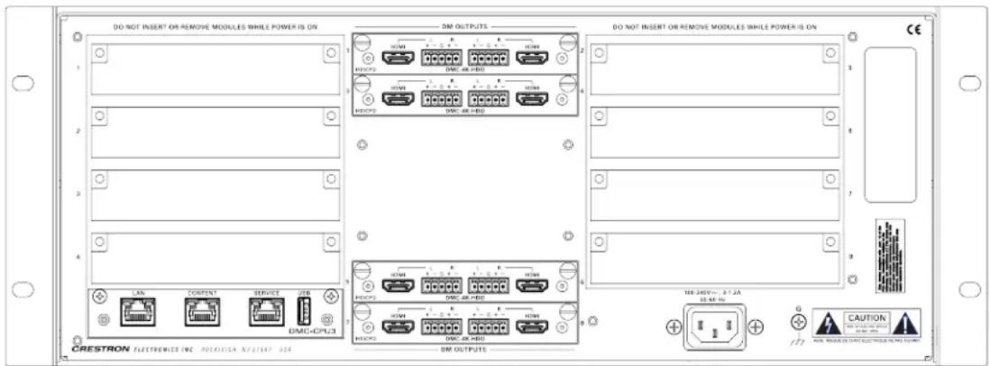
4K
* Crestronoffersa new set of DM 4KZcards and endpoints that enable new and existing DM systems to handle full 4K60 4:4:4 videosignals, as well as HDR video signals(HDR10), without having toreplace any wiring orswitchers. The term "4KZ" refersto 4K60 4:4:4 and HDR video signal support.
DM-MD16X16(-CPU3)andDM-MD16X16(-CPU3)-RPS
. 16inputcardslots(fieldupgradeable)for upto16AVsources
- 16DMroom outputs and/or HDMIoutputs for upto80outputsusingmultiple chassis
. 8DMCoutputcards(fieldupgradeable)
• FullaudioandUSBbreakaway
- DM-MD16X16(-CPU3)-RPShasinternalredundantpower suppliesfor utmost reliability(MTBF ofonemillionhours)
. 4K/4KZ*ready
DM-MD16X16-CPU3-RPS
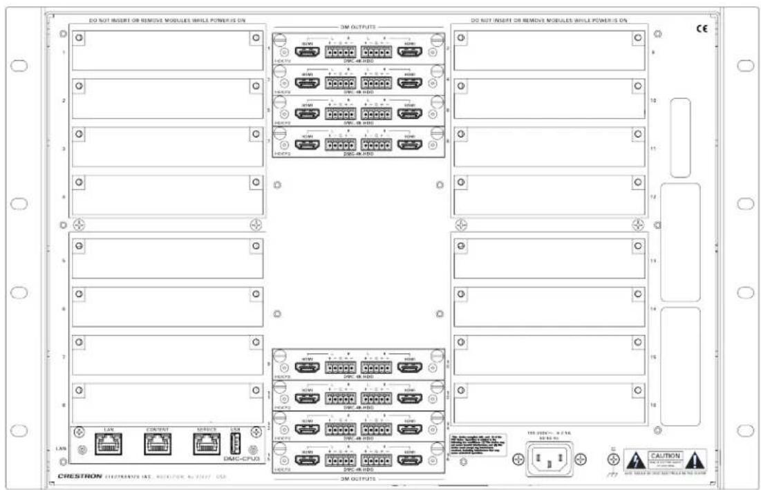
4K
* Crestron offers a new set of DM 4KZ cards and endpoints that enable new and existing DM systems to handle full 4K60 4:4:4 video signals, as well as HDR video signals(HDR10), without having to replace any wiring or switchers. The term "4KZ" refersto4K60 4:4:4 and HDR video signal support.
DM-MD32X32(-CPU3)andDM-MD32X32(-CPU3)-RPS
. 32inputcardclots(fieldupgradeablefor upto32AVsources)
. 32DMroomoutputs and/or HDMI outputs for upto160 outputs using multiple chassis
. 16DMCoutputcards (fieldupgradeable)
• FullaudioandUSBbreakaway
- DM-MD32X32(-CPU3)-RPShas internalredundantpowersupplies for utmost reliability(MTBFofonemillionhours)
. 4K/4KZ*ready
DM-MD32X32-CPU3-RPS
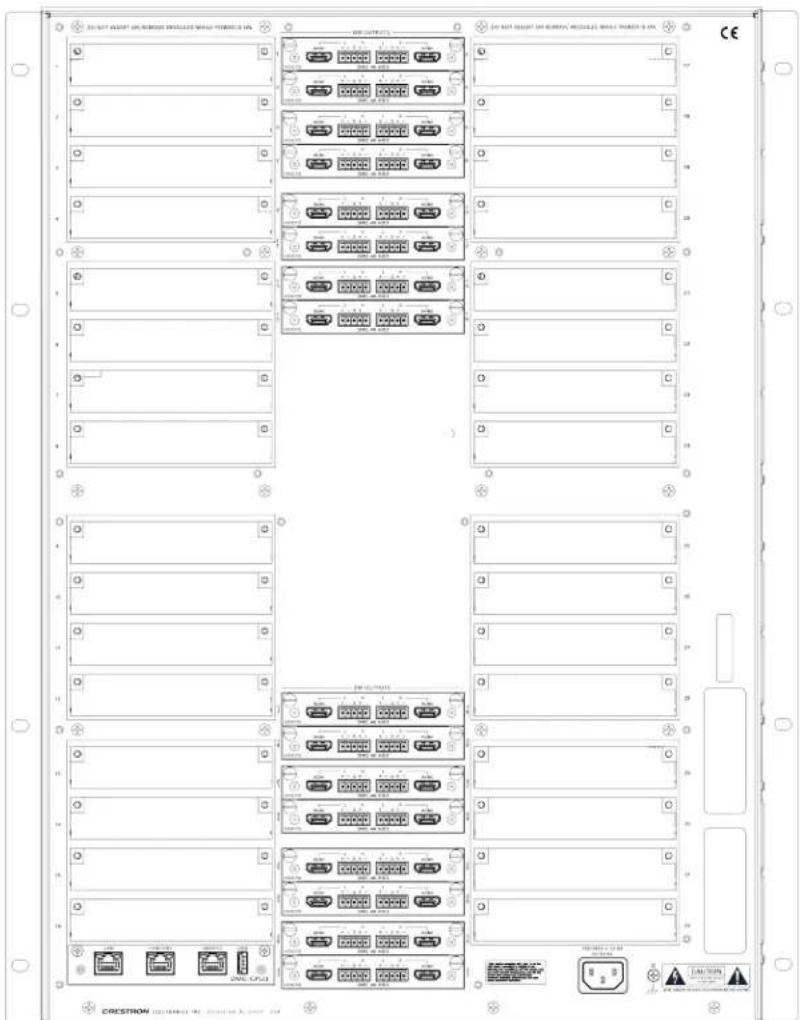
4K
* Crestron offers a new set of DM 4KZ cards and endpoint that enable new and existing DM systemsto handle full 4K60 4:4:4 video signals, as well as HDR video signals (HDR10), without having to replace any wiring or switchers. The term "4KZ" refer to 4K60 4:4:4 and HDR video signal support.
DigitalMedia Switcher InputCards:Local Sources
AllinputcardsprovideanHDMIloopoutputfor switcher expansion.
DMC-4KZ-HD
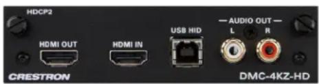
TheDMC-4KZ-HD includes4KZ*HDMIinput, RCAanalogaudiooutput(whichbreaks outthe embeddedHDMI audiotofeedamultiroom, audio distributionsystem),andUSBHID port(which passes aremotemouseor keyboardsignaltothe sourcedevice).
* Crestron offers a new set of DM 4KZ cards and endpoints that enable new and existing DM systems to handle full 4K60 4:4:4 video signals, as well as HDRvideo signals (HDR10), without having to replace any wiring or switchers. The term "4KZ" refers to 4K60 4:4:4 and HDR video signal support.
Additionalmodelsareshownbelow.
| Model Description Notes | ||
| DMC-4KZ-HD | HDMIInputwith4KZ Support Includes USBHID | |
| DMC-4KZ-DSP | ||
| DMC-VID-RCA-D | RCA AnalogVideoInputCardwith S/PDIF Audio | YPbPr,Y/C, composite |
| DMC-VID-RCA-A | RCA AnalogVideoInputCardwith AnalogAudio | YPbPr,Y/C, composite |
| DMC-VID-BNC | BNCAnalogVideo InputCard | YPbPr,Y/C, composite, balanced audio |
| DMC-VID4 | QuadVideo InputCard | Composite video, for viewing securitycameras |
| DMC-DVI | DVI/RGBInputCard | Analoganddigital video input, analogaudio,supports USBHID |
| DMC-SDI | SDIInputCard | Supports SD-SDI,HD-SDI, and 3G-SDI |
| DMC-VGA | VGA orAnalogVideo InputCard | YPbPr,Y/C, composite |
For acompleteinputcardlist,seewww.crestron.com/digitalmedia.
DigitalMediaSwitcher InputCards: RemoteSources
DMC-4KZ-C-DSP
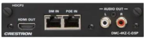
TheDMC-4KZ-C-DSPDMsignalis ,receivedfrom aDM8G+transmitter theoutputofanother DMswitcher or anHDBaseT ^TM certifiedsource viaqsingleCATtypetwistedpair cable. The built-inDSP processingendblessimultaneous multichannel7.1surroundand2-channelstereo signals.
DMC-STR
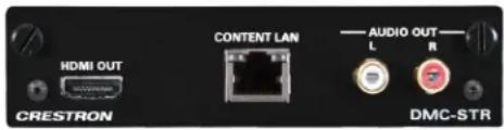
TheDMC-STRprovides onestreaminginputthat receives asingleH.264 videostreamoveran IP networkfrom anotherDMswitcher,anIP camera,astreamingserver,or aCaptureHD® system.
Additionalmodels areshownbelow.
| Model Description Notes | ||
| DMC-4KZ-CDMC-4KZ-C-DSP | DM8G+ InputCardwith4KZ | Compatible withDM-TX-201-CDM-TX-200-C-2G, DM-TX-401-C,DM-TX-4K-100-C-1G,DM-TX-4K-202, DM-TX-4K-302,DM-TX-4KZ-202-C,andDM-TX-4KZ-302-CFor applicationsrequiringsupportfor higher resolutions upto4K |
| DMC-CDMC-C-DSP | DM8G+ InputCardwithOptionalDown-Mixing | Compatible withDM-TX-201-C,DM-TX-200-C-2G, andDM-TX-401-CFor use withsurroundsoundsources |
| DMC-SDMC-S-DSP | DM8G Fiber InputCardwithOptional Down-Mixing | DSP versionadds DSP for7.1-channel down-mixing |
| DMC-S2DMC-S2-DSP | DM8G Single-Mode Fiber InputCardwithDown-Mixing | DSP versionadds DSP for7.1-channel down-mixing |
| DMC-STR H.264 | StreamingInputCard | Upto25 Mbps RTSPStreamDecoder |
For acompleteinputcardlist,seewww.crestron.com/digitalmedia.
DigitalMedia Switcher OutputCards
Crestronoffers acompleteselectionofoutputcardsfor DigitalMediamatrixswitchers to allownumerous combinations of DigitalMedia,HDBaseT,HDMI,H.264 streaming,and analogaudiooutputs onasingleswitcherchassis.
- TheDM-MD8X8(-CPU3)canhold4DMCoutputcards.TheDM-MD8X8(-CPU3) holdsupto2outputspercardfor atotalof8possibleoutputs.
- TheDM-MD16X16(-CPU3)canhold8DMCoutputcards.TheDM-MD16X16(-CPU3) holdsupto2outputspercardfor atotalof16 possibleoutputs.
- TheDM-MD32X32(-CPU3)canhold16DMCoutputcards.TheDM-MD32X32(-CPU3) holdsupto2outputspercardfor atotalof32possibleoutputs.
Someof theavailableDMoutputcardsareshownbelow.
DMC-4KZ-CO-HD
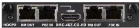
2-ChannelHDBaseTCertified4KZ*DigitalMedia 8G+OutputCardfor DMSwitchers
DMC-4K-HDO

2-Channel4KScalingHDMIOutputCardfor DM Switchers

DMC-HDO

2-ChannelHDMI OutputCardfor DMSwitchers
DMC-SO-HD

2-ChannelDigitalMedia8GFiber OutputCard for DMSwitchers
DMC-S2O-HD

2-ChannelDigitalMedia8GSingle-ModeFiber OutputCarafor DMSwitchers
DMC-STRO

StreamingOutputCardfor DMSwitchers
* Crestron offers a new set of DM 4KZ cards and endpoint that enable new and existing DM systemsto handle full 4K60 4:4:4 videosignals, as well as HDR videosignals (HDR10), without having to replace any wiring or switchers. The term "4KZ" refersto4K60 4:4:4 and HDR video signal support. ADMSwitcherConfigurationToolisavailabletoassistwithDMswitcher setup.
DigitalMediaModular Switchers: Blade-based
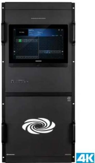
TheDM-MD64X64 andDM-MD128X128featureCrestronbladearchitecturewith high-densityandhigh-reliabilityfeatures suchas:
• Hot-swappablepowersupplies, I/Oblades, and fantray
. Field-replaceableCPUandfrontpanel
. Maximumreliabilityanduptime
. Designadas corebuildingor campus-widerouter
DM-MD64X64
. 8inputbladeslots(hot-swappable)
. 8outputbladeslots (hot-swappable)
. Upto64 outputs
. FullUSBbreakaway
. 14-space19-inchrack-mountable
- Two-power supplies (onerequired for operations) for utmost reliability
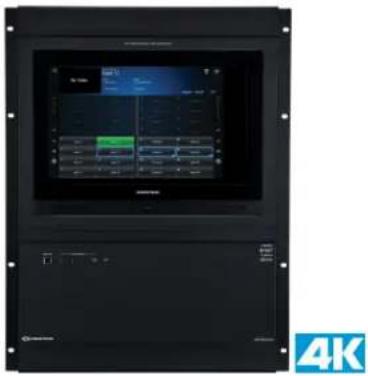
DM-MD128X128
. 16inputbladeslots (hot-swappable)
. 16outputbladeslots (hot-swappable)
. Upto128outputs
• FullUSBbreakawayUSB HID Switch
. 24-space19-inchrack-mountable
- Twopower supplies (onerequired for operations) for utmost reliability
natural_image
Black server rack with digital display and spiral logo, no visible text or symbols on main componentsDigitalMedia Switcher InputBlades
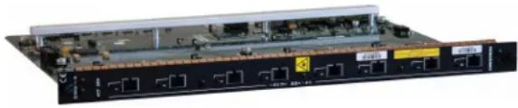
EachinputbladeprovideseightDMor HDMIinputchannels totheDM-MD64X64 or DM-MD128X128backplaneswitch.
DMC-I-S
natural_image
Front view of a network switch device with multiple ports and connectors (no visible text or labels)TheDMB-I-Sincludes eightDM8G Fiber inputs, each of which receives a DMsignal from a DM8GFiber transmitter or another DMswitcher. For a complete input card list, see www.crestron.com/digitalmedia.
Additionalmodels areshownbelow.
| Model Description Notes | |||
| DMB-4K-I-HD HDMIInputx8 with 4KSupport | Includes AnalogAudioInput x8 | 4K | |
| DMB-4K-I-HD-DNT | HDMIInputx8 with 4Kand DanteTM Support | Includes AnalogAudioInput x8 | 4K |
| DMB-I-S DigitalMedia8G Fiber Inputx8 | Compatible with DM-TX-201-Sand DM-TX-401-S | ||
| DMB-I-S2 | DigitalMedia8G Single-Mode Fiber Inputx8 | Compatible with DM-TX-201-S2 and DM-TX-401-S2 | |
| DMC-4K-I-C DigitalMedia8G+Inputx8 | Compatible with DM-TX-201-C, DM-TX-200-C-2G, DM-TX-401-C, DM-TX-4K-100-C-1G, DM-TX-4K-202-C, DM-TX-4K-302-C, DM-TX-4KZ-202-C, and DM-TX-4KZ-302-C | 4K | |
DigitalMediaSwitcher OutputBlades
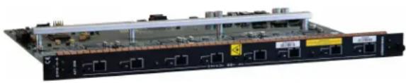
DMC-O-S
natural_image
Front view of a network equipment rack with multiple ports and connectors (no visible text or labels)TheDMB-O-S includes eightDM8G Fiber outputs, each of which transmits a DM signal to a DM8GFiber receiver or another DM switcher. For a complete output card list, see www.crestron.com/digitalmedia.
Additionalmodels areshownbelow.
Model Description Notes
| DMB-4K-O-HD | HDMIOutputx8 with4K Support | Includes AnalogAudio Outputx8 |  |
| DMB-4K-O-HD-DNT | HDMIOutputx8 with4K andDante Support | Includes AnalogAudio Outputx8 |  |
| DMB-O-S | DigitalMedia8G Fiber Outputx8 | Compatible withDM-RMC-100-S, DM-RMC-150-S, DM-RMC-200-S, and DM-RMC-SCALER-S | |
| DMB-O-S2 | DigitalMedia8G Single-Mode Fiber Outputx8 | Compatible with DM-RMC-200-S2 | |
| DMC-4K-O-C | DigitalMedia8G+ Outputx8 | Compatible withDM-RMC-200-C, DM-RMC-4K-100-C-1G, DM-RMC-SCALER-C, DM-RMC-4K-100-C, DM-RMC-4K-SCALER-C, and DM-RMC-4K-SCALER-C-DSP |  |
DigitalMedia FixedSwitchers
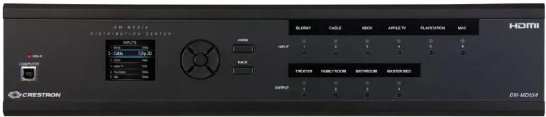
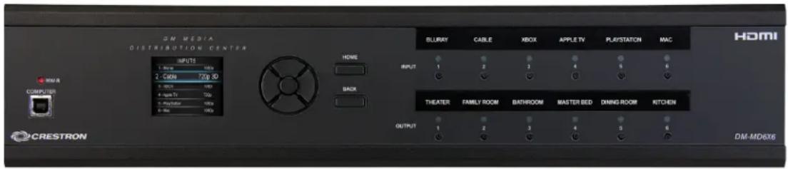
CrestronDMfixedswitchers provideasimpleandcost-effectivesolutionfor distributing multiplehigh-definitionAVsources touptosixrooms.DMswitchers_areintendedtobe usedinsmaller applications thatdonotrequireexpansion.TheDMfixedswitchers are availablein6x4 and6x6matrices.
- DM-MD6X4 capabilities: sixHDMI inputs, threeDM8G+outputs, and oneHDMI output
- DM-MD6X6 capabilities: sixHDMI inputs, fiveDM8G+outputs, and oneHDMI output
DM-MD6X4
DM-MD6X6
AboutUSBHID
USBHID isaUSBdeviceclass usedfor interfacedevicessuchasmiceandkeyboards. USBHID features astandardcommunications interfacethatallows devices to communicatewithoutspecialdrivers.Althoughcommunicationflows bothways,the importantcommandflowofkeyboardstrokes,mouseoutput,etc.goes from ,the device tothehost.ThesquaretypeBconnector ontheDMinputcardsis consideredahost portbecauseitconnectstothehost,andtheDMroom controller has,arectangular typeAdeviceporttoconnecttoUSBHID devices.For moreinformationonUSBdevices supportedbyDigitalMediaseeCrestronTrueBlueOnlineHelpAnswer ID 5007.
DigitalMedia4KFixedSwitchers
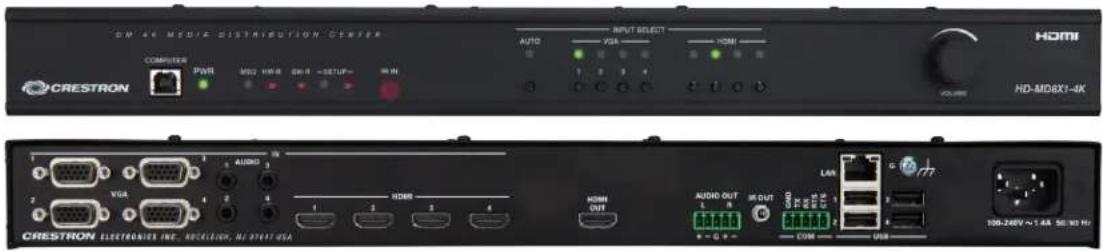
TheHD-MD8X1-4KandDM-MD8X1-4K-Careultrahigh-definitionscalingpresentation switchers withadvancedfeatures thatarebestsuitedfor huddlerooms,conference rooms,andclassrooms. Theyintegratemultiformatauto-switcher,4Kvideoscaler,audio DSP,andcontrolinterface,allintoonecompactdevicethatmounts,convenientlyundera tableor inanequipmenttrack.Built-inCrestronConnectIt™ functionalityaffords a completecollaborationsolutionthat's easyandaffordabletodeployinanymeetingspace.
. HD-MD8X1-4Kcapabilities:four VGAinputs and four HDMI outputs
- DM-MD8X1-4K-Ccapabilities:four VGA inputs,four HDMI outputs,oneDMoutput,andoneMicinput
HD-MD8X1-4K(FrontandRear)

DM-MD8X1-4K-C(FrontandRear)
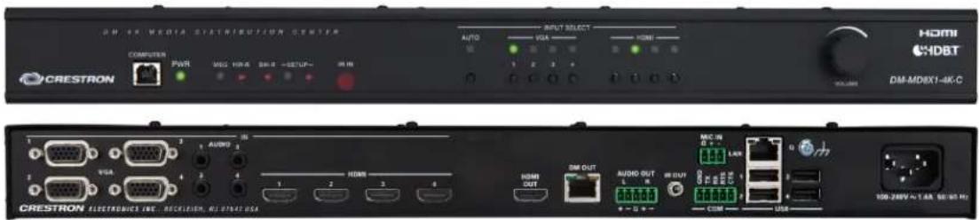

For application examples using DM switchers, see Appendix C: Application Diagrams. For more information on the HD-MD8X1-4K and DM-MD8X1-4K-C switchers, see the Software Features of the DM-MD8X1-4K-Cand HD-MD8X1-4K Operations Guide (Doc. 7772) on the Crestron website.
DMPS PresentationSystems
TheDMPSis, apowerful3-Series® controlprocessor, thatprovidesacomplete, high-definitionpresentationcontrolandsignalroutingsolutionfor boardrooms,lecture nails,andvideoconferencerooms.MorethdnanAVcontrolprocessor,theCrestron 3-Series isanintegratedbuildingmanagementplatform capableofunifyingthevarious technologieswithinacommercialbuildingtooperateas,asingleintelligentsystemrather thaninsils as separatesystems.DMPSmodelsincludetheDMPS3-4K-50, DMPS3-4K-100-C,DMPS3-4K-150-C,DMPS3-200-C,DMPS3-4K-250-C,DMPS3-300-C, DMPS3-4K-350-C,andDMPS3-300-C-AEC.TheDMPS3-300-C-AECis anenhanced versionoftheDMPSfeaturingfull-bandwidthacousticechocancellation.
ThesearepreloadedwithDMPS3.AVFramework™ softwarethatdoes allthe programmingfor you,enablingcontrolof asingledisplaydevice,integrationwith AirMedia®presentationgateway,andcentralizedmonitoringthroughCrestronFusion® software.
Withoutrequiringaseparatecontrolsystemor anyprogramming,theDMPSmodelsare easilyconfigurablefor avarietyofmediapresentationapplications andarecompatible withatouch screen,iPad®device,or computer for setupandcontrol.
• DMPS3-4K-50: four HDMI inputs, four VGA inputs, and one HDMI output
- DMPS3-4K-100-C: four HDMI inputs, four VGA inputs, one HDMI output, and one powered DMoutput
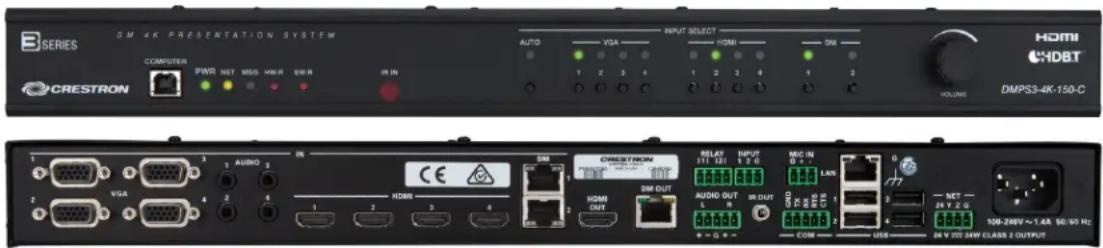
- DMPS3-4K-150-C: four HDMI inputs, two DM inputs, four VGA inputs, one HDMI output, and onepowered DM output
- DMPS3-200-C: five HDMI inputs, one powered DM input, three VGA inputs, one HDMI output, and twopowered DM outputs
- DMPS3-4K-250-C: six HDMI inputs, one powered DM input, one HDMI output, and onepoweredDMoutput
- DMPS3-300-C: five HDMI inputs, two powered DM inputs, three VGA inputs, two HDMI outputs, and twopowered DM outputs
- DMPS3-4K-350-C: six HDMI inputs, two powered DM inputs, two HDMI outputs, and twopoweredDMOutputs
- DMPS3-300-C-AEC: five HDMI inputs, two powered DM inputs, three VGA inputs, twoHDMloutputs,andtwopoweredDMloutputs
DMPS3-4K-150-C(FrontandRear)
AcontrolsurfacecaneasilybeaddedtotheDMPS3-4K-350-C,whichallows presenters to turnthesystem onandoff,selectasource,andadjustthevolumeusingaCrestrontouch screen,buttonpanel,computer,or iPad.Thecompletesystemconfigurationis enabled rightfromthedevicesothattheinstaller canquicklyselectthecontrolsurface,specifythe displaydevice.andassignuser-friendlynames andiconstotheinputsandoutput.The preloadedDMPS3.AVFrameworksoftwareenablescustomizedpresentationcontrol withoutprogramming.
Aninstantswitchingsystem can be created by connecting up to four Crestron ConnectIt TT-100 cablecaddies. Thesourceslection buttons and feedback work as soon as the USB cables are connected. Meetingor class participants simply connect their laptops with the Crestron Connect It device at the table or lectern, and then press the Show Me button to immediately display their content. The DPMS3-4K-150-C can control any Crestron Connected display or projector via Ethernet, any flat panel with HDMICDC, and many popular displays via RS-232.
For moreinformation on.AVFramework,seethe.AVFrameworkSoftwarefor DMPS3 Operations Guide(Doc.7887)ontheCrestronwebsite.
DMPS3-300-C (FrontandRear)
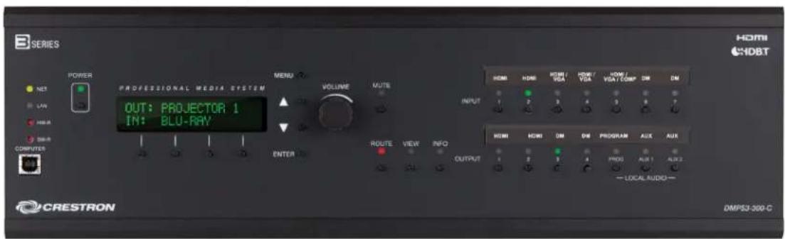
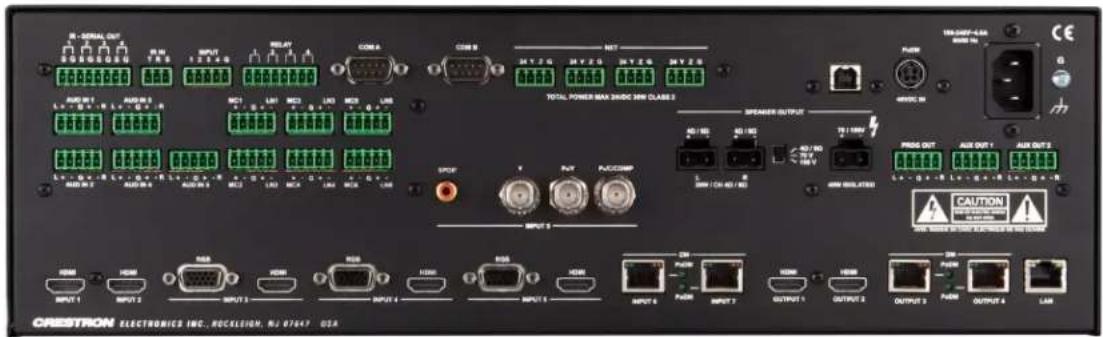
TheDMPS3-300-Cintegrates thecontrolsystem,multimediamatrixswitcher,micmixer, audioDSP, amplifier, and DigitalMediadistributioncenter qllintoasing13-spacerack-mountablepackage, TheDMPS3-300-Caffordssubstantialsignal-routingflexibilityand high-performancesignalprocessingwithouttheneedfor separatecomponents. The preloadedDMPS3.AVFrameworksoftwareenablescustomizedconfigurationandcontrol withoutprogramming.
DMPS3-300-C-AEC(FrontandRear)
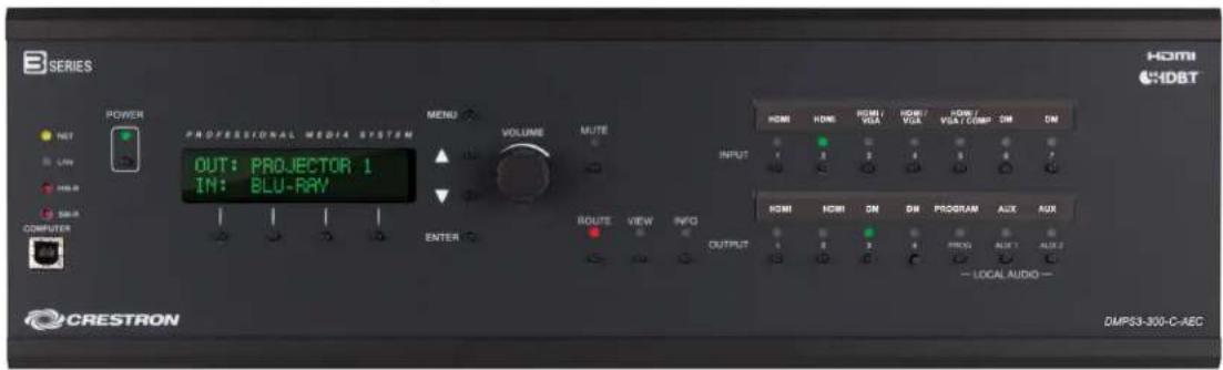
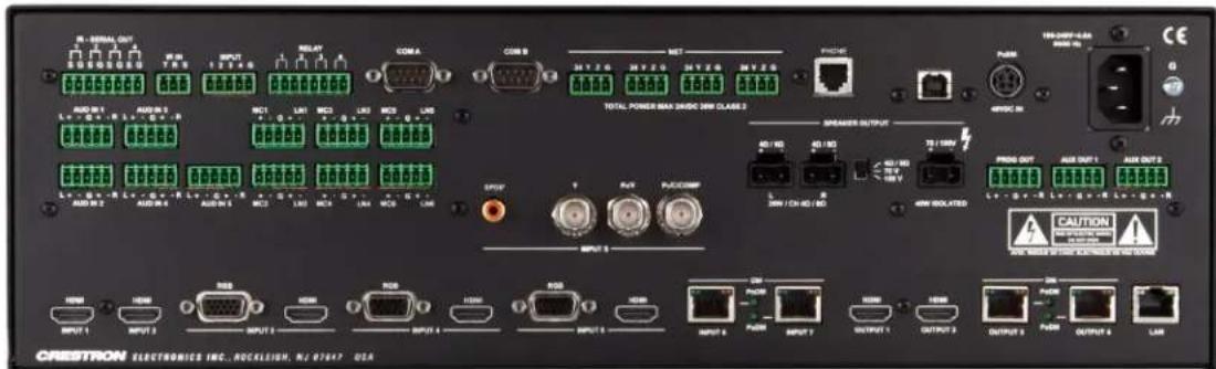
TheDMPS3-300-C-AECprovides acompletepresentationcontrolandsignal-routing solutionwithbuilt-inaudioconferencingfor boardrooms, andclassrooms.Integratingthe controlsystem,multimediamatrixswitcher,micmixer,audioDSP,amplifier,and DigitalMediadistributioncenterallintoasingle3-spacerack-mountablepackage,the DMPS3-300-C-AECaffords substantialsignal-routingflexibilityandhigh-performance signalprocessingwithouttheneedfor separatecomponents. Its built-inaudio conferencinginterfaceandfull-bandwidthacousticechocancellationalallowfor high-quality,full-duplexvoiceconferencingviaanSIP or POTSline,andseamless integrationwithuptotwoexternalvideoconferencingcodecs.
DigitalMedia Room Controllers
Roomcontrollers provide the connection between the DM signal and output devices such as display. All room controllers feature low profile design and can be installed behind flat panel displays and above ceiling-mounted projectors.
DM-RMC-4K-SCALER-C
natural_image
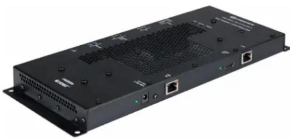
Exterior view of a black network switch device with ports and ventilation slots (no visible text or symbols)4K
TheDM-RMC-4K-SCALER-Cprovidesa controller and interface for an HD or 4K display device as part of a complete Digital Mediasystem. It includes a built-in 4K/60 scalar and analog audio output. It easily connects to the DM 8G+ output of a DM switcher or transmittervia CAT5e, DM8G, or DM Ultra Cable. This controller is compatible with HDBaseT and includes IR, RS-232, Ethernet, and relay control ports.
Thetables onthefollowingpages listthefeatures for differentmodels. FeatureComparisonChart(1of2)
| DM-RMC-SCALER-C DM-RMC-200-C DM-RMC-100-S DM-RMC-150-S | DM-RMC-SCALER-S (-S2) | |||||
| DMCommunication | DM 8G+ DM 8G+ DM 8G Fiber DM 8G Fiber | DM 8G Fiber(-S)DM 8G Single-Mode Fiber (-S2) | ||||
| VideoOutput Types | HDMI orDVI | HDMI orDVI | HDMI orDVI | HDMI orDVI | HDMI orDVI | |
| Video Scaler | 2K | 2K | - | - | 2K | |
| AudioOutput Types | HDMI | HDMI, Analog stereo | HDMI | HDMI, Analog stereo | HDMI | |
| Stereo Amplifier | - | 30 W | - | - | - | |
| IR Ports | 2 | 2 | 2 | 2 | 2 | |
| COM Ports | 1 | 1 | 1 | 1 | 1 | |
| Ethernet | Yes | Yes | Yes | Yes | Yes | |
| Power Supply | Included | Included | Included | Included | Included | |
| USB Port | Yes | Yes | - | Yes | Yes | |
| Relays | - | 2 | - | 2 | - | |
| Contact Sensing Input | - | 1 | - | 1 | - | |
| Mounting | 2-gang wall box | 2-gang wall box | Surface mount | Surface mount | 2-gang wall box | |
| Power over DM | - | - | - | - | - | |
FeatureComparisonChart(2of2)
| DM-RMC-200-S(-S2) DM-RMC-4KZ-100-C DM-RMC-4K-100-C-1G DM-RMC-4K-SCALER-C | ||||
| DMCommunication | DM 8G Fiber (-S)DM 8G Single-ModeFiber(-S2) | DM 8G+ | DM 8G+ DM 8G+4K | 4K |
| Video OutputTypes | HDMI or DVI HDMI or DVI HDMI or DVI HDMI or DVI | |||
| Video Scaler 2K - - 4K/60 | ||||
| Audio OutputTypes | HDMI,Analog stereo | HDMI | HDMI | HDMI,Analog stereo |
| Stereo Amplifier | 30 W | - | - | - |
| IR Ports | 2 | 2 | 1 | 2 |
| COM Ports | 1 | 1 1 1 | ||
| Ethernet | Yes Yes | - Yes | ||
| Power Supply | Included | Included | Included | Included |
| USB Port | Yes - - - | |||
| Relays | 2 | - - 2 | ||
| Contact SensingInput | 1 | - - - | ||
| Mounting | 2-gangwall box | Surfacemount | 1-gang wall box and surface mount | Surfacemount |
| Power over DM | - | Yes | Yes | Yes |
For a more information on DM room controllers and receivers, see www.crestron.com/digitalmedia.
DigitalMedia HD Streaming Receiver and Room Controller
DM-RMC-100-STR
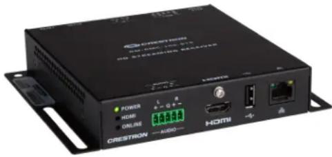
TheDM-RMC-100-STRis acompactH.264 streamingdecoderdesignedtoreceive high-definitionAVsignals over an IP network,Itisaperfectcomplementto anyDigitalMediaswitcherwithstreaming outputandcanalsobeseadoadd streaminginputcapabilitytoother switchers'ahddevices.
DigitalMedia HD Streaming Transmitter and Receiver
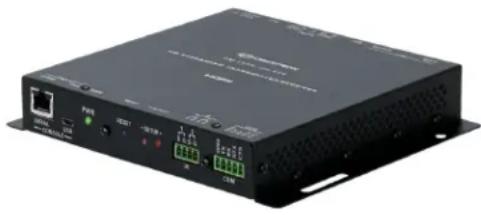
DM-TXRX-100-STR
natural_image
Black industrial electronic device with ports and indicator lights (no visible text or symbols)TheDM-TXRX-100-STRisacompactH.264 streamingencoder and decoder designed to enabled distribution of high-definition AV signals over anIP network. It is configurable a either a transmitter or receiver and a perfect complement to any Digital Media switcher with one or more streaming inputs or outputs. The DM-TXRX-100-STRcan also be used to add streaming capability to other switchers and devices.
DigitalMedia Transmitters
DMtransmitters provide the ability to add remotes resources to the switcher system via CAT5e, DMcableor fiber. DMtransmitters are typically used in conjunction with modular DMswitchers and DMPS models, but the also working in point-to-points systems with DM room controllers and receivers.
DM-TX-201-C(FrontandRear)
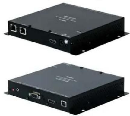
• Built-in2x1.AVswitcher withauto-switchingand analogaudiobreakaway
- Connects to Digital Mediaswitcher or receiver via CATSeor better cable
. HDMIandRBG/componentvideoinputs
. USBtypeBHID deviceport
- Low-profile, surface-mountdesign
- LocalHDMImonitor output
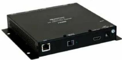
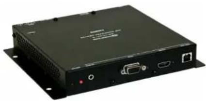
DM-TX-201-S(FrontandRear)
natural_image
Black electronic device with ports and ventilation slots (no visible text or symbols)• Built-in2x1.AVswitcher withauto-switchingand analogaudiobreakaway
- Connects toDigitalMediaswitcheror receiver via onemultimoderiber strand
. HDMIandRBG/componentvideoinputs
. USBHID deviceportfor connection toa computer
- Low-profile, surface-mountdesign
. LocalHDMImonitor output
natural_image
Black electronic device with ports and ventilation slots (no visible text or symbols)DM-TX-201-S2
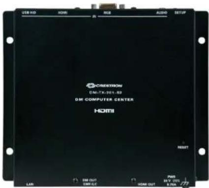
DigitalMedia8Gsingle-modefiber transmitter and multimedial interface
• Built-in2x1.AVswitcher withauto-switchingand analogaudiobreakaway
. HDMIändRBG/componentvideoinputs
. USBtypeBHID deviceport
. USBHD deviceportfor connection toa computer
- Low-profile, surface-mountdesign
- LocalHDMImonitor output
DM-TX-200-C-2G
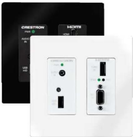
- DigitalMedia8G+ transmitter andmultimedia interface
• Built-in2x1AVswitcherwithauto-switchingand analogaudiobreakaway
. HDMI andRBG/componentvideoinputs - Connects toaDMswitcheror receiver viaone CAT5eor CrestronDM8Gcable
. Supports HDBaseTAlliancespecifications
DM-TX-4K-202-C
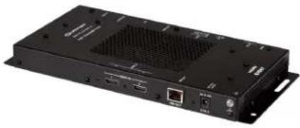
natural_image
Black electronic device with ventilation grille and ports (no visible text or symbols). 4KDigitalMedia8G+transmitter andmultimedia interface
. Built-in2x1 AVswitcher withauto-switching
- QuickSwitchHD technologyfor fast,reliable switching
- Connects toqDMswitcheror receiver viaone CA1typetwistedpair cable
- HDBase TCertified and enables direct connection to other HDBase I-certified equipment
DM-TX-4KZ-202-C
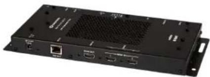
natural_image
Black electronic device rear panel with ports and ventilation grille (no visible text or symbols). 4KZDigitalMedia8G+transmitter and multimedialinterface
. Built-in2x1 AVswitcher withauto-switching
- QuickSwitchHD technologyfor fast,reliable switching
- Connects toqDMswitcheror receiver viaone CA1typetwistedpair cable
- HDBaseTCertified and enables direct connection to other HDBase1-certified equipment
DM-TX-4K-302-C
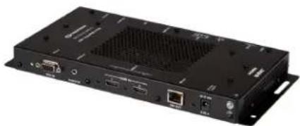
natural_image
Black electronic device with ventilation grille and ports (no visible text or symbols). 4KDigitalMedia8G+transmitter andmultimedia interface
• Built-in3x1,AVswitcher withauto-switchingand analogaudiobreakaway
- Connects toaDMswitcheror receiver viaone CATypetwistedpair cable
- HDBaseTCertifiedandenablesdirectconnection
toother HDBase1-certifiedequipment
DM-TX-4KZ-302-C
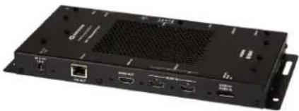
natural_image
Front view of a black electronic device with ports and ventilation grille (no visible text or symbols)- 4KZDigitalMedia8G+transmitter and multimediainterface
• Built-in3x1,AVswitcher withauto-switchingand analogaudiobreakaway - Connects toaDMswitcher or receiver viaone CATypetwistedpair cable
- HDBaseT Certified and enables direct connection to other HDBase1-certified equipment
DMTransmitters by Supporting Infrastructure
| Transmitter DM 8G+ DM 8G Fiber | DM 8G Single-mode Fiber | |
| 1-GangWall Box4K HDMITransmitter | DM-TX1-4K-C-1GDM-TX-4K-100-C-1G | |
| 2x1VGA, andHDMI Transmitter | DM-TX-201-C DM-TX-201-S DM-TX-201-S2 | |
| 2-GangWall Box VGA andHDMI Transmitter | DM-TX-200-C-2G | |
| 4x1VGA, HDMI, DisplayPort,and Composite Transmitter | DM-TX-401-C DM-TX-401-S DM-TX-401-S2 | |
| 4KTransmitter | DM-TX-4K-202-CDM-TX-4K-302-C | |
| 4KZTransmitter | BM-TX-4KZ-302-C | |
HDMI Solutions
The following HDMI solutions are compatible with Digital Mediaproducts. For more information on HDMI, see Appendix D: An In-depth Look at HDMI.
HDMI Switchers
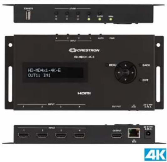
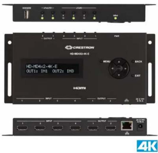
QuickSwitchHDswitchers from Crestronenablehigh-performanceHDMIsignalselection withnewfeaturesdesignedbyCrestrontodeliver trouble-free,low-latencyswitchingof, all DVD andBlu-ray®Discplayers,HDTVreceivers,mediaservers,gameconsoles,multimedia computers,surroundprocessors,andhigh-definitiondisplays.TheHD-MD4X1-4K-Eand HD-MD4X2-4K-Emodels featurefour HDMI inputsandasingleHDMIoutputtofeeda videodisplayorprocessor.TheHD-MD6X2-4K-Eoffers six HDMI inputs andtwo independentHDMI outputs.
HD-MD4X1-4K-E HD-MD4X2-4K-E
HD-MD6X2-4K-E(FrontandRear)
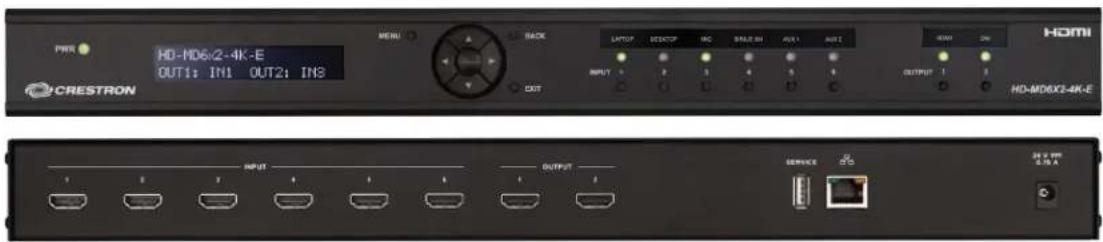

Somefeatures of theHDMI switchers:
- For stand-alone use or aspart of a fully-integrated Crestronsystem
- Fullyoperableusingfrontpanelcontrols, aWebbrowser, or aCrestroncontrol system
- Simplifiedsetupthroughthefrontpanel OLEDdisplayorWebbrowser
- Single-space19-inchrack-mountable design
-
Universal100-240Vexternalpower pack included
-
QuickSwitchHD technologymanages HDCPkeys forfast, reliableswitching
- Comprehensivebuilt-inEDID configurationtools
- DVlandDisplayPortMultimode compatible
- Handles DolbyTrueHD, DTS-HD Master Audio, and uncompressed 7.1 linear PCM audio
- High-speedEthernetLAN connection
HDMI Over Fiber Extenders
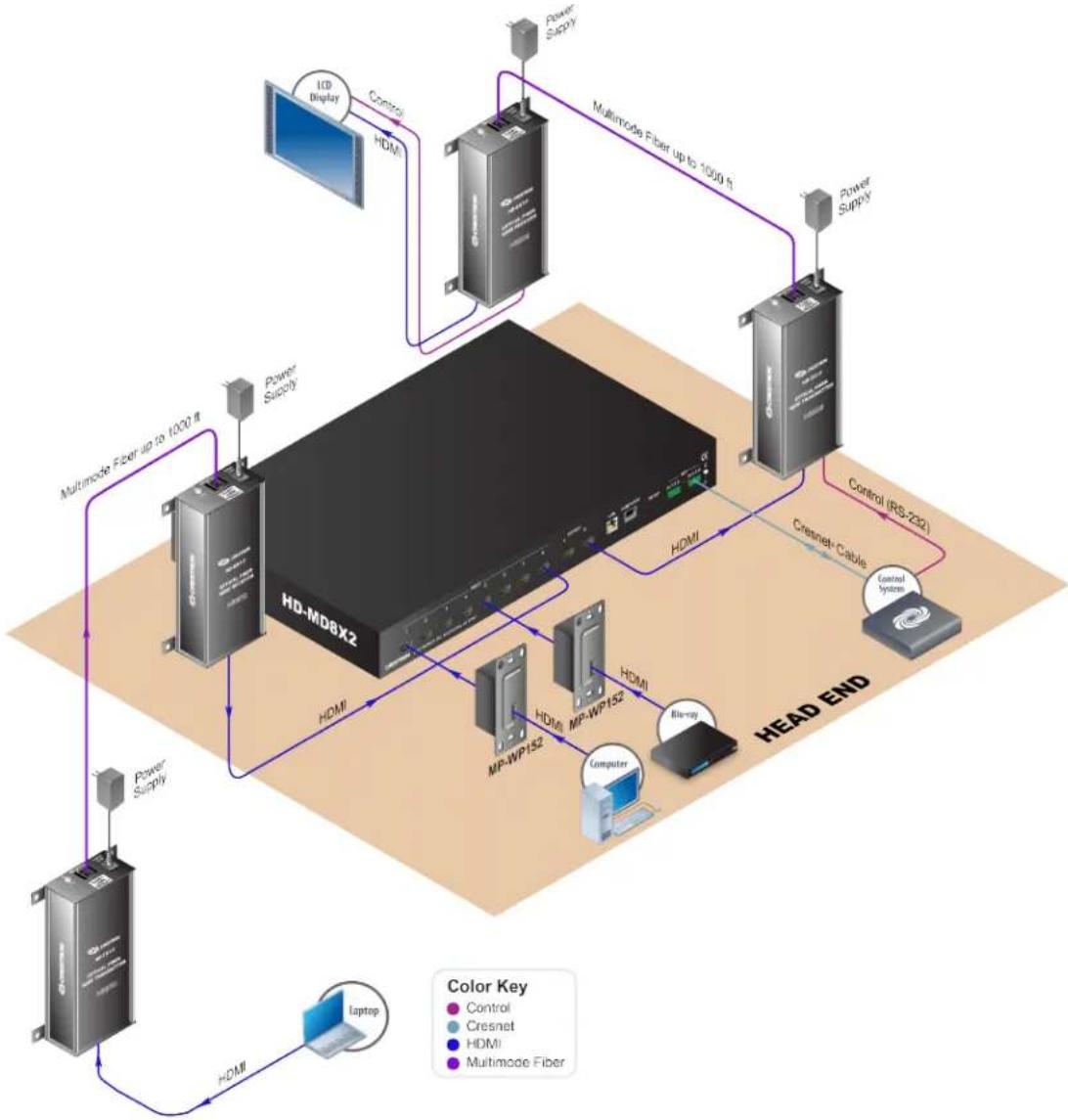
CrestronHDMIover Fiber Transmitters and Receivers deliver straightforward, cost-effective digital AVsignalextension for use in the home classroom, or corporate boardroom. The extenders enable wireruns upto 1000ft (300m) using just as single multimodefibercable. (For. MMOPTICALfiber wiring, use CRESFIBER-SINGLE-SCor other quality simplex multimodefiberopticcable.)
• Extends uncompressed digital video audio and controls signals, upto 100ft (300m) overasing iemultimoderiber
. Supports 7.1 lossless audioupto48kHz
- CompatiblewithDVIandDisplayPort Multimode
- Handles resolutions upto1920x1200 and 1080p60
. PassesEDID,CEC,andHDCP
. UniversallRrepeater upto192kHz
- BidirectionalRS-232extender upto115 kBd
- Noprogrammingor configuration needed
- TX3/RX3adds analogaudio,USBHID, andEthernetextending
HD-RX1-F (FrontandRear) HD-TX1-F (FrontandRear)

natural_image
Four black industrial electronic devices with ports and connectors, shown from different angles (no visible text or labels)HD-RX3-F (FrontandRear) HD-TX3-F (FrontandRear)

natural_image
Four black industrial electronic devices with ports and connectors, shown from different angles (no visible text or labels)HD-TX1-F and HD-RX1-F Application
flowchart
graph TD
    A["HD-MDBX2"] -->|HDMI| B["Power Supply"]
    A -->|HDMI| C["MC"]
    A -->|HDMI| D["MP-WP152"]
    A -->|HDMI| E["Blu-ray"]
    A -->|HDMI| F["Computer"]
    A -->|HDMI| G["Laptop"]
    H["ICP Display"] --> I["Control"]
    I --> J["HDMI"]
    K["Multimode Fiber up to 1000 fi"] --> L["Power Supply"]
    L --> M["HDMI"]
    N["Power Supply"] --> O["Control (RS-232)"]
    O --> P["Cresnet Cable"]
    P --> Q["Control System"]
    Q --> R["HEAD END"]
    S["Color Key"] --> T["Control"]
    S --> U["Cresnet"]
    S --> V["HDMI"]
    S --> W["Multimode Fiber"]
HDMIOver Copper Extenders
HD-EXT3-C
TheCrestronHDMlover_HDBaseT Extender(HD-EXT3-C)delivers professional-gradedigitalHDAVsignal extensionfor useinthethome,classroom, auditorium,or corporateboardroom. Withoutspecialsetupor configuration,the HD-EXT3-Cenables transmissionof high-definitiondigitalvideoandaudio,plus RS-232andRcontrol.
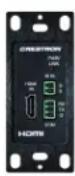
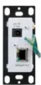
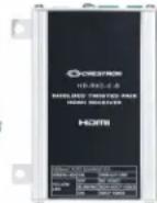
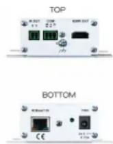
. HDBaseTCertified4KUltraHDsignalextender
- Extendsuncompresseddigitalvideo,audio,andcontrolsignalsoverasingleCATtype twistedpair cable
• Supports cablelengths upto330ft(100m) for all resolutions upto4KandUltraHD using qDMUltracable
• Supports cablelengths upto330ft(100m)for 1080p,WUXGA,and2KusingDM8G cableor CAT5e
• Supports cablelengths upto230ft(70m)for 4KandUHD usingDM8Gcable,or 165 ft(50m)usingCAT5e
. CompatiblewithHDMI,DVI,andDisplayPortMultimodesources
. CompatiblewithHDMI andDVIdisplaydevices
• Supports DolbyTrueHD,DTS-HD,anduncompressed7.1 linear PCMaudio
. HDCPcompliantandpasses CECandEDID
. Includes universallRepeater upto455 kHz
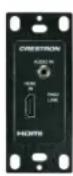
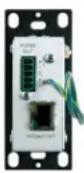
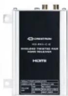
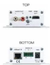
HD-EXT4-C
The Crestron HDMlover, HDBaseT Extender (HD-EXT4-C) delivers professional-graded digital HD AV signal extension for use in the home, classroom, auditorium, or corporate boardroom. Without special setup for configuration, the HD-EXT4-C enables transmission of high-definition digital video and audio.
. Handles4KUltraHD videoresolutions
. Supports HDBaseTAlliancecertifiedspecifications
• CompatiblewithHDMI,DVI,andDisplayPortMultimodesources
. HandlesFullHD 1080pvideoand3D
. Works reliablywithoutanyprogrammingor configuration
. PassesCEC,EDID andHDCP
. Includes universallRepeater upto455 kHz
HD VideoScalers
HD-SCALER-HD-E
HD-SCALER-HD-E
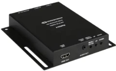
TheHD-SCALER-HD-Eis qsimple, cost-effective videoscaler designed to enable an HD, SD, or computer display device to handle virtually any input resolution up to Full HD 1080 por WUXGA. Its low-profile surface-mountable design and set-and-forgetsimplicity allow the HD-SCALER-HD-E. to be installed discreetly in the back of an equipment track, behind a flat panel display, or above aceiling projector. This scalar also includes stereo analog audio input and audio output for easy embedding to extract from HDMI.
HD-SCALER-VGA-E
HD-SCALER-VGA-E
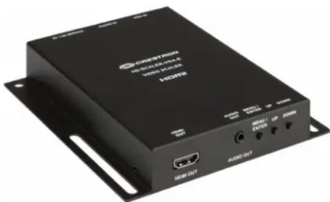
natural_image
Exterior view of a black H200 network device with ports and connectors (no readable text or symbols beyond branding)TheHD-SCALER-VGA-Eis,asimple, cost-effectivevideoscalerdesignedto enableanHD,SD,or,computer,display deviceohandleanalogVGA,RGB,and componentvideosignalswithinput resolutions uptoFullHD 1080por WUXGA. Its low-profile,surface-mountabledesign andset-and-forgetsimplicityallowthe HD-SCALER-VGA-Etobeinstalled discreetlyinthebackof anequipmentrack, behindaflatpaneldisplay,or aboveaceiling projector.Thisscaleralsoincludes stereo andlogaudioinputandaudiooutputfor easyembeddingtoorextractingfrom HDMI.
HDMIDistribution Amplifiers
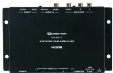
HD-DA-2
TheHD-DA-2is acompactwall- or rack-mountable1-to-2HDMI distributionamplifier. With the HD-DA-2, the audio portion of an HDMI signal can be added or extracted directly. The HD-DA-2 splits an HDMI signal into video for the display and audio for the surround soundprocessor. The audio is available in both S/PDIF (coaxial) and analog forms. The HD-DA-2 does not reverse, merging S/PDIF (coaxial or optical) and with an HDMI video signal into two HDMI outputs. In addition, the HD-DA-2 splits one HDMI input into two HDMI outputs.
. Provides a1-in,2-outHDMIsignalsplitter
• Supports7.1linear PCMor high-bitrateencoded audio
• Includes frontpanelinputsignalandHDCPstatus indicators
- EnablesextractinganalogandS/PDIFaudio signalsfrom theHDMI source
- Enable embedding and logandS/PDIF audio (coaxor optical) in the HDMI outputs
- Creates anHDMI signalfrom separatevideoand audio(S/PDIF)sources
4K
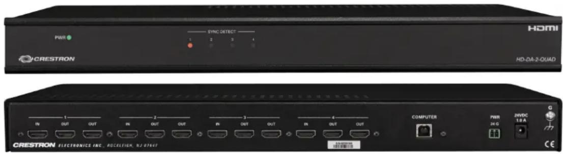
HD-DA-2-QUAD
TheHD-DA-2-QUADprovides four independent1-to-2HDMIdistributionamplifiers in a single rack-space unit, EDID and HDCP management is built into the device. Common uses are to split four HDMI sources and to expand the output of an HD-MD8X2.
• Providesfour independentHDMI splitters
- Enables audioloop-throughfor DVPHD inputs
- Handles3D and7.1 linear PCMor high-bitrateencodedaudio
. PassesEDID,CEC,andHDCP
- CompatiblewithDVIandDisplayPort
Multimode
• Single-space19-inchrack-mountable
• ControlsHDCPdigitalrights managementfor connecteddevices
• Performs automatic AV signal format management via EDID
- Includes external power supply
- Noprogrammingor controlsystem required
HD-DA-2-QUAD (FrontandRear)
HD-DA2-4KZ-E (also HD-DA4-4KZ-E and HD-DA8-4KZ-E)
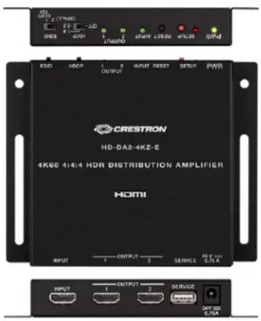
The HD-DA2-4KZ-Eis asimpletouse, high-performance 4KAV distribution amplifier designed to split single HDMI signal to feed two separate displays, switchers and/or other devices. It provides full support for UHD and DCI 4K604:4:4 and HDR video, HDCP 1.4 or 2.2 copy protection, and high-bit rate 7.1 audio, to ensure optimal performance and compatibility for any HD or 4K video application.
- Providesa1-in,2-outHDMIsignalsplitter
. Handles4K604:4:4andHDRvideosignals
• FullycompatiblewithHD1080p,UHD4K,andDCI 4Ksourcesanddisplays
. Handles3DvideoandDeepColor - Handles DolbyTrueHD, DolbyAtmos ^ , DTSHD ^ , DTS:X ^ , and uncompressed7.1 linear PCMaudio
. EDID managementoptions
. Noprogrammingorcontrolsystemrequired
HDMICables
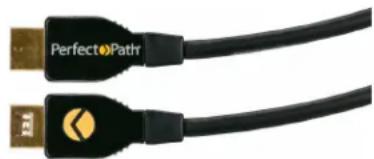
CBL-HD-LOCK
This premiumHDMI cableprovidesaperfectconnectionfor HD devices. ThePerfectPath® high-speedHDMI cablewithaPerfectLock™ lockingconnector keeps thecablesecurely lockedwhenpluggedintoanyTypeAreceptacle,butitiseasilydisengagedbypullingthe connectorbody.
• High-speedHDMI certified
• PerfectLockconnector with25lb.(34 kg) retention
. CL2/FT4 ratedfor in-walluse
• Supports3K,4K,andaudioreturnchannel
. Availableinavarietyof lengths
natural_image
Two USB cables with 'PerfectoPath' branding, no visible text or symbols on the cables themselves.4K
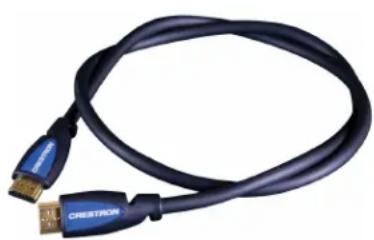
CBL-HD
High-quality, high-speed HDMI digital AV interface cables for connecting high-definition multimedia devices, such as DVD and Blu-ray Disc players, cable and satellite HDTV receivers, high-def video displays and projectors, surrounds sound processors, game consoles, and multimedia computers.
• High-speedCategory2HDMI cable
. Supports 1080p60HDTVwith16-bitcolordepth
. Supports 4K/604:4:4video@upto20ft(6.1 m)
. Handles computer resolutions uptoWQXGA
• Supports SACD, DVD-Audio, Dolby TrueHD, and DTS-HDMaster Audio
- 24karatgold-plated19-pinTypeAconnectors and high-flex CL3-ratedjacket
. Availableinavarietyoflengths
natural_image
Coiled black USB cable with blue connector, no visible text or symbolsUltra Cables, 8G Cables, and Accessories
DM-CBL-ULTRA-NP and DM-CBL-ULTRA-P
DM-CBL-ULTRAisahigh-bandwidthCAT7ashieldedtwistedpair(S/FTP)cable. Thiscable isengineeredtodeliver optimum. performance for 10GBdatanetworkingand4Kultra high-definitionAVsignaldistributionapplications.DM-CBL-ULTRAis available in plenum-ratedor riser-ratedtypes.
- ExceedsHDMI specificationsrequiringless than onepixelerror per billion
• Everyspoolindividuallytestedandcertified
• Measurementmarkings onouter jacket
• Available intypeCMR-rated for risérandother non-plenum installation, and CMP-rated for plenum installation

DM-CBL-8G-NP and DM-CBL-8G-P
CrestronDigitalMedia8Gcableisa350MHz-certifiedtwisted-pair cablewithoverallfoil shield(F/UFP)engineeredtodeliver optimum performancefor useindatanetworkingand high-definitionAvsignaldistributionapplications.DM-CBL-8Gisavailableinplenum-rated or riser-ratedtypes.
• Manufactured and tested to exceed CAT5e specifications and qualified for use wherever high-quality shielded CAT5e is required
- EnsuresCrestrongguaranteedperformancefor DigitalMedia8G+andSonnex®Link
• Highlyrecommendedfor usewithHDBaseT
. Spools individuallytestedandcertified
• Available intype CMR-rated for riser and other non-plenum installation, and CMP-rated for plenum installation

PatchCable, PatchPanel, and Receptacle
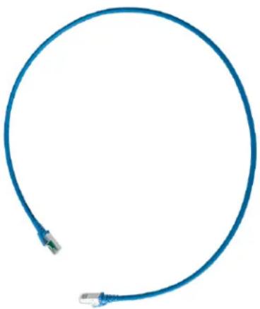
DM-CBL-ULTRA-PC
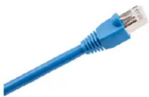
DM-CBL-ULTRA-PCis ashieldedCAT6apatchcabledesignedfor usewithallCrestron DigitalMedia8G+products as wellas HDBaseTand10GBase-TEthernet.Using DM-CBL-ULTRA-PCincombinationwithother CrestronDMUltrastructuredcabling products ensurestheighestperformanceandreliabilityfor distributingEthernetdata anduncompressed4K/60video.
- UniquePCB-basedRJ45 plugdesign
. 360degreeshieldcoverage - Low-profileandsnag-resistantbootdesignwithrobuststrainandbendrelief
. Cantileveredlatchfor enhancedaccessibility
• High-performanceCAT7S/FTPstrandedcable
. Aliéncrosstalkpreventiveconstruction
natural_image
Blue cable with two connectors, no text or symbols visibleDM-RPP-K24
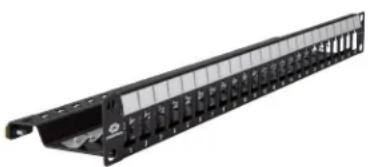
TheDigitalMedia24-PortKeystonePatchPanel(DM-RPP-K24)provides an enterprise-gradenetworkroutingsolutiondesignedinaccordancewithEIA/TIA specificationsfor useaspartofacompleteDM,HDBasel,or Ethernetinfrastructure.
. ShieldedCAT6aRJ45 jackssoldseparately
- Designed for 10GBase-TEthernet,CrestronDM 8G+,andHDBaseT
- CompatiblewithCrestronDM8GandDMUltra cable
. Field-terminable
- Individualrear cabletiepoints
. Versatilegroundlugplacement
. Single-space19-in.rack-mountable
natural_image
Black hard-shell network interface panel with multiple slots and mounting holes (no visible text or symbols)DM-CONN-ULTRA-RECP
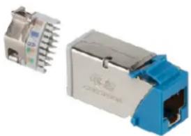
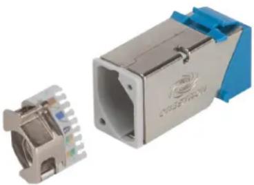
DM-CONN-ULTRA-RECPisashieldedCAT6aRJ45_jackdesignedforusewiththeCrestron DigitalMedia24-PortKeystonePatchPanel(DM-RPP-K24)or_anykeystonewallplace.It fitsinastandardkeystonemoduleopeningandcanbefield-terminatedinas littleas 60 seconds usingthetoolprovided.
• ExceedsCategory6Aperformancerequirements
. Ultra-fastandreliabletermination
• Enhanced360degreeshielding
. Accommodates multiplecablediameters
- CompatiblewithCrestronDM8GandDMUltra cable
- Soldinpacks of 20or 50withterminationtool included
natural_image
Two electronic connectors with metallic and blue plastic housing, one showing internal structure (no text or symbols visible)DigitalMedia4K/60 Fiber DistributionSystem
The Crestron Digital Media 4K/60 fiber distributionsystem provides 4K/60 video fiber distances. Thesystem includes 4K fiber transmitters and receivers that use SFP+ (Small Form-factor, Pluggable Plus) transceiver modules. Themodules support multimode and single-mode fiber.
The transmitters and receivers are available as stand-alone endpoints (DMF-TX-4K-SFP and DMF-RMC-4K-SFP) and as cards (DMCF-TX-4K-SFP and DMCF-RX-4K-SFP). An 8-cqrd slotchassis (DMF-CI-8) is designed to accommodate and power the DMCF series cards.
TheDigitalMedia4K/60fibersystem providesthefollowingfeaturesandbenefits:
. FullDM4K/60signalsupport
. ITindustry-standardfibersupport
. Singlesolutionadds fiberacrossproductlines
• Flexibilitytoadapttochangesinfiber typewithouthardwareswap
. End-to-endHDCP2support
For moreinformationontheDM4K/60fiberdistributionsystem,seetheDMF andDMCF Series:DigitalMedia4K/60Fiber DistributionSystem ReferenceGuide(Doc.7948)onthe Crestronwebsite.
DigitalMedia 4K/60Fiber Products
Themaincomponents of a4K/60fiber distributionsystem are:
• Fiber transmitter (DMF-TX-4K-SFPstand-aloneendpointor DMCF-TX-4K-SFP card)
- Fiber receiver (DMF-RMC-4K-SFP stand-alone endpointor DMCF-RX-4K-SFP card)
• Fiber cardchassis(DMF-CI-8)
- SFP+transceiver module(SFP-10G-SR,SFP-10G-BX-U,or SFP-10G-BX-D for new installations andSFP-10G-S-Uor SFP-10G-S-Dfor existingCresFiber 8G installations)
Fiber Transmitters
The fiber transmitter is available into physical configurations: the DMF-TX-4K-SFP stand-alone endpoint and the DMCF-TX-4K-SFP card.
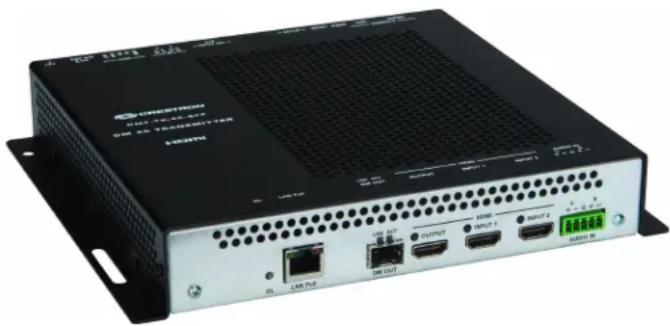
DMF-TX-4K-SFPTransmitter
TheDMF-TX-4K-SFPisafiber-basedtransmitterusedwithacompanionreceiver (DMF-RMC-4K-SFP or DMCF-RX-4K-SFP)tosupportpoint-to-pointsignalextension, andmayalsobeusedtoadd4Kfiber inputcapabilitytoaDigitalMediaswitcher. TheDMF-TX-4K-SFPincludes twoHDMIinputs for connectionof HD and4Ksources. SwitchingbetweentheHDMIinputs canbeperformedautomaticallyusingautoswitching mode, manually using the onboard INPUT SEL (select) button, or through programming viaaCrestroncontrolsystem.ThelocalHDMIoutputallows theselectedvideoandaudio inputsignals tobefedtoalocaldisplayor monitor.
NOTE: The DMF-TX-4K-SFP is sold as part of akitthatin includes one SFP+transceiver module.
DMF-TX-4K-SFP
natural_image
Exterior view of a black industrial network device with ports and connectors (no readable text or symbols)DMCF-TX-4K-SFPTransmitter Card
TheDMCF-TX-4K-SFPis afiber-based,transmitter, carddesigned,tofunctionas partofa Crestron4Kvideosignalextender solution,Itis usedwithacompanionreceiver (DMF-RMC-4K-SFPor DMCF-RX-4K-SFP)tosupportpoint-to-pointsignalextension, andmayalsobeusedtoadd4Kfiber inputcapabilitytoaDigitalMediaswitcher. TheDMCF-TX-4K-SFPinstalls inanyslotof aDMF-CI-8cardchassis.TheDMOUTport allows for theinsertionof anappropriateSFP+transceiver moduletoenablecompatibility withmultimodeor single-modefiber.ItalsofeaturetwoHDMI inputs oneanalogaudio input,alocalHDMI output,andaGigabitEthernetLAN port.TheDMCF-TX-4K-SFP occupies onecardslotintheDMF-CI-8andrequires aDMFor DMCF-series receiver.
NOTE: TheDMCF-TX-4K-SFP is sold as partofakitthatincludes oneSFP+transceiver module.
DMCF-TX-4K-SFP

Fiber Receivers
Fiber receivers are available intwophysical configurations: the DMF-RMC-4K-SFP stand-alone endpoint and the DMCF-RX-4K-SFP card.
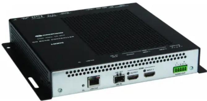
DMF-RMC-4K-SFPReceiver
TheDMF-RMC-4K-SFPenablesuncompressed4K/60videosignalextensionoverafiber opticcable.itis usedwithacompaniontransmitter (DMF-TX-4K-SFP or
DMCF-IX-4K-SFP)tosupportpoint-to-pointsignalextensionandmayalsobeusedto add4KfiberinputcapabilitytodDigitalMediaswitcher.
TheDMF-RMC-4K-SFPincludes oneHDMIinputfor connectionofanyHDor 4Ksource. SwitchingbetweentheDMandHDMI inputs canbeperformedautomaticallyusing autoswitching mode, manually using the onboard INPUT SEL (select) button, or through programmingviaaCrestroncontrolsystem.
NOTE:TheDMF-RMC-4K-SFP is soldaspartof akitthatincludes oneSFP+ transceiver module.
DMF-RMC-4K-SFP
natural_image
Exterior view of a black network switch device with ports and connectors (no visible text or symbols)DMCF-RX-4K-SFPReceiver Card
TheDMCF-RX-4K-SFPis afiber-basedreceiver carddesignedtofunction aspartof a Crestron4Kvideosignalextender solution,Itis usedwithacompaniontransmitter (DMF-TX-4K-SFP or DMCF-TX-4K-SFP).tosupportpoint-to-pointsignalextension,and mayalsobeusedtoadd4KfiberinputcapabilitytoaDigitalMediaswitcher.
TheDMCF-RX-4K-SFPinstalls inanyslotof aDMF-CI-8cardchassis.TheDMIN port allows for theinsertionof inappropriateSFP+transceivermoduletoenablecompatibility withmultimodeor single-modefiber.Italsofeaturesabuilt-in4K/60scaler,HDMI and analogaudiooutputs,diocalHDMI input,andaGigabitEthernetLAN port.
NOTE: TheDMCF-RX-4K-SFPis soldas partofakitthatincludes oneSFP+transceiver module.
DMCF-RX-4K-SFP

DMF-CI-8 Fiber Card Chassis
TheDMF-CI-8isa2-space,rack-mountablechassisdesignedtohouseuptoeight CrestronDMCF series cards.Withoneor morecards installed.theDMF-CI-8functionsas high-performance,fiber-basedsignalextendercapableof handlinguptoeightseparate uncompressed4Kvideosignals.Transmitter andreceiver cardsareavailableandcanbe installedinanyof theeightcardslots.InterchangeableSFP+transceiver modulesare utilizedbyeachcardtosupportmultimodeandsingle-modefiber types.Stand-alone transmitters andreceivers arealsoavailablefor installationatremotelocations. TheDMF-CI-8provides ameansfor adding4Kfiberinputs andoutputs toaCrestron DigitalMediaswitcher,EachcardconnectstoanHDMI,inputor outputontheswitcher,and tothelocalEthernetnetwork,allowingseamless routingof AVandcontrolsignals.The DMF-CI-8chassis does notswitch.itisacardchassis withapower supply. DMF-CI-8 (Front)
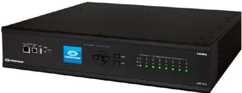
natural_image
Black CRESTOR PCI 8 network device with control panel and indicator lights (no readable text or symbols beyond branding)Thereof theDMF-CI-8accepts theDMCF series cards, Thetransmitter and receiver cards can occupy any card slot and any combination of card scan be installed. The example below show therear of the DMF-CI-8 with a fully occupied chassis containing four DMCF-RX-4K-SFP cards inslots 1–4 and four DMCF-TX-4K-SFP cards inslots 5–8. DMF-CI-8 (Rear ViewwithDMCF Cards Installed)

For more detailed information, seethe DMF-CI-8 page of the Crestron website.
SFP-10GTransceiver Module
CrestronSFP-10Gseries SFP+Transceiver Modules are designed for use with DMF Series DigitalMediaSEP+4KFiber Transmitters and Receivers and DMCF Series DigitalMedia SFP+4KFiber Transmitter and Receiver Cards. A choice of modules is offered to support multimodeor single-modefibertypes.
TheSFP-10Gtransceiver modulesarenormallysoldaspartafapackagedkitcontaining oneSFP+transceiver moduleandoneDMF or DMCP device. They are also available individually to allow for replacement in the field. SFP+modules provide fiber flexibility. The modules separate optics from the electronics.
NOTE: The fiber interface provided by the SFP+ transceiver module is not compatible with CrestronDMfiber(-F type, DM8Gfiber (-Stype, or DM8GSMfiber (-S2type devices.
SFP+ Transceiver Module (Dual LCConnectorsShown)
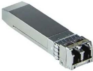
natural_image
Exterior view of a server rack with multiple ports (no visible text or labels)SFP+ Transceiver Module (ShownInstalledinDMF-TX-4K-SFP)
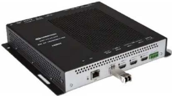
natural_image
Exterior view of a black network device with ports and connectors (no visible text or symbols)4K/60 Fiber DistributionSystem Application Examples
This section includes application examples of several different 4K/60 fiber distribution systems.
Long-DistancePoint-to-Point Fiber Run
The example below shows a fiber connection between a DMF-TX-4K-SFP transmitter and a DMF-RMC-4K-SFP receiver in a point-to-point application. The 4K/6- videocanbetransmitted over multimode fiber for distances upto1300ft(400 m) or over single-mode fiber for distances upto6.2miles (10km). An Ethernet LAN connection is also required to enable communication with the associated control system, The LAN connection can be made using the LAN port or either the fiber transmitter or the fiber receiver.
NOTE: The LAN ports of both the transmitter and receiver cannot be connected to the LAN simultaneously.
DMF-TX-4K-SFPandDMF-RMC-4K-SFPPoint-to-Point
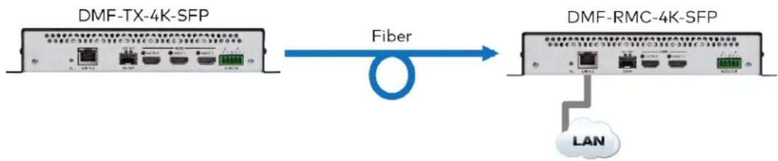
flowchart
graph LR
    A["DMF-TX-4K-SFP"] -->|Fiber| B["DMF-RMC-4K-SFP"]
    B --> C["LAN"]
Integration with aDigitalMedia Switcher
The example below shows a seamless integration of the 4K/60 fiber distribution system with a Digital Mediaswitcher.
NOTE: The DM-MD8X8(-CPU3) is shown as an example only. Anycard-based DigitalMediaswitcher (DM-MD8X8(-CPU3), DM-MD16X16(-CPU3), and DM-MD32X32(-CPU3)) as well as any blade-based DigitalMediaswitcher (DM-MD64X64 and DM-MD128X128) can be used.
Only single connections are shown, however, all fiber connections to the cards in the DMF-CI-8 require companion transmitter or receiver endpoint and every connection to the DM-MD8X8(-CPU3) requires an HDMI cable and a LAN cable. The information in parentheses (x4 and x8) denotes the actual number of connections that are necessary. The DME-CI-8 contains four DMCF-RX-4K-SFP cardsinslots1-4 and four DMCF-TX-4K-SFP cardsinslots5-8. Four DMF-TX-4K-SFP endpoints are required to connect to the four DMCF-RX-4K-SFP cards in the DMF-CI-8, totaling four fiber connections. The four DMCF-TX-4K-SFP cards require connections to four DMF-RMC-4K-SFP endpoints, totaling four fiber connections. The HDMI output of each DMCF-RX-4K-SFP card in the DMF-CI-8 can be connected to any available HDMI input on the switcher, adding a 4K fiber input to the switcher. The HDMI
input of eachDMCF-TX-4K-SFPcardintheDMF-CI-8canbeconnectedtoanyavailable HDMIoutputontheswitcher, addinga4Kfiberoutputtotheswitcher, Intheexample below a total of eightHDMI connections are required to connect the switchertothe DMCF-RX-4K-SFP and DMCF-TX-4K-SFP cards.
NOTE: When the HDMI output of a fiber receiver or an HDMI input of a fiber transmitter connects to a Digital Media switcher, the switchera automatically configures the P table of the fiber transmitter according to the SIMPL program. The fiber transmitter hosts the configuration settings of the fiber receiver.
For each pair containingatransmitter and companionreceiver,an Ethernet LAN connectionis requiredtoenablecommunication withtheassociatedcontrolsystem.ConnectiontotheLAN canbemadeusingtheLAN portoreither thefiber transmitter or thecompanionreceiver.TheLAN ports ofboththetransmitter andreceiver cannotbe connectedtotheLAN simultaneously.EightLAN connections arerequiredfor theeight pairs of fibertransmitters and companionreceiverthatconnecttheDMF-CI-8tothe DigitalMediaswitcher.
Logical IntegrationwithaDigitalMediaSwitcher
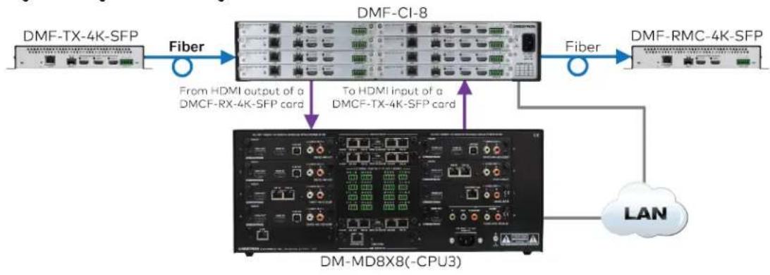
flowchart
graph LR
    A["DMF-TX-4K-SFP"] -->|Fiber| B["DMF-CI-8"]
    B -->|Fiber| C["DMF-RMC-4K-SFP"]
    B -->|From HDMI output of a DMCF-RX-4K-SFP card| D["DM-MD8X8(-CPU3)"]
    B -->|To HDMI input of a DMCF-TX-4K-SFP card| D
    D --> E["LAN"]
Fiber Distribution in a Single Room
The example below shows a4K/60fiber distributionsystemintegratedwithaDMPS3(4K DigitalMediapresentationsystem)for fiber distributioninasingleroom.
NOTE: The DMPS3-4K-150-Cis, shown as an example only. Any 4K Digital Media presentationsystem (DMPS3-4K-150-C, DMPS3-4K-50, and DMPS3-100-C) can be used.
TheHDMI outputofaDMF-RMC-4K-SFP connects toangavailableHDMI inputof the DMPS3-4K-150-C,addinga4Kfiber inputtotheDMPS3-4K-150-C.TheHDMIinputofthe DMF-TX-4K-SFPconnects totheHDMIoutputof theDMPS3-4K-150-C,addinga4Kfiber outputtotheDMPS3-4K-150-C.
Fiber DistributioninaSingleRoom
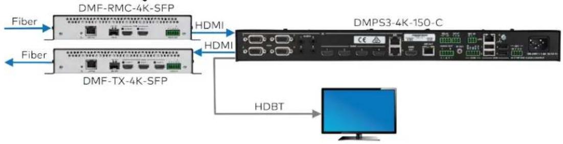
flowchart
graph LR
    A["Fiber"] --> B["DMF-RMC-4K-SFP"]
    C["Fiber"] --> D["DMF-TX-4K-SFP"]
    B --> E["HDMI"]
    D --> F["HDMI"]
    E --> G["DMPS3-4K-150-C"]
    F --> G
    G --> H["HDBT"]
    H --> I["Computer"]
Fiber Distribution Between Floors
The example below shows afiber connection between two floors with seamless integration of two Digital Medias switchers.
NOTE: The DM-MD8X8(-CPU3) is shown as an example only. Anycard-based DigitalMediaswitcher (DM-MD8X8(-CPU3), DM-MD16X16(-CPU3), and DM-MD32X32(-CPU3)) as well as any blade-based DigitalMediaswitcher (DM-MD64X64 and DM-MD128X128) can be used.
HDMI connections betweenaswitcher, thefiber transmitters, and companion receivers add4Kfiber outputsandinputs totheswitcher. Theswitcher automaticallyconfigure the IP tableofthefibertransmitters accordingtotheSIMPL program. Thefiber transmitters hosttheconfigurationsettings of the companion fiber receivers.
For each pair containing a transmitter and companion receiver, an Ethernet LAN connection is required to enable communication with the associated control system. The LAN connection can be made using the LAN port of either the fiber transmitter or companion receiver.
NOTE: The LAN ports of both the transmitter and receiver cannot be connected to the LAN simultaneously.
- OnFloor1,eightLAN connections are required for the eightpairs offiber transmitters and companion receivers that connect the DMF-CI-8tothe DigitalMediaswitcher.
- OnFloor2,onlyasingleLAN connectionfromtheDigitalMediaswitcher tothe LAN isrequired.
Fiber DistributionBetweenFloors
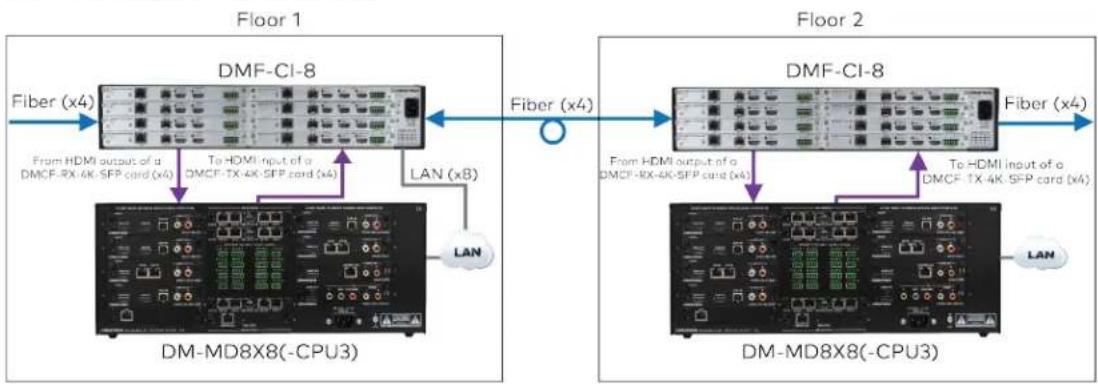
flowchart
graph LR
    subgraph Floor_1
        A["DMF-CI-8"] -->|Fiber (x4)| B["DM-MD8X8(-CPU3)"]
        C["From HDMI output of a DMCF-RX-4K-SFP card (x4)"] --> D["To HDMI input of a DMCF-TX-4K-SFP card (x4)"]
        E["LAN (x8)"] --> F["LAN"]
    end
    subgraph Floor_2
        G["DMF-CI-8"] -->|Fiber (x4)| H["DM-MD8X8(-CPU3)"]
        I["From HDMI output of a DMCF-RX-4K-SFP card (x4)"] --> J["To HDMI input of a DMCF-TX-4K-SFP card (x4)"]
        K["LAN"] --> L["LAN"]
    end
For moreinformationonTransmitter andReceiverkits,seetheDMF andDMCF. Series: DigitalMedig4K/60Fiber DistributionSystem ReferenceGuide(Doc.7948)onthe Crestronwebsite.
System Commissioning
CommissioningaDMsystem consists of:
- Proper ExtendedDisplayIdentificationData(EDID)configurationinDMTool software
• LinkQuality(LQ)tests
. DMTestReport
EDID Design
EDID designisjustas crucialassystemhardwaredesign.EDID istheinformationthat tells asourcewhatresolutiontooutputwhenitis pluggedin,EDID dataflows inreverse from theAVinformation,sothedisplaytellsthesourcewhatitwants—nottheother way around.
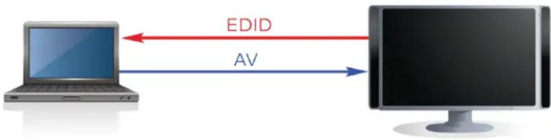
flowchart
graph LR
    A["Laptop"] -->|EDID| B["Monitor"]
    B -->|AV| A
Insomecases, theuser can adjust the output resolution of the source, but not without a valid EDID table from the display. APC allow the user to choose a resolution from the list provided in the display settings. That lists generated by the display and is sent to the PC.
DigitalMediadistributes EDID to all the source that are attached. This EDID table should be manually set by the system commissioner and considered part of a completesystem design. While automatic mode guarantees that something appears on the screen, it cannot guarantee the customer is seeing what they want.
DMToolsoftware(availableinCrestronToolbox) allows the user to manually configure the EDID table, while complying with all therules of EDID. There are only some any entries that can exist in an EDID table, which mean every resolution cannot be listed. Signal type (VGA, DVI, HDMI) impacts the EDID table size. HDMI signals allow for more EDID entries than DVI and VGA (an important consideration when choosing sources).
StartEDIDtabledesignbyansweringtwoquestions:
- How does the customer expect the system to work?
- For residentialsystems,theanswer maybeassimpleas "Iwant1080pvideo everywhere."
- Incommercialsystems, the customer may want to choose from a number of sources, including using alaptoptodisplayonaprojector.
- What is thenativeresolution of eachdisplayinthesystem? If alldisplaysdonot sharethesamenativeresolution, is thereacommmonresolutionacross all?
Thedesignermustprocess this dataandcameupwithanEDID tablethatsatisfiesboth requirements.Insomecases,resolutionconflicts preventthedesigner fromsendingthe highestqualityvideotoalldisplays.DMreceivers thatfeaturevideoscalers,suchasthe DM-RMC-SCALER-C,canbeusedtoensurethateachdisplayprovidesthebestresolution itcansupport.For additionalinformation onEDID design,seeEDID.
Link Quality Test
The Link Quality (LQ) button is available on DM 8G+ and 8G Fiber devices. Press this button torunaquicktestonthestatusof.theDMconnectionbetweentheDMdevices.Basedona bit-error test,oneof thefollowingstates is reported.
StatusCode StatusText Notes
Green Linkis good No action isrequired
Red Linkis unstable ordown Terminations andcableshouldbe checked
LinkQualityExample
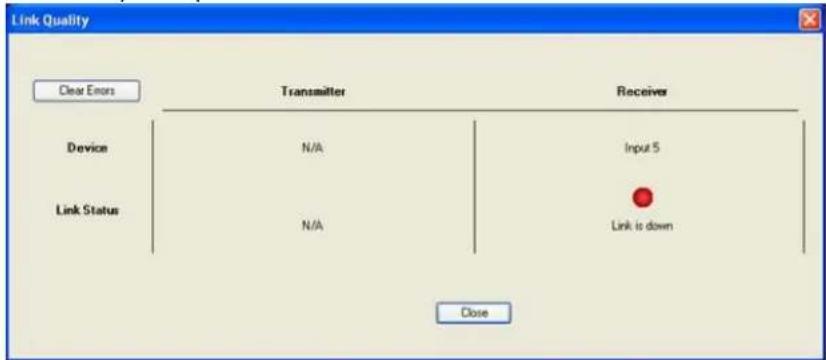
DMTest Report
TheDMTestReportis thefinaldocumentgeneratedbyDMTool.Thereportprovidesa comprehensivesummaryoftheDMsystem,documentinginputs,outputs,EDIDsettings,HDCPstatus,andanyopenitems or notices thatmayimpactsystem performance.This reportcanbeprovidedtothesystem designer and/or clientasafinalnoticeregardingthe system's configuration andstatus.
DM8G+PowerConsiderations
Eachfiber-basedDMandDM8G+endpointships withapowersupply.SomeDM8G+ devicescanbepoweredviaPoDMor PoDM+inplaceof usingtheincludedpower supply.
. DM8G+inputandoutputcards haveaPOEIN portfor eachDMport.
- ConnectaPoDMor PoDM+power sourcetoeachPOEIN inputandoutputcard (dependingontheendpointtype)toprovidepower.
- ThesameCAT5eor better cablethatcarries videoandaudioalsocarries power to theDMendpoint.
• ThePWE-4803RU CEN-SW-POE-5 CEN-SW-POE-24 CEN-SW-POE-24, DM-PSU-8, and DM-PSU-16 supply PoDM for use with DM8G+.
• The CEN-SW-POE-16, DM-PSU-ULTRA-MIDSPAN, DM-PSU-8-PLUS, and DM-PSU-16-PLUSsupplyPoDMandPoDM+for use with DM8G+.
- TheDMPS3-200-C,DMPS3-300-C,andDMPS3-300-C-AECprovidePoDMviatheir companionPower over DMsupply. Theseproducts donotsupportPoDM+power. TheysupplyonlyPoDM.
- TheDMPS3-4K-50,DMPS3-4K-100-C,andDMPS3-4K-150-CprovidePoDMvia their companion Power over DM supply. These products donot support PoDM+ power. They supply only PoDM.
- TheDM-RMC-100-C,DM-RMC-4K-100-C,DM-TX-200-C-2G,DM-TX-201-C,DM-TX-4K-202-C,DM-TX-401-C,andRMC-4KZ-100-Cendpoints canbepowered viaPoDM,TheDMPS3-4K-250-CandDMPS3-4K-350-Cprovidepower toPoDM+ powereddevices
• TheDM-RMC-4K-SCALER-C,DM-RMC-4K-SCALER-C-DSP,DM-TX-4K-302-C,DM-TX-4KZ-202-C,andDM-TX-4KZ-302-CendpointscanbepoweredviaPoDM+.
- TheDM-TX-4K-302-CcanbepoweredbyaPoDMPSE(Class 3)if noUSBdeviceis connectedtotheUSBHID port.
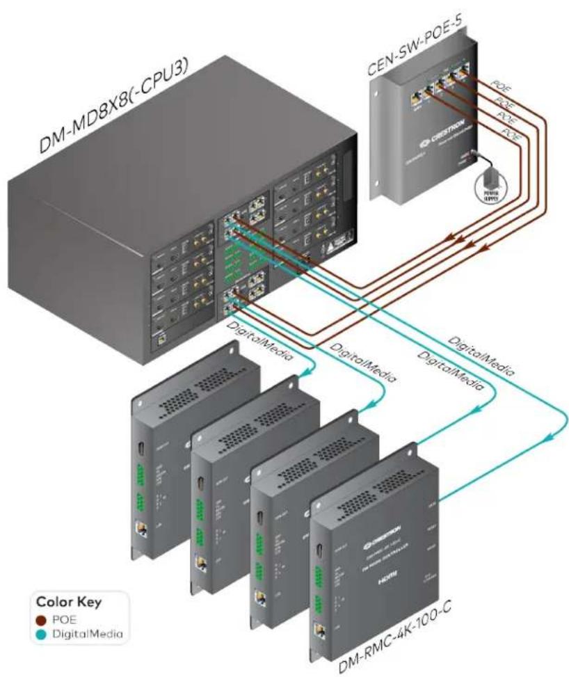
flowchart
graph TD
    A["DM-MD8X8(-CPU3)"] -->|DigitalMedia| B["CEN-SW-POE-5"]
    B -->|DigitalMedia| C["DM-RMC-4K-100-C"]
    C -->|DigitalMedia| B
    style A fill:#99ccff,stroke:#333
    style B fill:#99ccff,stroke:#333
    style C fill:#99ccff,stroke:#333
    note right of A
        Color Key: POE (Red), DigitalMedia (Teal)
    end
AppendixA: DigitalMedia Network Considerations
MostCrestronDigitalMediadevices areEthernetdevices, Ethernettrafficdueto. DigitalMediadevicesis relatively low. The custom controlsystemprogramthatties theDM system together dictates howmuchbandwidth is needed.
DigitalMediaCertifiedDesigners andEngineers
EveryCrestronDMsystemshouldbedesignedbya DigitalMediaCertifiedDesigner- 4K(DMC-D-4K)and commissionedbyaDigitalMediaCertifiedEngineer - 4K (DMC-E-4K).
Only Crestroncertifiedengineers ensurethatasystemis properly installed and configured to Crestronstandards. The information in this section is intended to explain basic DMI, Paddressing considerations. Consult the DMC-E with further questions.

DigitalMedia System Topology
EachDMlink(connectionbetweentwoDMdevices)carries Ethernetembeddedinside. Therefore, no additional wiring is needed to provide network connectivity for third-party Ethernet products installed the endpoints. Interconnected DM devices need only as single point (typically themainswitcher) to be connected to the LAN in order to provide Ethernet to all devices in the system. To facilitate this Crestron DM devices have integrated, managed Ethernet switches and an exposed Ethernet port.
NOTE: ADMendpointisanyDMtransmitteror receiver.
DigitalMedia EthernetConnectivity
Inthescenariobelow, Ethernetconnectivity is provided to all IDM devices and third-party devices from the single LAN connection at the DM-MD8X8 (-CPU3). This eliminates the needtorunextrawiringtoeachlocation to provide Ethernetconnectivity. DigitalMediaEthernetConnectivity
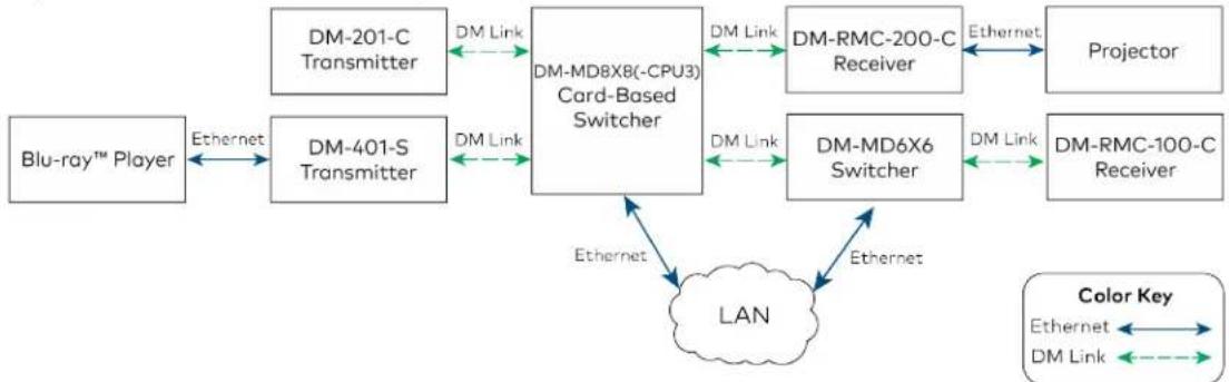
flowchart
graph LR
    A["Blu-ray™ Player"] -->|Ethernet| B["DM-401-S Transmitter"]
    B -->|DM Link| C["DM-MD8X8(-CPU3) Card-Based Switcher"]
    C -->|DM Link| D["DM-RMC-200-C Receiver"]
    D -->|Ethernet| E["Projector"]
    C -->|DM Link| F["DM-MD6X6 Switcher"]
    F -->|DM Link| G["DM-RMC-100-C Receiver"]
    G -->|Ethernet| H["LAN"]
    H -->|Ethernet| C
    H -->|Ethernet| I["Color Key"]
    I -->|Ethernet| J["DM Link"]
    I -->|Ethernet| K["DM Link"]
ThemainEthernetuplinktoaDMsystem occurs attheDigitalMediaswitcher. Thefollowingswitchers have10/100/1000BaseTauto-negotiatinguplinkports: DM-MD6X4,DM-MD6X6,DM-MD8X8(-CPU3),DM-MD16X16(-CPU3), DM-MD32X32(-CPU3),andallDMPSmodels. TheDM-MD6X1switcherhas10BaseT/100BaseTXauto-negotiatinguplinkports.
PrivateNetwork Mode
Prior to2012, everyDMcardandendpointinaninstallationrequiredits ownIPaddress on thecorporatenetwork.In2012,CrestronintroducedPNMtoDMswitchers.PNMgreatly reduces thenumber of IPaddressesrequiredfor DMin Installations.Crestron recommends usingPNMtomanageEthernetsettingsfor DMcards andendpoints connectedtoaDM switcher.Othermethodsarenotrecommended.For details onlegacymodes ofoperation, seeCrestronTrueBlueOnlineHelp.
NOTE:PNMis notapplicable to standalone installations involving directly connected DM endpoints with no associated DM switchers. In these installations each endpoint device needs its own IP address, either configured manually or via DHCP.
PNMcreatesacompletelyprivateIPnetworkfor.allDMcards andendpoints that are connectedtotheDMswitcher, effectivelyisolatingthemfrom thebuildingnetwork,PNM significantlystreamlines,homeandorganizationalinfrastructures,conservesIP addresses, reduces costs,andsimplifies systemmanagementandtroubleshooting.
Theonlydevicethatappears onthebuildingnetworkis theDMswitcher,Theswitcher needsjustoneIP address,whichcaneitherbesetstaticallyor assignedviathebuilding's DHCPserver.InPNMmode,noneof thecardasor endpoints aredirectlyreachableviathe networkof_thebuilding.Instead,communicationwiththesedeviceismanagedthrough themainDMswitcher.ThedevicesconnectedtotheLAN ports foundonmainyDM endpoints remainvisibletothenetwork.SeePrivateNetworkModewithAuxiliaryDevices for anillustration.
ThemainDMswitcherCPUis theonlydeviceconnectedtobothnetworks.TheCPUmay receiveaninstructiononthepublic network(suchasfromaCrestroncontrolsystem)and createanewinstructionfor adeviceontheprivatenetwork(DMcard,blade,or endpoint). AtnotimedoesanEthernetpacketfromthepublicnetworktraversetotheprivate network,andnoprivateEthernetpackets traversetothepublic network.
For mostinstallations, such as incorporateor universitysettings, using PNMisthebest practice because it does not be a highly impact then network. PNMalsoisolates DM-related traffic.
NOTES:
- PNMisenabledbydefaultonallnewunits andisenableduponsystem restore. PNMisonlyavailableinPUF (firmwarepackageupdatefile)2.40or later.
- PNMisnotconfigurableonswitchers equippedwiththeDMC-CPU3,whereitis alwaysenabled.
- DMP S unitsrequiretwoIP addresses. Boththeintegratedcontrolprocessor and theintegratedDMequipment(switcherandallendpoints)requiretheir ownIP address.
- If anendpointis connectedtoaDMswitcher,its_LAN connector mustnotbe connectedtothecorporatenetwork.Inthis configurationLAN ports areonlyfor connectiontodevices suchaslaptops,Blu-ray™players,orprojectors.
Private NetworkMode ConfigurationOptions
PNM ON/OFF
Mode Comments
PNMON Static Assigns one IP address to the mainDMswitcher
PNMON DHCP Takes one IP address from the DHCP server
PNMOFF* StaticandDHCP
Çanbe inStaticgrDHCP mode
Requires manyIP addresses
Notrecommendedformostinstallations
* Applies to DM-MD8X8, DM-MD16X16, and DM-MD32X32 with DMC-CPU only. PNM is not configurable on switchersequipped with the DMC-CPU3, where it is always enabled.
Private NetworkMode with AuxiliaryDevices
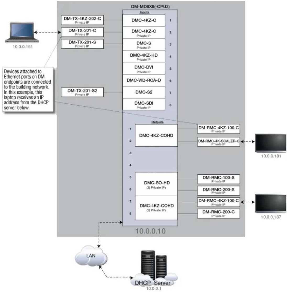
flowchart
graph TD
    A["10.0.0.151"] --> B["DM-TX-4KZ-202-C Private IP"]
    A --> C["DM-TX-201-C Private IP"]
    A --> D["DM-TX-201-S Private IP"]
    B --> E["DM-MD8X8(-CPU3)"]
    C --> E
    D --> E
    E --> F["Inputs"]
    F --> G["DMC-4KZ-C"]
    F --> H["DMC-4KZ-C Private IP"]
    F --> I["DMC-S Private IP"]
    F --> J["DMC-4KZ-HD Private IP"]
    F --> K["DMC-DVI Private IP"]
    F --> L["DMC-VID-RCA-D"]
    F --> M["DMC-S2"]
    F --> N["DMC-SDI Private IP"]
    O["Devices attached to Ethernet ports on DM endpoints are connected to the building network. In this example, this laptop receives an IP address from the DHCP server below."] --> P["DM-TX-201-S2 Private IP"]
    P --> Q["Outputs"]
    Q --> R["DMC-4KZ-COHD"]
    Q --> S["DMC-SO-HD (2) Private IPs"]
    Q --> T["DMC-4KZ-COHD (2) Private IPs"]
    U["LAN"] --> V["DHCP Server 10.0.0.1"]
    V --> W["Output"]
    W --> X["DM-RMC-4KZ-100-C Private IP"]
    W --> Y["DM-RMC-4K-SCALER-C Private IP"]
    Z["10.0.0.181"] --> AA["Output"]
    AB["10.0.0.187"] --> AC["Output"]
NOTES:
- DHCP-distributedIPaddresseshavebeenchosenatrandomtoshowthat devices attachedtoDMendpoints areconnectedtothebuildingLAN.
- The devices enclosed in the gray box are isolated from the customernetwork but are accessible through the Paddress assigned to the DM-MD8X8(-CPU3).
MultipleDigitalMedia Switchers Using Private Network Mode
Whentwoor, moreswitchers, areconnectedviaDMlinks,theyareconsideredcascaded. EachDMswitcher, inacascadedsystemmustbeconfiguredwithauniqueSystemID.This prevents IP conflictsamongDMdevices ontheprivatenetwork.Intheillustrationbelow, onlyoneIP address per switcher isrequiredfromthebuildingnetwork.
Multiple DMSwitchers UsingPNMExample
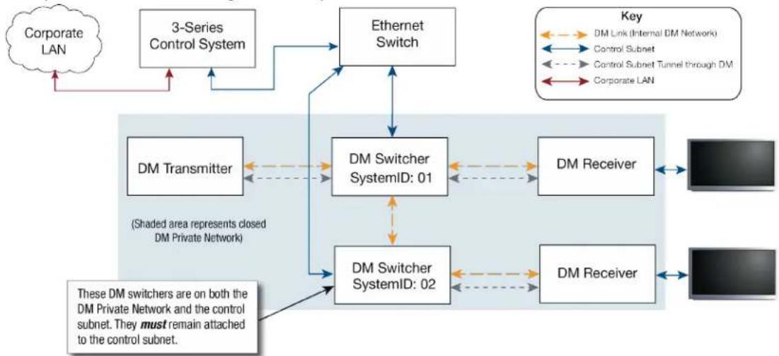
flowchart
graph TD
    A["Corporate LAN"] --> B["3-Series Control System"]
    B --> C["Ethernet Switch"]
    C --> D["DM Switcher SystemID: 01"]
    D --> E["DM Receiver"]
    E --> F["DM Receiver"]
    F --> G["DM Transmitter"]
    G --> D
    D --> H["DM Switcher SystemID: 02"]
    H --> I["DM Receiver"]
    I --> J["DM Receiver"]
    J --> K["DM Transmitter"]
    K --> L["DM Switcher SystemID: 01"]
    L --> M["DM Receiver"]
    M --> N["DM Receiver"]
    N --> O["DM Transmitter"]
    O --> P["DM Switcher SystemID: 02"]
    P --> Q["DM Receiver"]
    Q --> R["DM Receiver"]
    R --> S["DM Transmitter"]
    S --> T["DM Switcher SystemID: 01"]
    T --> U["DM Receiver"]
    U --> V["DM Receiver"]
    V --> W["DM Transmitter"]
    W --> X["DM Switcher SystemID: 02"]
    X --> Y["DM Receiver"]
    Y --> Z["DM Receiver"]
    Z --> AA["DM Transmitter"]
    AA --> AB["DM Switcher SystemID: 01"]
    AB --> AC["DM Receiver"]
    AC --> AD["DM Receiver"]
    AD --> AE["DM Transmitter"]
    AE --> AF["DM Switcher SystemID: 02"]
    AF --> AG["DM Receiver"]
    AG --> AH["DM Receiver"]
    AH --> AI["DM Transmitter"]
    AI --> AJ["DM Switcher SystemID: 01"]
    AJ --> AK["DM Receiver"]
    AK --> AL["DM Receiver"]
    AL --> AM["DM Transmitter"]
    AM --> AN["DM Switcher SystemID: 02"]
    AN --> AO["DM Receiver"]
    AO --> AP["DM Receiver"]
    AP --> AQ["DM Transmitter"]
    AQ --> AR["DM Switcher SystemID: 01"]
    AR --> AS["DM Receiver"]
    AS --> AT["DM Receiver"]
    AT --> AU["DM Transmitter"]
    AU --> AV["DM Switcher SystemID: 02"]
    AV --> AW["DM Receiver"]
    AW --> AX["DM Receiver"]
    AX --> AY["DM Transmitter"]
    AY --> AZ["DM Switcher SystemID: 01"]
    AZ --> BA["DM Receiver"]
    BA --> BB["DM Receiver"]
    BB --> BC["DM Transmitter"]
    BC --> BD["DM Switcher SystemID: 02"]
    BD --> BE["DM Receiver"]
    BE --> BF["DM Receiver"]
    BF --> BG["DM Transmitter"]
    BG --> BH["DM Switcher SystemID: 01"]
    BH --> BI["DM Receiver"]
    BI --> BJ["DM Receiver"]
    BJ --> BK["DM Transmitter"]
    BK --> BL["DM Switcher SystemID: 02"]
    BL --> BM["DM Receiver"]
    BM --> BN["DM Receiver"]
    BN --> BO["DM Transmitter"]
    BO --> BP["DM Switcher SystemID: 01"]
    BP --> BQ["DM Receiver"]
    BQ --> BR["DM Receiver"]
    BR --> BS["DM Transmitter"]
    BS --> BT["DM Switcher SystemID: 02"]
    BT --> BU["DM Receiver"]
    BU --> BV["DM Receiver"]
    BV --> BW["DM Transmitter"]
    BW --> BX["DM Switcher SystemID: 01"]
NOTE: The SystemID can range from 01 to 64 and must be unique for each DM switcher. By default, the SystemID is set to 01. The ID can be set via the front panel, the SIMPL program, or the System Infotoolin Crestron Toolbox. Each DM switcher must be directly connected to the corporate LAN. One DM switcher cannot receive Ethernet via another DM switcher, and each DM switcher must receive an IP address from the control subnet.
Rapid Spanning Tree Protocol(RSTP)
SinceDMdevices embedEthernetineverylink,avalidAVconfigurationcancreatenetwork loops,suchas routingtwoAVsignalsfrom oneswitcher toanother switcher.Toeliminate anynetworkloopingproblems.DMproducts implementIEEE802.1wRSTP(Rapid SpanningTreeProtocol).WithPNDisabled,theDMswitcher managestheDMEthernet links topreventnetworkloops.
DMproducts transmitBridgeProtocolDataUnits(BPDU)per theRSTPspecification. WithPNDisabled,BPDUs areisolatedtotheprivatenetworkandarenotvisibletothecorporatenetwork.RSTPis notenabledonuser-accessibleLAN connectors,Topreventnetworkloops,endpoints shouldnotbeconnectedtothecorporateLAN inthis configuration.
Bydefault, every DMswitcher ships with PNmandRSTP enabled. If PNMisdisabled, RSTP remains enabled. If required, disable RSTP and manage Ethernet ports manually.
NOTE:PNMisnotconfigurableonswitchers equippedwiththeDMC-CPU3,whereitis always enabled.
MultipleSpanningTreeProtocol(MSTP),whichis anadvancedversionof RSTP,supports multiblespanningtreesonmultipleVLANs.DMimplementsRSTPbutnotMSTP.Ifruhing MSTP,onthenetwork,ensurethatthenetworkporttowhichDMisconnectedonlybelongs tooneVLAN.This is onlyaproblemifPNM is disabled.
ManagedEthernetswitchescanbeconfiguredtohaveedgeports.Ethernetswitches cannotbepluggedintoedgeports.
. If PNMis enabled,aDMswitcher iscompatiblewithedgeports.
- If PNM is disabled, the managed Ethernet switches may consider the DM system to bean Ethernet switch and shutdown the edge port.
DMEthernetWiringExample
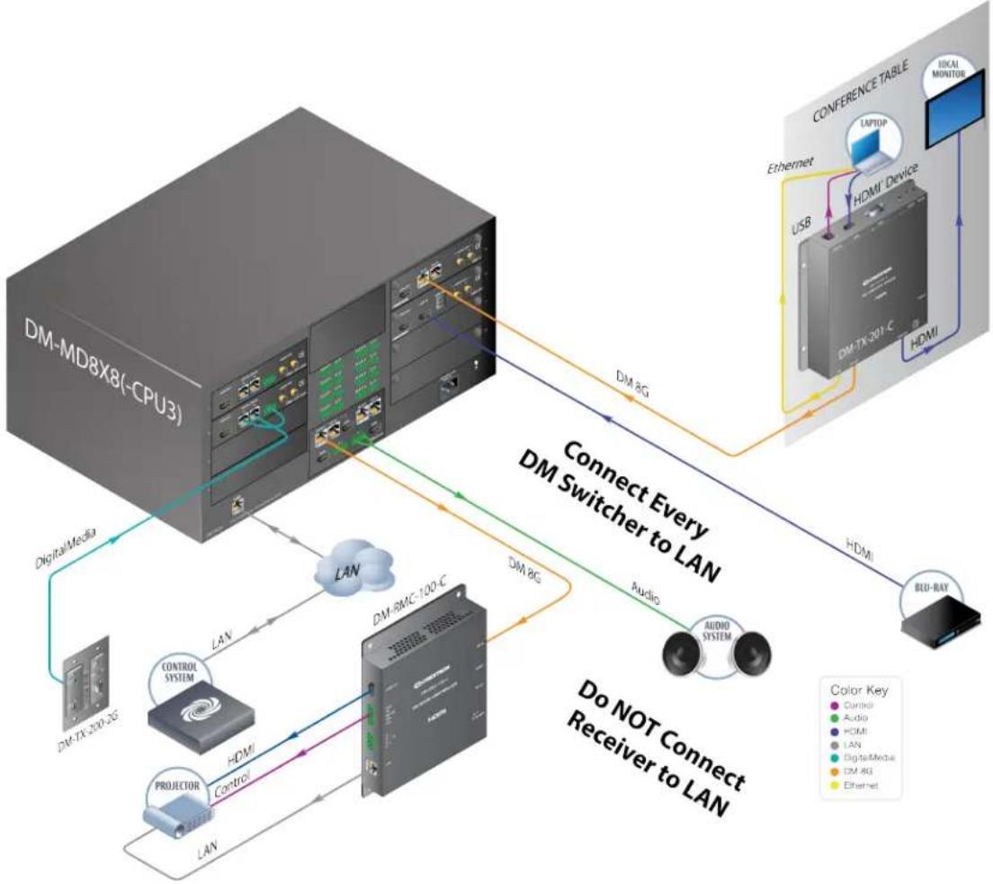
flowchart
graph TD
    A["DM-MD8X8(-CPU3)"] -->|Connect Every DM Switcher to LAN| B["CONference Table"]
    B -->|Do NOT Connect Receiver to LAN| C["Audio System"]
    C -->|LAN| D["Control System"]
    D -->|LAN| E["DM-8MC-120-C"]
    E -->|LAN| F["DM-TC-200-3G"]
    F -->|DigitalMedia| G["Digital Media"]
    G -->|LAN| H["DM-8G"]
    H -->|LAN| I["DM-8G"]
    I --> J["Output"]
    style A fill:#f9f,stroke:#333
    style B fill:#ccf,stroke:#333
    style C fill:#cfc,stroke:#333
    style D fill:#fcc,stroke:#333
    style E fill:#cff,stroke:#333
    style F fill:#ffc,stroke:#333
    style G fill:#cfc,stroke:#333
    style H fill:#fcc,stroke:#333
    style I fill:#ffc,stroke:#333
NOTES:
- DMswitchers should be the only devices in the DM system connected to the LAN.
- Ensure that the System ID of each DM switcher in the system is unique.
. Donotconnectroom controllers or transmitters totheLAN.
AppendixB:DMCablePlant Certification
DigitalMediqinfrastructurewiringsshouldbetestedbeforeconnectingDMequipment.The basicmethodstocertifythecableplantfor DigitalMediaareoutlinedbelow.The certifications areverytypicalfor anEthernetdatanetwork(mostotheterminologyand valuesarefunctionsandvocabularyofthetestequipment).
DM8G STPCable (DM-CBL-8G)
ThecableshouldbecertifiedtoEIA/TIA-568CAT5ewithatestmeter usingthefollowing:
. Channelor CAT5ePermalinktest
. FTP(foiltwistedpair)cablewiththeshieldtest
. Nominalvelocityof propagationis at69%
. T568Bwiringrecommended(useT568Aifthatistheplant's wiring)
DMUltra Cable (DM-CBL-ULTRA-NP and DM-CBL-ULTRA-P)
. Channelor CAT6aPermalinktest
. S/FTP (shielded,foiltwistedpair)cablewiththeshieldtest
. Nominalvelocityof propagationis at74% (non-plenum)and78%(plenum)
If certifyingpatchpoints, usethePermalink test, which assumes shortpatch cables may be used one either end. If certifying the entire communications channel from port to port, usetheChanneltest(seetheNOTEbelow).
Permalink Channel TestExample
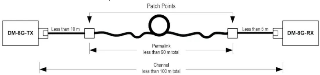
NOTE: Totalpatchings should not exceed 33ft (10m). Patching on the DM8GRX side should not exceed 16ft (5m).
Multimode and Single-mode Fiber
Multimodeandsingle-modefiber shouldbetested for optical loss in accordance with their respective IIA/IEC test standards. The optical time domain reflectometer (OTDR) method of testing is strongly recommended. Each fiber end should be inspected with a 100x-200x microscope and cleaned if necessary before testing.
Fiber links should always be tested and to end for optical insertion loss. The following illustrations shows atypical fiber link being tested, along with the associated test equipment. Not that patch cords and infrastructure fiber are included in the test.
Typical Fiber LinkTestExample

flowchart
graph LR
    LS --> A
    A --> B
    B --> C
    C --> D
    D --> PM
    style LS fill:#f9f,stroke:#333
    style PM fill:#bbf,stroke:#333
    subgraph Light Source
        A
        B
        C
        D
    end
    subgraph Launch Cord
        A
        B
    end
    subgraph Patch Cord
        A
        B
        C
    end
    subgraph Infrastructure Cable
        B
        C
    end
    subgraph Patch Cord
        A
        B
        C
    end
    subgraph Receive Cord
        D
    end
    subgraph Power Meter
        PM
    end
Connector pairs BandRepresentinfrastructurepatchpanels whilepairs AandD representcouplers.Thecouplers connectthefiberlinkbeingtestedtothelaunchcordand receivecordassociatedwiththetestequipment.
Multimodefibercables should be tested in accordance with TIA-526-14-BOFSTP-14-B Method B (one-cord reference method). The European equivalent standards IEC 61280-4-1.
Multimodefibers should be tested with 850nm and 1300nm wavelength sources. Dueto the comparatively short lengths of multimodefiber runs and the varying fiber lengths supported by CRESFIBER8G and OM3, Crestronhas, simplified the acceptable loss requirement for multimodefiber. Acceptable insertion loss for each fiber linkendtoendis <4dB@850nmand<4 dB@1300nm.
Single-modefiber cableshallbetestedinaccordancewithTIA-526-7OFSTP-7MethodA.1 (onejumper-cablemeasurement).theEuropeanequivalentstandardis IEC61280-4-2. Single-modefibers shouldbetestedwith1310nm, and1550nm wavelengthsources. Acceptableloss for eachwavelengththis determinedbythesumof twofactors.
- Number of connector pairs that are being tested: A connector pairmates at each coupler or patch panel. The maximum allowed loss per pair is 0.75dB.
- Totalfiber length:Theacceptableloss is definedindBperkilometer andvaries by wavelength.
The following table show the acceptable insertion loss per kilometer at each wavelength for CRESFIBER8G-SM-P.
Wavelength(nm) Maximum Attenuation (dB/km)
| 1310 | 0.4 |
| 1550 | 0.3 |
Tocalculatethemaximum, acceptableattenuation, addthelossesallowedper, connector pairtotheloss allowedinthefiber. For example, a10kmlinkmaximumallowedfiber loss (F) is calculatedasfollows:
F = 0.4^10 = 4 dB@1310nm F = 0.3^10 = 3 dB@1550nm
Thetotallinkloss (L)for theexampleaboveis as follows:
L=F +A+B+C+D=4+0.75 +0.75+0.75 +0.75=7dB@1310nm
L=F +A+B+C+D=3+0.75+0.75+0.75+0.75=6 dB@1550nm
Bycomparison, the maximum allowed attenuation for a500m fiber links less than half that of a10km link:
L = F + A + B + C + D = 0.20 + 0.75 + 0.75 + 0.75 + 0.75 = 3.2dB@1310nm L = F + A + B + C + D = 0.15 + 0.75 + 0.75 + 0.75 + 0.75 = 3.15dB@1550nm
L=A+B+C=0.75+0.75+3=4.5 dB@1550nm
Theequipmentneededfor testingis:
• Fiber OpticMicroscope(for example,SPCfiber DI-200FiberOpticInspectionScope
. Fiber OpticCleaningWipes (for example,wipes includedwithCRESFIBER-TK)
. MultimodeFiber OpticLoss TestKit
- Single-modeFiber Optic Loss TestKit(for example, CKSM-2Contractor Series Multimode and Single-mode TestKit)
Whyis alonger fibercableallowedtohavemoreloss?
An8Receiver should accept a certain fixed amount of power loss over a fiber link regardless of length. These numbers are more than just a measurement of optical power losses. They are an indicator of connector termination quality and fiber integrity. Poorly terminated connectors and kinked fibers cause easy-to-measure optical power losses as well as other problematic but difficult-to-measure artifacts such as optical reflections. A short, poorly-terminated single-modified fiber with dBof loss may output the same optical power as much longer, well-terminated fiber. However, the short fiber has reflection issues that may result in video loss or other link problems.
TestHDMI Cables
HDMlcables shouldbetestedusingaQuantumData780wiretestfunction.
AppendixC:ApplicationDiagrams
This section provides examples of several different Digital Mediasystem applications. For more information, seetheDigitalMediapageontheCrestronwebsite.
Residential Multiroom Distribution
Multiroom distributioninresidentialenvironments involvescombiningseveralsources and formattypes, withdifferentialdisplaymanufacturers andresolutions.CrestronDigitalMedia enablesdistribution,resolutiondetermination,andHDCPmanagementacross.aminimal wholehomeinfrastructure.Theexamplebelowshows multiroom distributionina residentialenvironment.
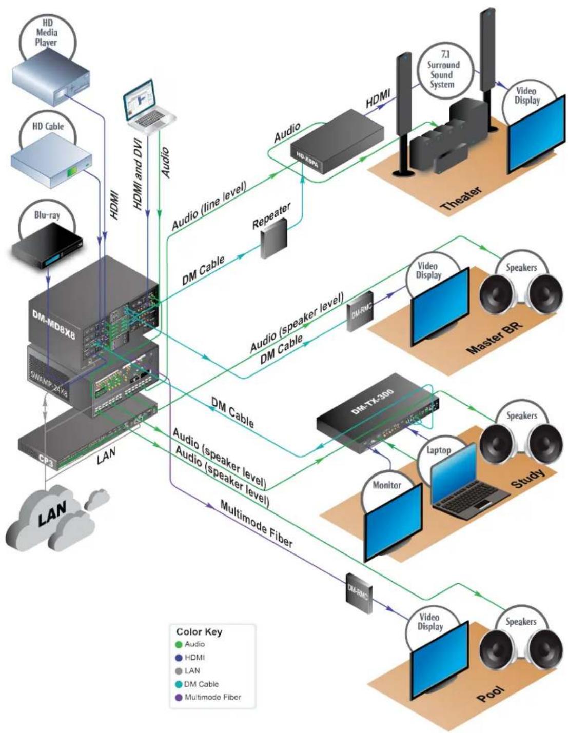
flowchart
graph TD
    subgraph LAN
        A["CPU"] -->|HDMI and DVI| B["HD Media Player"]
        C["HD Cable"] -->|HDMI| B
        D["Blu-ray"] -->|HDMI| B
        E["DM-MDBX8"] -->|HDMI and DVI| F["Audio"]
        G["SWAMR-25V8"] -->|HDMI and DVI| F
        H["DHMI"] -->|Audio (line level)| I["Audio"]
        J["Audio (speaker level)"] --> K["Audio (speaker level)"]
        L["Audio (speaker level)"] --> M["Audio (speaker level)"]
        N["Audio (speaker level)"] --> O["Audio (speaker level)"]
        P["Audio (speaker level)"] --> Q["Audio (speaker level)"]
        R["Audio (speaker level)"] --> S["Audio (speaker level)"]
        T["Audio (speaker level)"] --> U["Audio (speaker level)"]
        V["Audio (speaker level)"] --> W["Audio (speaker level)"]
        X["Audio (speaker level)"] --> Y["Audio (speaker level)"]
        Z["Audio (speaker level)"] --> AA["Audio (speaker level)"]
        AB["Audio (speaker level)"] --> AC["Audio (speaker level)"]
        AD["Audio (speaker level)"] --> AE["Audio (speaker level)"]
        AF["Audio (speaker level)"] --> AG["Audio (speaker level)"]
        AH["Audio (speaker level)"] --> AI["Audio (speaker level)"]
        AJ["Audio (speaker level)"] --> AK["Audio (speaker level)"]
        AL["Audio (speaker level)"] --> AM["Audio (speaker level)"]
        AN["Audio (speaker level)"] --> AO["Audio (speaker level)"]
        AP["Video Display"] --> AQ["7.1 Surround Sound System"]
        AR["Video Display"] --> AS["Theater"]
        AT["Laptop"] --> AU["Laptop"]
        AV["Laptop"] --> AW["Laptop"]
        AX["Laptop"] --> AY["Laptop"]
        AZ["Laptop"] --> BA["Laptop"]
        BB["Laptop"] --> BC["Laptop"]
        BD["Laptop"] --> BE["Laptop"]
        BF["Laptop"] --> BG["Laptop"]
        BH["Laptop"] --> BI["Laptop"]
        BJ["Laptop"] --> BK["Laptop"]
        BL["Laptop"] --> BM["Laptop"]
        BN["Laptop"] --> BO["Laptop"]
        BP["Laptop"] --> BQ["Laptop"]
        BR["Laptop"] --> BS["Laptop"]
        BT["Laptop"] --> BU["Laptop"]
        BV["Laptop"] --> BW["Laptop"]
        BX["Laptop"] --> BY["Laptop"]
        BZ["Laptop"] --> CA["Laptop"]
        CB["Laptop"] --> DA["Laptop"]
        DB["Laptop"] --> DBL["Laptop"]
        DC["Laptop"] --> DBM["Laptop"]
        DBM["Laptop"] --> BEM["Laptop"]
        BEM["Laptop"] --> BQM["Laptop"]
        BFM["Laptop"] --> BQM
        BQM["Laptop"] --> BQM
        CAM["Laptop"] --> BQM
        BQM["Laptop"] --> BQM
        BQM["Laptop"] --> BQM
    end

    subgraph Theater
        C
        D
    end

    subgraph Master BR
        E
        F
    end

    subgraph Study
        G
        H
    end

    subgraph Pool
        I
        J
    end

    subgraph Audio
        K
    end

    subgraph Audio Cable
        L
    end

    subgraph Audio Fiber
        M
    end

    subgraph Multimode Fiber
        N
    end

    subgraph Color Key
        O
    end

    style A fill:#f9f,stroke:#333
    style B fill:#ccf,stroke:#333
    style C fill:#cfc,stroke:#333
    style D fill:#fcc,stroke:#333
    style E fill:#cff,stroke:#333
    style F fill:#ffc,stroke:#333
    style G fill:#cfc,stroke:#333
    style H fill:#cfc,stroke:#333
    style I fill:#cfc,stroke:#333
    style J fill:#cfc,stroke:#333
    style K fill:#cfc,stroke:#333
    style L fill:#cfc,stroke:#333
    style M fill:#cfc,stroke:#333
    style N fill:#cfc,stroke:#333
    style O fill:#cfc,stroke:#333
    style P fill:#cfc,stroke:#333
    style Q fill:#cfc,stroke:#333
    style R fill:#cfc,stroke:#333
    style S fill:#cfc,stroke:#333
    style T fill:#cfc,stroke:#333
    style U fill:#cfc,stroke:#333
    style V fill:#cfc,stroke:#333
    style W fill:#cfc,stroke:#333
    style X fill:#cfc,stroke:#333
    style Y fill:#cfc,stroke:#333
    style Z fill:#cfc,stroke:#333
Commercial VideoConferenceRoom
Videoconferencerooms requirecombiningdisparatemediatobetransmittedtoremote locations and multiple local display simultaneously. All teleconferencecodesnowprovide anHD signal via HDMI with HDCP. The Crestron Digital Media distributionsystem brings analog and digitalsolutions together with EDI to provide the highest quality signal with our exclusive low-latency QuickSwitch HD switching technology. The example below shows a commercial videoconferenceroom.
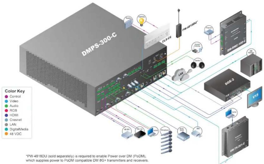
flowchart
graph TD
    A["DMPS-300-C"] --> B["CLS-C6"]
    B --> C["PW-4518DU*"]
    C --> D["DM-RNC-100-C"]
    D --> E["DGE-2"]
    E --> F["V15"]
    F --> G["DM-TX-201-C"]
    H["Control"] --> I["Video"]
    H --> J["Audio"]
    H --> K["RGB"]
    H --> L["HDMI"]
    H --> M["Cresnet"]
    H --> N["LAN"]
    H --> O["DigitalMedia"]
    H --> P["48 VDC"]
    style A fill:#999,stroke:#333
    style B fill:#999,stroke:#333
    style C fill:#999,stroke:#333
    style D fill:#999,stroke:#333
    style E fill:#999,stroke:#333
    style F fill:#999,stroke:#333
    style G fill:#999,stroke:#333
    style H fill:#999,stroke:#333
    style I fill:#ccc,stroke:#333
    style J fill:#ccc,stroke:#333
    style K fill:#ccc,stroke:#333
    style L fill:#ccc,stroke:#333
    style M fill:#ccc,stroke:#333
    style N fill:#ccc,stroke:#333
    style O fill:#ccc,stroke:#333
    style P fill:#ccc,stroke:#333
Residential DM-MD6X4 System
The example below shows a residential DM-MD6X4 system with:
- A2UrackmountDMmatrixswitcherthatincludes threeDM8G+outputsandone HDMloutput.
• ADM-RMC-100-C, toprovidevideo, audio, Ethernet, and controltoeachdisplay. - AnHD-XSPA, to serve as a DM receiver with full surround sound processing and amplifiers.
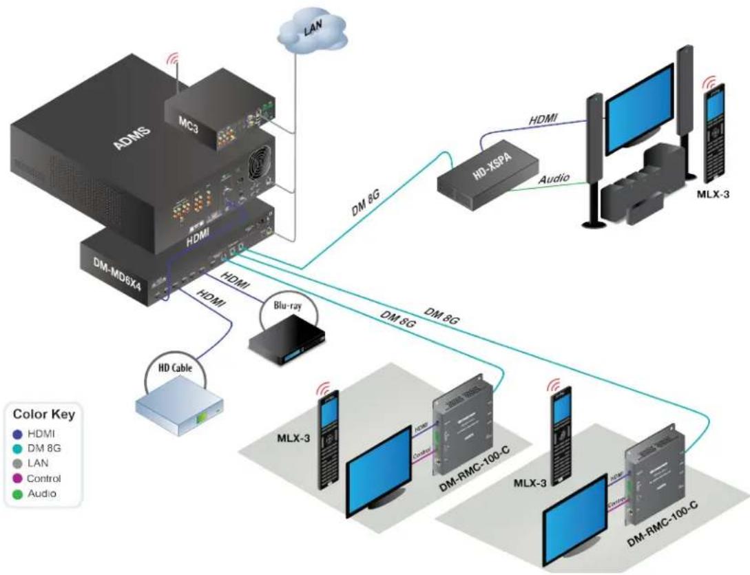
flowchart
graph TD
    A["ADMS"] -->|HDMI| B["MD6X4"]
    B -->|HDMI| C["HD Cable"]
    C --> D["Blu-ray"]
    D --> E["MD 8G"]
    E --> F["HD-XSPA"]
    F --> G["Audio"]
    G --> H["MLX-3"]
    H --> I["DM-RMC-100-C"]
    I --> J["Control"]
    J --> K["MD 8G"]
    K --> L["HD XSPA"]
    L --> M["MLX-3"]
    M --> N["DM-RMC-100-C"]
    N --> O["Control"]
    O --> P["MD 8G"]
    P --> Q["HD XSPA"]
    Q --> R["MLX-3"]
    R --> S["Control"]
    S --> T["MD 8G"]
    T --> U["HD XSPA"]
    U --> V["MLX-3"]
    V --> W["Control"]
    W --> X["MD 8G"]
    X --> Y["HD XSPA"]
    Y --> Z["MLX-3"]
    Z --> AA["Control"]
    AA --> AB["MD 8G"]
    AB --> AC["HD XSPA"]
Commercial VideoConference Room with DMPS-300-C-AEC
TheDMPS-300-C-AECintegrates thecontrolsystem.multimediamatrixswitcher,mic mixer withAcousticEchoCancellation(AEC),audioDSP,andamplifier.The DMPS-300-C-AECaffordsextensivesignalroutingflexibilityandhigh-performancesignal processing,andcanbeusedfor bothvideoandaudioconferencingwithouttheneedor an additionalmixer or processors.Theexamplebelowshows acommercialvideoconference roomusingaDMPS-300-C-AEC.
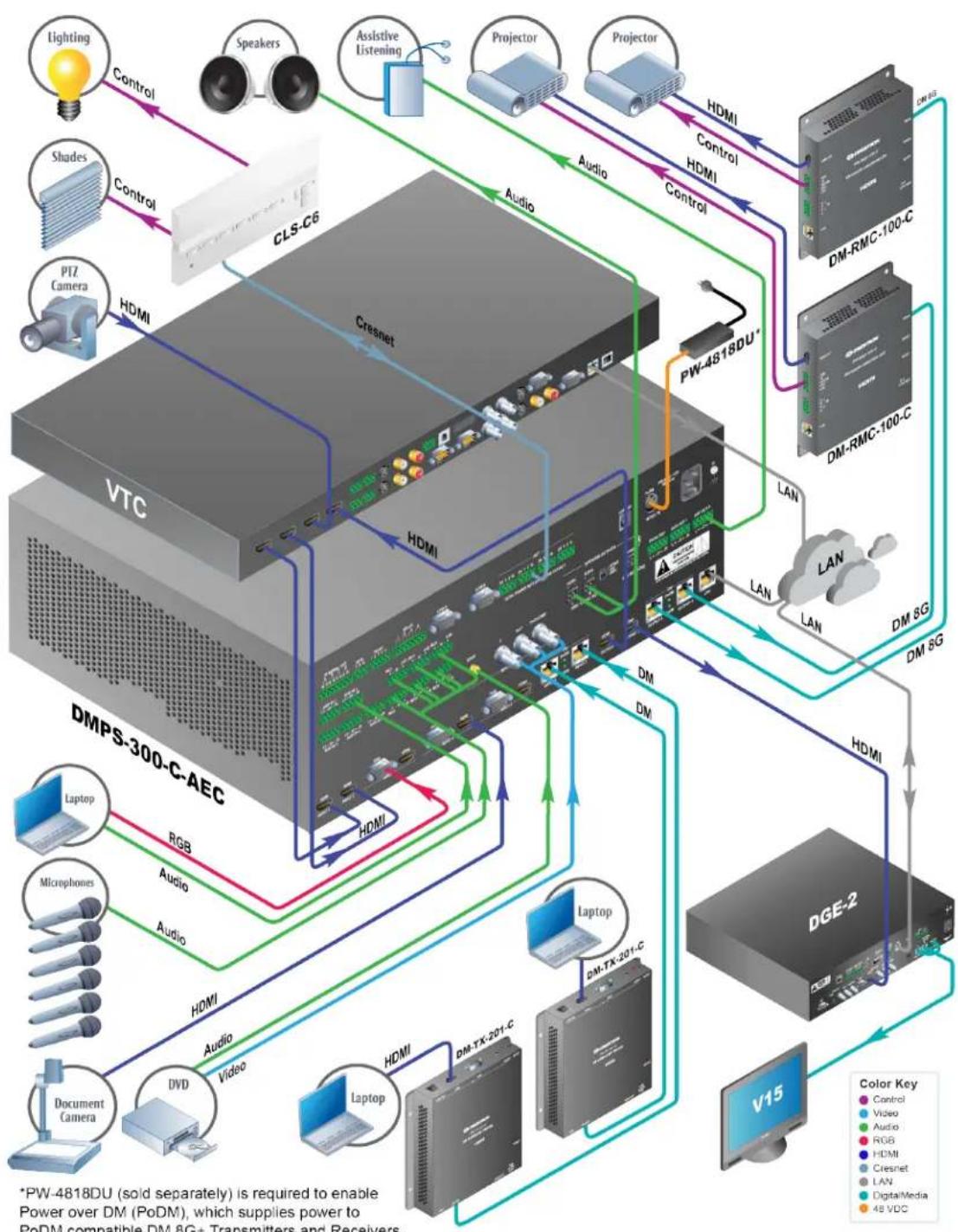
flowchart
graph TD
    subgraph VTC
        Lighting --> Control1["Control"]
        Speakers --> Control2["Control"]
        AssistiveListening --> Control3["Control"]
        Projector --> Control4["Control"]
        Projector --> Control5["Control"]
        Control3 --> CLS_C6
        Control4 --> CLS_C6
        Control5 --> CLS_C6
        CLS_C6 --> Cresnet
        PLZ_Camera --> HDMI
        HDMI --> VTC
    end

    subgraph DMPS-300-C-AEC
        VTC --> HDMI
        HDMI --> Audio
        Audio --> HDMI
        Audio --> HDMI
        HDMI --> Laptops
        Laptops --> RGB
        RGB --> Audio
        Audio --> Audio
        Audio --> HDMI
    end

    subgraph DGE-2
        DGE-2 --> V15
        V15 --> HDMI
        HDMI --> Audio
        Audio --> Audio
        Audio --> HDMI
        Audio --> Laptops
        Laptops --> DVD
        Laptops --> Document Camera
    end

    style VTC fill:#f9f,stroke:#333
    style DMPS-300-C-AEC fill:#ccf,stroke:#333
    style DGE-2 fill:#cfc,stroke:#333
    style V15 fill:#fcc,stroke:#333

    %% Legend:
    A["Color Key"]
    B["Power over DM (PoDM), which supplies power to PoDM compatible DM 8G+ Transmitters and Receivers."]
DMPS3-4K-150-Cwith a TT-100
The example below shows simple huddlespace with four CrestronConnectlable caddies coupled with a DMPS3-4K-150-C.
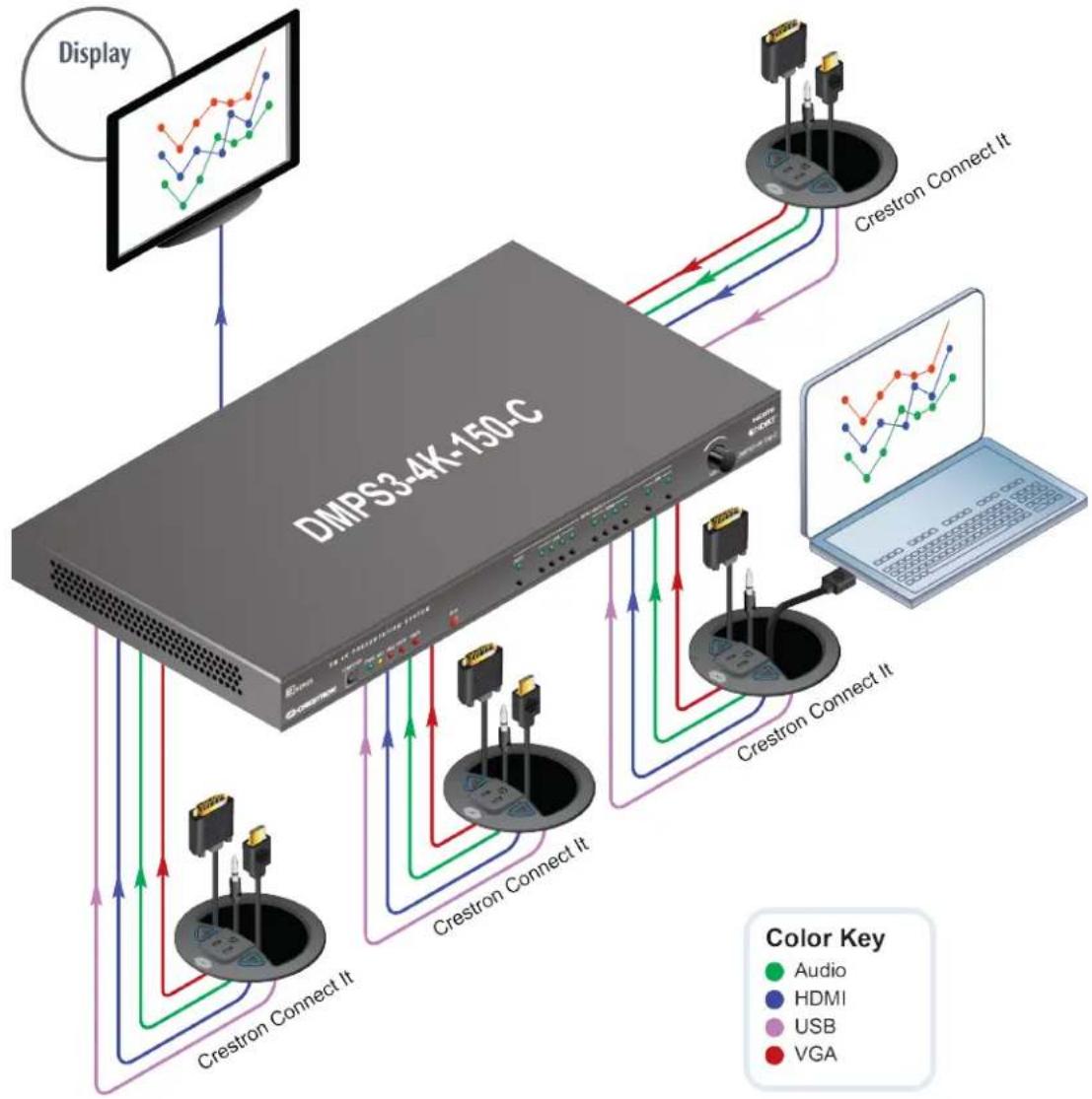
flowchart
graph TD
    A["Display"] --> B["DMPS3-4K-150-C"]
    B --> C["Crestron Connect It"]
    C --> D["Crestron Connect It"]
    D --> E["Crestron Connect It"]
    E --> F["Crestron Connect It"]
    F --> G["Crestron Connect It"]
    G --> H["Crestron Connect It"]
    H --> I["Crestron Connect It"]
    I --> J["Crestron Connect It"]
    J --> K["Crestron Connect It"]
    K --> L["Crestron Connect It"]
    L --> M["Crestron Connect It"]
    M --> N["Crestron Connect It"]
    N --> O["Crestron Connect It"]
    O --> P["Crestron Connect It"]
    P --> Q["Crestron Connect It"]
    Q --> R["Crestron Connect It"]
    R --> S["Crestron Connect It"]
    S --> T["Crestron Connect It"]
    T --> U["Crestron Connect It"]
    U --> V["Crestron Connect It"]
    V --> W["Crestron Connect It"]
    W --> X["Crestron Connect It"]
    X --> Y["Crestron Connect It"]
    Y --> Z["Crestron Connect It"]
    Z --> AA["Crestron Connect It"]
    AA --> AB["Crestron Connect It"]
    AB --> AC["Crestron Connect It"]
    AC --> AD["Crestron Connect It"]
    AD --> AE["Crestron Connect It"]
    AE --> AF["Crestron Connect It"]
    AF --> AG["Crestron Connect It"]
    AG --> AH["Crestron Connect It"]
    AH --> AI["Crestron Connect It"]
    AI --> AJ["Crestron Connect It"]
    AJ --> AK["Crestron Connect It"]
    AK --> AL["Crestron Connect It"]
    AL --> AM["Crestron Connect It"]
    AM --> AN["Crestron Connect It"]
    AN --> AO["Crestron Connect It"]
    AO --> AP["Crestron Connect It"]
    AP --> AQ["Crestron Connect It"]
    AQ --> AR["Crestron Connect It"]
    AR --> AS["Crestron Connect It"]
    AS --> AT["Crestron Connect It"]
    AT --> AU["Crestron Connect It"]
    AU --> AV["Crestron Connect It"]
    AV --> AW["Crestron Connect It"]
    AW --> AX["Crestron Connect It"]
    AX --> AY["Crestron Connect It"]
    AY --> AZ["Crestron Connect It"]
    AZ --> BA["Crestron Connect It"]
    BA --> BB["Crestron Connect It"]
    BB --> BC["Crestron Connect It"]
    BC --> BD["Crestron Connect It"]
    BD --> BE["Crestron Connect It"]
    BE --> BF["Crestron Connect It"]
    BF --> BG["Crestron Connect It"]
    BG --> BH["Crestron Connect It"]
    BH --> BI["Crestron Connect It"]
    BI --> BJ["Crestron Connect It"]
    BJ --> BK["Crestron Connect It"]
    BK --> BL["Crestron Connect It"]
    BL --> BM["Crestron Connect It"]
    BM --> BN["Crestron Connect It"]
    BN --> BO["Crestron Connect It"]
    BO --> BP["Crestron Connect It"]
    BP --> BQ["Crestron Connect It"]
    BQ --> BR["Crestron Connect It"]
    BR --> BS["Crestron Connect It"]
    BS --> BT["Crestron Connect It"]
    BT --> BU["Crestron Connect It"]
    BU --> BV["Crestron Connect It"]
    BV --> BW["Crestron Connect It"]
DMPS3-4K-150-C Basic Classroom
The example below shows abasic classroom system powered by a DMPS3-4K-150-C.
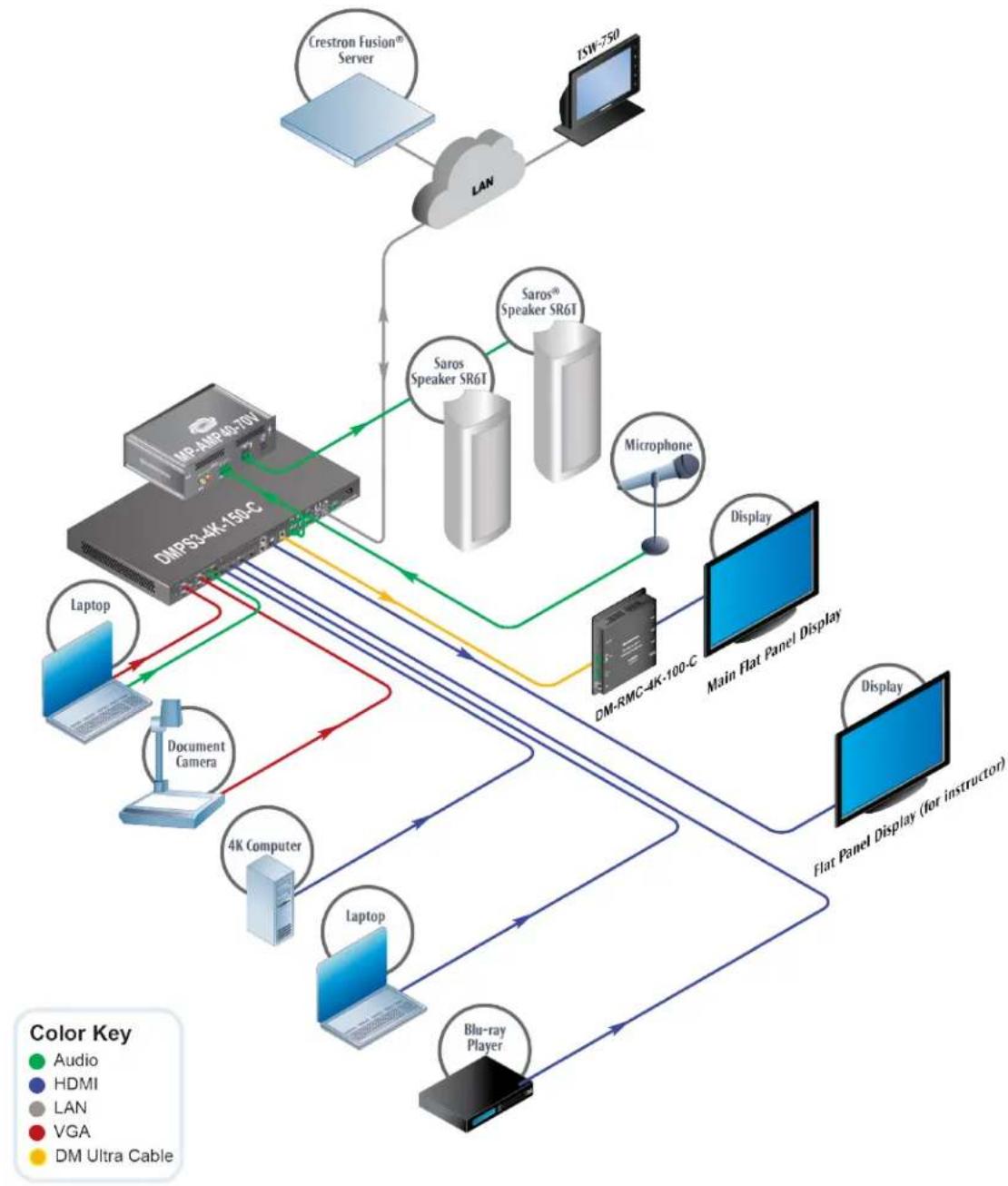
flowchart
graph TD
    A["Crestron Fusion® Server"] --> B["LAN"]
    B --> C["DSW-750"]
    C --> D["DMPS3-4K-150C"]
    D --> E["Saros® Speaker SR6T"]
    D --> F["Saros Speaker SR6T"]
    D --> G["Microphone"]
    D --> H["Laptop"]
    D --> I["Document Camera"]
    D --> J["4K Computer"]
    D --> K["Laptop"]
    D --> L["Blu-ray Player"]
    D --> M["Display"]
    M --> N["Main Flat Panel Display"]
    N --> O["Display"]
    O --> P["Flat Panel Display (for instructor)"]
    style A fill:#f9f,stroke:#333
    style C fill:#ccf,stroke:#333
    style D fill:#cfc,stroke:#333
    style E fill:#fcc,stroke:#333
    style F fill:#cff,stroke:#333
    style G fill:#ffc,stroke:#333
    style H fill:#fcc,stroke:#333
    style I fill:#fcc,stroke:#333
    style J fill:#fcc,stroke:#333
    style K fill:#fcc,stroke:#333
    style L fill:#fcc,stroke:#333
    style M fill:#fcc,stroke:#333
    style N fill:#ccf,stroke:#333
    style O fill:#ccf,stroke:#333
    style P fill:#ccf,stroke:#333
Digital Signage System
Digitalout-of-homeadvertisingandinformationsystems ,requiredynamichigh-resolution graphics,glitch-freeswitching,andastraightforwardtopology.CrestronDigitalMedia provides thebestmethodfor contentdeliveryinhigh-definition.Theexamplebelowshows adigitalsignagesystemwithmultisource,multidisplayHDMI distribution and long-distancecapabilityusingCresFiber.Thesourcecomputer is controlledviaaUSBHID connectiononanyDMreceiver.
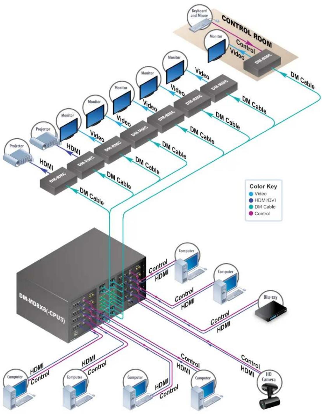
flowchart
graph TD
    subgraph Control Room
        A["Keyboard and Mouse"] --> B["Monitor"]
        B --> C["Video"]
        C --> D["DM-RMC"]
        D --> E["DM Cable"]
        E --> F["DM Cable"]
        F --> G["DM Cable"]
        G --> H["DM Cable"]
        H --> I["DM Cable"]
        I --> J["DM Cable"]
    end

    subgraph Control Room
        K["Keyboard and Mouse"] --> L["Monitor"]
        L --> M["Video"]
        M --> N["DM-RMC"]
        N --> O["DM Cable"]
        O --> P["DM Cable"]
        P --> Q["DM Cable"]
        Q --> R["DM Cable"]
        R --> S["DM Cable"]
        S --> T["DM Cable"]
    end

    subgraph Control Room
        U["Keyboard and Mouse"] --> V["Monitor"]
        V --> W["Video"]
        W --> X["DM-RMC"]
        X --> Y["DM Cable"]
        Y --> Z["DM Cable"]
        Z --> AA["DM Cable"]
        AA --> AB["DM Cable"]
        AB --> AC["DM Cable"]
    end

    subgraph Control Room
        AD["Keyboard and Mouse"] --> AE["Monitor"]
        AE --> AF["Video"]
        AF --> AG["DM-RMC"]
        AG --> AH["DM Cable"]
        AH --> AI["DM Cable"]
        AI --> AJ["DM Cable"]
        AJ --> AK["DM Cable"]
    end

    subgraph Control Room
        AL["Keyboard and Mouse"] --> AM["Monitor"]
        AM --> AN["Video"]
        AN --> AO["DM-RMC"]
        AO --> AP["DM Cable"]
        AP --> AQ["DM Cable"]
        AQ --> AR["DM Cable"]
    end

    subgraph Control Room
        AS["Keyboard and Mouse"] --> AT["Monitor"]
        AT --> AU["Video"]
        AU --> AV["DM-RMC"]
        AV --> AW["DM Cable"]
        AW --> AX["DM Cable"]
    end

    subgraph Control Room
        AY["Keyboard and Mouse"] --> AZ["Monitor"]
        AZ --> BA["Video"]
        BA --> BB["DM-RMC"]
        BB --> BC["DM Cable"]
    end

    subgraph Control Room
        BD["Keyboard and Mouse"] --> BE["Monitor"]
        BE --> BF["Video"]
        BF --> BG["DM-RMC"]
        BG --> BH["DM Cable"]
    end

    subgraph Control Room
        BI["Keyboard and Mouse"] --> BJ["Monitor"]
        BJ --> BK["Video"]
        BK --> BL["DM-RMC"]
        BL --> BM["DM Cable"]
    end

    subgraph Control Room
        BN["Keyboard and Mouse"] --> BO["Monitor"]
        BO --> BP["Video"]
        BP --> BQ["DM-RMC"]
        BQ --> BR["DM Cable"]
    end

    subgraph Control Room
        BS["Keyboard and Mouse"] --> BT["Monitor"]
        BT --> BU["Video"]
        BU --> BV["DM-RMC"]
        BV --> BW["DM Cable"]
    end

    subgraph Control Room
        BX["Keyboard and Mouse"] --> BY["Monitor"]
        BY --> BZ["Video"]
        BZ --> CA["DM-RMC"]
        CA --> CB["DM Cable"]
    end

    subgraph Control Room
        CC["Keyboard and Mouse"] --> DD["Monitor"]
        DD --> DE["Video"]
        DE --> DF["DM-RMC"]
        DF --> DG["DM Cable"]
    end

    subgraph Control Room
        DH["Keyboard and Mouse"] --> DI["Monitor"]
        DI --> DJ["Video"]
        DJ --> DK["DM-RMC"]
        DK --> DL["DM Cable"]
    end

    subgraph Control Room
        DJ --> DJ
    end

    style Control Room fill:#f9f,stroke:#333,stroke-width:2px
Multiwindow Processing and AnnotationwithDMSwitching
CrestronDM, combined with the DVPHD-GB videoprocessor, provides HD multiwindow processing, annotation, switching, and full DHCP support. The example below shows multiwindow processing and annotation using DM switching.
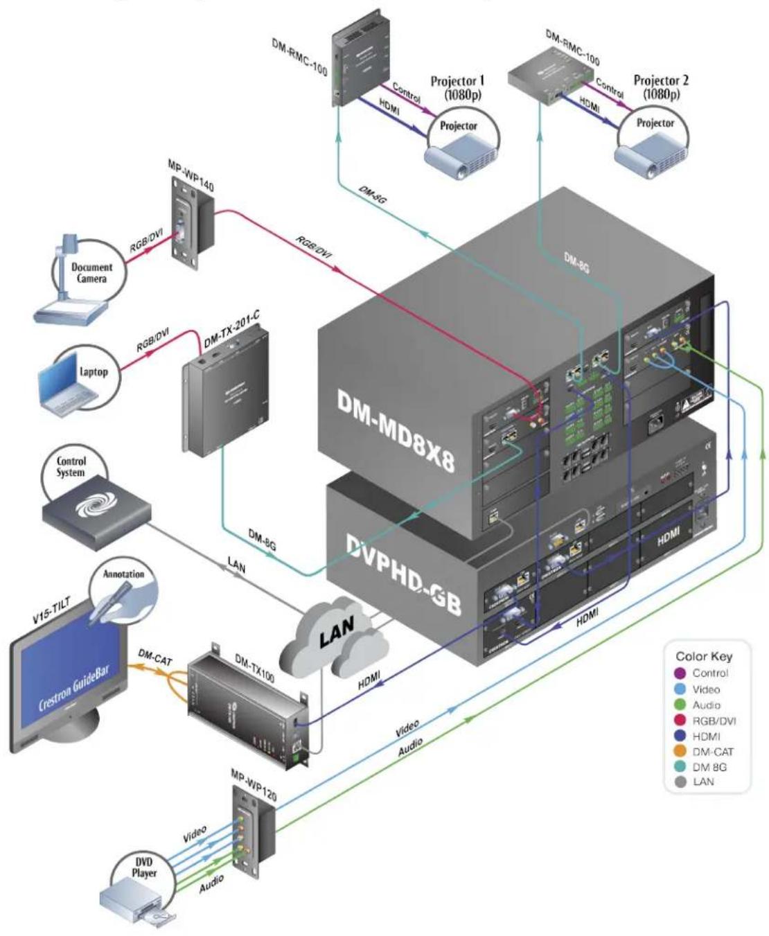
flowchart
graph TD
    subgraph_Module_1["DM-MD8X8"]
        A["Document Camera"] -->|RGB/DVI| B["MP-WP140"]
        C["Laptop"] -->|RGB/DVI| D["DM-TX-201-C"]
        E["Control System"] -->|LAN| F["DVPHD-GB"]
        G["V15-TILT"] --> H["Annotation"]
        I["Crestron GuideBar"] --> J["Video"]
        K["DVD Player"] --> L["MP-WP120"]
    end

    subgraph_Module_2["DM-MD8X8"]
        M["DM-RMC-100"] -->|Control HDMI| N["Projector 1 (1080p)"]
        O["DM-RMC-100"] -->|Control HDMI| P["Projector 2 (1080p)"]
        Q["DM-RMC-100"] -->|Control HDMI| R["Projector"]
    end

    subgraph_Module_3["DVPHD-GB"]
        S["DM-BG"] -->|LAN| T["Video"]
        U["Video"] --> V["Audio"]
    end

    Module_3 -->|DHMI| W["DM-BG"]
    Module_3 -->|HDMI| X["Video"]
    Module_3 -->|HDMI| Y["Audio"]
    Module_3 --> Z["DM-CAT"]
    Module_3 --> AA["DM-BG"]
    Module_3 --> AB["LAN"]

    subgraph_Module_4["DM-MD8X8"]
        AC["Document Camera"] --> AD["MP-WP140"]
        AE["Laptop"] --> AF["DM-TX-201-C"]
        AG["Control System"] --> AH["DVPHD-GB"]
        AI["V15-TILT"] --> AJ["Annotation"]
        AK["Crestron GuideBar"] --> AL["Video"]
        AM["DVD Player"] --> AN["MP-WP120"]
    end

    Module_4 -->|DHMI| AO["Video"]
    Module_4 -->|HDMI| AP["Audio"]
    Module_4 --> AQ["DM-CAT"]
    Module_4 --> AR["DM-BG"]
    Module_4 --> AS["LAN"]

    style Module_4 fill:#f9f,stroke:#333,stroke-width:2px
    style Module_4 fill:#ccf,stroke:#333,stroke-width:2px
    style Module_4 fill:#cfc,stroke:#333,stroke-width:2px
    style Module_4 fill:#fcc,stroke:#333,stroke-width:2px
    style Module_4 fill:#ffc,stroke:#333,stroke-width:2px
    style Module_4 fill:#fcc,stroke:#333,stroke-width:2px
    style Module_4 fill:#ffc,stroke:#333,stroke-width:2px
    style Module_4 fill:#fcc,stroke:#333,stroke-width:2px
    style Module_4 fill:#ffc,stroke:#333,stroke-width:2px
    style Segment_1 fill:#fff,stroke:#000
    style Segment_1 fill:#fff,stroke:#000
    style Segment_1 fill:#fff,stroke:#000
    style Segment_1 fill:#fff,stroke:#000
    style Segment_1 fill:#fff,stroke:#000
    style Segment_1 fill:#fff,stroke:#000
    style Segment_1 fill:#fff,stroke:#000
    style Segment_1 fill:#fff
    style Segment_1 fill:#fff,stroke:#000
    style Segment_1 fill:#fff,stroke:#000
    style Segment_1 fill:#fff,stroke:#000
    style Segment_1 fill:#fff,stroke:#000
    style Segment_1 fill:#fff,stroke:#000
    style Segment_1 fill:#fff,stroke:#000
    style Segment_1 fill:#fff,
    style Segment_1 fill:#fff,stroke:#000
    style Segment_1 fill:#fff,stroke:#000
    style Segment_1 fill:#fff,stroke:#000
    style Segment_1 fill:#fff,stroke:#000
    style Segment_1 fill:#fff,stroke:#000
    style Segment_1 fill:#fff,stroke:#000
    style Segment_1 fill:#fff, stroke:#000
    style Segment_1 fill:#fff,stroke:#000
    style Segment_1 fill:#fff,stroke:#000
    style Segment_1 fill:#fff,stroke:#000
    style Segment_1 fill:#fff,stroke:#000
    style Segment_1 fill:#fff,stroke:#000
    style Segment_1 fill:#fff,stroke:#000
    style Segment_2 fill:#fff,stroke:#000
    style Segment_2 fill:#fff,stroke:#000
    style Segment_2 fill:#fff,stroke:#000
    style Segment_2 fill:#fff,stroke:#000
    style Segment_2 fill:#fff,stroke:#000
    style Segment_2 fill:#fff,stroke:#000
    style Segment_2 fill:#fff,stroke:#000
Large-scaleSystem Using a DM-MD16X16(-CPU3)
The example below shows a large-scaled distributionsystem using a DM-MD16X16(-CPU3) with full audio and USB breakaway, and a / -space, 19-inchrack-mountable DM-MD16X16 (-CPU3) switcher.
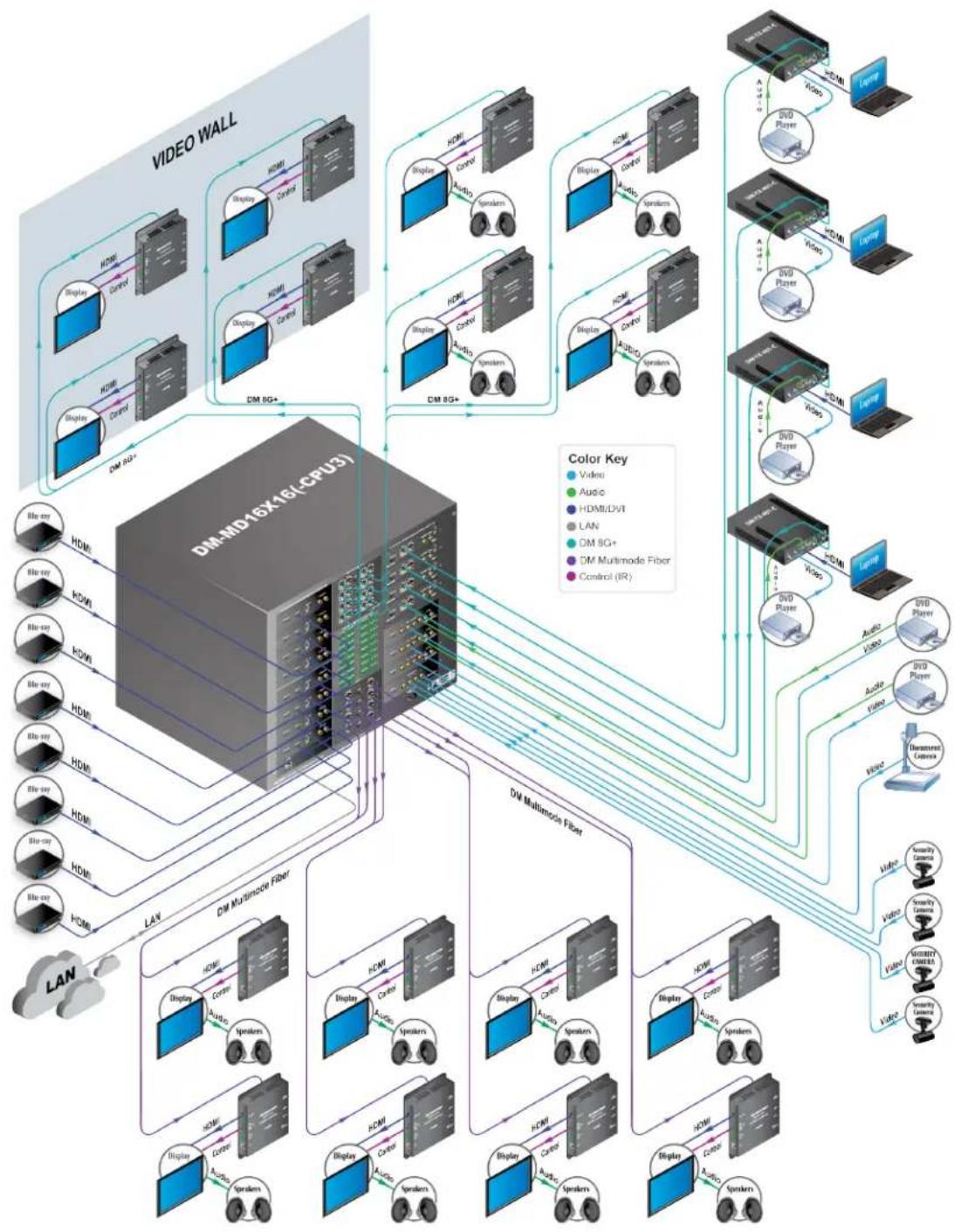
flowchart
graph TD
    A["VIDEO WALL"] --> B["DMI-MD16X16I-CPU3"]
    B --> C["Display"]
    B --> D["Control"]
    B --> E["HDMI"]
    B --> F["Control"]
    B --> G["Display"]
    B --> H["Control"]
    B --> I["HDMI"]
    B --> J["Control"]
    B --> K["Display"]
    B --> L["Control"]
    B --> M["HDMI"]
    B --> N["Control"]
    B --> O["Display"]
    B --> P["Control"]
    B --> Q["HDMI"]
    B --> R["Control"]
    B --> S["Display"]
    B --> T["Control"]
    B --> U["HDMI"]
    B --> V["Control"]
    B --> W["Display"]
    B --> X["Control"]
    B --> Y["HDMI"]
    B --> Z["Control"]
    B --> AA["Display"]
    B --> AB["Control"]
    B --> AC["HDMI"]
    B --> AD["Control"]
    B --> AE["Display"]
    B --> AF["Control"]
    B --> AG["HDMI"]
    B --> AH["Control"]
    B --> AI["Display"]
    B --> AJ["Control"]
    B --> AK["HDMI"]
    B --> AL["Control"]
    B --> AM["Display"]
    B --> AN["Control"]
    B --> AO["HDMI"]
    B --> AP["Control"]
    B --> AQ["Display"]
    B --> AR["Control"]
    B --> AS["HDMI"]
    B --> AT["Control"]
    B --> AU["Display"]
    B --> AV["Control"]
    B --> AW["HDMI"]
    B --> AX["Control"]
    B --> AY["Display"]
    B --> AZ["Control"]
    B --> BA["HDMI"]
    B --> BB["Control"]
    B --> BC["Display"]
    B --> BD["Control"]
    B --> BE["HDMI"]
    B --> BF["Control"]
    B --> BG["Display"]
    B --> BH["Control"]
    B --> BI["HDMI"]
    B --> BJ["Control"]
    B --> BK["Display"]
    B --> BL["Control"]
    B --> BM["HDMI"]
    B --> BN["Control"]
    B --> BO["Display"]
    B --> BP["Control"]
    B --> BQ["HDMI"]
    B --> BR["Control"]
    B --> BS["Display"]
    B --> BT["Control"]
    B --> BU["HDMI"]
    B --> BV["Control"]
    B --> BW["Display"]
    B --> BX["Control"]
    B --> BY["HDMI"]
    B --> BZ["Control"]
    B --> CA["Display"]
    B --> CB["Control"]
    B --> CC["HDMI"]
    B --> CD["Control"]
    B --> CE["Display"]
    B --> CF["Control"]
    B --> CG["HDMI"]
    B --> CH["Control"]
    B --> CI["Display"]
    B --> CJ["Control"]
    B --> CK["HDMI"]
    B --> CL["Control"]
    B --> CM["Display"]
    B --> CN["Control"]
    B --> CO["HDMI"]
    B --> CP["Control"]
    B --> CQ["Display"]
    B --> CR["Control"]
    B --> CS["HDMI"]
    B --> CT["Control"]
    B --> CU["Display"]
    B --> CV["Control"]
    B --> CW["HDMI"]
Large-scaleSystem Using a DM-MD64X64
The example below shows large-scaled distributions system with a DM-MD64X64. This system requires switchersystems with the flexibility and power to manage multiplesource and destination resolutions and HDCP keys.
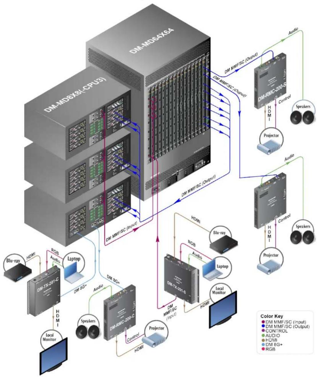
flowchart
graph TD
    A["DM-MD8X8 (CPU3)"] -->|HDMI| B["DM-TX-201-C"]
    A -->|RGB Audio| C["Laptop"]
    A -->|HDMI| D["Local Monitor"]
    A -->|Audio| E["DM 8G+"]
    E --> F["DM-RMC-200-C"]
    F --> G["DM 8G+"]
    G --> H["DM MMF/SC (Input)"]
    H --> I["DM MMF/SC (Output)"]
    I --> J["DM MMF/SC (Output)"]
    J --> K["DM MMF/SC (Output)"]
    K --> L["DM MMF/SC (Output)"]
    L --> M["DM MMF/SC (Output)"]
    M --> N["DM MMF/SC (Output)"]
    N --> O["DM MMF/SC (Output)"]
    O --> P["DM MMF/SC (Output)"]
    P --> Q["DM MMF/SC (Output)"]
    Q --> R["DM MMF/SC (Output)"]
    R --> S["DM MMF/SC (Output)"]
    S --> T["DM MMF/SC (Output)"]
    T --> U["DM MMF/SC (Output)"]
    U --> V["DM MMF/SC (Output)"]
    V --> W["DM MMF/SC (Output)"]
    W --> X["DM MMF/SC (Output)"]
    X --> Y["DM MMF/SC (Output)"]
    Y --> Z["DM MMF/SC (Output)"]
    Z --> AA["DM MMF/SC (Output)"]
    AA --> AB["DM MMF/SC (Output)"]
    AB --> AC["DM MMF/SC (Output)"]
    AC --> AD["DM MMF/SC (Output)"]
    AD --> AE["DM MMF/SC (Output)"]
    AE --> AF["DM MMF/SC (Output)"]
    AF --> AG["DM MMF/SC (Output)"]
    AG --> AH["DM MMF/SC (Output)"]
    AH --> AI["DM MMF/SC (Output)"]
    AI --> AJ["DM MMF/SC (Output)"]
    AJ --> AK["DM MMF/SC (Output)"]
    AK --> AL["DM MMF/SC (Output)"]
    AL --> AM["DM MMF/SC (Output)"]
    AM --> AN["DM MMF/SC (Output)"]
    AN --> AO["DM MMF/SC (Output)"]
    AO --> AP["DM MMF/SC (Output)"]
    AP --> AQ["DM MMF/SC (Output)"]
    AQ --> AR["DM MMF/SC (Output)"]
    AR --> AS["DM MMF/SC (Output)"]
    AS --> AT["DM MMF/SC (Output)"]
    AT --> AU["DM MMF/SC (Output)"]
    AU --> AV["DM MMF/SC (Output)"]
    AV --> AW["DM MMF/SC (Output)"]
    AW --> AX["DM MMF/SC (Output)"]
    AX --> AY["DM MMF/SC (Output)"]
    AY --> AZ["DM MMF/SC (Output)"]
    AZ --> BA["DM MMF/SC (Output)"]
    BA --> BB["DM MMF/SC (Output)"]
    BB --> BC["DM MMF/SC (Output)"]
    BC --> BD["DM MMF/SC (Output)"]
    BD --> BE["DM MMF/SC (Output)"]
    BE --> BF["DM MMF/SC (Output)"]
    BF --> BG["DM MMF/SC (Output)"]
    BG --> BH["DM MMF/SC (Output)"]
    BH --> BI["DM MMF/SC (Output)"]
    BI --> BJ["DM MMF/SC (Output)"]
    BJ --> BK["DM MMF/SC (Output)"]
    BK --> BL["DM MMF/SC (Output)"]
    BL --> BM["DM MMF/SC (Output)"]
    BM --> BN["DM MMF/SC (Output)"]
    BN --> BO["DM MMF/SC (Output)"]
    BO --> BP["DM MMF/SC (Output)"]
    BP --> BQ["DM MMF/SC (Output)"]
    BQ --> BR["DM MMF/SC (Output)"]
    BR --> BS["DM MMF/SC (Output)"]
    BS --> BT["DM MMF/SC (Output)"]
    BT --> BU["DM MMF/SC (Output)"]
    BU --> BV["DM MMF/SC (Output)"]
    BV --> BW["DM MMF/SC (Output)"]
    BW --> BX["DM MMF/SC (Output)"]
    BX --> BY["DM MMF/SC (Output)"]
    BY --> BZ["DM MMF/SC (Output)"]
    BZ --> CA["DM MMF/SC (Output)"]
    CA --> CB["DM MMF/SC (Output)"]
    CB --> CC["DM MMF/SC (Output)"]
    CC --> CD["DM MMF/SC (Output)"]
    CD --> CE["DM MMF/SC (Output)"]
    CE --> CF["DM MMF/SC (Output)"]
    CF --> CG["DM MMF/SC (Output)"]
    CG --> CH["DM MMF/SC (Output)"]
    CH --> CI["DM MMF/SC (Output)"]
    CI --> CJ["DM MMF/SC (Output)"]
    CJ --> CK["DM MMF/SC (Output)"]
    CK --> CL["DM MMF/SC (Output)"]
    CL --> CM["DM MMF/SC (Input)"]
    CM --> CN["Laptop"]
    CN --> CO["Laptop"]
    CO --> CP["Laptop"]
    CP --> CQ["Laptop"]
    CQ --> CR["Laptop"]
    CR --> CS["Laptop"]
    CS --> CT["Laptop"]
    CT --> CU["Laptop"]
    CU --> CV["Laptop"]
    CV --> CW["Laptop"]
    CW --> CX["Laptop"]
    CX --> CY["Laptop"]
    CY --> CZ["Laptop"]
    CZ --> DA["Laptop"]
    DA --> DB["Laptop"]
    DB --> DC["Laptop"]
    DC --> DD["Laptop"]
    DD --> DP["Laptop"]
    DP --> DP1["Laptop"]
    DP1 --> DP2["Laptop"]
    DP2 --> DP3["Laptop"]
    DP3 --> DP4["Laptop"]
    DP4 --> DP5["Laptop"]
    DP5 --> DP6["Laptop"]
    DP6 --> DP7["Laptop"]
    DP7 --> DP8["Laptop"]
    DP8 --> DP9["Laptop"]
    DP9 --> DP10["Laptop"]
    DP10 --> DP11["Laptop"]
    DP11 --> DP12["Laptop"]
    DP12 --> DP13["Laptop"]
    DP13 --> DP14["Laptop"]
    DP14 --> DP15["Laptop"]
    DP15 --> DP16["Laptop"]
    DP16 --> DP17["Laptop"]
    DP17 --> DP18["Laptop"]
    DP18 --> DP19["Laptop"]
    DP19 --> DP20["Laptop"]
    DP20 --> DP21["Laptop"]
    DP21 --> DP22["Laptop"]
    DP22 --> DP23["Laptop"]
    DP23 --> DP24["Laptop"]
    DP24 --> DP25["Laptop"]
    DP25 --> DP26["Laptop"]
    DP26 --> DP27["Laptop"]
    DP27 --> DP28["Laptop"]
    DP28 --> DP29["Laptop"]
    DP29 --> DP30["Laptop"]
    DP30 --> DP31["Laptop"]
    DP31 --> DP32["Laptop"]
    DP32 --> DP33["Laptop"]
    DP33 --> DP34["Laptop"]
    DP34 --> DP35["Laptop"]
    DP35 --> DP36["Laptop"]
    DP36 --> DP37["Laptop"]
    DP37 --> DP38["Laptop"]
    DP38 --> DP39["Laptop"]
    DP39 --> DP40["Laptop"]
    DP40 --> DP41["Laptop"]
    DP41 --> DP42["Laptop"]
    DP42 --> DP43["Laptop"]
    DP43 --> DP44["Laptop"]
    DP44 --> DP45["Laptop"]
    DP45 --> DP46["Laptop"]
    DP46 --> DP47["Laptop"]
    DP47 --> DP48["Laptop"]
    DP48 --> DP49["Laptop"]
    DP49 --> DP50["Laptop"]
    DP50 --> DP51["Laptop"]
    DP51 --> DP52["Laptop"]
    DP52 --> DP53["Laptop"]
    DP53 --> DP54["Laptop"]
    DP54 --> DP55["Laptop"]
Low-costClassroom Using DM8G+
The example below shows alow-cost classroom using DM8G+with the following:
- LaptopandBlu-raysourceslocatedatthepodium(localmonitor candisplayeither source).
- AsingleDM8G+cableruns from thepodiumtotheroomcontroller located by the projector.
- The projector connects via HDMI and abuilt-in, 30-watt amplifier powers the speakers in the room.
. The control system is connected via Ethernet.
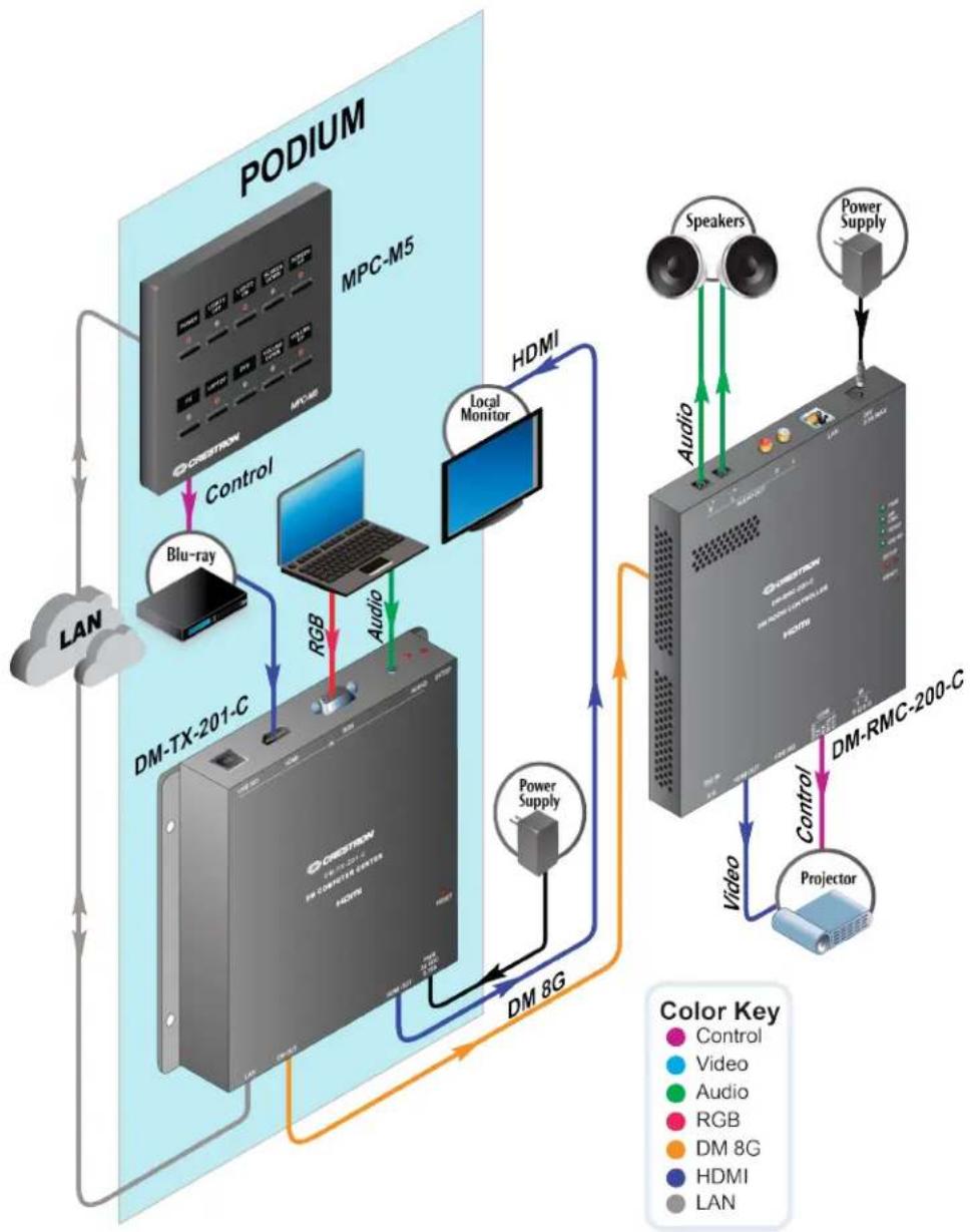
flowchart
graph TD
    A["PODIUM"] -->|Control| B["DM-TX-201-C"]
    A -->|Audio| C["Local Monitor"]
    A -->|Audio| D["Power Supply"]
    A -->|Audio| E["Video"]
    A -->|Audio| F["DM-8G"]
    A -->|Audio| G["DM-RMC-200-C"]
    H["LAN"] --> A
    I["ChINA"] --> A
    J["MPC-M5"] --> A
    K["Blu-ray"] --> A
    L["RGB"] --> A
    M["HDMI"] --> A
    N["Speaker"] --> A
    O["Power Supply"] --> A
    P["Projector"] --> A
    Q["Color Key"] --> A
    R["Color Key"] --> A
Powerful Boardroom Using DM 8G and DMCAT
The example below shows aboardroom using DM8G and DMCAT.
- TheDM-MD8X8(-CPU3)connects tothecontrolsystemviaEthernetandtothewall plates viaDigitalMediaCAT.
- Thetworoomcontrollersandtwocomputer centers connecttotheDM-MD8X8 (-CPU3)viaDigitalMedia8GSTP.
- Thefirstroomcontroller(DM-RMC-100-C)sendsvideototheprojector viaHDMI.
- Thesecondroomcontroller (DM-RMC-200-C) sends video to a monitor via HDMI, connects the USB keyboard and mouse, and controls the Blu-ray player via R.
- Thecomputercenter (DM-TX-201-C)atthepodiumsends Blu-rayaudioandvideoto theDM-MD8X8(-CPU3).
- Thecomputercenter (DM-TX-201-C)attheconferencetablesends,audioandvideo fromthelaptoptotheDM-MD8X8(-CPU3),andmirrors thelaptopdisplayonalocal monitor.
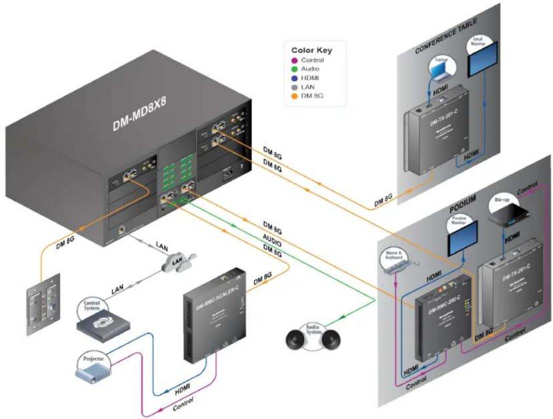
flowchart
graph TD
    A["DM-MD8X6"] -->|LAN| B["DM-200C-SEALER-C"]
    A -->|LAN| C["DM-200C-SEALER-C"]
    A -->|LAN| D["DM-200C-SEALER-C"]
    A -->|LAN| E["DM-200C-SEALER-C"]
    A -->|LAN| F["DM-200C-SEALER-C"]
    A -->|LAN| G["DM-200C-SEALER-C"]
    A -->|LAN| H["DM-200C-SEALER-C"]
    A -->|LAN| I["DM-200C-SEALER-C"]
    A -->|LAN| J["DM-200C-SEALER-C"]
    A -->|LAN| K["DM-200C-SEALER-C"]
    A -->|LAN| L["DM-200C-SEALER-C"]
    A -->|LAN| M["DM-200C-SEALER-C"]
    A -->|LAN| N["DM-200C-SEALER-C"]
    A -->|LAN| O["DM-200C-SEALER-C"]
    A -->|LAN| P["DM-200C-SEALER-C"]
    A -->|LAN| Q["DM-200C-SEALER-C"]
    A -->|LAN| R["DM-200C-SEALER-C"]
    A -->|LAN| S["DM-200C-SEALER-C"]
    A -->|LAN| T["DM-200C-SEALER-C"]
    A -->|LAN| U["DM-200C-SEALER-C"]
    A -->|LAN| V["DM-200C-SEALER-C"]
    A -->|LAN| W["DM-200C-SEALER-C"]
    A -->|LAN| X["DM-200C-SEALER-C"]
    A -->|LAN| Y["DM-200C-SEALER-C"]
    A -->|LAN| Z["DM-200C-SEALER-C"]
    A -->|LAN| AA["DM-200C-SEALER-C"]
    A -->|LAN| AB["DM-200C-SEALER-C"]
    A -->|LAN| AC["DM-200C-SEALER-C"]
    A -->|LAN| AD["DM-200C-SEALER-C"]
    A -->|LAN| AE["DM-200C-SEALER-C"]
    A -->|LAN| AF["DM-200C-SEALER-C"]
    A -->|LAN| AG["DM-200C-SEALER-C"]
    A -->|LAN| AH["DM-200C-SEALER-C"]
    A -->|LAN| AI["DM-200C-SEALER-C"]
    A -->|LAN| AJ["DM-200C-SEALER-C"]
    A -->|LAN| AK["DM-200C-SEALER-C"]
    A -->|LAN| AL["DM-200C-SEALER-C"]
    A -->|LAN| AM["DM-200C-SEALER-C"]
    A -->|LAN| AN["DM-200C-SEALER-C"]
    A -->|LAN| AO["DM-200C-SEALER-C"]
    A -->|LAN| AP["DM-200C-SEALER-C"]
    A -->|LAN| AQ["DM-200C-SEALER-C"]
    A -->|LAN| AR["DM-200C-SEALER-C"]
    A -->|LAN| AS["DM-200C-SEALER-C"]
    A -->|LAN| AT["DM-200C-SEALER-C"]
    A -->|LAN| AU["DM-200C-SEALER-C"]
    A -->|LAN| AV["DM-200C-SEALER-C"]
    A -->|LAN| AW["DM-200C-SEALER-C"]
    A -->|LAN| AX["DM-200C-SEALER-C"]
    A -->|LAN| AY["DM-200C-SEALER-C"]
    A -->|LAN| AZ["DM-200C-SEALER-C"]
    A -->|LAN| BA["DM-200C-SEALER-C"]
    A -->|LAN| BB["DM-200C-SEALER-C"]
    A -->|LAN| BC["DM-200C-SEALER-C"]
    A -->|LAN| BD["DM-200C-SEALER-C"]
    A -->|LAN| BE["DM-200C-SEALER-C"]
    A -->|LAN| BF["DM-200C-SEALER-C"]
    A -->|LAN| BG["DM-200C-SEALER-C"]
    A -->|LAN| BH["DM-200C-SEALER-C"]
    A -->|LAN| BI["DM-200C-SEALER-C"]
    A -->|LAN| BJ["DM-200C-SEALER-C"]
    A -->|LAN| BK["DM-200C-SEALER-C"]
    A -->|LAN| BL["DM-200C-SEALER-C"]
    A -->|LAN| BM["DM-200C-SEALER-C"]
    A -->|LAN| BN["DM-200C-SEALER-C"]
    A -->|LAN| BO["DM-200C-SEALER-C"]
    A -->|LAN| BP["DM-200C-SEALER-C"]
    A -->|LAN| BQ["DM-200C-SEALER-C"]
    A -->|LAN| BR["DM-200C-SEALER-C"]
    A -->|LAN| BS["DM-200C-SEALER-C"]
    A -->|LAN| BT["DM-200C-SEALER-C"]
    A -->|LAN| BU["DM-200C-SEALER-C"]
    A -->|LAN| BV["DM-200C-SEALER-C"]
    A -->|LAN| BW["DM-200C-SEALER-C"]
    A -->|LAN| BX["DM-200C-SEALER-C"]
    A -->|LAN| BY["DM-200C-SEALER-C"]
    A -->|LAN| BZ["DM-200C-SEALER-C"]
    A -->|LAN| CA["DM-200C-SEALER-C"]
    A -->|LAN| CB["DM-200C-SEALER-C"]
    A -->|LAN| CC["DM-200C-SEALER-C"]
    A -->|LAN| CD["DM-200C-SEALER-C"]
    A -->|LAN| CE["DM-200C-SEALER-C"]
    A -->|LAN| CF["DM-200C-SEALER-C"]
    A -->|LAN| CG["DM-200C-SEALER-C"]
    A -->|LAN| CH["DM-200C-SEALER-C"]
    A -->|LAN| CI["DM-200C-SEALER-C"]
    A -->|LAN| CJ["DM-200C-SEALER-C"]
    A -->|LAN| CK["DM-200C-SEALER-C"]
DM-TX-401-C BYOD with Crestron Connect It
The example below shows asimple, low-costpoint-to-point HID AV presentations solution with a BYOD (bring your own device) source.
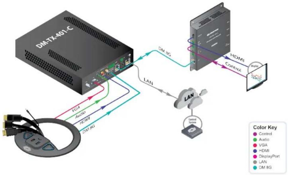
flowchart
graph TD
    A["DM-TX-401-C"] -->|VGA Audio HDMI DM 8G| B["LAN"]
    A -->|VGA Audio HDMI DM 8G| C["Control System"]
    B --> D["DM 8G"]
    D --> E["Control"]
    E --> F["Display"]
    style A fill:#f9f,stroke:#333
    style B fill:#ccf,stroke:#333
    style C fill:#cfc,stroke:#333
    style D fill:#fcc,stroke:#333
    style E fill:#cff,stroke:#333
    style F fill:#ffc,stroke:#333
DM-TX-401-C with Installed Sources
The example below shows asimple, low-costpoint-to-point HID AV presentations solution with installed sources.
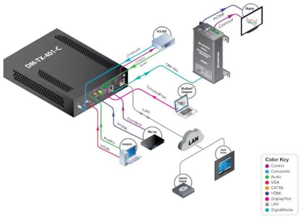
flowchart
graph TD
    A["DM-TK-401-C"] -->|Control| B["Host"]
    A -->|Audio| C["Computer"]
    A -->|VGA| D["Monitor"]
    B -->|DisplayPort| E["MacBank Computer"]
    B -->|LAN| F["LAN"]
    C -->|Control| G["DisplayPort"]
    C -->|Audio| H["Monitor"]
    C -->|VGA| I["Monitor"]
    D -->|Control| J["DisplayPort"]
    D -->|Audio| K["Monitor"]
    D -->|VGA| L["Monitor"]
    E --> M["DisplayPort"]
    F --> N["Control System"]
    F --> O["Touch System"]
    G --> P["Control System"]
    H --> Q["Control System"]
    I --> R["Control System"]
    J --> S["Control System"]
    K --> T["Control System"]
    L --> U["Control System"]
    M --> V["DisplayPort"]
    N --> W["DisplayPort"]
    O --> X["DisplayPort"]
    P --> Y["DisplayPort"]
    Q --> Z["DisplayPort"]
    R --> AA["DisplayPort"]
    S --> AB["DisplayPort"]
    T --> AC["DisplayPort"]
    U --> AD["DisplayPort"]
    V --> AE["DisplayPort"]
    W --> AF["DisplayPort"]
    X --> AG["DisplayPort"]
    Y --> AH["DisplayPort"]
    Z --> AI["DisplayPort"]
AppendixD:AnIn-depthLook at HDMI
DM4KZtechnologyemploysVESA®DisplayStreamCompression(DSC),enhancingthe capabilities of DigitalMediatohandletheextremebandwidthrequirements of resolutions beyond4K304:4:4 and4K604:2:0.DSCis alightweight,line-based,2:1compression standardthatdelivers virtuallylossless performancefor 4K604:4:4 andHDRsignals.DSC isappliedonlyto4K604:4:4 andHDRinputsignals.Allothersignals aretransported uncompressed.
RequiredDataRates withHDMIOverhead
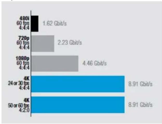
bar
| Category | Value (Gbit/s) | |---|---| | 480i 60 fps 4:4:4 | 1.62 | | 720p 60 fps 4:4:4 | 2.23 | | 1080p 60 fps 4:4:4 | 4.46 | | 4K 24 or 30 fps 4:4:4 | 8.91 | | 4K 50 or 60 fps 4:2:0 | 8.91 |CompareAnalog and HDMICables
AnalogCable HDMICable
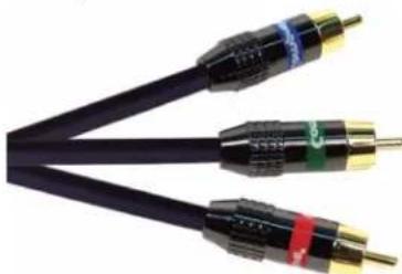
natural_image
Close-up of a black and gold audio/video cable with three connectors (no text or symbols visible)- Separateaudioandvideocables
. Robustsignals
• Fieldtermination
• Inexpensive
• Installer friendly
. Reliable multiroóm distribution
. Distanceis rarelyanissue
. Nocopyprotección(DRM)support
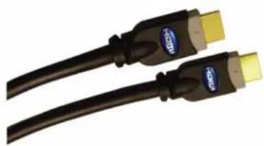
natural_image
Two black USB cable connectors with yellow connectors, shown side by side (no text or symbols visible)- SingleAVcable
. Delicatesignals
. Cannotbefieldterminated
. Veryexpensive
. Difficulttorun
. Unreliablemultiroomsolution
• Limiteddistance
. Supports copyprotection
ThecomplexityofHDMI becomes obviouswhenHDMI cables arecompared to analog audio and videocables. Analog cables typically consist of one to three wire repairs, depending on the format, and they simply carry an audio or video signal (not both). In contrast, the HDMI cable consists of 19 wires that carry high-speed video, audio, and other digital information. The digital audio and video data is encoded into three color channels and clock channel. Audio is embedded inside the video data and is inserted and extracted at each end. Additional information carried by HDMI includes:
- TheDataDisplaychannel(DDC),a2-waycommunicationsinterfacebetweenthe sourceandthedownstreamrepeater ordisplaydevice.Thischannelwas originally providedtocommunicatedevicecapabilityinformation,whichis encodedinEDID.HDMldevices .useEDIDtoindicatewhataudioandvideoformats theysupport.The DDCinterfaceisalsousedtosetupandmaintainHDCPencryption.
- Thedownstream device, or sink, indicates its presencetothesourcewiththehot plugdetect(HPD)signal, which allows each device to know when acable has been connected and start authentication.
- Consumer Electronics. Control(CEC), a function that provides control to multiple devices over HDMI using one remote control device. A secondary device receives commands from a primary device. Although CEC wiring is required for every HDMI port, this does not mean every HDMI porthast the function enabled.
Depending on the device and manufacturer, DDC, HPD, and CEC signals interact differently. This inconsistency can negatively affect device performance. There are additional controls signals associated with HDMI, but they are beyond the scope of this guide.
Topology
EveryHDMI_installationconsists of atleastonecontentsource,likeacableboxor Blu-ray player,andaTVor aprojector.Mostcustom installations alsoinvolveatleastonerepeater,adevicethatacepts.andretransmits_HDMI content.Repeaters includesimpledevices suchasswitchesanddistributionamplifiers as wellasmorefeature-richdevices suchas audioandvideoprocessors.
EDID
HDMI displaydevices_andsurroundsoundreceivers_useEDID_tocommunicatetheiraudioandvideocapabilities_EmbeddedintheHDMI_signal,EDID_dataisgeneratedbyadisplayoraudioprocessortoinform_theupstream_sourceaboutits_formatandresolutioncapabilities.Inresponsetothisdata,thesourceordinarilyconfiguresitselftosendthebestvideoresolutionandaudioformatthatbothdevices cansupport.For example,Blu-rayplayers_includevideoscalers_tobestmatchthedisc's nativeformattothecapabilities ofthelevisionorprojector.
In the simplest installations with onetelevision and a audioprocessor, the EDID protocol works reasonably well. Multi room installations can quickly become problematic when several televisions are connected to several sources throughout or more HDMI switches. Neither the HDMI nor the EDID specificationsoffer assistance to the user.
SeeEDID Designfor moreinformation.
HDCP
High-bandwidthDigitalContentProtection(HDCP)isanecryptionschemethatcontent providers, usetoprotecttheir DVDs, Blu-raydiscs, andbroadcastsignals against unauthorizedcopying.HDCPmanagementensuresthatprotectedcontentcannot be distributedviastreaming.TheHDCPsystem:
- AuthenticatesHDCPdevices toensuretheyarelicensedandauthorizedtoreceive thecontent.Onlyaftersuccessfulauthenticationwillthedisplaybeabletooutput theaudioandvideostreams.
- Encrypts thecontenttopreventinterceptionduringtransmission.
HDCP Authenticates EachDevice via the Source
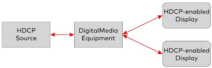
flowchart
graph LR
    A["HDCP Source"] <--> B["DigitalMedia Equipment"]
    B --> C["HDCP-enabled Display"]
    B --> D["HDCP-enabled Display"]
HDCPEncryptsEachIndividual Segmentof an AVTransmission
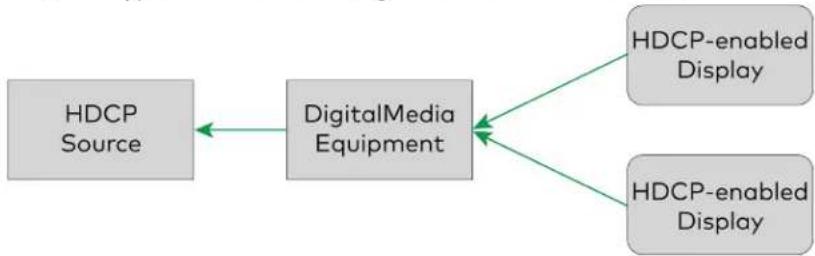
flowchart
graph LR
    A["HDCP Source"] --> B["DigitalMedia Equipment"]
    B --> C["HDCP-enabled Display"]
    B --> D["HDCP-enabled Display"]
Devices. thatretransmitHDCPcontentmustinformthesourceofallthedownstream connections inthesystem.EveryHDCPdevicehas auniqueD,knowas qKeySelection Vector. (KSV),thatmustbepassedtothesource.Thesourcemustthenverifyeachdevice beforeittransmits content.Itis this authenticationprocess thatcauses theswitchtime delayinHDMI devices.
DigitalMediasolves theblankscreenissuebyutilizingatechnologycalledQuickSwitchHD. QuickSwitchHD manages thekeys for everyHDCP-compliantdeviceinthesystem, maintainingcontinuous authenticationfor eachdevicetoensurerast,reliableroutingof anysourcetoanynumber of displaydevices.InqstandardHDMIswitcher,eachdisplayis authenticateddynamicallywhenvideos routed.WithDigitalMedia,theauthentication process takes placeasdisplays areadded.Duringinitialization,sources areauthenticated witheachdisplaythroughtheDMsystembeforeanyaudioor videos routed.
Crestron's High-DefinitionDigitalVideoProcessor (DVPHD)isthefirstmultiwindow processor of its kindthatenables HDCPtoworkwithacompleteangeof_digitalvideo players,cableandsatellitereceivers,multimediacomputers,displays,andprojectors,While other,manufacturers ignoreHDCPcompletely,theDVPHD actuallyperforms advanced HDCPsignalmanagement,allowinguptoeightHDCP-encryptedsourcestobecombined ononehigh-definitionscreen.
Consumer Electronics Control
EachHDMI cablecontains acommunicationlinkthatenables devices connectedviaHDMI totalktoeachother.Thisprotocolis calledConsumerElectronics Control(CEC).When a controlsystem isinplace,theother devicesshouldnotissuecommands.CECissupposed tocontainindustry-standardcommands. for interoperability,butinconsistentsupport from CEmanufacturers hascausedawidevariationinthefunctionsthatcanbetriggered from eachdevice.Someexamples of thisfunctionalitythatCrestronhasdiscoveredare:
- MultipleDVDplayers from thesamemanufacturerinthesamesystem communicate with the chothers that only one can play at time. Every time one player is issued the play command, the player sends apause command to the other players via CEC.
- WhenaBlu-rayplayeris, turnedoff, itsendsapoweroffcommand, turningoffall displays connectedtothesystem.
Thesefunctionalcommands are major issue because they are present behind the scenes. Digital Mediabreaks the communication path between the HDMI devices that are connected to the switch. Therefore, these commands cannot be sent without approval.
DigitalMediaprovidesamethodtoissueCECcommands from acontrolsystem sothe communicationlinkcanbesuedas analternativetoRandRS-232control
Audio
HDMI, providestheonlytransmissionlinkfor 7.1-channelHD audio.However,unlike traditionalanalogvideosources,HDMI sourcesusuallydonottransmitmultichanneland 2-channelaudioathesametime.This becomesaproblemfor multiroom distributionin whichamixtureofsurroundsoundandstereoaudjorooms arepresent.HDMI sources oftenshutoff analogoutputswhensendingaudioviaHDMI. DigitalMediasolvesthisproblem byafferingspecialHDMI, cardsthattakeinamultichannel audiostreamandoutputbothtypesof audiofor distribution.Thesespecialcards are notedbya-DSP suffix. AudioDistributionExample
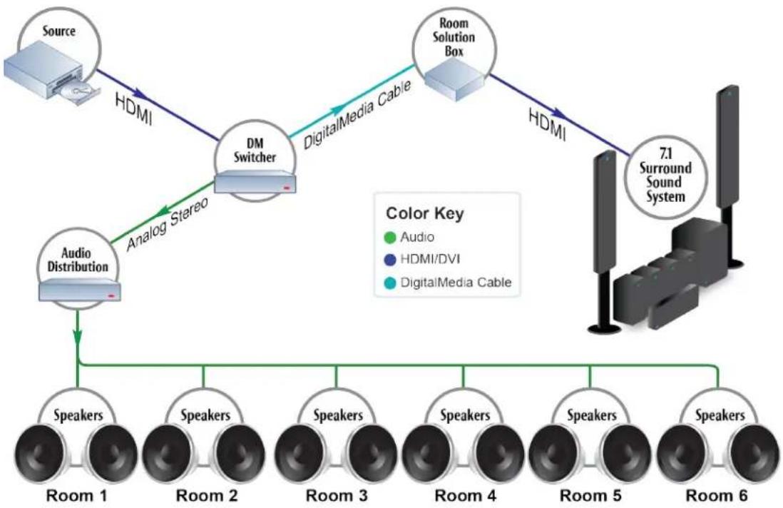
flowchart
graph TD
    A["Source"] -->|HDMI| B["DM Switcher"]
    B -->|DigitalMedia Cable| C["Room Solution Box"]
    C -->|HDMI| D["7.1 Surround Sound System"]
    E["Audio Distribution"] -->|Analog Stereo| B
    F["Room 1"] --> G["Speakers"]
    H["Room 2"] --> I["Speakers"]
    J["Room 3"] --> K["Speakers"]
    L["Room 4"] --> M["Speakers"]
    N["Room 5"] --> O["Speakers"]
    P["Room 6"] --> Q["Speakers"]
    style A fill:#f9f,stroke:#333
    style B fill:#ccf,stroke:#333
    style C fill:#cfc,stroke:#333
    style D fill:#fcc,stroke:#333
    style E fill:#cff,stroke:#333
    style F fill:#ffc,stroke:#333
    style G fill:#cfc,stroke:#333
    style H fill:#cfc,stroke:#333
    style I fill:#cfc,stroke:#333
    style J fill:#cfc,stroke:#333
    style K fill:#cfc,stroke:#333
    style L fill:#cfc,stroke:#333
    style M fill:#cfc,stroke:#333
    style N fill:#cfc,stroke:#333
    style O fill:#cfc,stroke:#333
    style P fill:#cfc,stroke:#333
Convergence
HDMlenablescomputers, todeliverpremiummediacontent,includinghigh-definition movies andmultichannelaudioformats.Itis theonlyinterfacethenables direct connections tobothHDTVsanddigitalcomputermonitorswhileupholdingtheDVland HDMlstandards.
HDMI is fully compatible with all DVI-enabled computers because HDMI was developed using the ametechnology as Digital Visual Interface (DVI), which has been the most common digital connection for computers. Because HDMI offers both audio and video over one cable and DVI only carries video, DVI and HDMI connectivity requires a separate audio cable.
DisplayPort
DisplayPortisaVESA(VideoElectronics Standards Association)standardfor digitalvideo connectionandis similar toHDMinfunctionality.TheDisplayPortstandardwasdrivenby thePCindustrytoachievealow-costprocess for transferringvideofrom acomputer toa laptopscreenandexternaldigitalvideooutput.Bothprotocols's support1080pandhigher resolutions,HDCPcontentprotectionandmultichannelaudio.HDMI additionallysupports someitems notsupportedbyDisplayPort,suchas CEC.
Summary
Widesupportfrom contentproviders andtheconsumerelectronics marketplacemakes HDM|thecurrentstandardofHD,videotransmission.Therearemanyproblems with.
HDM and they are not just limited to a cable length issues. Processing EDID and managing HDCP requires complex microcontrollers, especially when several rooms are involved. Switching systems must be easily customizable to intelligently handle EDID and HDCP.
DigitalMediamanages thesevarious communicationmechanisms andprovidesextensive troubleshootinginformationsotheinstaller cansolveissues suchas cablefailure,device incompatibilities,andcontentprotectioncomplications.
Glossary
4K: Aclass of resolutions of approximately 4000x2000 pixels.
4KUltraHD(UHD):UHDhasaresolutionof3840x2160andprovides twotimes more horizontalandverticalresolutionthanthe1080phigh-definitiontelevision(HDTV)format.
4KZ:4KZhasaresolutionof3840x2160pixels ata60Hzframeratewith4:4:4 color samplingandhighdynamicrange(HDR)videosignals.
480i:Aform of standard-definitiontelevision(SDTV)withaverticalresolutionof480 interlaced(non-progressive)lines.
480p:Aform of standard-definitiontelevision(SDTV)withaverticalresolutionof480 progressive(non-interlaced)lines.
720p:This formatis consideredstandardHDandhasaresolutionof1280x720.Itis a progressivescanformat.
1080i:Thisformatis consideredFullHD andhas aresolutionof1920x 1080.Itisan interlacedformat.
1080p:Thisformatis consideredFullHD andhasaresolutionof1920x1080.Itis an progressiveformat.
Anamorphicwidescreen:Aprocess ofhorizontallycompressingwidescreenimages intoa 4:3televisionsignal.Compatibleplaybackequipmentcahexpandithorizontallytorestore theoriginalwidescreenimage.Widescreenimagesthatarenotanamorphic arenotas detailedwhentheyareshownonawidescreendisplay.
AspectRatio:Theratioofwidthtoheightingvideoimage(referringtotheshapeofa screenor program).HDTVhasa16 x9 ratio.Standardtelevisionhas a4:3ratio.
Authentication: A process that verifiestheuser's credentials to confirm their identity for access rights.
ComponentVideo:Avideosignalthatconsists of luminanceandchrominancecomponents. Itisexpressedas Y R-Y B-Y or YPbPr.
DisplayPort:AdigitaldisplayinterfacestandardcreatedbytheVideoElectronics Standards Association(VESA).Itis mainlyusedtoconnectacomputer toamonitor.
Down-Conversion:Indigitaltelevision(DTV),theconversionfrom ghigher resolutiontoa lower, one. For example,someDTVreceivers candown-converta1080pHDTVsignaltoa 480isignalthatcanbeshownonanyTV.
DigitalRights Management(DRM):DRMrefers to access controltechnologies that restrict the use of proprietary software, hardware, or content.
DTV:Ageneric term thatrefers toalldigitaltelevisionformats,suchasHDTVandSDTV.
DigitalVisualInterface(DVI):Avideo,displayinterfacecreatedbytheDigitalDisplayWorkingGroup(DDWG).Thedigitalinterfaceconnects avideosourcetoadisplaydevice.
InterlacedScanning: Amethodusedtocreateavideoimageonadisplayscreen. Twofields are used to create a frame, each field containing half the lines needed to make a complete picture. The first frame displays all odd numbered lines. These second field displays all even numbered lines.
KeySelectionVector (KSV): Thenumber valueusedtovalidatethatdevicesareaauthorized to receivecontent
ProgressiveScanning: Amethodusedtocreateavideoimageonadisplayscreen, inwhich allthelinesaredrawninsequence.
StandardDefinitionTelevision(SDTV):Atelevisionformatthatusesaresolutionother thanHDTVor enhanced-definitiontelevision(EDTV).
USBHID:USBHID isaclass for humaninterfacedevices (HID)suchas keyboardsand mice).
Widescreen: Animagewithanaspectratiolarger than 1.3:1.
- Crestron®DigitalMedia™ System
- DesignGuide
- Original Instructions
- Contents
- Introduction 1
- Infrastructure Choices 8
- DigitalMedia and 4K 15
- SelectDigitalMedia Equipment 17
- HDMI Solutions 38
- Appendix D: An In-depth Look at HDMI 92
- Glossary 98
- Introduction
- DigitalMedia Overview
- NOTES:
- DigitalMediasupports:
- DigitalMediaSignal Support
- DigitalMedia Features
- Ethernet Integration
- HD-DTDS Specification and DMCertified Training
- HD-DTDS Specification
- DM CertifiedDesigner - 4K(DMC-D-4K)
- DM CertifiedTechnician - 4K(DMC-T-4K)
- DM Certified Engineers - 4K(DMC-E-4K)
- Crestron 4K Certification Program
- InfrastructureChoices
- CompareCopper and Fiber Transports
- Copper Infrastructure
- DM 8G+ Performance over Copper
- Shielded Infrastructure
- Copper Terminations and Patching
- DM3DFacts
- Fiber Facts
- DigitalMediaand 4K
- Select DigitalMediaEquipment
- DigitalMedia Switchers
- DigitalMedia Modular Switchers: Card-based
- DM-MD8X8(-CPU3)andDM-MD8X8(-CPU3)-RPS
- DigitalMedia Switcher InputCards:Local Sources
- DigitalMediaSwitcher InputCards: RemoteSources
- DigitalMedia Switcher OutputCards
- DigitalMediaModular Switchers: Blade-based
- DM-MD64X64
- DM-MD128X128
- DigitalMedia Switcher InputBlades
- DigitalMediaSwitcher OutputBlades
- DigitalMedia FixedSwitchers
- AboutUSBHID
- DigitalMedia4KFixedSwitchers
- DMPS PresentationSystems
- DigitalMedia Room Controllers
- DigitalMedia HD Streaming Receiver and Room Controller
- DigitalMedia HD Streaming Transmitter and Receiver
- DigitalMedia Transmitters
- HDMI Solutions
- HDMI Switchers
- HDMI Over Fiber Extenders
- HDMIOver Copper Extenders
- HD-EXT3-C
- HD-EXT4-C
- HD VideoScalers
- HD-SCALER-HD-E
- HD-SCALER-VGA-E
- HDMIDistribution Amplifiers
- HD-DA-2
- HD-DA-2-QUAD
- HD-DA2-4KZ-E (also HD-DA4-4KZ-E and HD-DA8-4KZ-E)
- HDMICables
- CBL-HD-LOCK
- CBL-HD
- Ultra Cables, 8G Cables, and Accessories
- DM-CBL-ULTRA-NP and DM-CBL-ULTRA-P
- DM-CBL-8G-NP and DM-CBL-8G-P
- PatchCable, PatchPanel, and Receptacle
- DM-CBL-ULTRA-PC
- DM-RPP-K24
- DM-CONN-ULTRA-RECP
- DigitalMedia4K/60 Fiber DistributionSystem
- DigitalMedia 4K/60Fiber Products
- Fiber Transmitters
- Fiber Receivers
- DMF-CI-8 Fiber Card Chassis
- SFP-10GTransceiver Module
- 4K/60 Fiber DistributionSystem Application Examples
- Long-DistancePoint-to-Point Fiber Run
- Integration with aDigitalMedia Switcher
- Fiber Distribution in a Single Room
- Fiber Distribution Between Floors
- System Commissioning
- EDID Design
- Link Quality Test
- StatusCode StatusText Notes
- LinkQualityExample
- DMTest Report
- DM8G+PowerConsiderations
- AppendixA: DigitalMedia Network Considerations
- DigitalMedia System Topology
- DigitalMedia EthernetConnectivity
- PrivateNetwork Mode
- Private NetworkMode ConfigurationOptions
- PNM ON/OFF
- Mode Comments
- Private NetworkMode with AuxiliaryDevices
- MultipleDigitalMedia Switchers Using Private Network Mode
- Rapid Spanning Tree Protocol(RSTP)
- AppendixB:DMCablePlant Certification
- DM8G STPCable (DM-CBL-8G)
- DMUltra Cable (DM-CBL-ULTRA-NP and DM-CBL-ULTRA-P)
- Multimode and Single-mode Fiber
- TestHDMI Cables
- AppendixC:ApplicationDiagrams
- Residential Multiroom Distribution
- Commercial VideoConferenceRoom
- Residential DM-MD6X4 System
- Commercial VideoConference Room with DMPS-300-C-AEC
- DMPS3-4K-150-Cwith a TT-100
- DMPS3-4K-150-C Basic Classroom
- Digital Signage System
- Multiwindow Processing and AnnotationwithDMSwitching
- Large-scaleSystem Using a DM-MD16X16(-CPU3)
- Large-scaleSystem Using a DM-MD64X64
- Low-costClassroom Using DM8G+
- Powerful Boardroom Using DM 8G and DMCAT
- DM-TX-401-C BYOD with Crestron Connect It
- DM-TX-401-C with Installed Sources
- AppendixD:AnIn-depthLook at HDMI
- CompareAnalog and HDMICables
- Topology
- EDID
- HDCP
- Consumer Electronics Control
- Audio
- Convergence
- DisplayPort
- Summary
- Glossary
Brand : Crestron
Model : HD-EXT3-C-B
Category : AV Extender