
CEN-NVS200-PWE - AV Extender Crestron - Free user manual and instructions
Find the device manual for free CEN-NVS200-PWE Crestron in PDF.


| Product Type | Network Video Streamer |
| Brand | Crestron |
| Model | CEN-NVS200-PWE |
| Category | AV Extender (Streaming) |
| Video Compression Formats | H.264, MPEG-4, MJPEG |
| Max Video Resolution | 720x480 (NTSC) at 30 fps; 720x576 (PAL) at 25 fps |
| Audio Support | Yes, analog audio interleaved with video |
| Number of Simultaneous Streams | Multiple, with different formats and quality settings |
| Network Interface | Ethernet (RJ-45) |
| Dimensions (Approx.) | 8.4 in x 6.2 in x 1.7 in (213 mm x 157 mm x 43 mm) |
| Weight (Approx.) | 1.5 lbs (0.68 kg) |
| Power Supply | PoE+ (Power over Ethernet) or external 24V DC adapter (not included) |
| Power Consumption | Typical 12 W |
| Key Features | Live streaming to Crestron touch screens, computers, and mobile devices; supports RTSP, unicast, multicast; HDCP compliance |
| Input Video Source | Analog composite video (BNC or RCA via adapter) |
| Maintenance | Keep clean, ensure adequate ventilation; no user-serviceable parts inside |
| Safety | Complies with UL, CE, and other applicable standards; refer to Crestron safety guidelines |
| Spare Parts / Repairability | Contact Crestron service for repairs; spare parts not available to end users |
| General Information | Designed for integration with Crestron DigitalMedia systems; supports up to 30 fps video; ideal for security camera feeds and lecture capture |
Frequently Asked Questions - CEN-NVS200-PWE Crestron
User questions about CEN-NVS200-PWE Crestron
0 question about this device. Answer the ones you know or ask your own.
Ask a new question about this device
Download the instructions for your AV Extender in PDF format for free! Find your manual CEN-NVS200-PWE - Crestron and take your electronic device back in hand. On this page are published all the documents necessary for the use of your device. CEN-NVS200-PWE by Crestron.
USER MANUAL CEN-NVS200-PWE Crestron
Crestron Electronics, Inc.
Streaming
Design Guide

CRESTRON®
Crestron product development software is licensed to Crestron dealers and Crestron Service Providers (CSPs) under a limited non-exclusive, non transferable Software Development Tools License Agreement. Crestron product operating system software is licensed to Crestron dealers, CSPs, and end-users under a separate End-User License Agreement. Both of these Agreements can be found on the Crestron website at www.crestron.com/legal/software_license_agreement.
The product warranty can be found at www.crestron.com/warranty.
The specific patents that cover Crestron products are listed at patents.crestron.com.
Crestron, the Crestron logo, Capture HD, Crestron Studio, DM, and DigitalMedia are trademarks or registered trademarks of Crestron Electronics, Inc. in the United States and/or other countries. HDMI and the HDMI logo are either trademarks or registered trademarks of HDMI Licensing LLC in the United States and/or other countries. Hulu is either a trademark or registered trademark of Hulu, LLC in the United States and/or other countries. Netflix is either a trademark or registered trademark of Netflix, Inc. in the United States and/or other countries. Wi-Fi is either a trademark or registered trademark of Wi-Fi Alliance in the United States and/or other countries. Other trademarks, registered trademarks, and trade names may be used in this document to refer to either the entities claiming the marks and names or their products. Crestron disclaims any proprietary interest in the marks and names of others. Crestron is not responsible for errors in typography or photography.
This document was written by the Technical Publications department at Crestron.
©2015 Crestron Electronics, Inc.
Contents
Introduction
Purpose of this Design Guide....1
What Is Streaming?......2
Technology behind Streaming
Parameters....3
Coding Types....3
Protocols....5
Connecting to a Stream....6
Crestron's Approach to Streaming
Ethernet Configuration for Content LAN Port
Crestron Streaming-Related Products
DMC-STR....12
DMC-STRO....12
CAPTURE-HD....12
CEN-NVS200....13
Crestron App....13
CEN-SWPOE-16....13
Touch Screens....14
Appendix A: RTSP Connection Process
Appendix B: Streaming Applications
Glossary
Introduction
Ethernet technology has fundamentally altered every industry that it has touched. Companies like Netflix® and Hulu® have created successful businesses by taking advantage of Ethernet's ability to move audio and video content around on large Ethernet networks. By utilizing Ethernet technology, media distribution has shifted to a new medium—streaming content on demand.
Using existing Ethernet infrastructure, Crestron ® streaming moves video files over great distances or where dedicated runs are not feasible. Configuring a system that can distribute content over CAT5e, multimode fiber, single-mode fiber, and that can convert content into a stream is the challenge every integrator and systems designer must address.
The Creston DigitalMedia™ A/V distribution solution goes beyond hardwired transport. The solution is to create a distribution network in which multiple signal formats can be switched over standard copper and fiber-wired paths as well as be converted into a stream and distributed without distance limitations. Crestron's integrated streaming solutions provide a cost-effective method for transforming A/V files into a streaming format.
Purpose of this Design Guide
This design guide is intended for use by an A/V integrator, IT classroom technology manager, or corporate A/V manager to provide information on the technology involved in transmitting audio and video over Ethernet.
For more information on DigitalMedia, refer to the DigitalMedia Design Guide (Doc. 4546) at www.crestron.com/manuals.
What Is Streaming?
Streaming media is multimedia that is delivered by a provider and continuously received and presented to an end-user. The term "streaming" was introduced in the early 1990s to describe video on demand on IP networks.
The basic components of a network stream are as follows:
- Audio is commonly compressed using Advanced Audio Coding (AAC) or MP3 format.
• Video is commonly compressed using H.264 or JPEG2000. - The stream is sent via a transport protocol such as Real-time Transport Protocol (RTP) and then controlled by another protocol such as Real-time Streaming Protocol (RTSP). Refer to "Appendix A: RTSP Connection Process" on page 15 for RTSP connection information.
IP Streaming Example

flowchart
graph LR
    A["CAMERA"] --> B["H.264 COMPRESSION"]
    C["MICROPHONE"] --> D["AAC COMPRESSION"]
    B --> E["RTP (DATA LAYER)"]
    D --> E
    E --> F["RTSP (CONTROL LAYER)\nHandles Play, Pause,\nFast-Forward, Rewind, Etc."]
Technology behind Streaming
Parameters
When encoding, typically there are three target parameters that must be balanced: bitrate, latency, and quality. Once the video is encoded, it needs to be combined with other streams such as audio tracks and auxiliary data tracks. The various streams are packaged into a container and can be either saved (for example, as .mp4, .avi, or .ts) or streamed using Ethernet.
Coding Types
Inter-frame Coding (H.264)
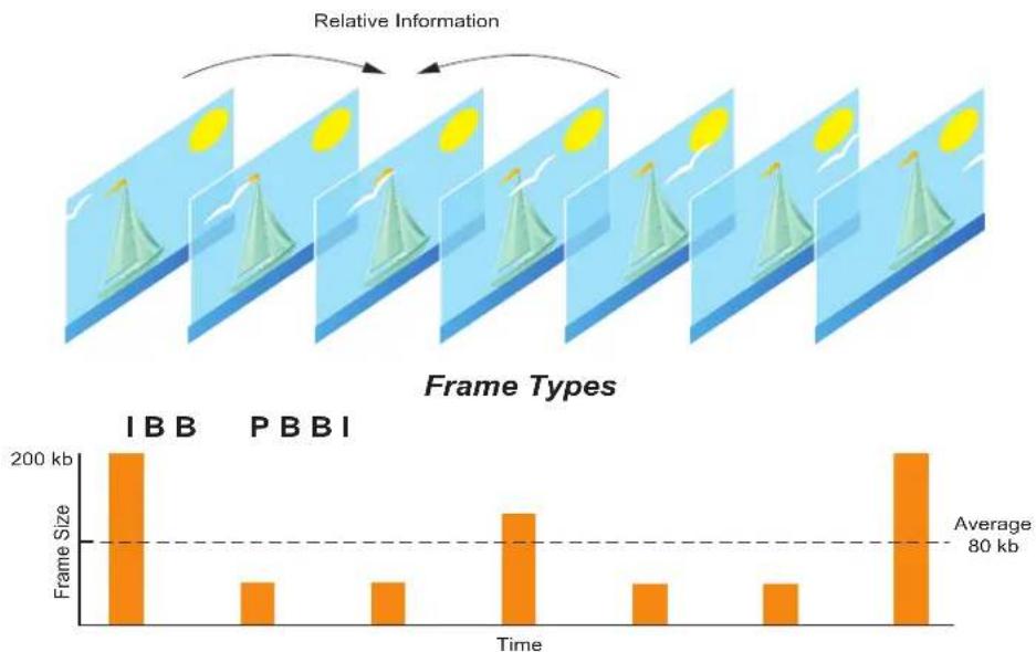
Crestron uses H.264 inter-frame coding, which is an efficient way of transmitting video. During inter-frame coding, several frames of video are broken into a group of pictures (GOP). The GOP is the set of data that the encoder uses to create the compressed stream. The illustration below shows the relationship between a GOP and the three frame types: B-Frame, I-Frame, and P-Frame.
Inter-frame Coding Example
bar
| Frame Type | Time Point | Frame Size (kb) | | :--- | :--- | :--- | | I | 1 | 200 | | B | 2 | 50 | | P | 3 | 50 | | B | 4 | 100 | | I | 5 | 50 | | B | 6 | 50 | | P | 7 | 50 | | I | 8 | 200 | The chart includes an annotation 'Relative Information' and a secondary bar chart below showing the 'Average' frame size at 80 kb.Frame Type Type Definition
| B-Frame | Bi-directional | B-Frame uses information from the previous and next I and P frames to calculate the change in the picture. This frame has the least information and relies on the other information being available. |
| I-Frame | Intra | I-Frame is the full picture and provides everything the decoder needs to create a frame. If a single I-Frame is decoded, the complete picture is viewable.I-Frames are the least compressible. |
| P-Frame | Predicted | P-Frame uses data from the previous and next I-Frame to calculate the change in the picture. P-frames are more compressible than I-Frames. |
Intra-frame Coding (JPEG2000)
Intra-frame coding is a coding method in which only full frames are sent. As in a flip book, each complete image is presented in order to create a moving picture. This coding technique has the advantage of reducing latency, but at a significant cost to bandwidth. JPEG2000 can be used because it has no provisions for frame types other than full frames. The example below shows the relationship between a GOP and an I-Frame type.
Intra-frame Coding Example

The advantages and disadvantages of inter-frame coding versus intra-frame coding are shown in the table below.
| Inter-frame Coding Intra-frame Coding | ||
| Advantages • Very | good picture qualityLow bandwidth | Low latencyMinor distortion if data is missing or corrupted |
| Disadvantages • High | latencyRequires other frames to decodeShows distortion if data is missing or corrupted | Very high bandwidth |
Protocols
Streaming uses transport and streaming protocols to control the transfer of data.
Transport Protocols
User Datagram Protocol (UDP) and Transmission Control Protocol (TCP) are the transport protocols that are used to carry data to and from devices.
- UDP is a simple protocol with less overhead. It is used for one-to-many communications and for real-time transmissions in which the timing of the data is important. UDP does not have a retry function or other mechanisms to correct data errors.
- TCP has guaranteed delivery with mechanisms to retry and handle data errors. It is used mainly for one-to-one communications. TCP is not the best choice for streaming audio and video.
Streaming Protocols
Real-time Control Protocol (RTCP), Real-time Streaming Protocol, and Real-time Transport Protocol are the protocols used in streaming.
- RTCP carries statistics and information about the stream. It is used to ensure quality of service by adjusting the RTP stream so that it can handle changing network conditions.
- RTSP is used in conjunction with RTP and RTCP. This protocol does not stream the data but acts as the means to set up the transport and control the flow. It offers transport control capabilities such as pause and seek for streaming media.
- RTP defines a standardized packet format for delivering audio and video over IP networks. This protocol is used extensively in communication and A/V systems that involve streaming. There are separate RTP streams for audio. RTP is usually not encapsulated.
There is one RTP stream per payload. For example, a session with one video stream and one audio stream has two RTP streams on two separate ports. The packet contains the information required to check for packet drops, out-of-order delivery, timing, and identification of the payload.
Connecting to a Stream
The two main ways to connect to a stream are using either multicast or unicast.
Multicast Sessions
Multicast is the delivery of messages or information to a group of destination computers simultaneously in a single transmission from the source. A multicast transmission sends data only to interested destinations by using special address assignments. The device sends data to a group that is represented by a single multicast address (IPv4 range 224.0.0.0 to 239.255.255.255, IPv6 FF00::/8). Multicast sessions are a one-to-many connection between the server and the clients. The server and the clients connect to the multicast address and the network hardware replicates the packets.
A multicast scenario consists of a single server that broadcasts across the network. Individual clients have the option to tune in or not. The broadcast is handled by the network switches instead of by the device generating the stream. The total bandwidth consumption at the transmitter is the amount used by a single stream. Multicast sessions require specialized network hardware and a more in-depth network configuration requiring a specific router setup.
Multicast Session Example

flowchart
graph TD
    A["SERVER"] --> B["Office 1"]
    A --> C["Office 2"]
    A --> D["Office 3"]
    B --> E["Computer 1"]
    C --> F["Computer 2"]
    D --> G["Computer 3"]
    style A fill:#f9f,stroke:#333
    style B fill:#ccf,stroke:#333
    style C fill:#ccf,stroke:#333
    style D fill:#ccf,stroke:#333
Unicast Sessions
Unicast is the delivery of messages or information to a single network destination identified by a unique address. A unicast transmission sends the same data to all possible destinations.
Unicast sessions are direct connections between the client and the server. This type of session has the advantage of being easier to manage and configure since no special configuration of the network equipment is required. In addition, unicast can be sent through routers without any additional configuration. There are two ways to initiate a unicast connection:
• The device transmitting waits for clients to connect.
• The device transmitting initiates a connection to a server.
Although unicast is the norm for most Internet connections, it does not scale well when many listeners want to view the same program concurrently. The bandwidth consumption is multiplied by the number of listeners. Unicast sessions are well suited for delivery of media on demand but issues can arise when synchronizing live content.
A disadvantage of unicast is that the host must send a packet for each connected client, resulting in duplication and increased bandwidth consumption. For example, if ten clients are connected, the same packet must be sent to each individual client.
Unicast Session Example

flowchart
graph TD
    A["SERVER"] --> B["Client 1"]
    A --> C["Client 2"]
    A --> D["Client 3"]
    B --> E["Computer 1"]
    C --> F["Computer 2"]
    D --> G["Computer 3"]
Crestron's Approach to Streaming
Crestron's approach is to integrate streaming media conversation and distribution onto a digital matrix switcher using a DM® distribution solution. The user can feed any video type to a DM system and stream video. DM creates a seamless transition between high-definition, lossless video and the streaming video. DM with streaming provides the ability to distribute any combination of sources to virtually any device anywhere. A gigabit Ethernet backbone is at the core of all DM switchers.
The illustration below shows how DM can leverage streaming to connect two remote sites to each other. The top system is located in New York, and the bottom system is located in Tokyo. Using Crestron's standard input and output cards, the two laptops are connected to their respective chassis. Using streaming capabilities, the content displayed on the laptop in New York, can be displayed on the laptop in Tokyo as if the laptops were connected by a DM cable.
Streaming to Remote Sites using DM Example

flowchart
graph TD
    A["DMC-HD"] --> B["DM-MDBX8"]
    B --> C["DISPLAY"]
    C --> D["NEW YORK"]
    B --> E["DMC STR"]
    E --> F["WAN/LAN"]
    F --> G["DMC STR"]
    G --> H["DM-MDBX8"]
    H --> I["DISPLAY"]
    I --> J["TOYKO"]
    K["LAPTOP"] --> L["NEW YORK"]
Streaming expands the capabilities of DM by removing all distance limitations and allowing distribution to virtually any device—anywhere in the world. A high-performance H.264 streaming capability enables enterprise-wide distribution of HD content over an IP network.
Streaming is an essential component of any complete DM system, allowing for high-definition signal routing to Crestron touch screens, digital signage displays, remote buildings, and global offices without requiring any new or dedicated wiring. Large-scale streaming to computers and mobile devices can be facilitated through integration with a streaming media server.
Each streaming output supports resolutions up to HD 1080p at bitrates up to 25 Mbps. Built-in scaling enables fast, trouble-free switching between sources of any type or resolution. Audio support includes stereo signals as well as multichannel audio signals down-mixed to stereo using a DM switcher input card with Digital Signal Processing (DSP). High-quality video and audio are maintained using high-performance H.264 video and AAC compression. The encoded video and audio can be output as independent RTP streams or encapsulated in an MPEG-2 Transport Stream (MPEG-TS) container. High-bandwidth Digital Content Protection (HDCP) management ensures that protected content cannot be distributed using streaming.
Each streaming output is fed internally by two separate switcher outputs that allow any two input sources to appear picture-in-picture or side-by-side in a single stream. Instant, single-frame switching between two full screen images is also possible. The audio signals from both input sources can also be mixed, which allows both signals to be heard simultaneously.
DigitalMedia provides many deployment options to address a wide range of streaming applications and accommodate each organization's specific IT requirements. DM with streaming supports both unicast and multicast, with or without RTSP. Streaming connections can be configured to stream directly to one or more specific IP addresses, or to use RTSP to manage the configuration of numerous connections automatically. Any streaming output may be configured to stream using either the DM switcher's LAN port or a dedicated CONTENT LAN port that provides the option to either combine control and content on a single network or isolate them onto separate networks.
All DM streaming cards include a dedicated content port. This Ethernet port can be connected to the content network, completely separating control and content. For smaller installations, the streaming cards can use the DM internal network. This makes for a simple and clean installation.
Crestron manages the HDCP protected content ensuring that it is not transmitted over a streaming device. DM transmitters and receivers can coexist with streaming devices. DM provides ultrahigh bandwidth and HDCP for when streaming limits are reached.
When data rates prohibit Ethernet, there is a place for circuit-switched networks. Circuit-switched networks fill the gap when it is not feasible to run a dedicated video link, but video is still desired. Crestron allows the use of both circuit switches and streaming devices in the same A/V network. The reliability and familiarity of the circuit switch is retained while the benefits and features of Ethernet can be explored.
The new software technologies enable automatic desktop streaming using Wi-Fi ® and Ethernet with fast and seamless connection to any A/V system. This eliminates the need for bulky VGA or DVI cables, panels, vaults, or dongles.
Since the IT infrastructure currently exists throughout the building, small rooms that were previously ignored or underbudgeted can now be accessed. For every room with traditional A/V, dozens of rooms are now within the reach of the IT infrastructure using Wi-Fi.
Ethernet Configuration for Content LAN Port
DMC-STRO cards stream audio and video over an Ethernet network. A stream can be sent using either the CONTENT LAN port of a streaming output card or the LAN port of a DM switcher.
Using Crestron Studio™, SIMPL Windows, or DMTool, set the operational mode of the CONTENT LAN port to any of the following:
- Auto: When in automatic mode (default setting), a streaming output card outputs a stream using the CONTENT LAN port but only if a link is detected. If a link is not detected, the card uses the internal DigitalMedia network via the LAN port of the DM switcher.
- Enable: If the CONTENT LAN port is enabled, the card streams content using the CONTENT LAN port regardless of whether a link is detected or not.
- Disable: If the CONTENT LAN port is disabled, the card streams content using the internal DigitalMedia network regardless of whether a link is detected or not.
NOTE: Regardless of the operational mode and link status of the CONTENT LAN port, an Ethernet connection to the CPU card of the DigitalMedia switcher is necessary for control of the switcher.
The CONTENT LAN port allows a system designer to have separate LAN connections for control and content. A few sample scenarios are shown below:
- Streaming a live show: The control LAN can connect to the products in the booth that do not have Internet access and the content LAN can connect to a network that has Internet access.
- The DigitalMedia switcher sits behind a control subnet and streams content to a device on the corporate LAN.
- The IP address of the streaming output card encoder differs from the IP address of the DigitalMedia switcher. By default, Dynamic Host Configuration Protocol (DHCP) is enabled for the streaming output card encoder.
- Using the internal DigitalMedia network: The encoder is on the same network as the CPU card of the DM switcher and requests an IP address from the same DHCP server.
- Using the CONTENT LAN port: The encoder can be on a different network and request an IP address from the DHCP server on that network.
- Similar to other types of DM switcher output cards, DMC-STRO cards receive a private IP address from the DM switcher in Private Network Mode (PNM); however, DMC-STRO cards also include a dedicated encoder that requires its own IP address. The encoder always requires a public IP address outside of the private DM network.
The DMC-STR supports high-performance H.264 streaming video at resolutions up to HD 1080p and bitrates up to 25 Mbps. The stream is decoded and converted to HDMI ® to allow for switching and distribution using DigitalMedia.
Multichannel AAC audio decoding provides support for surround sound sources up to 7.1. Built-in downmixing allows the multichannel signal to be routed to a surround sound system while simultaneously providing a 2-channel downmix to feed a stereo zone or audio distribution system.
HDMI and stereo analog audio outputs are provided on the DMC-STR card. The HDMI output can be used to pass the decoded input signal through to a local audio processor or video monitor or to feed a second DM switcher for output expansion purposes. The analog audio output, which features programmable volume control, outputs the 2-channel downmix signal to feed a stereo amplifier or multiroom audio distribution system.
The DMC-STR can be configured to receive streaming signals using the DM switcher's LAN port or using a dedicated CONTENT LAN port. This option allows for combined control and content on a single network or isolated control on separate networks.
The DMC-STR can also be used with the DMCI DigitalMedia Card Interface, which allows it to function as a streaming receiver to feed a single display device, A/V receiver, or other equipment.
Refer to the DigitalMedia Resources web page for additional design tools and reference documents.
Crestron Streaming-Related Products
The Crestron products shown in this section can be utilized as part of a streaming solution.
NOTE: For more information on Crestron streaming-related products, refer to www.crestron.com.
DMC-STR
The DMC-STR is an input card for a Crestron DigitalMedia switcher that provides one streaming input. The streaming input receives a single H.264 video stream over an IP network from another DM switcher, an IP camera, a streaming server (CEN-NVS200), or a Capture HD ® system. Streaming inputs expand the capabilities of a DM system, enabling high-definition A/V signal routing from sources anywhere in the world.

DMC-STRO
The DMC-STRO is an output card for a Crestron DigitalMedia switcher that provides streaming output. Using the DMC-STRO, create an H.264 streaming video output from any DM input, including HD video brought into the switcher using an HDMI input card.

CAPTURE-HD
The Capture HD high-definition capture recorder provides a very simple and cost-effective solution for capturing lectures, presentations, medical procedures, seminars, and training sessions in high-definition 1080p. It can also be used to stream live HD video and audio to a computer, mobile device, touch screen, DM system, or third-party streaming media system via H.264. CAPTURE-HD supports both unicast and multicast, with or without RTSP. Streaming connections can be configured to stream directly to one or more specific IP addresses or to use RTSP to manage the configuration of multiple connections automatically.

CEN-NVS200
The CEN-NVS200 is a network video streamer that delivers live streaming video to Crestron touch screens and mobile devices. The CEN-NVS200 provides a powerful solution for delivering video over Ethernet from a camera or other analog video source. Audio is also supported to monitor an audio signal interleaved with the video signal. The CEN-NVS200 supports multiple streams with different formats and quality settings and is ideal for streaming video and audio simultaneously to a variety of Crestron touch screens, computers, and mobile devices.
Video streaming capabilities include high-performance H.264, MPEG-4, and MJPEG compression formats. These formats are compatible with Crestron devices and software as well as computer web browsers. A versatile range of settings allows the optimization of each individual stream for its intended application and the capabilities of the network. Video compression settings include frame rate, resolution, image quality, brightness, contrast, saturation, and sharpness. The CEN-NVS200 supports very high-quality video streaming up to 30 fps at 720x480 (NTSC) or 25 fps at 720x576 (PAL) resolutions.

natural_image
Black electronic device with ports and buttons, no visible text or symbols on bodyCrestron App
View live motion video right from the Crestron App. Video can be displayed in a window within the Crestron App. View what is going on while simultaneously communicating over the intercom and granting access to guests through a secured door or motorized gate. Native support for the MJPEG format allows the display of live video images from IP cameras and servers such as the Crestron CEN-NVS200 Network Video Streamer.

natural_image
Five electronic devices displaying smart home interfaces with control panels and app icons (no readable text or symbols)CEN-SWPOE-16
The CEN-SWPOE-16 offers control system networking and Crestron guaranteed performance and reliability for a complete Ethernet network of touch screens, control processors, servers, and other devices in a single-space rack mount package. All 16 ports are gigabit capable to ensure maximum bandwidth for multimedia and critical control data.

Touch Screens
Crestron touch screens offer an ideal user interface for controlling all of a building's technology. Touch screens are fully customizable with easy-to-use controls and icons for use with live streaming video.
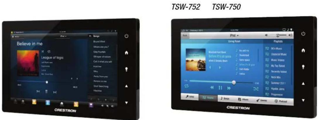
The TSW touch screens contain high-performance streaming video capability, which makes it possible to view security camera feeds and other video sources directly on the touch screen. Native support for H.264 and MJPEG formats allows the TSW-750 to display live streaming video from an IP camera, a streaming server (CEN-NVS200), a DigitalMedia switcher, or a Capture HD system. Video is delivered to the touch screen over Ethernet, which eliminates the need for any extra video wiring.
NOTE: Refer to "Appendix B: Streaming Applications" on page 16 for streaming applications using Crestron products.
Appendix A: RTSP Connection Process
In most cases, RTSP sets up the connection between a client and a server. During this process, details about the stream are exchanged so that the decoder can be properly initialized. The process steps are shown below.
- The client connects to the server from a URL. The client issues the OPTIONS command.
- The server responds with the options it supports (typically, DESCRIBE, SETUP, TEARDOWN, PLAY, and PAUSE).
- The client issues the DESCRIBE command.
- The server responds with the session description, which defines the streams available (audio, video formats, IDs, etc.)
- The client issues the SETUP command for each stream requested. At this point, the client usually requests the ports to which the server should send the data.
- The server responds, confirming the ports to which it sends the data and informing the client from which port the data originates.
- The client issues the PLAY command to start the stream. The client can specify where to start and end the stream, or it can play the whole stream.
- The server responds, confirming the URL and starts playing. The media is now playing and the client is receiving.
- The client issues the TEARDOWN command to stop the stream.
- The connection is closed on the server side.
- The connection is closed on the client side.
Stateful Connections with Layers

flowchart
graph TD
    A["Compressed Video/Audio"] --> B["Data Plane"]
    A --> C["Control Plane"]
    B --> D["RTP Layer"]
    C --> E["RTCP Layer"]
    C --> F["RTSP Layer"]
    D --> G["UDP"]
    E --> H["TCP"]
    F --> I["IPv4. IPv6"]
    G --> J["INTERNET"]
    H --> J
    I --> J
Appendix B: Streaming Applications
Physical Connections—Streaming to Touch Screens Using Unicast via RTSP
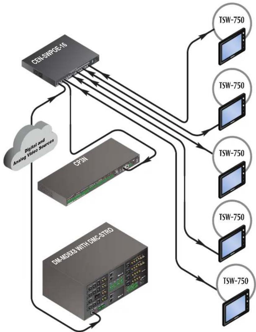
Unicast via RTSP is the most direct method to begin streaming. The connection parameters are exchanged as part of the RTSP negotiation and the data is sent directly to the connecting device. This process places more stress on the encoder since each packet must be duplicated for each receiver. Refer to the documentation that came with the encoder to determine the number of devices that can be connected.
The DMC-STRO has a maximum bandwidth of 25,000 kbps. To calculate the maximum number of devices that can be connected, use the following formula:
$$ \frac {2 5 , 0 0 0 \mathrm{kbps}}{\text { target bandwidth }} = \text { Number of devices supported } $$
For example, if the target bandwidth equals 5,000 kbps, then the calculation is as follows:
$$ \frac {2 5 , 0 0 0 \mathrm{kbps}}{5 , 0 0 0 \mathrm{kbps}} = 5 \text { simultaneous connections } $$
Physical Connections—Streaming to Touch Screens Using Unicast via RTSP

flowchart
graph TD
    A["CEL-SWPDE-16"] -->|Digital and Analog Video Sources| B["CPAN"]
    A -->|Digital and Analog Video Sources| C["DM-MDBX8 WITH DMC-STRO"]
    A -->|Digital and Analog Video Sources| D["TSW-750"]
    A -->|Digital and Analog Video Sources| E["TSW-750"]
    A -->|Digital and Analog Video Sources| F["TSW-750"]
    A -->|Digital and Analog Video Sources| G["TSW-750"]
    A -->|Digital and Analog Video Sources| H["TSW-750"]
    A -->|Digital and Analog Video Sources| I["TSW-750"]
    A -->|Digital and Analog Video Sources| J["TSW-750"]
    A -->|Digital and Analog Video Sources| K["TSW-750"]
    A -->|Digital and Analog Video Sources| L["TSW-750"]
    A -->|Digital and Analog Video Sources| M["TSW-750"]
    A -->|Digital and Analog Video Sources| N["TSW-750"]
    A -->|Digital and Analog Video Sources| O["TSW-750"]
    A -->|Digital and Analog Video Sources| P["TSW-750"]
    A -->|Digital and Analog Video Sources| Q["TSW-750"]
    A -->|Digital and Analog Video Sources| R["TSW-750"]
    A -->|Digital and Analog Video Sources| S["TSW-750"]
    A -->|Digital and Analog Video Sources| T["TSW-750"]
    A -->|Digital and Analog Video Sources| U["TSW-750"]
    A -->|Digital and Analog Video Sources| V["TSW-750"]
    A -->|Digital and Analog Video Sources| W["TSW-750"]
    A -->|Digital and Analog Video Sources| X["TSW-750"]
    A -->|Digital and Analog Video Sources| Y["TSW-750"]
    A -->|Digital and Analog Video Sources| Z["TSW-750"]
    A -->|Digital and Analog Video Sources| AA["TSW-750"]
    A -->|Digital and Analog Video Sources| AB["TSW-750"]
    A -->|Digital and Analog Video Sources| AC["TSW-750"]
    A -->|Digital and Analog Video Sources| AD["TSW-750"]
    A -->|Digital and Analog Video Sources| AE["TSW-750"]
    A -->|Digital and Analog Video Sources| AF["TSW-750"]
    A -->|Digital and Analog Video Sources| AG["TSW-750"]
    A -->|Digital and Analog Video Sources| AH["TSW-750"]
    A -->|Digital and Analog Video Sources| AI["TSW-750"]
    A -->|Digital and Analog Video Sources| AJ["TSW-750"]
    A -->|Digital and Analog Video Sources| AK["TSW-750"]
    A -->|Digital and Analog Video Sources| AL["TSW-750"]
    A -->|Digital and Analog Video Sources| AM["TSW-750"]
    A -->|Digital and Analog Video Sources| AN["TSW-750"]
    A -->|Digital and Analog Video Sources| AO["TSW-750"]
    A -->|Digital and Analog Video Sources| AP["TSW-750"]
    A -->|Digital and Analog Video Sources| AQ["TSW-750"]
    A -->|Digital and Analog Video Sources| AR["TSW-750"]
    A -->|Digital and Analog Video Sources| AS["TSW-750"]
    A -->|Digital and Analog Video Sources| AT["TSW-750"]
    A -->|Digital and Analog Video Sources| AU["TSW-750"]
    A -->|Digital and Analog Video Sources| AV["TSW-750"]
    A -->|Digital and Analog Video Sources| AW["TSW-750"]
    A -->|Digital and Analog Video Sources| AX["TSW-750"]
    A -->|Digital and Analog Video Sources| AY["TSW-750"]
    A -->|Digital and Analog Video Sources| AZ["TSW-750"]
    A -->|Digital and Analog Video Sources| BA["TSW-750"]
    A -->|Digital and Analog Video Sources| BB["TSW-750"]
    A -->|Digital and Analog Video Sources| BC["TSW-750"]
    A -->|Digital and Analog Video Sources| BD["TSW-750"]
    A -->|Digital and Analog Video Sources| BE["TSW-750"]
    A -->|Digital and Analog Video Sources| BF["TSW-750"]
    A -->|Digital and Analog Video Sources| BG["TSW-750"]
    A -->|Digital and Analog Video Sources| BH["TSW-750"]
    A -->|Digital and Analog Video Sources| BI["TSW-750"]
    A -->|Digital and Analog Video Sources| BJ["TSW-750"]
    A -->|Digital and Analog Video Sources| BK["TSW-750"]
    A -->|Digital and Analog Video Sources| BL["TSW-750"]
    A -->|Digital and Analog Video Sources| BM["TSW-750"]
    A -->|Digital and Analog Video Sources| BN["TSW-750"]
    A -->|Digital and Analog Video Sources| BO["TSW-750"]
    A -->|Digital and Analog Video Sources| BP["TSW-750"]
    A -->|Digital and Analog Video Sources| BQ["TSW-750"]
    A -->|Digital and Analog Video Sources| BR["TSW-750"]
    A -->|Digital and Analog Video Sources| BS["TSW-750"]
    A -->|Digital and Analog Video Sources| BT["TSW-750"]
    A -->|Digital and Analog Video Sources| BU["TSW-750"]
    A -->|Digital and Analog Video Sources| BV["TSW-750"]
    A -->|Digital and Analog Video Sources| BW["TSW-750"]
    A -->|Digital and Analog Video Sources| BX["TSW-750"]
    A -->|Digital and Analog Video Sources| BY["TSW-750"]
    A -->|Digital and Analog Video Sources| BZ["TSW-750"]
    A -->|Digital and Analog Video Sources| CA["TSW-750"]
    A -->|Digital and Analog Video Sources| CB["TSW-750"]
    A -->|Digital and Analog Video Sources| CC["TSW-750"]
    A -->|Digital and Analog Video Sources| OD["TSW-750"]
    A -->|Digital and Analog Video Sources| BE["TCW"]<br>Sw/Sw/Sw/Sw/Sw/Sw/Sw/Sw/Sw/Sw/Sw/Sw/Sw/Sw/Sw/Sw/Sw/Sw/Sw/Sw/Sw/Sw/Sw/Sw/Sw/Sw/Sw/Sw/Sw/Sw/Sw/Sw/Sw/Sw/Sw/Sw/Sw/Sw/Sw/Sw/Sw/Sw/Sw/Sw/Sw/Sw/Sw/Sw/Sw/Sw/Sw/Bz/Tsw/Sw/Sw/Sw/Sw/Sw/Sw/Sw/Sw/Sw/Sw/Sw/Sw/Sw/Sw/Sw/Sw/Sw/Sw/Sw/Sw/Sw/Sw/Sw/Sw/Sw/Sw/Sw/Sw/Sw/Sw/Sw/Sw/Sw/Sw/Sw/Sw/Sw/Sw/Sw/Bz/Tsw/Sw/Sw/Sw/Sw/Sw/Sw/Sw/Sw/Swa/Bz/Tsw/Sw/Sw/Sw/Sw/Swa/Bz/Tsw/Sw/Sw/Swa/Bz/Tsw/Sw/Swa/Bz/Tsw/Sw/Swa/Bz/Tsw/Sw/Swa/Bz/Tsw/Sw/Swa/Bz/Tsw/Sw/Swa/Bz/Tsw/Sw/Swa/Bz/Tsw/Sw/Swa/Bz/Tsw/TSW
Logical Connections—Streaming to Touch Screens Using Unicast via RTSP
The illustration below shows the logical connections needed for a DMC-STRO card to stream content to touch screens using unicast via RTSP. The following details are shown:
- The TSW-750 touch screens are configured to connect directly to a DMC-STRO card.
• The connection between each touch screen and the DMC-STRO card is a unicast RTSP connection. - The packets are duplicated for each touch screen.
- Since the touch screens are on the same network, the CONTENT LAN port of the DMC-STRO card is disabled; therefore, the card streams content using the internal DigitalMedia network.
Logical Connections—Streaming to Touch Screens Using Unicast via RTSP

flowchart
graph TD
    A["LAPTOP"] --> B["DMC-HD"]
    B --> C["DM-MDBX8"]
    C --> D["DMC-STRO"]
    D --> E["TSW-750"]
    D --> F["TSW-750"]
    D --> G["TSW-750"]
    D --> H["TSW-750"]
    C --> I["CONTROL SYSTEM CP3"]
    style A fill:#4CAF50,stroke:#333
    style B fill:#E6F3FF,stroke:#333
    style C fill:#90EE90,stroke:#333
    style D fill:#E6F3FF,stroke:#333
    style E fill:#E6F3FF,stroke:#333
    style F fill:#E6F3FF,stroke:#333
    style G fill:#E6F3FF,stroke:#333
    style H fill:#E6F3FF,stroke:#333
    style I fill:#4CAF50,stroke:#333
Physical Connections—Streaming to Content Management Server Using Unicast
The illustration below shows the physical connections needed for a DMC-STRO card to stream content to a content management server using unicast. The streaming output card is configured to connect to an IP address and can traverse firewalls.
Physical Connections—Streaming to Content Management Server Using Unicast

flowchart
graph TD
    A["CAMERA"] --> B["LAPTOP"]
    B --> C["CM-MDG8A-Wi DMC-STRO"]
    C --> D["CP3"]
    D --> E["THIRD-PARTY ROUTER"]
    E --> F["Corporate LAN and Points Beyond"]
    C --> G["CEN-SWPOE-16"]
Logical Connections—Streaming to Content Management Server Using Unicast
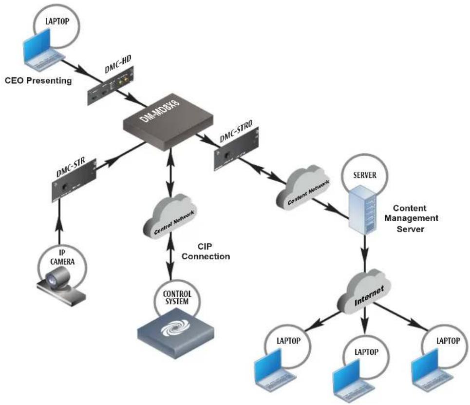
The illustration below shows the logical connections needed for a DMC-STRO card to stream content to a content management server using unicast. The following details are shown:
- The CEO is presenting in both a lecture hall and executive conference center.
• A feed is sent from the laptop to the DM-MD8X8 switcher, which also has a camera connected to it. - Due to the compositing feature of the DMC-STRO, the two sources (camera and laptop) can be combined in a single H.264 stream. The DMC-STRO card is configured to connect to a content management server at a remote location. Only one connection is required between the DMC-STRO card and the content management server.
- The content management server connects to the Internet.
• To view the presentation, users should connect their devices to the content management server.
- The DM-MD8X8 switcher connects to the control LAN.
- The CONTENT LAN port of the DMC-STRO card connects to the corporate LAN.
- The control LAN is isolated from the corporate LAN.
Logical Connections—Streaming to Content Management Server Using Unicast
flowchart
graph TD
    A["LAPTOP"] --> B["CEO Presenting"]
    B --> C["DMC-HD"]
    C --> D["DM-MDBX8"]
    D --> E["DMC-STR"]
    E --> F["IP CAMERA"]
    D --> G["Control Network"]
    G --> H["CIP Connection"]
    H --> I["CONTROL SYSTEM"]
    I --> J["Server"]
    J --> K["Content Management Server"]
    K --> L["Internet"]
    L --> M["LAPTOP"]
    L --> N["LAPTOP"]
    L --> O["LAPTOP"]
    D --> P["DMC-STRO"]
    P --> Q["Content Network"]
    Q --> R["Server"]
    R --> S["Internet"]
Physical Connections—Streaming to Touch Screens Using Multicast via RTSP
Unlike unicast, multicast can stream content to any number of touch screens, but it requires enterprise-grade networking equipment for longer subnet management. The illustration below shows the physical connections needed for a DMC-STRO card to stream content to touch screens using multicast via RTSP.
NOTE: The network hardware and configuration must support multicasting.
NOTE: Unmanaged Ethernet switches treat multicast traffic as broadcast traffic. Multiple multicast streams can exceed the switch fabric's bandwidth.
Physical Connections—Streaming to Touch Screens Using Multicast via RTSP
flowchart
graph TD
    A["CEL-SWPCE-16"] -->|Digital and Analog Video Sources| B["CPON"]
    A -->|Digital and Analog Video Sources| C["DM-MDBX8 WITH DMC-STRO"]
    A -->|Digital and Analog Video Sources| D["TSW-750"]
    A -->|Digital and Analog Video Sources| E["TSW-750"]
    A -->|Digital and Analog Video Sources| F["TSW-750"]
    A -->|Digital and Analog Video Sources| G["TSW-750"]
    A -->|Digital and Analog Video Sources| H["TSW-750"]
    A -->|Digital and Analog Video Sources| I["TSW-750"]
    A -->|Digital and Analog Video Sources| J["TSW-750"]
    A -->|Digital and Analog Video Sources| K["TSW-750"]
    A -->|Digital and Analog Video Sources| L["TSW-750"]
    A -->|Digital and Analog Video Sources| M["TSW-750"]
    A -->|Digital and Analog Video Sources| N["TSW-750"]
    A -->|Digital and Analog Video Sources| O["TSW-750"]
    A -->|Digital and Analog Video Sources| P["TSW-750"]
    A -->|Digital and Analog Video Sources| Q["TSW-750"]
    A -->|Digital and Analog Video Sources| R["TSW-750"]
    A -->|Digital and Analog Video Sources| S["TSW-750"]
    A -->|Digital and Analog Video Sources| T["TSW-750"]
    A -->|Digital and Analog Video Sources| U["TSW-750"]
    A -->|Digital and Analog Video Sources| V["TSW-750"]
    A -->|Digital and Analog Video Sources| W["TSW-750"]
    A -->|Digital and Analog Video Sources| X["TSW-750"]
    A -->|Digital and Analog Video Sources| Y["TSW-750"]
    A -->|Digital and Analog Video Sources| Z["TSW-750"]
    A -->|Digital and Analog Video Sources| AA["TSW-750"]
    A -->|Digital and Analog Video Sources| AB["TSW-750"]
    A -->|Digital and Analog Video Sources| AC["TSW-750"]
    A -->|Digital and Analog Video Sources| AD["TSW-750"]
    A -->|Digital and Analog Video Sources| AE["TSW-750"]
    A -->|Digital and Analog Video Sources| AF["TSW-750"]
    A -->|Digital and Analog Video Sources| AG["TSW-750"]
    A -->|Digital and Analog Video Sources| AH["TSW-750"]
    A -->|Digital and Analog Video Sources| AI["TSW-750"]
    A -->|Digital and Analog Video Sources| AJ["TSW-750"]
    A -->|Digital and Analog Video Sources| AK["TSW-750"]
    A -->|Digital and Analog Video Sources| AL["TSW-750"]
    A -->|Digital and Analog Video Sources| AM["TSW-750"]
    A -->|Digital and Analog Video Sources| AN["TSW-750"]
    A -->|Digital and Analog Video Sources| AO["TSW-750"]
    A -->|Digital and Analog Video Sources| AP["TSW-750"]
    A -->|Digital and Analog Video Sources| AQ["TSW-750"]
    A -->|Digital and Analog Video Sources| AR["TSW-750"]
    A -->|Digital and Analog Video Sources| AS["TSW-750"]
    A -->|Digital and Analog Video Sources| AT["TSW-750"]
    A -->|Digital and Analog Video Sources| AU["TSW-750"]
    A -->|Digital and Analog Video Sources| AV["TSW-750"]
    A -->|Digital and Analog Video Sources| AW["TSW-750"]
    A -->|Digital and Analog Video Sources| AX["TSW-750"]
    A -->|Digital and Analog Video Sources| AY["TSW-750"]
    A -->|Digital and Analog Video Sources| AZ["TSW-750"]
    A -->|Digital and Analog Video Sources| BA["TSW-750"]
    A -->|Digital and Analog Video Sources| BB["TSW-750"]
    A -->|Digital and Analog Video Sources| BC["TSW-750"]
    A -->|Digital and Analog Video Sources| BD["TSW-750"]
    A -->|Digital and Analog Video Sources| BE["TSW-750"]
    A -->|Digital and Analog Video Sources| BF["TSW-750"]
    A -->|Digital and Analog Video Sources| BG["TSW-750"]
    A -->|Digital and Analog Video Sources| BH["TSW-750"]
    A -->|Digital and Analog Video Sources| BI["TSW-750"]
    A -->|Digital and Analog Video Sources| BJ["TSW-750"]
    A -->|Digital and Analog Video Sources| BK["TSW-750"]
    A -->|Digital and Analog Video Sources| BL["TSW-750"]
    A -->|Digital and Analog Video Sources| BM["TSW-750"]
    A -->|Digital and Analog Video Sources| BN["TSW-750"]
    A -->|Digital and Analog Video Sources| BO["TSW-750"]
    A -->|Digital and Analog Video Sources| BP["TSW-750"]
    A -->|Digital and Analog Video Sources| BQ["TSW-750"]
    A -->|Digital and Analog Video Sources| BR["TSW-750"]
    A -->|Digital and Analog Video Sources| BS["TSW-750"]
    A -->|Digital and Analog Video Sources| BT["TSW-750"]
    A -->|Digital and Analog Video Sources| BU["TSW-750"]
    A -->|Digital and Analog Video Sources| BV["TSW-750"]
    A -->|Digital and Analog Video Sources| BW["TSW-750"]
    A -->|Digital and Analog Video Sources| BX["TSW-750"]
    A -->|Digital and Analog Video Sources| BY["TSW-750"]
    A -->|Digital and Analog Video Sources| BZ["TSW-750"]
    A -->|Digital and Analog Video Sources| CA["TSW-750"]
    A -->|Digital and Analog Video Sources| CB["TSW-750"]
    A -->|Digital and Analog Video Sources| CC["TSW-750"]
    A -->|Digital and Analog Video Sources| OD["TSW-750"]
    A -->|Digital and Analog Video Sources| BE["TCN"]<sup>3M</sup>
    B --> C
    C --> D
    D --> E
    E --> F
    F --> G
    G --> H
    H --> I
    I --> J
    J --> K
    K --> L
    L --> M
    M --> N
    N --> O
    O --> P
    P --> Q
    Q --> R
    R --> S
    S --> T
    T --> U
    U --> V
    V --> W
    W --> X
    X --> Y
    Y --> Z
    Z --> AA
    AA --> AB
    AB --> AC
    AC --> AD
    AD --> AE
    AE --> AF
    AF --> AG
    AG --> AH
    AH --> AI
    AI --> AJ
    AJ --> AK
    AK --> AL
    AL --> AM
    AM --> AN
    AN --> AO
    AO --> AP
    AP --> AQ
    AQ --> AR
    AR --> AS
    AS --> AT
    AT --> AU
    AU --> AV
    AV --> AW
    AW --> AX
    AX --> AY
    AY --> AZ
    AZ --> BA
    BA --> BB
    BB --> BC
    BC --> DA
    DA --> AE
Logical Connections—Streaming to Touch Screens Using Multicast via RTSP
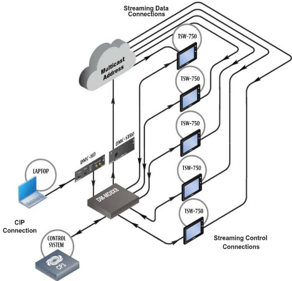
The illustration below shows the logical connections needed for a DMC-STRO card to stream content to touch screens using multicast via RTSP. The following details are shown:
• The TSW-750 touch screens are configured to connect directly to a DMC-STRO card.
- The DMC-STRO card then sends the stream parameters to the touch screens including the multicast address to which the touch screens are to connect. The actual data for the stream comes from the multicast address.
- The DMC-STRO card sends a single stream to the multicast address and the network hardware replicates the address for the devices that are subscribed.
NOTE: The DMC-STRO card begins transmitting only after the first device connects.
NOTE: When using multicast, the CONTENT LAN port must be used. This limitation will be removed in a future firmware update.
Logical Connections—Streaming to Touch Screens Using Multicast via RTSP
flowchart
graph TD
    A["LAPTOP"] --> B["DMC-HD"]
    B --> C["DM-MD8X8"]
    C --> D["DMC-STRO"]
    D --> E["TSW-750"]
    E --> F["Streaming Data Connections"]
    F --> G["TSW-750"]
    G --> H["DSW-750"]
    H --> I["TSW-750"]
    I --> J["DSW-750"]
    J --> K["TSW-750"]
    K --> L["DSW-750"]
    L --> M["TSW-750"]
    M --> N["DSW-750"]
    N --> O["TSW-750"]
    O --> P["DSW-750"]
    P --> Q["TSW-750"]
    Q --> R["TSW-750"]
    R --> S["TSW-750"]
    S --> T["TSW-750"]
    T --> U["TSW-750"]
    U --> V["TSW-750"]
    V --> W["TSW-750"]
    W --> X["TSW-750"]
    X --> Y["TSW-750"]
    Y --> Z["TSW-750"]
    Z --> AA["TSW-750"]
    AA --> AB["TSW-750"]
    AB --> AC["TSW-750"]
    AC --> AD["TSW-750"]
    AD --> AE["TSW-750"]
    AE --> AF["TSW-750"]
    AF --> AG["TSW-750"]
    AG --> AH["TSW-750"]
    AH --> AI["TSW-750"]
    AI --> AJ["TSW-750"]
    AJ --> AK["TSW-750"]
    AK --> AL["TSW-750"]
    AL --> AM["TSW-750"]
    AM --> AN["TSW-750"]
    AN --> AO["TSW-750"]
    AO --> AP["TSW-750"]
    AP --> AQ["TSW-750"]
    AQ --> AR["TSW-750"]
    AR --> AS["TSW-750"]
    AS --> AT["TSW-750"]
    AT --> AU["TSW-750"]
    AU --> AV["TSW-750"]
    AV --> AW["TSW-750"]
    AW --> AX["TSW-750"]
    AX --> AY["TSW-750"]
    AY --> AZ["TSW-750"]
    AZ --> BA["TSW-750"]
    BA --> BB["TSW-750"]
    BB --> BC["TSW-750"]
    BC --> BD["TSW-750"]
    BD --> BE["TSW-750"]
    BE --> BF["TSW-750"]
    BF --> BG["TSW-750"]
    BG --> BH["TSW-750"]
    BH --> BI["TSW-750"]
    BI --> BJ["TSW-750"]
    BJ --> BK["TSW-750"]
    BK --> BL["TSW-750"]
    BL --> BM["TSW-750"]
    BM --> BN["TSW-750"]
    BN --> BO["TSW-750"]
    BO --> BP["TSW-750"]
    BP --> BQ["TSW-750"]
    BQ --> BR["TSW-750"]
    BR --> BS["TSW-750"]
    BS --> BT["TSW-750"]
    BT --> BU["TSW-750"]
    BU --> BV["TSW-750"]
    BV --> BW["TSW-750"]
Physical Connections—Streaming to Digital Signs Using Multicast via UDP
The illustration below shows the physical connections needed for a DMC-STRO card to stream content to digital signage monitors using multicast via UDP.
NOTE: The network hardware and configuration must support multicasting.
Physical Connections—Streaming to Digital Signs Using Multicast via UDP

flowchart
graph TD
    A["CEIN-SWPCE-16"] --> B["CP3"]
    A --> C["DM-MD8X8 WITH DMC-STRO"]
    B --> D["Digital Signage"]
    C --> E["Digital Signage"]
    D --> F["Digital Signage"]
    E --> G["Digital Signage"]
    F --> H["Digital Signage"]
    G --> I["Digital Signage"]
    H --> J["Digital Signage"]
    I --> K["Digital Signage"]
Logical Connections—Streaming to Displays Using Multicast via UDP
The illustration below shows the logical connections needed for a DMC-STRO card to stream content to a display using multicast via UDP. The following details are shown:
- All displays are configured to connect to a multicast address.
- RTSP is not used and no configuration parameters are exchanged. The receiving devices either derive stream parameters or recognize the stream parameters a priori. Refer to the receiving device's documentation for details.
- The DMC-STRO card always transmits the stream regardless of whether there are listeners. As a result, devices do not need to negotiate with the DMC-STRO card—the devices can simply reconnect to the stream.
- If the connection between the DMC-STRO card and the multicast address is interrupted, the stream can resume without intervention when the connection is restored.
Logical Connections—Streaming to Displays Using Multicast via UDP

flowchart
graph TD
    A["Control LAN"] --> B["CIP Connection"]
    B --> C["LAPTOP"]
    C --> D["DMC-RD"]
    D --> E["DMC-STRI"]
    E --> F["DMC-STR"]
    F --> G["Multicast Address"]
    G --> H["Display"]
    G --> I["Display"]
    G --> J["Display"]
    G --> K["Display"]
    G --> L["Display"]
    G --> M["Display"]
    G --> N["Display"]
    G --> O["Display"]
    G --> P["Display"]
    G --> Q["Display"]
    G --> R["Display"]
    G --> S["Display"]
    G --> T["Display"]
    G --> U["Display"]
    G --> V["Display"]
    G --> W["Display"]
    G --> X["Display"]
    G --> Y["Display"]
    G --> Z["Display"]
    G --> AA["Display"]
    G --> AB["Display"]
    G --> AC["Display"]
    G --> AD["Display"]
    G --> AE["Display"]
    G --> AF["Display"]
    G --> AG["Display"]
    G --> AH["Display"]
    G --> AI["Display"]
    G --> AJ["Display"]
    G --> AK["Display"]
    G --> AL["Display"]
    G --> AM["Display"]
    G --> AN["Display"]
    G --> AO["Display"]
    G --> AP["Display"]
    G --> AQ["Display"]
    G --> AR["Display"]
    G --> AS["Display"]
    G --> AT["Display"]
    G --> AU["Display"]
    G --> AV["Display"]
    G --> AW["Display"]
    G --> AX["Display"]
    G --> AY["Display"]
    G --> AZ["Display"]
    G --> BA["Display"]
    G --> BB["Display"]
    G --> BC["Display"]
    G --> BD["Display"]
    G --> BE["Display"]
    G --> BF["Display"]
    G --> BG["Display"]
    G --> BH["Display"]
    G --> BI["Display"]
    G --> BJ["Display"]
    G --> BK["Display"]
    G --> BL["Display"]
    G --> BM["Display"]
    G --> BN["Display"]
    G --> BO["Display"]
    G --> BP["Display"]
    G --> BQ["Display"]
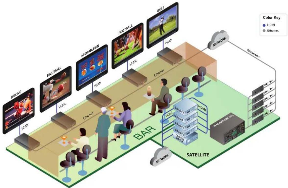
Content Distribution Streaming
The illustration below shows how a restaurant can utilize a streaming content distribution system.
Content Distribution Streaming Example
flowchart
graph TD
    subgraph Satellite
        A["Satellite"] --> B["Network"]
        B --> C["Internet Network"]
        C --> D["Information"]
        D --> E["FOXO"]
        E --> F["GOLF"]
        A --> G["Satellite"]
        G --> H["Network"]
        H --> I["Internet Network"]
        I --> J["Information"]
        J --> K["FOXO"]
        K --> L["GOLF"]
    end

    subgraph BAR
        M["BOXING"] --> N["HDMI"]
        O["BASEBALL"] --> P["HDMI"]
        Q["INFORMATION"] --> R["HDMI"]
        S["FOOTBALL"] --> T["HDMI"]
        U["GOLF"] --> V["HDMI"]
        W["Ethernet"] --> X["Ethernet"]
    end

    style Satellite fill:#f9f9f9,stroke:#333
    style BAR fill:#e6f7ff,stroke:#333
    style Internet Network fill:#e6f7ff,stroke:#333
    style Network fill:#e6f7ff,stroke:#333
    style Internet Network node fill:#e6f7ff,stroke:#333
    style Internet Network edge fill:#e6f7ff,stroke:#333
    style Internet Network node node fill:#e6f7ff,stroke:#333
    style Internet Network edge fill:#e6f7ff,stroke:#333
    style Internet Network node fill:#e6f7ff,stroke:#333
    style Internet Network node node fill:#e6f7ff,stroke:#333
    style Internet Network node node fill:#e6f7ff,stroke:#333
    style Internet Network node node fill:#e6f7ff,stroke:#333
    style Internet Network node node fill:#e6f7ff,stroke:#333
    style Internet Network node node fill:#e6f7ff,stroke:#333
    style Internet Network edge fill:#e6f7ff,stroke:#333
    style Internet Network node fill:#e6f7ff,stroke:#333
    style Internet Network node node fill:#e6f7ff,stroke:#333
    style Internet Network node node fill:fill
    style Internet Network node node fill:fill
    style Internet Network node node fill:fill
    style Internet Network node node fill:fill
    style Internet Network node node fill:fill
    style Internet Network node node fill:fill
    style Internet Network node node fill:fill
    style Internet Network node node fill:fill
    style Internet Network node node fill:fill
    style Internet Network node node fill:fill
    style Internet Network node node fill:empty
Glossary
Advanced Audio Coding (AAC): A standardized, lossy compression and encoding scheme for digital audio. AAC generally achieves better sound quality than MP3 at similar bitrates.
Advanced Video Coding (AVC): A video compression format used for the recording, compression, and distribution of video content.
Bitrate: A target output stream size that is averaged over a period of time.
Dongle: A small piece of hardware that attaches to a computer, TV, or other electronic device. When the dongle is attached, it enables additional functions such as copy protection, audio, video, games, data, or other services.
H.264: A video compression format used for the recording, compression, and distribution of video content.
JPEG2000: An image compression and coding system.
Latency: The time that the encoder and decoder takes to process the video frame.
Lossy: A data encoding method that compresses data by discarding (losing) some of it. Lossy compression is typically associated with image files, such as JPEGs, but can also be used for audio files, like MP3s or AAC files. The lossyness of an image file may show up as jagged edges or pixelated areas. In audio files, the lossyness may produce a watery sound or reduce the dynamic range of the audio.
MP2TS/MPEG-2-TS: An MPEG transport stream is a standard format for transmission and storage of audio, video, and Program and System Information Protocol (PSIP) data. It is used in broadcast systems such as DVB, ATSC, and IPTV.
Quality: A factor that affects how the encoder creates the actual frame. This factor tends to vary by encoder or decoder implementation. A high-quality factor results in an improved image but can affect latency and bandwidth.
Wi-Fi: A technology that allows an electronic device to exchange data or connect to the Internet wirelessly using radio waves.
Crestron World Headquarters
15 Volvo Drive
Rockleigh, NJ 07647
Tel: 1-888.CRESTRON
Fax: 201.767.7676
crestron.com
Refer to the listing of Crestron worldwide offices on the Crestron website
www.crestron.com/offices for assistance within a particular geographic region.

CRESTRON®
Printed in USA Doc. 7610B 6/2015


- Streaming
- Design Guide
- Contents
- Introduction
- Technology behind Streaming
- Crestron's Approach to Streaming
- Ethernet Configuration for Content LAN Port
- Crestron Streaming-Related Products
- Appendix A: RTSP Connection Process
- Appendix B: Streaming Applications
- Glossary
- Purpose of this Design Guide
- What Is Streaming?
- Parameters
- Coding Types
- Intra-frame Coding (JPEG2000)
- Protocols
- Transport Protocols
- Streaming Protocols
- Connecting to a Stream
- Multicast Sessions
- Unicast Sessions
- DMC-STR
- DMC-STRO
- CAPTURE-HD
- CEN-NVS200
- Crestron App
- CEN-SWPOE-16
- Touch Screens
- Physical Connections—Streaming to Touch Screens Using Unicast via RTSP
- Logical Connections—Streaming to Touch Screens Using Unicast via RTSP
- Physical Connections—Streaming to Content Management Server Using Unicast
- Logical Connections—Streaming to Content Management Server Using Unicast
- Physical Connections—Streaming to Touch Screens Using Multicast via RTSP
- Logical Connections—Streaming to Touch Screens Using Multicast via RTSP
- Physical Connections—Streaming to Digital Signs Using Multicast via UDP
- Logical Connections—Streaming to Displays Using Multicast via UDP
- Content Distribution Streaming
Brand : Crestron
Model : CEN-NVS200-PWE
Category : AV Extender