
FI-502 CH Wind Angle - Navigation instrument FURUNO - Free user manual and instructions
Find the device manual for free FI-502 CH Wind Angle FURUNO in PDF.


| Product Type | Wind Angle Indicator |
| Brand | Furuno |
| Model | FI-502 CH Wind Angle |
| Display Type | Analog or Digital (Dial/Needle) |
| Display Size | 4 inches (100 mm) diameter |
| Power Supply | 12-24 V DC, 0.2 A |
| Dimensions | 120 mm x 120 mm x 80 mm (4.72" x 4.72" x 3.15") |
| Weight | 0.6 kg (1.32 lbs) |
| Waterproof Rating | IPX6 (protected against powerful water jets) |
| Operating Temperature | -15°C to +55°C (5°F to 131°F) |
| Mounting | Flush or bracket mount |
| Connection Type | Screw terminals or plug-in connector |
| Backlight | Yes, adjustable brightness |
| Alarm Function | Wind angle deviation alarm (adjustable) |
| Input Signal | Wind vane sensor (0-360° or 0-540°) |
| Measuring Range | 0° to 360° (relative wind angle) |
| Accuracy | ±2° |
| Output | NMEA 0183 (optional) |
| Warranty | 2 years (parts and labor) |
| Maintenance | Clean with soft cloth; avoid solvents |
| Certifications | CE, FCC, NMEA compatible |
Frequently Asked Questions - FI-502 CH Wind Angle FURUNO
User questions about FI-502 CH Wind Angle FURUNO
0 question about this device. Answer the ones you know or ask your own.
Ask a new question about this device
Download the instructions for your Navigation instrument in PDF format for free! Find your manual FI-502 CH Wind Angle - FURUNO and take your electronic device back in hand. On this page are published all the documents necessary for the use of your device. FI-502 CH Wind Angle by FURUNO.
USER MANUAL FI-502 CH Wind Angle FURUNO
The paper used in this manual is elemental chlorine free.
All rights reserved.
Printed in Japan
Pub. No. OME-72660-A1
(DAMI) FI-501/502/505/506
• FURUNO Authorized Distributor/Dealer
A : OCT .2007
A1 : OCT . 17, 2007

* 0 0 0 1 6 6 9 8 2 1 0 *
- The descriptions in this manual are intended for readers with a solid knowledge of English.
- No part of this manual may be copied or reproduced without written permission.
- If this manual is lost or worn, contact your dealer about replacement.
- The contents of this manual and equipment specifications are subject to change without notice.
- The example screens (or illustrations) shown in this manual may not match the screens you see on your display. The screen you see depends on your system configuration and equipment settings.
- Store this manual in a convenient place for future reference.
- FURUNO will assume no responsibility for the damage caused by improper use or modification of the equipment (including software) by an unauthorized agent or a third party.
- When it is time to discard this product it must be done according to local regulations for disposal of industrial waste. For disposal in the USA, refer to the Electronics Industries Alliance (http://www.eiae.org/).

SAFETY INSTRUCTIONS
The operator of this equipment must read these safety instructions before attempting to operate the equipment.

WARNING
Indicates a potentially hazardous situation which, if not avoided, could result in death or serious injury.

CAUTION
Indicates a potentially hazardous situation which, if not avoided, may result in minor or moderate injury.

Warning, Caution

Prohibitive Action

Mandatory Action
Safety instructions for the operator

WARNING

Do not open the equipment.
Only qualified personnel should work inside the equipment.

Do not disassemble or modify the equipment.
Fire or electrical shock can result if the equipment is modified.

Do not operate the equipment with wet hands.
Electrical shock can result.

Make sure no rain or water splash leaks into the equipment.
Fire or electrical shock can result if water leaks into the equipment.

Immediately turn off the power at the switchboard if water leaks into the equipment.
Continued use of the equipment can cause fire or electrical shock.
Safety instructions for the installer

WARNING

Turn off the power at the switchboard before beginning the installation.
Turn off the power to prevent electrical shock.

Make sure the installation site is not subject to water spray.
Fire or electrical shock can result if water leaks into the equipment.

CAUTION

Observe the following compass safe distances to prevent interference to the instruments:
| Standard compass | Steering compass | |
| FI-50 series Instruments | 0.35 m | 0.30 m |
Warning Label
A warning label is attached to the equipment. Do not remove the label. If the label is missing or damaged, contact a FURUNO agent or dealer about replacement.

1.1 Operating Controls .... 1
1.2 Turning the Power On/Off 2
1.3 Adjusting Brilliance and Contrast 2
1.4 Display Layout....3
1.5 Selecting a Display....4
1.6 Selecting Apparent or True Wind Angle, Wind Speed 5
1.7 Displaying Velocity Made Good (VMG) Information 6
1.8 Displaying Tack Angle....6
1.9 Alarms 7
2. FI-505 COURSE PILOT 9
2.1 Operating Controls 9
2.2 Turning the Power On/Off 10
2.3 Adjusting Brilliance and Contrast 10
2.4 Selecting a Display....11
2.5 Unlocked and Locked Heading Modes....12
2.6 Resetting Average Heading Indication 12
3. FI-506 RUDDER....13
3.1 Operating Controls 13
3.2 Turning the Power On/Off 14
3.3 Adjusting Display Brilliance 14
3.4 Calibrating Rudder Angle 14
4. MAINTENANCE,TROUBLESHOOTING 15
4.1 Preventive Maintenance....15
4.2 Troubleshooting....16
5. INSTALLATION....17
5.1 Equipment Lists....17
5.2 Mounting....19
5.3 Wiring 23
5.4 Setting Up....29
SPECIFICATIONS SP-1
PACKING LIST A-1
OUTLINE DRAWINGS......D-1
INTERCONNECTION DIAGRAM S-1
A Word to the Owner of the FI-501, FI-502, FI-505, FI-506
Congratulations on your choice of the FURUNO FI-501 Wind Angle, FI-502 Close Hauled Wind Angle, FI-505 Course Pilot and the FI-506 Rudder, members of the FI-50 series of marine instruments. We are confident you will see why the FURUNO name has become synonymous with quality and reliability.
For over 50 years FURUNO Electric Company has enjoyed an enviable reputation for quality marine electronics equipment. This dedication to excellence is furthered by our extensive global network of agents and dealers.
This equipment is designed and constructed to meet the rigorous demands of the marine environment. However, no machine can perform its intended function unless operated and maintained properly. Please carefully read and follow the recommended procedures for operation and maintenance.
Thank you for considering and purchasing FURUNO equipment.
Features
The FI-50 series provide various analog and digital navigation and environmental data, with digital data displayed on a high quality, backlit LCD. The sturdy weather-proof case is built to stand up to even the harshest of environments.
FI-501, FI-502
The FI-501 Wind Angle and FI-502 Close Hauled Wind Angle provide precise analog wind angle together with digital speed indication. Wind angle is available in True or Apparent.
The main features of the FI-501 and FI-502 are
- True and apparent wind angle and speed
• Maximum wind speed - Velocity made good
- Tack angle
- Alarms for wind speed and wind angle
- Boat speed
- Boat speed, heading
FI-505
The FI-505 Course Pilot displays heading and course information, and its main features are
• Heading and average heading
- Locked heading
- Course made good
- Adjustments for
- Heading response
- Pointer response
- Course made good response
- Pointer alignment
FI-506
The FI-506 Rudder displays rudder angle, and its main features are
- Analog rudder indication
- Alignment with keypads
Standalone configuration

flowchart
graph TD
    A["FI-5001 WIND TRANSDUCER"] --> B["TERMINAL BOX (where necessary)"]
    B --> C["FU501"]
    B --> D["FU502"]
    C --> E["OR"]
    D --> E
    E --> F["12 VDC"]
    style A fill:#f9f,stroke:#333
    style B fill:#ccf,stroke:#333
    style C fill:#cfc,stroke:#333
    style D fill:#fcc,stroke:#333
FI-501/FI-502

NOTICE: Turn on the terminal resistor in the instrument when connecting an NMEA 2000 sensor. For the procedure, see installation chapter.
NMEA 2000 network

flowchart
graph TD
    A["FI-5001 WIND TRANSDUCER"] --> B["TERMINAL BOX (where necessary)"]
    B --> C["FI-501 Wind Angle/FI-502 Close Hauled Wind Angle"]
    C --> D["FI-503 DIGITAL"]
    C --> E["FI-504 MULTI"]
    C --> F["FI-505 COURSE PILOT"]
    C --> G["FI-506 RUDDER"]
    D --> H["NMEA 2000 SENSOR*"]
    E --> I["NMEA 2000 SENSOR*"]
    F --> J["NMEA 2000 SENSOR*"]
    G --> K["NMEA 2000 SENSOR*"]
    H --> L["JUNCTION BOX FI-5002"]
    I --> L
    J --> L
    K --> L
    L --> M["* NMEA 2000 SENSORS\n- Boat speed\n- Depth\n- Heading\n- Navigation\n- Environment\n- Autopilot\n- Engine"]
    M --> N["12 VDC (not necessary if powered by NMEA 2000 network)"]
    style A fill:#f9f,stroke:#333
    style B fill:#ccf,stroke:#333
    style C fill:#cfc,stroke:#333
    style D fill:#fcc,stroke:#333
    style E fill:#fcc,stroke:#333
    style F fill:#fcc,stroke:#333
    style G fill:#fcc,stroke:#333
    style H fill:#ffc,stroke:#333
    style I fill:#ffc,stroke:#333
    style J fill:#ffc,stroke:#333
    style K fill:#ffc,stroke:#333
    style L fill:#fff,stroke:#333
    style M fill:#fff,stroke:#333
    style N fill:#fff,stroke:#333
NOTICE: Turn on the terminal resistor in the terminator of the NMEA 2000 network.
This page is intentionally left blank.
1. FI-501 WIND ANGLE
FI-502 CLOSE HAULED WIND ANGLE
The FI-501 Wind Angle and FI-502 Close Hauled Wind Angle instruments provide precise analog wind angle together with digital speed indication, in true or apparent direction. Wind speed is displayed in knots, meters/second or as a Beaufort scale number.
In addition to wind direction and speed indications these instruments provide:
• Velocity made good (VMG).
- Alarms for minimum and maximum true wind speeds, and high and low apparent wind angles.
1.1 Operating Controls

1.2 Turning the Power On/Off
To power the instrument, press the MODE key. All LCD segments go on and off and then the last-used display appears.
To power off the instrument, press the MODE and APP/TRUE keys together. The timer appears and counts down from three seconds to one second, and then the power goes off.

flowchart
graph LR
    A["Press MODE and APP/TRUE keys together"] --> B["3"]
    B --> C["2"]
    C --> D["1"]
    D --> E["POWER OFF"]
Power OFF sequence
1.3 Adjusting Brilliance and Contrast
- Press the MODE and APP/TRUE keys together. The display for adjustment of brilliance appears, with current brilliance setting flashing.

- Within seven seconds of completing step 1, press the VMG key to lower the brilliance, or the TACK/CLEAR key to raise it.
- Press the MODE and APP/TRUE keys together. The display for adjustment of contrast appears, with current contrast setting flashing.

- Within seven seconds of completing step 3, press the VMG key to lower the contrast, or the TACK/CLEAR key to raise it.
- Press the MODE and APP/TRUE keys together to save the settings and restore normal operation.
The brilliance and contrast will be the same on all units which are synchronized. (For how to synchronize units, see page 32.)
1.4 Display Layout
The FI-501 Wind Angle and FI-502 Close Hauled Wind Angle instruments provide analog dial and digital wind information. The display shows that information in true or apparent, depending on mode selected.
The pointer shows the true or apparent wind direction. The apparent wind scale range for the FI-501 is 360^ ( 0^-179^ starboard, 180^-359^ port) and the FI-502 gives an indication of -60^ to +60^ , about the port and starboard of your boat.


Displays
1.5 Selecting a Display
Press the MODE key to select a display. Each press of the key changes the display in the sequence shown below.

flowchart
graph TD
    A["F12"] --> B["Wind speed 12.5 kt APP"]
    B --> C["MAX 13.5 kt TRUE"]
    C --> D["MAX 20.0 kt TRUE"]
    D --> E["5.0 LO kt TRUE"]
    E --> F["300° APP Wind angle"]
    F --> G["High apparent wind angle alarm"]
    G --> H["50° HI APP Low apparent wind angle alarm"]
    H --> I["200° LO APP Low apparent wind angle alarm"]
    I --> J["Beaufort wind speed"]
    J --> A
    style A fill:#f9f,stroke:#333
    style B fill:#ccf,stroke:#333
    style C fill:#cfc,stroke:#333
    style D fill:#fcc,stroke:#333
    style E fill:#cff,stroke:#333
    style F fill:#ffc,stroke:#333
    style G fill:#cfc,stroke:#333
    style H fill:#fcc,stroke:#333
    style I fill:#cfc,stroke:#333
    style J fill:#fcc,stroke:#333
| Display Function Display Function | |||
 | Wind speed. Kt or m/s; true or apparent wind. |  , , | Wind angle. Kt or m/s; true or apparent wind. |
 | Maximum wind speed. Kt or m/s, true or apparent wind. Resettable with the TACK/CLEAR key. |  | Set maximum true wind angle alarm.* |
 | Set maximum true wind speed alarm.* |  | Set low true wind angle alarm.* |
 | Set low true wind speed alarm.* |  | Beaufort wind speed. Beau-fort speeds up to 12 are shown. See the table at the top of the next page for Beaufort no. and wind speed. |
* Audio and visual alarms released when wind speed (or wind angle) is higher (or lower) than threshold value.
| Beaufort no. | Wind speed | Beaufort no. | Wind speed | ||
| ktm/sktrn/s | |||||
| 000-0.2728 | -3314.4-17.4 | ||||
| 11-30.5-2.0 | 834-4017.5-21.0 | ||||
| 24-62.1-3.5 | 941-4721.1-24.6 | ||||
| 37-103.6-5. | 61048-55 | 24.7-28.8 | |||
| 411-16 | 5.7-8.611 | 56-63 | 28.9-32.6 | ||
| 517-218.7- | 11.2 | 1264 | 32.7-32.9 | ||
| 622-2711.3 | -14.3 | ||||
1.6 Selecting Apparent or True Wind Angle, Wind Speed
You can show wind angle and wind speed in apparent or true wind. The apparent wind is the actual flow of air acting upon a sail, or the wind as it appears to the sailor. True wind is the wind seen by a stationary observer in velocity and direction.
With a wind angle or wind speed indication displayed, press the APP/TRUE key to change the wind angle or wind speed to apparent and true alternately. A beep sounds after the change is completed. (Wind angle and wind speed displays are mutually changed.) True wind requires boat speed input. If there is no speed input three dashes appear.

flowchart
graph TD
    A["5.0 kt APP"] --> B["APP TRUE"]
    B --> C["9.6 kt TRUE"]
    C --> A
Apparent and true wind speeds

flowchart
graph TD
    A["135° APP"] --> B["APP TRUE"]
    B --> C["157° TRUE"]
    C --> A
Apparent and true wind angles
1.7 Displaying Velocity Made Good (VMG) Information
VMG is the actual vessel speed after adjusting for such factors as current and wind.
Use the VMG key to display and erase VMG information and current display alternately. (The VMG information cannot be shown when an alarm display is currently shown.). The VMG display requires boat speed information. If no boat speed is available three dashes is shown.

1.8 Displaying Tack Angle
Use the TACK/CLEAR key to display tack angle on the digital display. This function requires speed and heading information. If they are not available, the digital display shows three dashes.

1.9 Alarms
There are four conditions which trigger audio and visual alarms: Maximum true wind speed, Low true wind speed, High apparent wind angle, and Low apparent wind angle.
- Press the MODE key to select desired alarm page, referring to the illustration below.

Max. true wind speed alarm

Low true wind
speed alarm

High apparent
wind angle alarm

Low apparent
wind angle alarm
| Alarm Alarm | released when; Setting range | ||
| Max. true wind speed alarm | wind speed exceeds this threshold. | 0.1-999 kts | |
| Low true wind speed alarm | wind speed is lower than this threshold. | 0-998 kts | |
| High apparent wind angle alarm | wind angle exceeds this threshold. | 0^ - 179^ (Starboard) | Angle side (“S” or “P”) not indicated on FI-501. |
| Low apparent wind angle alarm | wind angle is lower than this threshold. | 180^ - 359^ (Port) | |
- If the selected alarm page shows "OFF," press and hold down the TACK/CLEAR key until an alarm setting appears.
- Press the VMG and TACK/CLEAR keys together to enable adjustment. The alarm setting starts flashing.
- Press the VMG key to lower the setting; the TACK/CLEAR key to raise it.
Note: A low alarm cannot be set higher than its affiliated high (max.) alarm.
- Press the VMG and TACK/CLEAR keys together to confirm setting and restore normal operation.
When an alarm is violated:
- The display shows current wind speed and angle.
- The buzzer sounds and the alarm icon flashes.
You can silence the buzzer with the TACK/CLEAR key. The alarm icon continues flashing until the offending alarm is disabled.
While the icon is flashing you can switch between alarm display and current display alternately by pressing the MODE and TACK/CLEAR keys together.
- FI-501 WIND ANGLE, FI-502 CLOSE HAULED WIND ANGLE
This page is intentionally left blank.
2. FI-505 COURSE PILOT
The FI-505 Course Pilot provides compass heading, in digital format. In the locked mode, steering error to ±30^ deviation of locked course heading is shown, with the analog pointer.
In the unlocked mode the pointer is set to zero. In the locked mode, the pointer shows course error; that is, the difference between the current heading and the locked course.
2.1 Operating Controls

2.2 Turning the Power On/Off
To power the instrument, press the MODE key. All LCD segments go on and off and then the last-used display appears.
To power off the instrument, press the MODE and ENT keys together. The timer appears and counts down from three seconds to one second, and then the power goes off.

flowchart
graph LR
    A["Press MODE and ENT keys together"] --> B["3"]
    B --> C["2"]
    C --> D["1"]
    D --> E["POWER OFF"]
Power OFF sequence
2.3 Adjusting Brilliance and Contrast
- Press the MODE and ENT keys together. The display for adjustment of brilliance appears, with current brilliance setting flashing.

-
Within seven seconds of completing step 1, press the ◀ key to lower the brilliance, or the ▶/CLEAR key to raise it.
-
Press the MODE and ENT keys together. The display for adjustment of contrast appears, with current contrast setting flashing.

-
Within seven seconds of completing step 3, press the ◀ key to lower the contrast, or the ▶/CLEAR key to raise it.
-
Press the MODE and ENT keys together to save the settings and restore normal operation.
The brilliance and contrast will be the same on all units which are synchronized. (For how to synchronize units, see page 32.)
2.4 Selecting a Display
Press the MODE key to select a display, and the selection changes in the sequence shown below. If no heading data is not available three dashes appear on the digital display.

flowchart
graph TD
    A["Current heading (or locked heading)"] --> B["135° MAG"]
    B --> C["AVG 130° MAG"]
    C --> D["125° COG"]
    D --> E["Course over ground"]
    E --> A
    style A fill:#f9f,stroke:#333
    style B fill:#ccf,stroke:#333
    style C fill:#cfc,stroke:#333
    style D fill:#fcc,stroke:#333
    style E fill:#cff,stroke:#333
| Display Function | |
 MAG MAG | Heading, shown in true or magnetic, selectable on the setup1 menu. See the chapter on installation for details. |
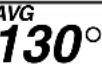 MAG MAG | Average heading. You can reset this value with the ▶/CLEAR key. See section 2.6. |
 COG COG | Course over ground (COG). COG is the direction of movement relative to the earth. GPS information is required. |
2.5 Unlocked and Locked Heading Modes
In the unlocked mode, the digital display shows the current heading, true or magnetic, and the pointer is at zero. The unit always starts up in the unlocked mode.
In the locked mode, the operator sets a fixed (locked) heading, with the arrow keys. The digital display shows either locked heading or current heading, depending on calibration setting. The pointer shows the difference between the locked heading and the actual course being steered; that is, heading error.

flowchart
graph TD
    A["Unlocked heading"] --> B["135° MAG"]
    B --> C["ENT"]
    C --> D["0° LOCK MAG"]
    D --> E["Locked heading"]
You can switch between the unlock mode and the locked mode with the ENT key.
Setting locked heading
When you enter the locked mode, the current heading becomes the locked heading. Then, the digital display shows locked heading or current heading, depending on the setup1 menu setting. To change the locked heading, use the ◀ key to shift the heading leftward.

2.6 Resetting Average Heading Indication
The average heading indication can be reset with the ▶/CLEAR key. Press and hold down the key. A short beep sounds, the indication flashes twice and then a long beep sounds to indicate that resetting is completed.
3. FI-506 RUDDER
The FI-506 Rudder displays rudder angle, in analog indication. The pointer shows the rudder position in real time. The instrument's scale range is -40^ to +40^ about zero.
The FI-506 operates in real time, thus almost no action is required of the operator other than confirming the rudder angle and adjustment of the brilliance.
3.1 Operating Controls

3. FI-506 RUDDER
3.2 Turning the Power On/Off
To power the instrument, press the [ ]key. After the pointer moves to current rudder angle, release the key.
To power off the instrument, press and hold down the [ ]key until the backlight goes off.
3.3 Adjusting Display Brilliance
Use the BRILL key to adjust the display brilliance. There are three levels of brilliance.
The brilliance will be the same on all units which are synchronized. (For how to synchronize units, see page 32.)
3.4 Calibrating Rudder Angle
You can calibrate the rudder indication to remove any deviation from actual and displayed rudder angles.
-
With the rudder centered, press the ◀ and ▶ keys together until the instrument starts beeping continuously. The beeping indicates you have correctly enabled the calibration mode.
-
Use the ◀ or ▶ key to move the pointer to the zero position.
-
Press ◀ and ▶ keys together again to save the setting and escape from the calibration mode.
4. MAINTENANCE,
TROUBLESHOOTING
This chapter provides the information necessary for keeping your equipment in good working order.
WARNING

Do not open the equipment.
Only qualified personnel should work inside the equipment.
4.1 Preventive Maintenance
Following the recommended procedures below will help maintain performance.
| Check item Check point Remedy | ||
| Cabling Check that all cabling is securely fastened and is free or rust and corrosion. | Reconnect if necessary. Replace if damaged. | |
| Cabinet Dust on cabinet Remove dust with a soft, lint-free cloth. | ||
| NOTICEDo not apply paint, anti-corrosive sealant or contact spray to coating or plastic parts of the equipment.Those items contain organic solvents that can damage coating and plastic parts, especially plastic connectors. | ||
4.2 Troubleshooting
If you feel the equipment is not functioning properly, follow the procedures in the table below to try to restore normal operation. If normal operation cannot be restored, do not attempt to check inside the cabinet. There are no user-serviceable parts inside.
Troubleshooting
| Problem Possible cause Remedy | ||
| Power cannot be turned on | • Power supply• Cabling disconnected or damaged. | • Check power supply.• Check cabling. |
| Power is on but no data | • Cable from sensor is damaged or disconnected. | • Check sensor. |
| Inaccurate data | • Electromagnetic field generating equipment is in operation.• Sensor is improperly aligned. | • Turn off all electromagnetic field generating equipment. Turn them on and off one by one. Check the display. Relocate offending equipment if necessary.• Check installation. |
5. INSTALLATION
NOTICE
Do not apply paint, anti-corrosive sealant or contact spray to coating or plastic parts of the equipment.
Those items contain organic solvents that can damage coating and plastic parts, especially plastic connectors.
5.1 Equipment Lists
Standard supply for FI-501 WIND ANGLE
| Name Type | Code No. Qty Remarks | ||||
| Display Unit FI-501 - 1 | |||||
| Wind Transducer FI-5001 - 1 | |||||
| Installation Materials | CP26-00100 000-011-739 1 set For display unit | See packing list at end of manual for details. | |||
| CP26-00201 001-026-600 | 1 set For wind transducer | ||||
| CP26-00300 000-010-511 | Select one. | 30 m cable, terminal box | |||
| CP26-00400 000-010-618 | 50 m cable, terminal box | ||||
Standard supply for FI-502 CH WIND ANGLE
| Name | Type | Code No. | Qty | Remarks |
| Display Unit | FI-502 | - | 1 | |
| Installation Materials | CP26-00500 000-011-742 | 1 set | See packing list at end of manual for details. | |
Standard supply for FI-505 COURSE PILOT
| Name | Type | Code No. | Qty | Remarks |
| Display Unit | FI-505 | - | 1 | |
| Installation Materials | CP26-00500 | 000-011-742 | 1 set | See packing list at end of manual for details. |
5. INSTALLATION
Standard supply for FI-506 RUDDER
| Name Type | Code No. Qty Remarks | ||
| Display Unit FI-506 - 1 | |||
| Installation Materials | CP26-00500 000-011-742 1 set | See packing list at end of manual for details. | |
Optional supply
| Name Type | Code No. Qty Remarks | |||
| Wind Transducer | FI-5001 | - | 1 set | For FI-502 |
| Terminal Box FI-5001 | 01-TERMINAL | 000-010-913 | 1 set For | FI-5001 |
| Cable Assy. | FI-50-DROP | 000-166-945-10 | 1 | |
| FI-50-CHAIN-0.3M | 000-166-949-10 | 1 | ||
| FI-50-CHAIN-5M | 000-166-951-10 | 1 | ||
| FI-50-CHAIN-1M | 000-166-950-10 | 1 | ||
| FI-50-CHAIN-10M | 000-166-952-10 | 1 | ||
| FI-50-CHAIN-20M | 000-166-953-10 | 1 | ||
| Flush Mount Kit | FI-50-FLUSH-KIT 000 | 00-010-619 | 1 set | |
| Installation Materials | CP26-00300 | 000-010-511 1 set | 30 m cable, for FI-5001 | |
| CP26-00400 | 000-010-618 | 1 set 50 m cable, for FI-5001 | ||
| Junction Box | FI-5002 | 000-010-765 | 1 set | See packing list at end of manual for details. |
5.2 Mounting
5.2.1 Wind Transducer FI-5001 (for FI-501, FI-502)
Installation site
Fix the transducer to the mounting mast so that its mounting base is parallel with the water line. Also, position the transducer so its leading edge faces the bow.
Mounting procedure
- Orient the mounting base as shown in the figure below, with the threaded part of the mounting base facing the bow. Fix the mounting base to the mast with four self-tapping screws (supplied).

Self-tapping Screw (4x20, 4 pcs.)

natural_image
Pure technical line drawing of a mechanical component with no text or symbols- Pass the connector on the transducer through the hole in the mounting base and then screw the cap on the transducer into the mounting base.
5. INSTALLATION
- Mate the connector at the rear of the transducer to cable assy. FI-50-SENSOR-30/50 (30 m or 50 m, supplied).

- As shown in the figure below, make a loop in the cable assy. Fix the cable to the mounting base with two cable ties (local supply).

- Pass the cable assy. through the mast and connect it to the FI-501/FI-502. If the connector of the cable cannot be passed through the mast (because mast diameter is too small), use the terminal box (supplied) to make the connection. For how to use the terminal box, see page 25.
5.2.2 Display unit
The display unit can be installed two ways: surface mount (two ways) or flush mount (optional kit required). This section covers surface mounting. For flush mounting, see the flush mounting instructions, issued separately.
Surface mount 1: Fix instrument from front panel
- Using the template at the back of this manual, open a mounting hole in the installation site.
- Detach the front panel together with the keypad assy. Attach sponge (supplied) to rear of display unit.
- Set the display unit to the mounting hole and fix it with four self-tapping screws (3×20, supplied).
- Attach the front panel and keypad assy. to the display unit.

5. INSTALLATION
Surface mount 2: Fix instrument from rear panel
-
Using the template at the back of this manual, open a mounting hole in the installation site.
-
Insert studs (M3x40, 2 pcs., supplied) in the holes shown below. (Use only the studs supplied.).

- Set the display unit to the mounting hole, inserting studs through respective holes. Fix the display unit with wing nuts (M3, supplied).

5.3 Wiring
5.3.1 Standalone configuration
For standalone configuration the junction box is not necessary; connect the instrument directly to the power supply.

Note: Turn on the display unit's terminal resistor. For the procedure, see page 33 (FI-501/502/505 or page 35 (FI-506)
Using the terminal box
As shown in the figure above, the display unit is connected to the wind transducer with the cable assy. FI-50-SENSOR-30/50. However, if the connector of the cable cannot be passed through the mast (because its diameter is too small), use the Terminal Box to make the connection.
Wire it as shown on the next page. The box is not waterproof; locate it out of areas subject to rain or water splash. The length of the cable between the FI-5001 and display units is maximum 50 m.
- Cut the connector from the FI-50-SENSOR-30/50 cable and pass the cable thru the mast.
- Fabricate the above-mentioned cables as shown below.

5. INSTALLATION
-
Unfasten two self-tapping screws to remove the cover of the terminal box.
-
Connect the cables to the terminal inside the terminal box, referring to the interconnection diagram. Bind wires with cable ties at the locations shown below.

- Fasten the cover with the screws removed at step 4. Use two self-tapping screws (M3×12, supplied) to fix the terminal box.

5.3.2 NMEA 2000 network configuration

flowchart
graph TD
    A["Wind Transducer FI-5001"] --> B["Cable Assy. FI-50-SENSOR-30/50 (30 m or 50 m)"]
    B --> C["DISP. UNIT FI-501/FI-502"]
    C --> D["DISP. UNIT FI-503/FI-504/FI-505/FI-506 (Instruments can be connected in any order.)"]
    C --> E["INSTRUMENTS CHAINED AS ABOVE"]
    C --> F["INSTRUMENTS CHAINED AS ABOVE"]
    C --> G["INSTRUMENTS CHAINED AS ABOVE"]
    C --> H["INSTRUMENTS CHAINED AS ABOVE"]
    C --> I["INSTRUMENTS CHAINED AS ABOVE"]
    C --> J["INSTRUMENTS CHAINED AS ABOVE"]
    C --> K["INSTRUMENTS CHAINED AS ABOVE"]
    C --> L["INSTRUMENTS CHAINED AS ABOVE"]
    C --> M["INSTRUMENTS CHAINED AS ABOVE"]
    C --> N["INSTRUMENTS CHAINED AS ABOVE"]
    C --> O["INSTRUMENTS CHAINED AS ABOVE"]
    C --> P["INSTRUMENTS CHAINED AS ABOVE"]
    C --> Q["INSTRUMENTS CHAINED AS ABOVE"]
    C --> R["INSTRUMENTS CHAINED AS ABOVE"]
    C --> S["INSTRUMENTS CHAINED AS ABOVE"]
    C --> T["INSTRUMENTS CHAINED AS ABOVE"]
    C --> U["INSTRUMENTS CHAINED AS ABOVE"]
    C --> V["INSTRUMENTS CHAINED AS ABOVE"]
    C --> W["INSTRUMENTS CHAINED AS ABOVE"]
    C --> X["INSTRUMENTS CHAINED AS ABOVE"]
    C --> Y["INSTRUMENTS CHAINED AS ABOVE"]
    C --> Z["INSTRUMENTS CHAINED AS ABOVE"]
    C --> AA["INSTRUMENTS CHAINED AS ABOVE"]
    C --> AB["INSTRUMENTS CHAINED AS ABOVE"]
    C --> AC["INSTRUMENTS CHAINED AS ABOVE"]
    C --> AD["INSTRUMENTS CHAINED AS ABOVE"]
    C --> AE["INSTRUMENTS CHAINED AS ABOVE"]
    C --> AF["INSTRUMENTS CHAINED AS ABOVE"]
    C --> AG["INSTRUMENTS CHAINED AS ABOVE"]
    C --> AH["INSTRUMENTS CHAINED AS ABOVE"]
    C --> AI["INSTRUMENTS CHAINED AS ABOVE"]
    C --> AJ["INSTRUMENTS CHAINED AS ABOVE"]
    C --> AK["INSTRUMENTS CHAINED AS ABOVE"]
    C --> AL["INSTRUMENTS CHAINED AS ABOVE"]
    C --> AM["INSTRUMENTS CHAINED AS ABOVE"]
    C --> AN["INSTRUMENTS CHAINED AS ABOVE"]
    C --> AO["INSTRUMENTS CHAINED AS ABOVE"]
    C --> AP["INSTRUMENTS CHAINED AS ABOVE"]
    C --> AQ["INSTRUMENTS CHAINED AS ABOVE"]
    C --> AR["INSTRUMENTS CHAINED AS ABOVE"]
    C --> AS["INSTRUMENTS CHAINED AS ABOVE"]
    C --> AT["INSTRUMENTS CHAINED AS ABOVE"]
    C --> AU["INSTRUMENTS CHAINED AS ABOVE"]
    C --> AV["INSTRUMENTS CHAINED AS ABOVE"]
    C --> AW["INSTRUMENTS CHAINED AS ABOVE"]
    C --> AX["INSTRUMENTS CHAINED AS ABOVE"]
    C --> AY["INSTRUMENTS CHAINED AS ABOVE"]
    C --> AZ["INSTRUMENTS CHAINED AS ABOVE"]
    C --> BA["INSTRUMENTS CHAINED AS ABOVE"]
    C --> BB["INSTRUMENTS CHAINED AS ABOVE"]
    C --> BC["INSTRUMENTS CHAINED AS ABOVE"]
    C --> BD["INSTRUMENTS CHAINED AS ABOVE"]
    C --> BE["INSTRUMENTS CHAINED AS ABOVE"]
    C --> BF["INSTRUMENTS CHAINED AS ABOVE"]
    C --> BG["INSTRUMENTS CHAINED AS ABOVE"]
    C --> BH["INSTRUMENTS CHAINED AS ABOVE"]
    C --> BI["INSTRUMENTS CHAINED AS ABOVE"]
    C --> BJ["INSTRUMENTS CHAINED AS ABOVE"]
    C --> BK["INSTRUMENTS CHAINED AS ABOVE"]
    C --> BL["INSTRUMENTS CHAINED AS ABOVE"]
    C --> BM["INSTRUMENTS CHAINED AS ABOVE"]
    C --> BN["INSTRUMENTS CHAINED AS ABOVE"]
    C --> BO["INSTRUMENTS CHAINED AS ABOVE"]
    C --> BP["INSTRUMENTS CHAINED AS ABOVE"]
    C --> BQ["INSTRUMENTS CHAINED AS ABOVE"]
    C --> BR["INSTRUMENTS CHAINED AS ABOVE"]
    C --> BS["INSTRUMENTS CHAINED AS ABOVE"]
    C --> BT["INSTRUMENTS CHAINED AS ABOVE"]
    C --> BU["INSTRUMENTS CHAINED AS ABOVE"]
    C --> BV["INSTRUMENTS CHAINED AS ABOVE"]
    C --> BW["INSTRUMENTS CHAINED AS ABOVE"]
    C --> BX["NMEA 2000 Backbone Cable (local supply)"]
    BX --> BY["FI-50X"] & BQ["NMEA 2000 Backbone Cable (local supply)"]
    BX --> BQ & BQN["JUNCTION BOX FI-5002"]
The total length of drop cables and backbone cables must be within 80 m.
5. INSTALLATION
Junction box (option)
The junction box is required when connecting NMEA 2000 network. This section covers wiring of the junction box. For how to mount the junction box, see its installation instructions, issued separately.

CN3 DROP - CN5 DROP and BACKBONE are socket-and-plug-type terminal blocks. Detach plug to connect wiring to it, by rocking it back and forth with your fingers. Remove approx. 6 mm of the sheath from the end of wires and twist wires. Loosen fixing screw in the plug, insert wire into hole and tighten fixing screw. Set plug to socket.

Terminal resistor
The illustration below show various system configurations and what units to activate the terminal resistor.
Smart sensor+FI-50x

Multiple FI-50 series instruments, FI-5002, drop cabling

flowchart
graph TD
    A["FI-50x"] --> B["FI-50x"]
    B --> C["FI-50x"]
    C --> D["FI-50x"]
    E["FI-5002"] --> F["•"]
Multiple FI-50 series instruments, FI-5002

flowchart
graph TD
    A["FI-50x"] --> B["FI-5002"]
    C["FI-50x"] --> B
    D["FI-50x"] --> B
    E["FI-50x"] --> B
Multiple FI-50 series instruments, multiple FI-5002

flowchart
graph LR
    A["FI-50x"] --> B["FI-5002"]
    C["FI-50x"] --> B
    D["FI-50x"] --> E["FI-5002"]
    F["FI-50x"] --> G["FI-5002"]
    H["FI-50x"] --> I["FI-5002"]
Multiple FI-50 series instruments, FI-5002, smart sensor

flowchart
graph TD
    A["Smart Sensor"] --> B["FI-50x"]
    B --> C["FI-50x"]
    C --> D["FI-50x"]
    B --> E["FI-5002"]
Multiple FI-50 series instruments, FI-5002, heading sensor, smart sensor

Multiple FI-50 series instruments, FI-5002, NMEA 2000 sensors

- = Terminal resistor ON
5. INSTALLATION
Turn on the terminal resistor in the junction box when the NMEA 2000 sensor(s) connected to it do not have a terminal resistor.

For how to turn on the terminal resistor in a FI-50 series instrument, see page 33 (FI-501//FI-502/FI-505) or page 35 (FI-506).
5.4 Setting Up
Your instrument is pre-programmed with factory default settings, which may or may not be suited to your vessel. Therefore, it is necessary to initialize the instrument for use with your vessel. This should be done immediately after completion of the installation.
Two sets of setup menus are provided: setup1 and setup2. The setup1 menu provides system parameters and setup2 has user settings.
The procedure for setting up the instruments is mainly the same; the only difference is the key names. You use the MODE key and the 3rd and 4th keys from the left to do the setting up.
5.4.1 Setting up FI-501/FI-502/FI-505
Setup1 menu
The setup1 menu optimizes the instrument for use on your vessel. Follow the procedure below to access and set the items on this menu.
- Press the 3rd and 4th keys from the left together momentarily. The first menu item for respective model appears, with current setting flashing.
- Press the MODE key to choose a menu item. Each press of the key changes the menu item in the sequence shown below.

flowchart
graph TD
    A["CAL\nF\nWind data selection"] --> B["CAL\ntd\nWind input selection"]
    B --> C["CAL\nkt\nWind speed unit"]
    C --> D["CAL\n1.0\nWind speed adjustment"]
    D --> E["CAL\n0°\nWind angle offset"]
    E --> F["CAL\nALI\nPointer alignment"]
    F --> G["CAL\nMAG\nHeading ref.\non next tack"]
    G --> H["CAL VMG\n3\nVMG response"]
    H --> I["CAL b 1.0\nBoat speed response"]
    I --> J["CAL P\n4\nPointer response"]
    J --> K["CAL S\n3\nWind speed response"]
    K --> G
Setup1 menu items for FI-501, FI-502

flowchart
graph TD
    A["Magnetic/true selection"] --> B["Pointer alignment"]
    B --> C["Heading indication"]
    C --> D["Course over Ground response"]
    D --> E["Pointer response"]
    E --> F["Heading response"]
Setup1 menu items for FI-505
5. INSTALLATION
- Use the 3rd and 4th keys to set a value or select option.
3rd key: Decrement value.
4th key: Increment value or select option.
-
To continue, press the MODE key to select another item.
-
To save settings and restore normal operation, press the 3rd and 4th keys together.
Setup1 menu items for FI-501, FI-502
| Display Function | Setting range or options | Default setting | |
 | Select source of wind data. Select "r" for second unit. | F: For FI-5001, r: repeater | F |
 | Select source of wind input. td: Transducer, Fr: FURUNO repeater | td | |
 | Select wind speed unit. kt, m/s kt | ||
 | Set wind speed adjustment. 0.3 - 2.5 1.0 | ||
 | Set wind angle offset. 0 | ° - 359° | 0 |
 | Align pointer to zero. Operate the VMG or TACK/CLEAR key until the pointer is at zero. | ||
 | Set wind speed response. The lower the value the faster the response. | 0 - 12 3 | |
 | Set wind pointer response. The lower the value the faster the response. | 0 - 12 4 | |
 | Set boat speed adjustment (for VMG). | 0.3 - 2.5 1.0 | |
 | Set velocity made good response. The lower the value the faster the response. | 0 - 12 3 | |
 | Set heading reference on next tack. | MAG(netic), TRUE MAG | |
Setup1 menu items for FI-505
| Menu item(in sequential order) | Function | Setting range or options | Default setting |
 | Select bearing reference. | MAG: Magnetic, TRUE: True | MAG |
 | Align pointer to zero. Operate the ◀ key or the ▶/CLEAR key until the pointer is at zero. | ||
 | Enables/disables use of locked heading.Choose LOC to enable locked heading. | LOC: Locked, Cur: Current | LOC |
 | Set heading response. The lower the setting the faster the response to change in heading. | 0 - 12 0 | |
 | Set pointer response. The lower the setting the faster the pointer responds. | 0 - 12 0 | |
 | Set course over ground response. The lower the setting the higher the response to changed in course over ground. | 0 - 12 0 |
Setup2 menu
The setup2 menu contains items which once preset do not require frequent adjustment. This menu is mostly operated the same as the setup1 menu. The only difference is how long the 3rd and 4th keys are pressed to activate the menu.
- Press the 3rd and 4th keys together (about 5-6 seconds) until the software version screen for CPU1 appears. (See the illustration below.)
- Press the MODE key to select a menu item. Each press of the key changes the menu item in the sequence shown in the illustration at the top of the next page.

flowchart
graph LR
    A["CAL CAL\nXXX\nSoftware ver. no.\n(CPU1)"] --> B["XXX\nSoftware ver. no.\n(CPU2)"]
    B --> C["CAL\nbE1"]
    C --> D["Key beep Auto brilliance"]
    D --> E["CAL\nbr1"]
    E --> F["Setup1 menu"]

flowchart
graph TD
    A["Factory defaults"] --> B["CAL FAO"]
    B --> C["Calcium"]
    C --> D["dE0 Demo"]
    D --> E["Calcium Sy1"]
    E --> F["Synchronization"]
    F --> G["Terminal resistor"]
    H["MODE"] --> I["Calcium"]
    I --> J["rE0"]
    style A fill:#f9f,stroke:#333
    style B fill:#ccf,stroke:#333
    style C fill:#cfc,stroke:#333
    style D fill:#fcc,stroke:#333
    style E fill:#cff,stroke:#333
    style F fill:#ffc,stroke:#333
    style G fill:#cfc,stroke:#333
    note right of A: XXX=program and program ver. nos.
- Use the 4th key to select ON or OFF as applicable.
- To continue, press the MODE key to select another item.
- To save settings and restore normal operation, press the 3rd and 4th keys together.
Setup2 menu items
| Display Function Options | Default setting | ||
 | Software version of CPU1.XX=program no. and x=programversion no. | - | - |
 | Software version of CPU2.XX=program no. and x=programversion no | - | - |
 | Key beep on/off. 1: ON, 0: OFF 1(ON) | ||
 | Adjust brilliance automaticallywith environment. | 1: ON, 0: OFF 1(ON) | |
 | Enable/disable access to thesetup1 menu. | 1: ON, 0: OFF 1(ON) | |
CAL | Terminal resistor on/off. 1: ON, 0: OFF 0(OFF) | ||
CAL | Turn on/off synchronization ofFI-50 series instruments. | 1: ONSynchronize all FI-50instruments having thissetting.A: Synchronize FI-50instruments havingthis setting.b: Synchronize FI-50instruments havingthis setting.0: Turn offsynchronization. | 1(ON) |
 | Demo mode on/off.To turn on/off, press the 4th keyabout four seconds. | 1: ON, 0: OFF 0(OFF) | |
CAL | Restore factory defaults.To restore factory defaults,press and hold down the 4th keyuntil “0” is replaced with “1” andthen press the key again withintwo seconds. | 1: ON, 0: OFF 0(OFF) | |
5.4.2 Setting up FI-506
Rudder calibration
You can apply an offset to the rudder indication to remove any deviation from actual and displayed rudder angles.
- With the rudder centered, press the ◀ and ▶ keys together until the instrument starts beeping continuously. The beeping indicates you have correctly enabled the calibration mode.
- Use the ◀ and ▶ keys to move the pointer to the zero position.
- Press the ◀ and ▶ keys together again to save the setting and escape from the calibration mode.
Terminal resistor on/off
The terminal resistor enables/disables connection of the FI-506 to an NMEA 2000 network, and it is disabled at the factory. To turn the resistor on or off, press and hold down the BRILL and ◀ keys together until you hear a beep. Then, press the ▶ key to turn the resistor on or off. The number of beeps indicates ON or OFF. Two beeps for ON, three beeps for OFF. Press the BRILL and ◀ keys together to save the setting and return to normal operation. A beep sounds upon completion.
Synchronization on/off
The data shared within the FI-50 instruments series can be synchronized, so that all data agrees. You can turn synchronization of all data on or off, or synchronize data by group, A and/or B. For group synchronization, instruments having like group synchronization settings are synchronized.
To set synchronization, press and hold down the BRILL and ▶ keys together until you hear a beep. Then, press the ▶ key to select applicable synchronization setting. The number of beeps and beep duration indicate the setting as shown below. Press the BRILL and ▶ keys together to save the setting and return to normal operation. A beep sounds upon completion.
ON: Beep ^1 OFF^1 Beep^1 A: Beep ^1 OFF^1 Beep^3 B: Beep ^3 OFF^1 Beep^1 OFF^1 Beep^1 OFF^1 Beep^1 OFF: Beep ^3 OFF^2 Beep^3 OFF^2 Beep^3 ^1 200 ms, ^2 500 ms, ^*3 1000 ms
Factory defaults
Press the ⏻ and BRILL keys together until you hear a beep, indicating completion. Press the same keys again to return to normal operation.
SPECIFICATIONS OF
FI-501 WIND ANGLE
FI-502 CLOSE HAULED WIND ANGLE
1 GENERAL
1.1 Display Analog and segment LCD
1.2 Display Content Wind angle, wind speed, VMG, tack heading
1.3 Analog Meter Range ±180° (FI-501), ±60° (FI-502)
1.4 Analog Meter Accuracy ±10° (FI-501), ±5° (FI-502)
1.5 I/O Port - NMEA 2000: 2 ports
- Wind sensor input: 1 port
2 WIND TRANSDUCER
2.1 Wind Angle Measurement Range 0-360°
2.2 Wind Direction Measurement Accuracy ±10^
2.3 Wind Speed Measurement Range 0.9 kt – 90 kt
2.4 Wind Speed Measurement Accuracy Up to 20 kt: kt: ±1 kt, More than 20 kt: ±5%
2.5 Response Within one second
3 JUNCTION BOX (OPTION)
3.1 No. of I/O ports
NMEA 2000 Device 6 ports
NMEA 2000 Backbone 2 ports
4 POWER SUPPLY AND POWER CONSUMPTION
4.1 Display Unit 12 VDC, less than 0.1 A
3.2 Junction Box 12 VDC, less than 1 A, max. 2A connectable
4.3 Wind Transducer 12 VDC, less than 50 mA
5 ENVIRONMENTAL CONDITIONS
5.1 Useable Temperature Range -15^ - +55^
5.2 Relative Humidity Less than 95% (+40°C)
5.3 Waterproofing Display Unit IP56 Junction Box IPX0
5.4 Vibration - 2 Hz-5 Hz and up to 13.2 Hz with an excursion of ±1 mm ±10% (7 m/s ^2 maximum acceleration at 13.2 Hz); - above 13.2 Hz and up to 100 Hz with a constant maximum acceleration of 7 m/s ^2
6 COATING COLOR
6.1 Display Unit N2.5
6.2 Junction Box N2.5
SPECIFICATIONS OF FI-505 COURSE PILOT
1 GENERAL
1.1 Display Analog and digital LCD
1.2 Display Content Heading
1.3 Analog Meter Display Range ±30°
1.4 Analog Meter Display Accuracy ±3°
1.5 I/O Port NMEA 2000, 2 ports
2 JUNCTION BOX (OPTION)
2.1 No. of I/O ports
NMEA 2000 Device 6 ports
NMEA 2000 Backbone 2 ports
3 POWER SUPPLY AND POWER CONSUMPTION
3.1 Display Unit
12 VDC, less than 0.1 A
3.2 Junction Box
12 VDC, less than 1 A, max. 2A connectable
4 ENVIRONMENTAL CONDITIONS
4.1 Useable Temperature Range
-15^ - +55^
4.2 Relative Humidity
Less than 95% (+40°C)
4.3 Waterproofing Display Unit Junction Box
IP56
IPX0
4.4 Vibration
- 2 Hz-5 Hz and up to 13.2 Hz with an excursion of ±1 mm ±10% (7 m/s ^2 maximum acceleration at 13.2 Hz); - above 13.2 Hz and up to 100 Hz with a constant maximum acceleration of 7 m/s ^2
5 COATING COLOR
5.1 Display Unit
5.2 Junction Box
N2.5
N2.5
SPECIFICATIONS OF FI-506 RUDDER
1 GENERAL
1.1 Display Analog
1.2 Analog Meter Display Range ±40°
1.3 Analog Meter Display Accuracy ±5°
1.4 I/O Port NMEA 2000, 2 ports
2 JUNCTION BOX (OPTION)
2.1 No. of I/O ports
NMEA 2000 Device 6 ports
NMEA 2000 Backbone 2 ports
3 POWER SUPPLY AND POWER CONSUMPTION
3.1 Display Unit 12 VDC, less than 0.1 A
3.2 Junction Box 12 VDC, less than 1 A, max. 2A connectable A
4 ENVIRONMENTAL CONDITIONS
4.1 Useable Temperature Range -15^ - +55^
4.2 Relative Humidity Less than 95% (+40°C)
4.3 Waterproofing
Display Unit
Junction Box
IP56
IPX0
4.4 Vibration - 2 Hz-5 Hz and up to 13.2 Hz with an excursion of ±1 mm ±10% (7 m/s maximum acceleration at 13.2 Hz);
- above 13.2 Hz and up to 100 Hz with constant maximum acceleration of 7 m/s^2
5 COATING COLOR
5.1 Display Unit N2.5
5.2 Junction Box N2.5
NAME OUTLINE QTYDESCRIPTION CODE No
| ケープル組品CABLE ASSY. | FI - 50- DROP | 1 | |
| 000-166-945-10 | |||
| 図書 DOCUMENT | |||
| 内部終端ノ設定INTERNAL RESISTOR SETTING | C72-00705-* | 1 | |
| 000-168-501-1* | |||
| 取扱説明書OPERATOR'S MANUAL | OM*-72660-* | 1 | |
| 000-166-981-1** | |||
| 操作要領書OPERATOR'S GUI DE | OS*-72660-* | 1 | |
| 000-167-289-1** | |||
| 表示部MONI TOR UNI T |  | FI-501 | 1 |
| 000-011-738-00 |
- SAFETY INSTRUCTIONS
- Safety instructions for the operator
- Safety instructions for the installer
- Warning Label
- FI-505 COURSE PILOT 9
- FI-506 RUDDER....13
- MAINTENANCE,TROUBLESHOOTING 15
- INSTALLATION....17
- SPECIFICATIONS SP-1
- PACKING LIST A-1
- OUTLINE DRAWINGS......D-1
- INTERCONNECTION DIAGRAM S-1
- A Word to the Owner of the FI-501, FI-502, FI-505, FI-506
- Features
- FI-501, FI-502
- FI-505
- FI-506
- FI-501 WIND ANGLE
- FI-502 CLOSE HAULED WIND ANGLE
- Operating Controls
- Turning the Power On/Off
- Adjusting Brilliance and Contrast
- Display Layout
- Selecting a Display
- Selecting Apparent or True Wind Angle, Wind Speed
- Displaying Velocity Made Good (VMG) Information
- Displaying Tack Angle
- Alarms
- When an alarm is violated:
- FI-505 COURSE PILOT
- Operating Controls
- Turning the Power On/Off
- Adjusting Brilliance and Contrast
- Selecting a Display
- Unlocked and Locked Heading Modes
- Setting locked heading
- Resetting Average Heading Indication
- FI-506 RUDDER
- Operating Controls
- Turning the Power On/Off
- Adjusting Display Brilliance
- Calibrating Rudder Angle
- MAINTENANCE,
- TROUBLESHOOTING
- WARNING
- Preventive Maintenance
- Troubleshooting
- INSTALLATION
- NOTICE
- Equipment Lists
- Mounting
- Wind Transducer FI-5001 (for FI-501, FI-502)
- Installation site
- Mounting procedure
- Display unit
- Surface mount 1: Fix instrument from front panel
- Surface mount 2: Fix instrument from rear panel
- Wiring
- Standalone configuration
- Using the terminal box
- NMEA 2000 network configuration
- Junction box (option)
- Terminal resistor
- Setting Up
- Setting up FI-501/FI-502/FI-505
- Setup1 menu
- Setup2 menu
- Setting up FI-506
- Rudder calibration
- Terminal resistor on/off
- Synchronization on/off
- Factory defaults
- SPECIFICATIONS OF
- FI-501 WIND ANGLE
- GENERAL
- WIND TRANSDUCER
- JUNCTION BOX (OPTION)
- POWER SUPPLY AND POWER CONSUMPTION
- ENVIRONMENTAL CONDITIONS
- COATING COLOR
- SPECIFICATIONS OF FI-505 COURSE PILOT
- JUNCTION BOX (OPTION)
- POWER SUPPLY AND POWER CONSUMPTION
- ENVIRONMENTAL CONDITIONS
- COATING COLOR
- SPECIFICATIONS OF FI-506 RUDDER
Brand : FURUNO
Model : FI-502 CH Wind Angle
Category : Navigation instrument