OMNI-122 - Digital decoder Atlona - Free user manual and instructions
Find the device manual for free OMNI-122 Atlona in PDF.


| Product Type | Networked AV Decoder, Dual-Channel |
| Model | AT-OMNI-122 |
| Video Input | 2 x HDMI, up to 4K/UHD (3840x2160@30Hz, 4096x2160@24Hz) |
| Video Codec | SMPTE VC-2 |
| Video Compression | Sub-frame latency, chroma subsampling 4:4:4, 4:2:2, color depth 8/10/12-bit |
| Audio Support | LPCM 2.0/5.1/7.1, Dolby Digital, Dolby TrueHD, DTS-HD MA, HDMI pass-through, Analog 2-channel balanced input/output, AES67 |
| Control Interface | RS-232 (2 ports), IR pass-through, TCP proxy, AMS (Atlona Management System) |
| Network Interface | 2 x RJ45 (10/100/1000 Mbps), PoE (802.3af), DHCP or Static IP |
| Encryption | AES-128 (selectable) |
| Forward Error Correction | SMPTE 2022-5, configurable matrix (up to 20x20) |
| Video Wall Support | Yes, with bezel compensation and rotation |
| Dimensions (H x W x D) | 34 mm x 208 mm x 112 mm (1.34 in x 8.19 in x 4.41 in) |
| Weight | 0.7 kg (1.54 lb) |
| Power Supply | PoE (IEEE 802.3af) or optional 48V DC, 0.83 A (AT-PS-48083-C) |
| Power Consumption | ~13 W (without analog audio), higher with analog audio |
| Operating Temperature | 0°C to 50°C (32°F to 122°F) |
| Humidity | 20% to 90% (non-condensing) |
| Certifications | CE, FCC Class A, cULus, RoHS |
| Warranty | 10 years (hardware purchased on or after June 1, 2013) |
| Maintenance | Clean only with a dry cloth; no user-serviceable parts inside |
| Safety | Do not expose to rain/moisture; use only attachments specified by Atlona; unplug during lightning storms |
| Spare Parts & Repairability | Refer all servicing to qualified personnel; power supply and mounting brackets are available separately |
| General Information | Supports redundant streams, video wall, slate/logo insertion, text scrolling, 802.1X authentication |
Frequently Asked Questions - OMNI-122 Atlona
User questions about OMNI-122 Atlona
0 question about this device. Answer the ones you know or ask your own.
Ask a new question about this device
Download the instructions for your Digital decoder in PDF format for free! Find your manual OMNI-122 - Atlona and take your electronic device back in hand. On this page are published all the documents necessary for the use of your device. OMNI-122 by Atlona.
USER MANUAL OMNI-122 Atlona
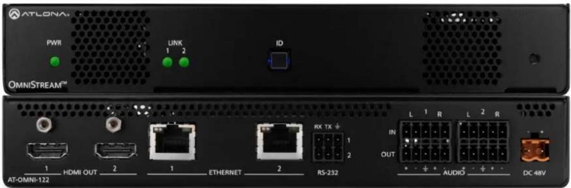
Networked AV Decoder
| VLO-OWID:155 | |||||||||
| HOME ONLY | 1 | EITHERE | K2-3J5 | VTDQ | DC 4EA | ||||
AT-OMNI-121
Atlona Manuals
AT-OMNI-122
Networked AV
Version Information
| Version Release Date Notes | ||
| 1 04/17 Initial release | ||
| 2 06/17 New enclosure, documentation updates: AMS interface; front-panel buttons, decoder set tab | ||
| 3 12/17 Video wall configuration plus bezel compensation, slate / logo insertion, text insertion, redundancy grace period for IP input changes | ||
| 4 05/18 Updated to reflect AMS 2.0 | ||
| 5 07/18 Includes updates to 1.2.1 firmware; AMS updates | ||
Welcome to Atlona!
Thank you for purchasing this Atlona product. We hope you enjoy it and will take a extra few moments to register your new purchase.
Registration only takes a few minutes and protects this product against theft or loss. In addition, you will receive notifications of product updates and firmware. Atlona product registration is voluntary and failure to register will not affect the product warranty.
To register your product, go to http://www.atlona.com/registration
Sales, Marketing, and Customer Support
Main Office
Atlona Incorporated
70 Daggett Drive
San Jose, CA 95134
United States
Office: +1.877.536.3976 (US Toll-free)
Office: +1.408.962.0515 (US/International)
Sales and Customer Service Hours
Monday - Friday: 6:00 a.m. - 4:30 p.m. (PST)
http://www.atlona.com/
International Headquarters
Atlona International AG
Ringstrasse 15a
8600 Dübendorf
Switzerland
Office: +41 43 508 4321
Sales and Customer Service Hours
Monday - Friday: 09:00 - 17:00 (UTC +1)
Operating Notes
- The Atlona Management System (AMS) is a free downloadable application from Atlona that provides network configuration assistance for this product. This application is available only for the Windows® Operating System and can be downloaded from the Atlona web site.

IMPORTANT: Visit http://www.atlona.com/product/AT-OMNI-121 and http://www.atlona.com/product/AT-OMNI-122 for the latest firmware updates and User Manual.
©2018 Atlona, Inc. All Rights Reserved. All trademarks are the property of their respective owners. Atlona reserves the right to make changes to the hardware, packaging, and documentation without notice.
Atlona, Inc. ("Atlona") Limited Product Warranty
Coverage
Atlona warrants its products will substantially perform to their published specifications and will be free from defects in materials and workmanship under normal use, conditions and service.
Under its Limited Product Warranty, Atlona, at its sole discretion, will either:
- repair or facilitate the repair of defective products within a reasonable period of time, restore products to their proper operating condition and return defective products free of any charge for necessary parts, labor and shipping.
OR
- replace and return, free of charge, any defective products with direct replacement or with similar products deemed by Atlona to perform substantially the same function as the original products.
OR
- refund the pro-rated value based on the remaining term of the warranty period, not to exceed MSRP, in cases where products are beyond repair and/or no direct or substantially similar replacement products exist.
Repair, replacement or refund of Atlona products is the purchaser's exclusive remedy and Atlona liability does not extend to any other damages, incidental, consequential or otherwise.
This Limited Product Warranty extends to the original end-user purchaser of Atlona products and is non-transferrable to any subsequent purchaser(s) or owner(s) of these products.
Coverage Periods
Atlona Limited Product Warranty Period begins on the date of purchase by the end-purchaser. The date contained on the end-purchaser 's sales or delivery receipt is the proof purchase date.
Limited Product Warranty Terms – New Products
• 10 years from proof of purchase date for hardware/electronics products purchased on or after June 1, 2013.
• 3 years from proof of purchase date for hardware/electronics products purchased before June 1, 2013.
• Lifetime Limited Product Warranty for all cable products.
Limited Product Warranty Terms - Refurbished (B-Stock) Products
- 3 years from proof of purchase date for all Refurbished (B-Stock) hardware and electronic products purchased on or after June 1, 2013.
Remedy
Atlona recommends that end-purchasers contact their authorized Atlona dealer or reseller from whom they purchased their products. Atlona can also be contacted directly. Visit www.atlona.com for Atlona's contact information and hours of operation. Atlona requires that a dated sales or delivery receipt from an authorized dealer, reseller or end-purchaser is provided before Atlona extends its warranty services. Additionally, a return merchandise authorization (RMA) and/or case number, is required to be obtained from Atlona in advance of returns.
Atlona requires that products returned are properly packed, preferably in the original carton, for shipping. Cartons not bearing a return authorization or case number will be refused. Atlona, at its sole discretion, reserves the right to reject any products received without advanced authorization. Authorizations can be requested by calling 1-877-536-3976 (US toll free) or 1-408-962-0515 (US/international) or via Atlona's website at www.atlona.com.
Exclusions
This Limited Product Warranty excludes:
- Damage, deterioration or malfunction caused by any alteration, modification, improper use, neglect, improper packaging or shipping (such claims must be presented to the carrier), lightning, power surges, or other acts of nature.
Atlona, Inc. ("Atlona") Limited Product Warranty
- Damage, deterioration or malfunction resulting from the installation or removal of this product from any installation, any unauthorized tampering with this product, any repairs attempted by anyone unauthorized by Atlona to make such repairs, or any other cause which does not relate directly to a defect in materials and/or workmanship of this product.
- Equipment enclosures, cables, power supplies, batteries, LCD displays, and any accessories used in conjunction with the product(s).
- Products purchased from unauthorized distributors, dealers, resellers, auction websites and similar unauthorized channels of distribution.
Disclaimers
This Limited Product Warranty does not imply that the electronic components contained within Atlona's products will not become obsolete nor does it imply Atlona products or their electronic components will remain compatible with any other current product, technology or any future products or technologies in which Atlona's products may be used in conjunction with. Atlona, at its sole discretion, reserves the right not to extend its warranty offering in instances arising outside its normal course of business including, but not limited to, damage inflicted to its products from acts of god.
Limitation on Liability
The maximum liability of Atlona under this limited product warranty shall not exceed the original Atlona MSRP for its products. To the maximum extent permitted by law, Atlona is not responsible for the direct, special, incidental or consequential damages resulting from any breach of warranty or condition, or under any other legal theory. Some countries, districts or states do not allow the exclusion or limitation of relief, special, incidental, consequential or indirect damages, or the limitation of liability to specified amounts, so the above limitations or exclusions may not apply to you.
Exclusive Remedy
To the maximum extent permitted by law, this limited product warranty and the remedies set forth above are exclusive and in lieu of all other warranties, remedies and conditions, whether oral or written, express or implied. To the maximum extent permitted by law, Atlona specifically disclaims all implied warranties, including, without limitation, warranties of merchantability and fitness for a particular purpose. If Atlona cannot lawfully disclaim or exclude implied warranties under applicable law, then all implied warranties covering its products including warranties of merchantability and fitness for a particular purpose, shall provide to its products under applicable law. If any product to which this limited warranty applies is a “Consumer Product” under the Magnuson-Moss Warranty Act (15 U.S.C.A. §2301, ET SEQ.) or other applicable law, the foregoing disclaimer of implied warranties shall not apply, and all implied warranties on its products, including warranties of merchantability and fitness for the particular purpose, shall apply as provided under applicable law.
Other Conditions
Atlona's Limited Product Warranty offering gives legal rights, and other rights may apply and vary from country to country or state to state. This limited warranty is void if (i) the label bearing the serial number of products have been removed or defaced, (ii) products are not purchased from an authorized Atlona dealer or reseller. A comprehensive list of Atlona's authorized distributors, dealers and resellers can be found at www.atlona.com.
Important Safety Information
CAUTION
RISK OF ELECTRIC SHOCK
DO NOT OPEN
CAUTION: TO REDUCT THE RISK OF
ELECTRIC SHOCK
DO NOT OPEN ENCLOSURE OR EXPOSE
TO RAIN OR MOISTURE
NO USER-SERVICEABLE PARTS
INSIDE REFER SERVICING TO
QUALIFIED SERVICE PERSONNEL.

The exclamation point within an equilateral triangle is intended to alert the user to the presence of important operating and maintenance instructions in the literature accompanying the product.

The information bubble is intended to alert the user to helpful or optional operational instructions in the literature accompanying the product.
- Read these instructions.
- Keep these instructions.
- Heed all warnings.
- Follow all instructions.
- Do not use this product near water.
- Clean only with a dry cloth.
- Do not block any ventilation openings. Install in accordance with the manufacturer's instructions.
-
Do not install or place this product near any heat sources such as radiators, heat registers, stoves, or other apparatus (including amplifiers) that produce heat.
-
Do not defeat the safety purpose of a polarized or grounding-type plug. A polarized plug has two blades with one wider than the other. A grounding type plug has two blades and a third grounding prong. The wide blade or the third prong are provided for your safety. If the provided plug does not fit into your outlet, consult an electrician for replacement of the obsolete outlet.
- Protect the power cord from being walked on or pinched particularly at plugs, convenience receptacles, and the point where they exit from the product.
- Only use attachments/accessories specified by Atlona.
- To reduce the risk of electric shock and/or damage to this product, never handle or touch this unit or power cord if your hands are wet or damp. Do not expose this product to rain or moisture.
- Unplug this product during lightning storms or when unused for long periods of time.
- Refer all servicing to qualified service personnel. Servicing is required when the product has been damaged in any way, such as power-supply cord or plug is damaged, liquid has been spilled or objects have fallen into the product, the product has been exposed to rain or moisture, does not operate normally, or has been dropped.
CE
FC
cULus
RoHS
CCC
√
FCC Statement

FCC Compliance and Advisory Statement: This hardware device complies with Part 15 of the FCC rules. Operation is subject to the following two conditions: 1) this device may not cause harmful interference, and 2) this device must accept any interference received including interference that may cause undesired operation. This equipment has been tested and found to comply with the limits for a Class A digital device, pursuant to Part 15 of the FCC Rules. These limits are designed to provide reasonable protection against harmful interference in a commercial installation. This equipment generates, uses, and can radiate radio frequency energy and, if not installed or used in accordance with the instructions, may cause harmful interference
to radio communications. However there is no guarantee that interference will not occur in a particular installation. If this equipment does cause harmful interference to radio or television reception, which can be determined by turning the equipment off and on, the user is encouraged to try to correct the interference by one or more of the following measures: 1) reorient or relocate the receiving antenna; 2) increase the separation between the equipment and the receiver; 3) connect the equipment to an outlet on a circuit different from that to which the receiver is connected; 4) consult the dealer or an experienced radio/TV technician for help. Any changes or modifications not expressly approved by the party responsible for compliance could void the user's authority to operate the equipment. Where shielded interface cables have been provided with the product or specified additional components or accessories elsewhere defined to be used with the installation of the product, they must be used in order to ensure compliance with FCC regulations.
Table of Contents
Introduction 9
Features 9
Package Contents 9
Panel Description 10
AT-OMNI-121 10
AT-OMNI-122 11
Installation 12
RS-232 Connections 12
IR Connections 13
Audio Connectors 15
Connection Instructions 17
Connection Diagram 18
Configuration 19
Discovery using AMS 19
Accessing Decoders in AMS 19
Configuring a Static IP Address 22
Basic Operation 23
LED Indicators 23
Rebooting OmniStream 24
ID Button 24
Broadcast Messaging 24
Reset to Factory-Default Settings. 24
Unicast Mode 25
Multicast Mode 27
Configuring Audio Output 29
De-embedding Audio 29
Embedding Audio 30
Control Using RS-232 Commands 31
Triggering Stored Commands 31
Using TCP Proxy 31
802.1X Authentication 32
EAP-TLS Protocol 33
PEAP/MSCHAPv2 Protocol 35
AES67 Audio 37
IR Configuration 38
Scrambling 40
Standard Method 40
Using the Virtual Matrix 41
Setting the Video Mode 43
Slate / Logo Insertion 44
Deleting Slates / Logos 45
Text Insertion 46
Creating Video Walls 48
Bezel Compensation 54
Using Velocity ^TM 55
Configuring Redundant Streams 63
Redundancy Grace Period 64
The AMS Interface 65
Device Info page 65
SAP page 68
IP Input page 69
HDMI Output page 71
Output 71
Video Optimization 75
Serial page 76
Table of Contents
| Serial Port 76 | |
| Serial Configuration 77 | |
| Command | 78 |
| Text page 79 | |
| Color | 80 |
| Location 80 | |
| Size 80 | |
| Logo page 81 | |
| PTP page 83 | |
| Network page 84 | |
| The Virtual Matrix 85 |
Appendix
88
Updating the Firmware 88
FEC Details 90
Matrix Size, Overhead, and Latency 90
FEC and Video Bitrate 90
FEC, Latency, and Lip Sync 91
Mounting Instructions 92
Rack Tray for OmniStream 93
Specifications 94
Introduction
The Atlona OmniStream™ 121 (AT-OMNI-121) is a networked AV decoder for one HDMI source up to 4K/UHD, plus embedded audio and RS-232 control. The Atlona OmniStream™ 122 (AT-OMNI-122) adds a second channel of encoding for two HDMI sources up to 4K/UHD and RS-232 control and can deliver duplicate AV streams to two networks for full system redundancy in mission-critical applications. OmniStream features SMPTE VC-2 compression for critical-quality video applications, with extremely low, sub-frame latency from encode to decode. It also includes selectable AES-128 encryption and SMPTE 2022-5 Forward Error Correction (FEC) for robust AV distribution spanning multiple networks. Both OmniStream decoders are housed in compact enclosures that easily fit into a half RU space. They can be powered over the network through Power over Ethernet (PoE) or optionally from local AC power.
OmniStream was engineered from the ground up at Atlona to deliver the performance and dependability of traditional AV distribution, with the virtually unlimited scalability and cost efficiency of integrating over data networks. It addresses the many challenges AV and IT integrators encounter with implementing networked AV systems, while delivering immediate and long-term ROI to end users in enterprises and other organizations
Features
OmniStream Single-Channel Decoder
• Single-channel AV decoder for HDMI up to 4K/UHD
- Redundancy capabilities for mission critical applications
- SMPTE VC-2 compression
- RS-232 control
- Selectable AES-128 encryption
- SMPTE 2022-5 FEC
- Powered using PoE or optional external 48V DC power supply
OmniStream Dual-Channel Decoder
• Dual-channel AV decoder for HDMI up to 4K/UHD
- Redundancy capabilities for mission critical applications
- SMPTE VC-2 compression
- RS-232 control
• Audio embedding / de-embedding
- Selectable AES-128 encryption
- SMPTE 2022-5 (FEC)
- Powered using PoE or optional external 48V DC power supply
Package Contents
OmniStream Single-Channel Decoder
1 x AT-OMNI-121
1 x Phoenix terminal block, 6-pin (push spring)
1 x Wall/table mounting brackets
4 x Rubber feet
1 x Installation Guide
OmniStream Dual-Channel Decoder
1 x AT-OMNI-122
1 x Phoenix terminal block, 6-pin (push spring)
1 x Wall/table mounting brackets
4 x Rubber feet
1 x Installation Guide
Panel Description
AT-OMNI-121
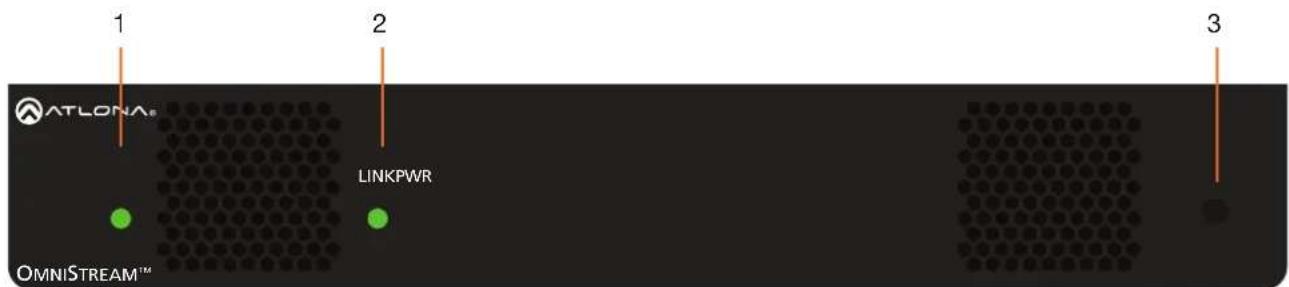
Front
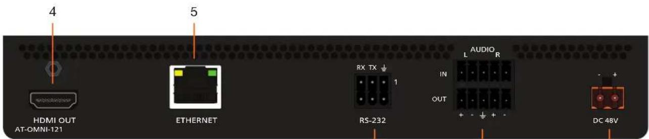
Rear
6 RS-232
Use the included Phoenix terminal block to connect an RS-232 device to this port. The bottom three pins support IR pass-through. Refer to IR Connections (page 13) for more information.
7 AUDIO
Connect the included Phoenix terminal blocks to embed audio on the output stream and/or connect to an audio output device.
8 DC 48V
Connect the optional 48V DC power supply to this power receptacle. This power supply is available, separately.
1 PWR
This LED indicator is green when the unit is powered.
2 LINK
These LED indicators show the active input status.
3 REBOOT
Use a pointed object to press this recessed button and reboot the unit.
4 HDMI OUT
Connect an HDMI cable from this port to an HD display.
5 ETHERNET
Connect an Ethernet cable from this port to the Local Area Network (LAN).
AT-OMNI-122
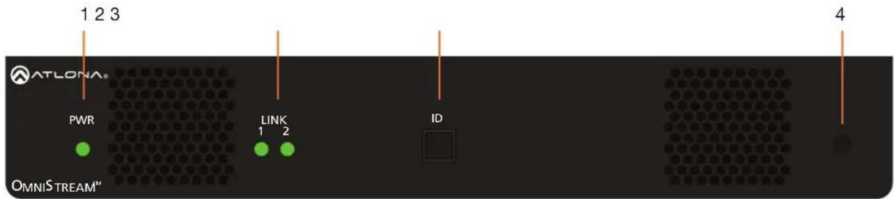
Front
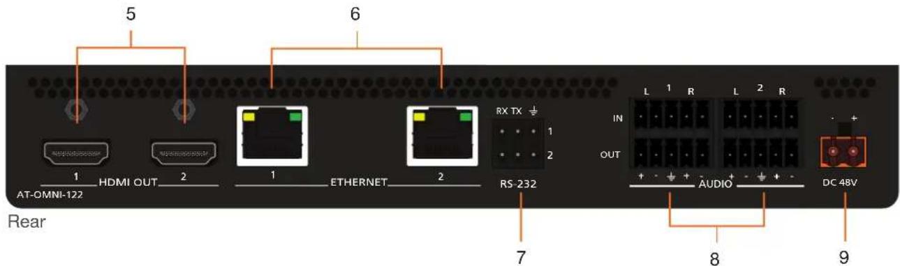
1 PWR
This LED indicator is green when the unit is powered.
2 LINK 1 / LINK 2
These LED indicators show the active input status.
3 ID
Press this button to send out a broadcast message to any network devices that are listening. This button is also used to set the encoder to factory-default settings. Refer to ID Button (page 24) for more information.
4 REBOOT
Use a pointed object to press this recessed button and reboot the unit.
5 HDMI OUT 1 / HDMI OUT 2
Connect HDMI cables from these ports to an HD display.
6 ETHERNET 1 / ETHERNET 2
Connect Ethernet cables from these ports to the Local Area Network (LAN).
RS-232
Use the included Phoenix terminal block to connect up to two RS-232 devices to this port. The RS-232 2 port also supports IR pass-through. Refer to IR Connections (page 13) for more information.
7 AUDIO 1 / AUDIO 2
Connect the included Phoenix terminal blocks to embed audio on the output stream and/or connect to an audio output device.
8 DC 48V
Connect the optional 48V DC power supply to this power receptacle. This power supply is available, separately.
Installation
RS-232 Connections
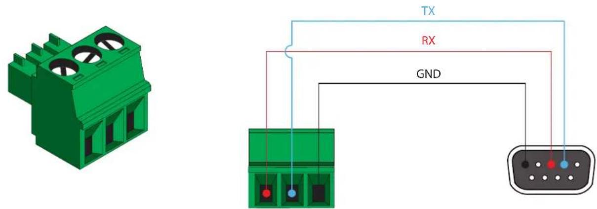
Both the AT-OMNI-121 and AT-OMNI-122 provide RS-232 over IP, allowing communication between an automation system and an RS-232 device. This step is optional. Note that different Phoenix connectors are provided with each product.
- Use wire strippers to remove a portion of the cable jacket.
-
Remove at least 3/16" (5 mm) from the insulation of the RX, TX, and GND wires.
-
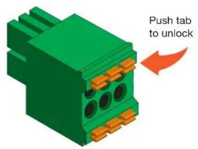
Insert the TX, RX, and GND wires into correct terminal on the included Phoenix block. If using non-tinned stranded wire, press the orange tab, above the terminal, while inserting the exposed wire. Repeat this step for the TX, RX, and GND connections.
AT-OMNI-121
AT-OMNI-122
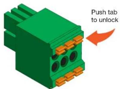
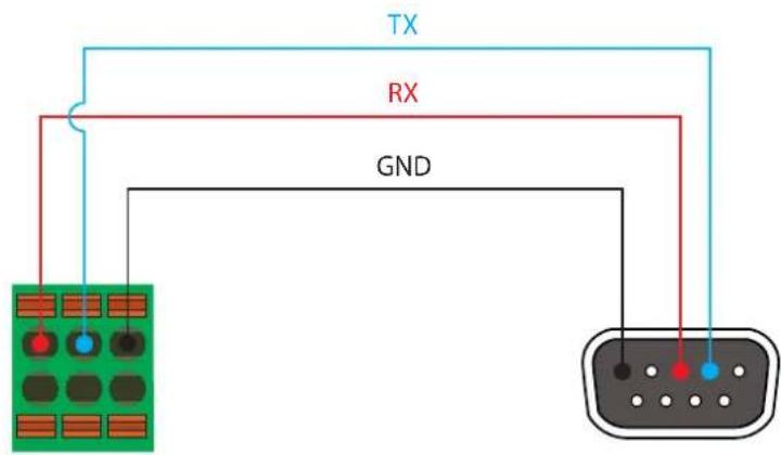

NOTE: Typical DB9 connectors use pin 2 for TX, pin 3 for RX, and pin 5 for ground. On some devices, pins 2 and 3 are reversed.
IR Connections
The same port that provides RS-232 connections also supports bidirectional IR pass-through, allowing a device to be controlled from either the headend or the decoder endpoint. This step is optional. Either the top three or bottom three set of terminals can be used for IR. Only the RS-232 2 port (bottom set of connectors) supports both RS-232 and IR. Therefore, this port must be used for IR connections.
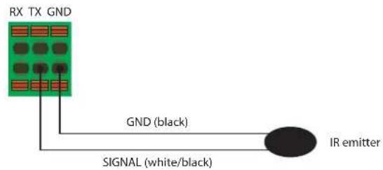
IR emitter configuration
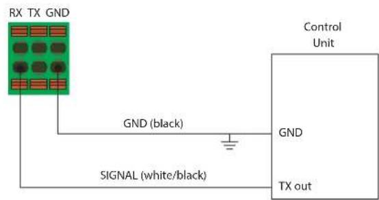
IR extender configuration
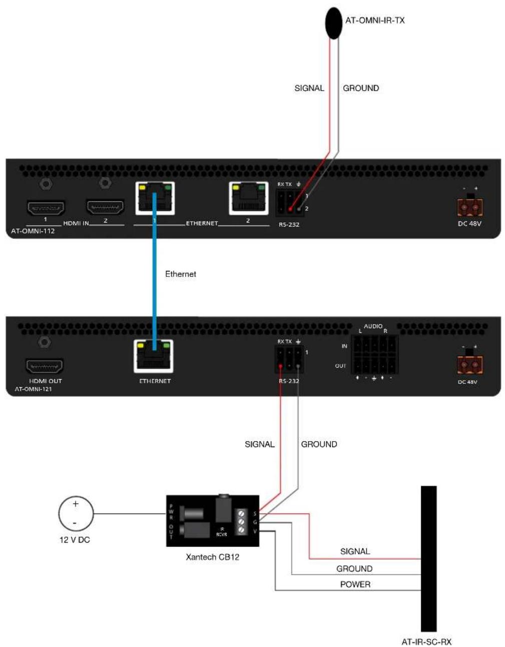
The following components are required. Note that other components may also be used. However, Atlona has tested and verified the following components for this application:
• Xantech CB12 1 Zone Connecting Block
• Xantech 12 V PSU
- Atlona AT-IR-CS-RX
• Atlona AT-OMNI-IR-TX
Decoder
- Connect the SIGNAL, GROUND, and POWER leads from the Xantech CB12 to the AT-IR-SC-RX.
- On the Xantech CB12, connect the SIGNAL and GROUND leads to the RX and ± pins, respectively, of the RS-232 2 port.
- Connect the Xantech 12 V power supply (or other compatible 12 V DC power supply) to the Xantech CB12.
Encoder
- Connect the SIGNAL and GROUND pins, from the AT-OMNI-IR-TX, to the TX and ± pins, respectively, of the RS-232 2 port.
- Refer to the illustration on the next page to verify that the correct connections have been made.
Installation
For downstream IR control, either multicast or unicast mode can be used. However, when controlling a source from the decoder (viewing location), unicast mode should be used. Refer to Unicast Mode (page 25) and Multicast Mode (page 27) for more information.

IMPORTANT: The IR emitter must be placed no more than 1" from the IR sensor on the device, in order to function properly.
Audio Connectors
In addition to passing audio directly from the encoder to the decoder, both the AT-OMNI-121 and AT-OMNI-122 provide two additional audio options. Either option can be used or they can be used simultaneously.
- HDMI audio can be de-embedded and output to two-channel analog audio.
- Two-channel analog audio can be embedded and output over HDMI.
Use the included dual five-pin Phoenix blocks. Note that each product comes with different connector blocks.
This step is optional. Refer to Configuring Audio Output (page 29) for more information.
AT-OMNI-121
- If either the AUDIO IN or AUDIO OUT port will be used, then connect the included 5-pin "captive screw" Phoenix blocks, as shown below.
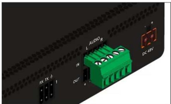
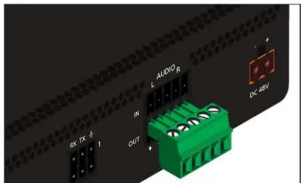
2-channel analog audio input (top) 2-channel analog audio output (bottom)
- If both AUDIO IN and AUDIO OUT terminals will be used, then connect the included 5-pin "push spring" Phoenix blocks, as shown below.
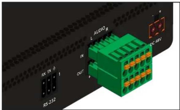
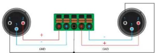
Balanced XLR audio Unbalanced XLR audio

NOTE: Unblanaced XLR audio pins require Pin 1 and Pin 3 to be connected.
AT-OMNI-122
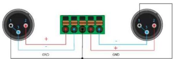
Use the top 5 pins to connect audio input sources. Use the bottom five pins to connect to audio output devices.
- Use wire strippers to remove a portion of the cable jacket.
- Locate the included Phoenix block connectors. Press the orange tab, above the terminal, while inserting the exposed wire. Release the orange tab to lock the wire in place. Balanced or unbalanced audio can be used.
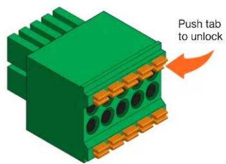
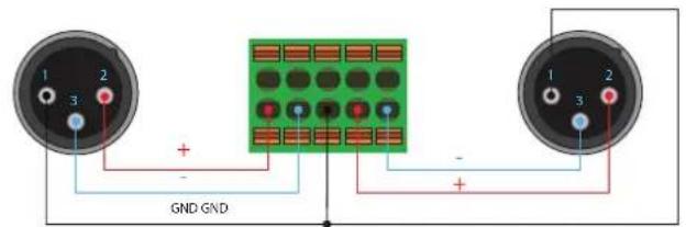
Balanced XLR audio
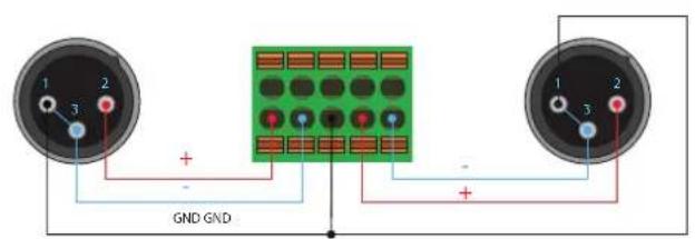
Unbalanced XLR audio

NOTE: Unblanaced XLR audio pins require Pin 1 and Pin 3 to be connected.

IMPORTANT: When using analog audio inputs on the OmniStream decoder, the decoder must be powered using the 48V power supply (AT-PS-48083-C). This power supply is sold separately and can be purchased from Atlona.
Connection Instructions
- Connect an Ethernet cable from the ETHERNET port on the decoder to a PoE-capable switch on the Local Area Network (LAN). If using the dual-channel decoder, connect a separate Ethernet cables to ETHERNET 1 and ETHERNET 2 ports.

IMPORTANT: If a PoE-capable switch is not available, then the 48V DC power supply (sold separately) must be connected to the decoder.
-
Connect an HDMI cable from the HDMI OUT port on the decoder to a display. If using the dual-channel decoder, connect an HDMI cable from each HDMI OUT port to a display.
-
RS-232 (optional)
-
Connect the RS-232 controller/automation system to the RS-232 port on the decoder.
-
Connect the RS-232 device to the RS-232 port on the decoder.
-
External Audio (optional)
-
Connect the audio inputs to the decoder, as required.
- Connect the audio outputs to the decoder, as required.

IMPORTANT: When using analog audio inputs on the OmniStream decoder, the decoder must be powered using the 48V power supply (AT-PS-48083-C). This power supply is sold separately and can be purchased from Atlona.
- IR (optional)

NOTE: For dual-channel decoders, only the RS-232 2 port supports both serial and IR. Single-channel decoders only support IR on the RS-232 2 port. The IR emitter or IR receiver must always be connected to this port. Refer to IR Configuration (page 38) for more information.
- IR emitter
Connect the IR emitter to the TX and GND pins of the RS-232 2 port. The IR emitter must be placed no more than 1" from the IR sensor on the device, in order to function properly. -
IR extender
Connect the IR extender from the RX and GND pins of the RS-232 2 port to the associated pins on the control system. -
Once power is applied, the PWR indicator, on the front panel, will turn red, then amber, then green.
Installation
Connection Diagram
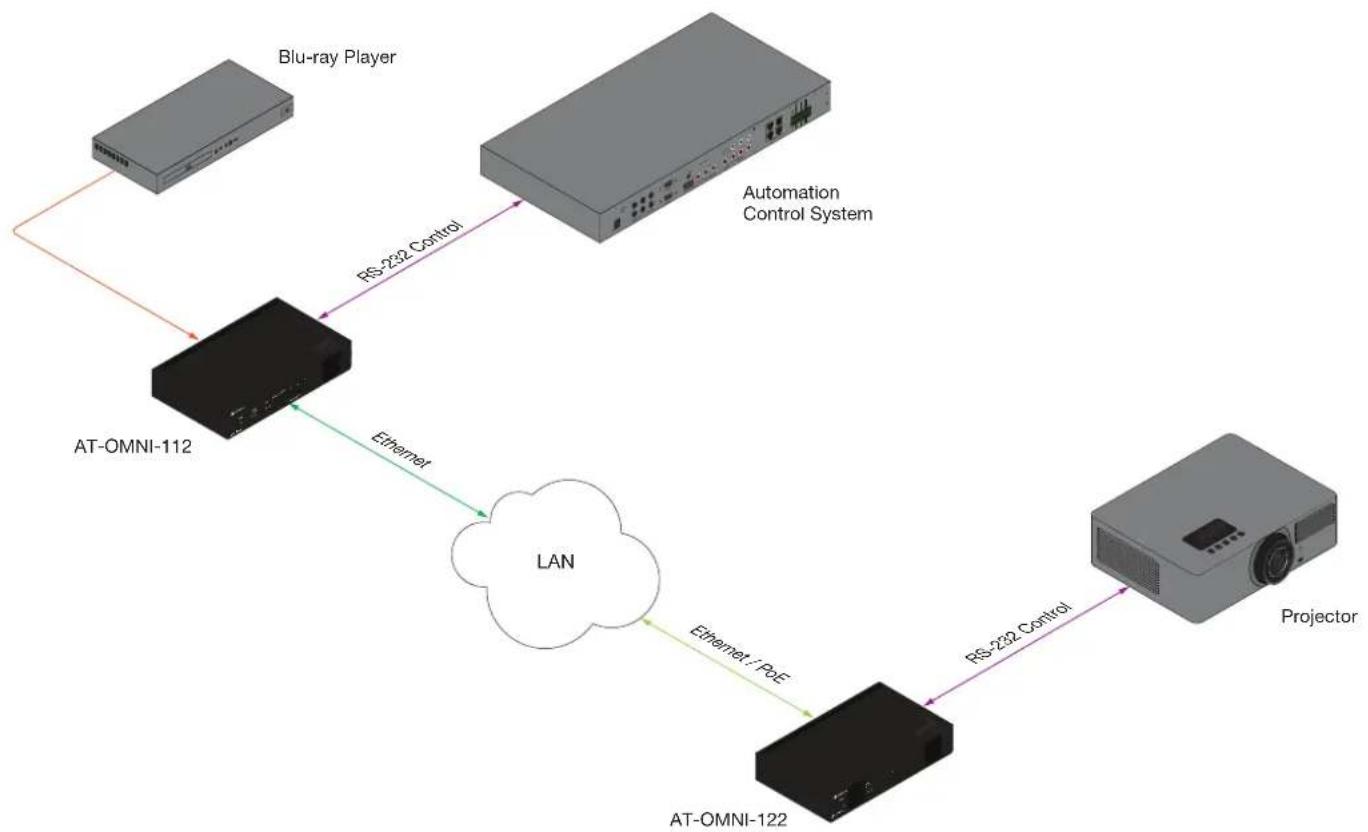
flowchart
graph TD
    A["Blu-ray Player"] -->|RS-232 Control| B["Automation Control System"]
    C["AT-OMNI-112"] -->|Ethernet| D["LAN"]
    D -->|Ethernet: P&E| E["AT-OMNI-122"]
    E -->|RS-232 Control| F["Projector"]
Configuration
Discovery using AMS
It is recommended that the Atlona Management System (AMS) be used to configure and control OmniStream devices. AMS uses multicast Domain Name Server (mDNS) to automatically configure each decoder on the network. AMS is free and can be downloaded from https://www.atlona.com/ams.
By default, the decoders are set to DHCP mode, allowing a DHCP server (if present) to assign the decoder an IP address. Once an IP address has been assigned, the Atlona Management System (AMS) can be used to manage the product on the network. Note that AMS will only be able to discover decoders if they are on the same VLAN.
Accessing Decoders in AMS
- Launch a web browser and enter the IP address of AMS, in the address bar.
- Enter the required login credentials.
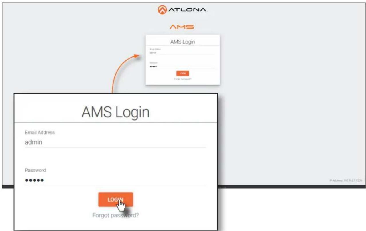
- Click the Login button.
- The AMS Dashboard will be displayed.
-
Click the ≡icon, in the upper-left corner of the AMS Dashboard.
-
Click Devices from the fly-out menu.
- Click the Unassigned option.
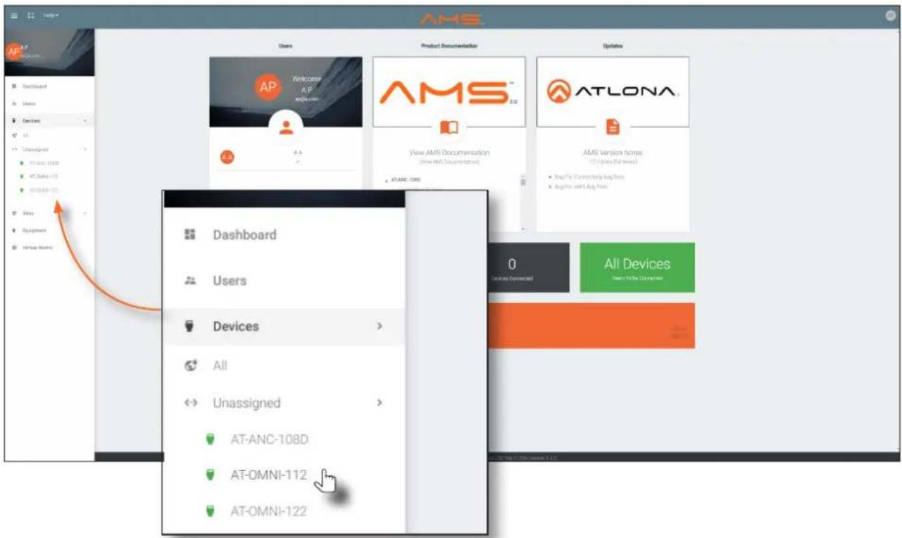
All available decoders will be displayed under the Unassigned category. When a decoder is unassigned, it means that it has not been assigned to a site, building, and/or room. Refer to the AMS User Manual for more information on these topics.
If a DHCP server is not found within 60 seconds, the decoder will be placed in Auto IP mode and assigned an IP address within the range of 169.254.xxx.xxx. If this occurs, configure the network interface of the computer that is running AMS, located on the same subnet (169.254.xxx.xxx, subnet mask 255.255.0.0). Refer to Configuring a Static IP Address (page 22) for more information on configuring an encoder in Auto IP mode.
If no OmniStream decoders are found, then verify the following:
- The computer that is running AMS must be on the same network as the OmniStream device.
-
Remove any network restrictions that may be in place. In order for mDNS to function properly, there must not be restrictions applied to the network.
-
Click the desired decoder from the Unassigned device list.
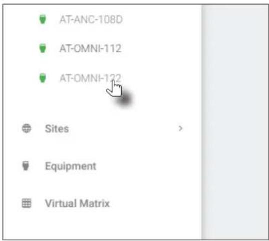
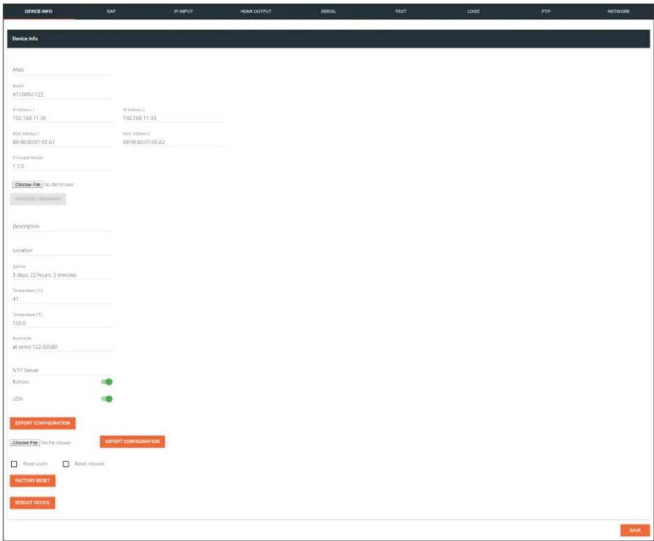
Once the unit is selected, the control interface for the encoder will be displayed. The illustration below shows the DEVICE INFO screen for an AT-OMNI-122 decoder.
Configuring a Static IP Address
The following section is only required to set the decoder, currently in Auto IP mode, to a static IP address. If a DHCP server is not found within 60 seconds, encoders are automatically placed in Auto IP mode and will be assigned an IP address within the range 169.254.xxx.xxx. If this occurs, a static IP address can be assigned to the encoder in order for AMS to locate it on the network.
- Make sure that the decoder is powered. Power will need to be supplied either by the external 48V power supply (not included) or by connecting an Ethernet cable from the decoder to a PoE-capable switch. If using the AT-OMNI-122, the Ethernet cable can be connected to either ETHERNET 1 or ETHERNET 2.
- Connect an Ethernet cable from the PC, directly to one of the Ethernet ports on the decoder. Make sure that the computer being used has AMS installed.
- Configure the PC to a static IP address that is on the same subnet as the decoder.

IMPORTANT: Before continuing, write down the current IP settings in order to restore them, later. If Obtain an IP address automatically and Obtain DNS server automatically are selected, then this step is not required.
- Login to AMS. Refer to Accessing Decoders in AMS (page 19) if necessary.
- Locate the decoder under the Unassigned section within AMS.
- Click on the device.
- Under AMS, click the NETWORK tab.
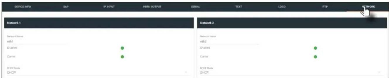
- Click the DHCP Mode drop-down list and select Static.
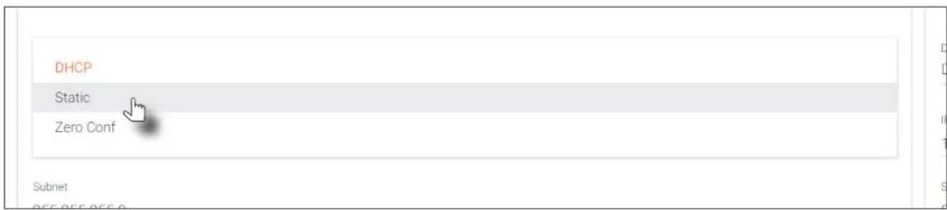
- Enter the required network information for the decoder in the IP Address, Subnet, and Gateway fields.
- Click the Save button in the bottom-right corner, to apply the changes.
- Disconnect the decoder from the PC and connect it to the network.
- The decoder is now ready for use.
Basic Operation
LED Indicators
The following table provides a listing of front-panel LED indicators and their status:
| LED Description | ||
| PWR Off • If | using a PoE switch, make | sure that the port on the switch that is connected to the encoder, has PoE enabled. When the encoder is powered using PoE, the PWR indicator will be green.Check the Ethernet cable for possible damage or loose connections.Connect the optional 48V DC power supply (available from atlona.com) to the encoder. When using an external power supply, the PWR indicator will be red. |
| Red • The decoder is booting. | ||
| Green • The decoder is ready. | ||
| LINK 1 / 2 Red | • The optional 48V DC power supply is connected, but no Ethernet cables are connected between the switch and the ETHERNET port(s).Check the Ethernet cable for possible damage or loose connections. | |
| Green • Link integrity is good between the encoder and the network. | ||
Rebooting OmniStream
To reboot the OmniStream decoder, press and release the recessed button, on the far-right side of the unit, using a small, pointed object. Rebooting the decoder does not reset the decoder to factory-default settings.

ID Button
This feature is not available on the single-channel OmniStream decoder (AT-OMNI-121).
The ID button serves two functions:
- Sends a broadcast message, over the network, to any devices that may be listening.
- Resets the encoder to factory-default settings.

Broadcast Messaging
Press and release the ID button to send a broadcast notification over the network to any devices that may be listening.
Reset to Factory-Default Settings.
- Press and hold the ID button for approximately 30 seconds.
- The LED indicators on the front panel will flash, then turn "off."
- The encoder is now reset and will need to be reconfigured.

WARNING: Performing a factory-default reset will erase all user-programmed settings from the encoder. IP settings are not preserved.
Unicast Mode
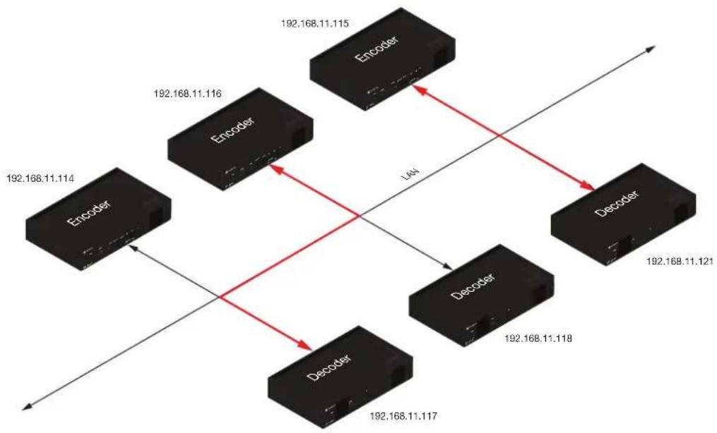
The term unicast is used to describe a configuration where information is sent from an encoder to a single decoder. Although it is common to have multiple encoder and decoder units within a system, it may also be desirable to restrict a single encoder to communicate with one decoder. In unicast mode, OmniStream encoders and decoders function similar to an n x 1 switcher. Changing the destination IP address at the encoder, will direct the stream to be received by a different decoder.
The illustration below shows three encoders and three decoders on a network, operating in unicast mode. The red lines indicate the data paths from each encoder to a separate (single) decoder.

NOTE: By default, both encoders and decoders are shipped in multicast mode.
- Login to AMS. Refer to Accessing Decoders in AMS (page 19) if necessary.
- Go to the encoder AMS interface. Refer to the OmniStream Single-Channel / Dual Channel A/V Encoder User Manual, if necessary.
- Click SESSION in the menu bar and scroll down to the Video section.
- Enter the IP address of the decoder in the Destination IP Address field. If using dual-channel encoders, repeat this process for each session.
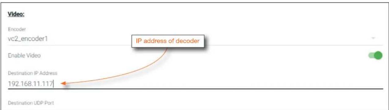
Basic Operation
- Go to the decoder AMS interface.
- Click IP INPUT from the menu.
- Remove the IP address from the Multicast Address field.
- Click the SAVE button to commit changes.
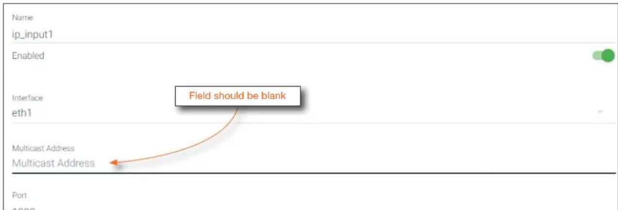
- Unicast setup is complete. The decoder unit will now receive streams exclusively from the encoder containing the IP address of this decoder.
Multicast Mode
The term multicast is used to describe a configuration where information is sent from one or more points to a set of other points. For example, a single encoder can transmit data to multiple decoders. In addition, if multiple encoders are used, each encoder can stream data to any decoder that is not already receiving data from an encoder. In multicast mode, OmniStream encoders and decoders function similar to a matrix switcher.
The illustration below shows three encoders and three decoders on a network, operating in multicast mode, where multiple decoders are subscribed to a single encoder. The red lines indicate the data paths from an encoder (192.168.11.117) to multiple decoders.

NOTE: By default, both encoders and decoders are shipped in multicast mode.
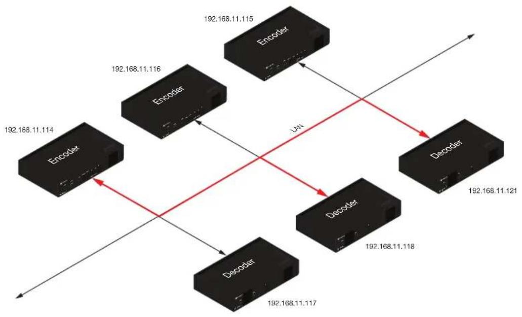
- Login to AMS. Refer to Accessing Decoders in AMS (page 19) if necessary.
- The AMS Dashboard will be displayed.
- Click the ≡icon, in the upper-left corner of the AMS Dashboard.
- Click Virtual Matrix from the fly-out menu. Refer to The Virtual Matrix (page 85), if necessary.
- Locate the desired encoder in the Virtual Matrix, as shown on the next page.
- Create a cross-connection to the desired decoder. When a cross-connection is created, AMS will automatically assign a multicast IP address to both the encoder and decoder. By default, AMS automatically assigns a multicast IP address to each OmniStream encoder and decoder.
Refer to the illustration on the following page, if necessary.
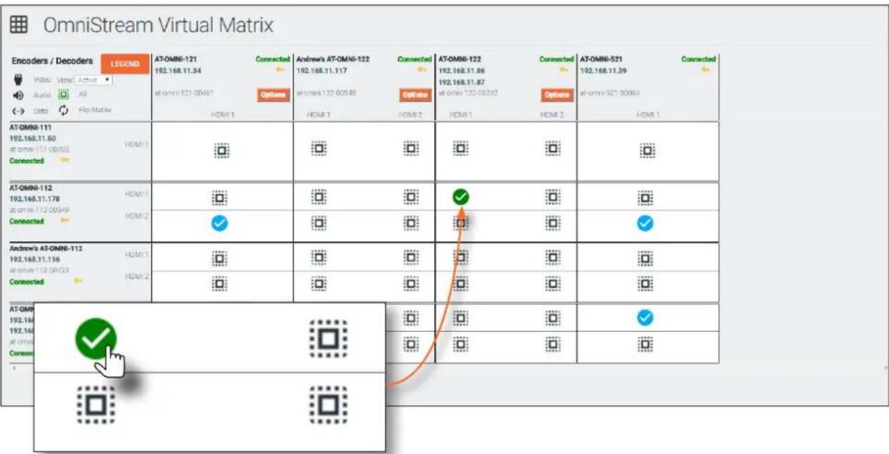
Configuring Audio Output
In addition to passing audio directly from the encoder to the decoder, both the AT-OMNI-121 and AT-OMNI-122 provide two additional audio options
- HDMI audio can be de-embedded and output to two-channel analog audio.
- Two-channel analog audio can be embedded and output over HDMI.
This section covers both methods. If using a single-channel decoder, only a single AUDIO IN and AUDIO OUT port will be available.

IMPORTANT: When using analog audio inputs on the OmniStream decoder, the decoder must be powered using the 48V power supply (AT-PS-48083-C). This power supply is sold separately and can be purchased from Atlona.
De-embedding Audio
De-embedding audio will extract the HDMI audio and automatically downmix to two-channel analog audio, using the included captive-screw connectors.
- Connect the power supply to the DC 48V connector on the decoder.
- Connect the included 5-pin captive screw connectors to the AUDIO OUT ports. Refer to Audio Connectors (page 15) for wiring information.
- Login to AMS. Refer to Accessing Decoders in AMS (page 19) if necessary.
- Select the decoder in AMS.
- Click HDMI OUTPUT in the menu bar.
- Scroll down to the Audio section.
- Click the Analog Output toggle switch to enable it. When enabled, the toggle switch will be green. Also note that the Analog Output Power indicator, above the toggle switch, will be green. This indicates that the external power supply is connected to the decoder.
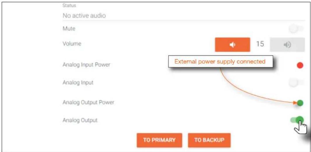
- Audio from the source will now be heard on the ANALOG OUT port of the decoder. Note that when audio is de-embedded, it will not longer be audible using the HDMI OUT port on the decoder.
Embedding Audio
Embedding audio will replace the existing HDMI audio source, normally heard on the output of the decoder. The analog audio will be heard on the HDMI OUT port of the decoder.
- Connect the power supply to the DC 48V connector on the decoder.
- Connect the audio source to the AUDIO IN ports, using the included 5-pin captive screw connectors. Refer to Audio Connectors (page 15) for wiring information.
- Login to AMS. Refer to Accessing Decoders in AMS (page 19) if necessary.
- Select the decoder in AMS.
- Click HDMI OUTPUT in the menu bar.
- Scroll down to the Audio section.
- Click the Analog Input toggle switch to enable it. When enabled, the toggle switch will be green. Also note that the Analog Input Power indicator, above the toggle switch, will be green. This indicates that the external power supply is connected to the decoder.
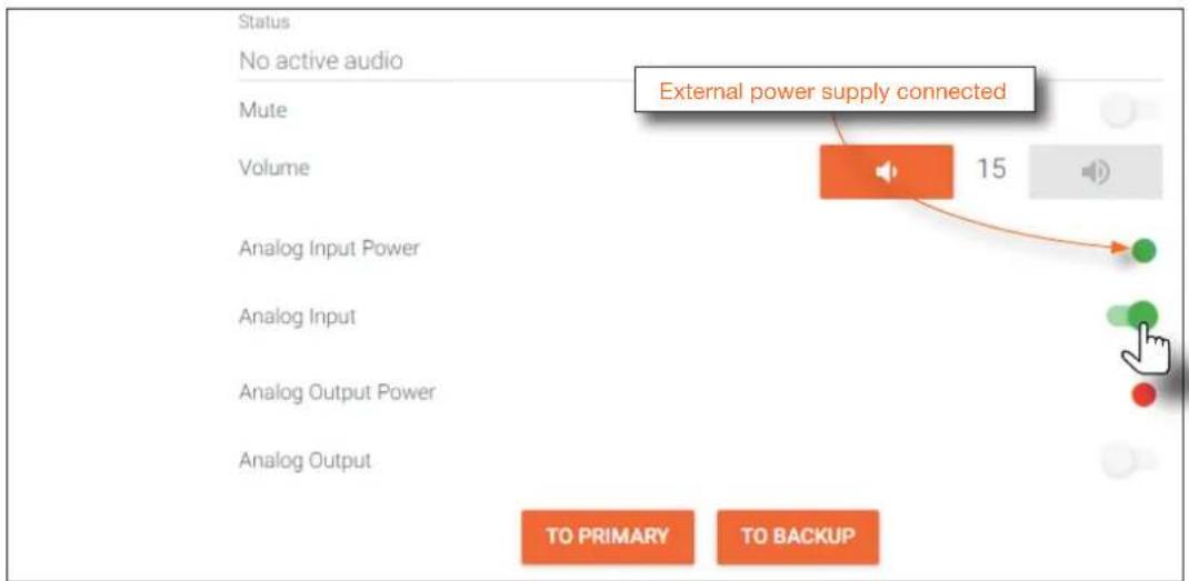
- Audio from the source will now be heard on the HDMI OUT ports on the decoder.
Control Using RS-232 Commands
RS-232 data can be sent over IP using one of two methods:
- Triggering stored commands, directly from the decoder unit.
• Using the TCP proxy feature.
Both methods will be discussed in this section.

NOTE: When configuring RS-232, always make sure to configure the correct baud rate, data bits, parity bit, stop bits, and flow control settings, as required by the connected device. These settings can be changed in the Serial Port section, under the SERIAL menu.
Triggering Stored Commands
This method will trigger commands directly from the serial port on the decoder to the sink device. The decoder provides the following commands: Display Off, Display On, Volume Up, and Volume Down.
- Login to AMS. Refer to Accessing Decoders in AMS (page 19) if necessary.
- Select the decoder in AMS.
- Click SERIAL in the menu bar.
- Configure the proper serial port settings under the Serial Port section for the connected device, then click the SAVE button.
- Scroll down to the Serial Configuration section.
- Click the Port drop-down list and select the desired serial port.
- Click the Mode drop-down list and select the Output option, then click the SAVE button.
- Scroll down to the Command sections. Each section is labeled for the command type.
- Click the Mode drop-down list and select the Decoder option.
- Enter the associated command in the ASCII or HEX fields, then click the SAVE button. Refer to the User Manual for the sink device for the list of available commands.
- Repeat steps 8 - 10 for each command, as desired. Trigger the desired command by executing the TrigRS232 command. Refer to the OmniStream Application Programming Interface for more information.
Using TCP Proxy
This method can be used, for example, to send a command to a projector that is connected using an Ethernet cable. In this way, the serial command can be sent to the projector over IP.
- Follow steps 1 - 6, above, for Triggering Stored Commands.
- Click the Mode drop-down list and select the tcpproxy option, then click the SAVE button.
- Click the Interface drop-down list to select the interface (Ethernet port) that will be used to transmit the data.
- Click the Mode drop-down list and select the Decoder option.
- Enter the port number in the Port field. This number can be in the range from 0 to 65535.
- Click the SAVE button to commit all changes.
802.1X Authentication
802.1X is a server-based port authentication which restricts unauthorized (rogue) clients from connecting to a Local Area Network through a public port. In its simplest form, 802.1X usually involves three parties: supplicant (client device), authenticator (Ethernet switch or WAP), and an authentication server. Before the device is permitted on the network, port communication is restricted to Extensible Authentication Protocol over LAN (EAPOL) traffic. If the device passes the authentication process, the authentication server notifies the switch, allowing the client to access the LAN. The illustration below shows the basic architecture.

NOTE: As of this writing, AMS does not currently support 802.1X configuration. This will be added in a future release of AMS. Contact Atlona for more information. Use the following instructions to set up video mode using the OmniStream web GUI.

WARNING: Connecting an 802.1X-enabled decoder to a network without an active or operational authentication server, will result in an encoder that does not function until the expected message is returned from a RADIUS server. If it is unclear as to whether the network uses 802.1X authentication, consult the IT administrator for assistance.
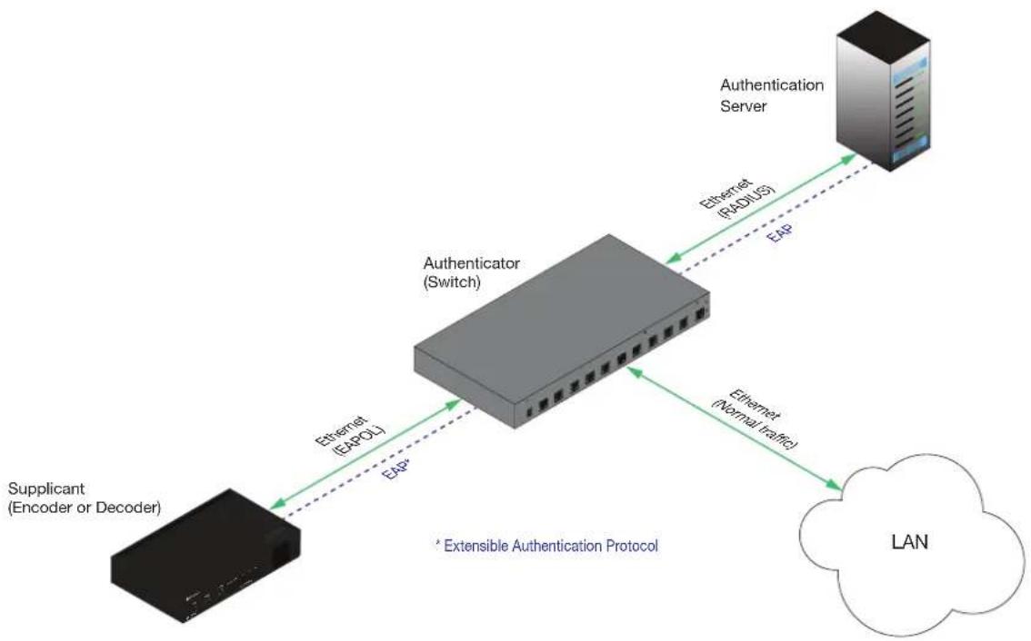
flowchart
graph LR
    A["Supplicant (Encoder or Decoder)"] -->|Ethernet (EAPD)| B["Authenticator (Switch)"]
    B -->|Ethernet (PADIUS)| C["Authentication Server"]
    C -->|EAP| B
    B -->|Ethernet (Normal traffic)| D["LAN"]
    style A fill:#000,stroke:#333
    style B fill:#999,stroke:#333
    style C fill:#ccc,stroke:#333
    style D fill:#fff,stroke:#333
Three options are available on both the OmniStream encoder and decoder.
| Protocol Description | |
| none 802.1X protocol disabled | |
| PEAP/MSCHAPv2 Protected EAP; requires basic credentials in addition to a CA (certificate authority) certificate. | |
| EAP-TLS EAP Transport Layer Security; requires a client certificate, client private key, and CA (certificate authority) certificate. |
EAP-TLS Protocol
- Launch a web browser.
- Enter the IP address of the OmniStream decoder in the address bar of the web browser.
- Enter the username and password at the login screen. The default login credentials are as follows. Note that login credentials are case-sensitive.
Username: admin
Password: Atlona
- Click the Continue button, or press the ENTER key, to continue.
- Click Network in the menu bar, near the top of the page.
- Click the 802.1x Mode drop-down list and select EAP-TLS.
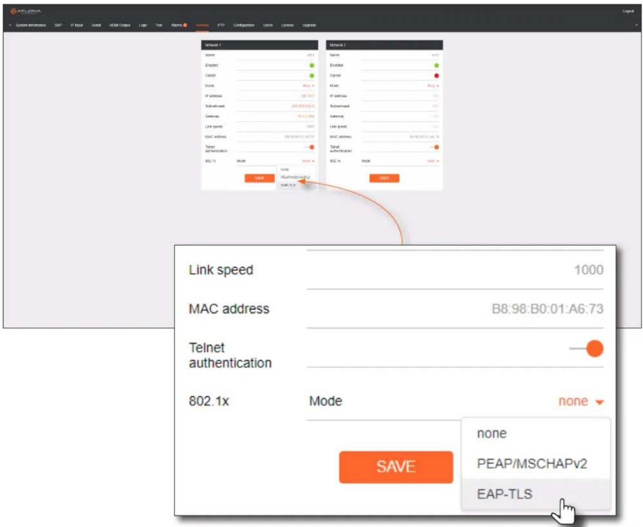
- Three additional fields will be displayed: Client certificate, Client private key, and CA certificate. Provide the required information in each field.
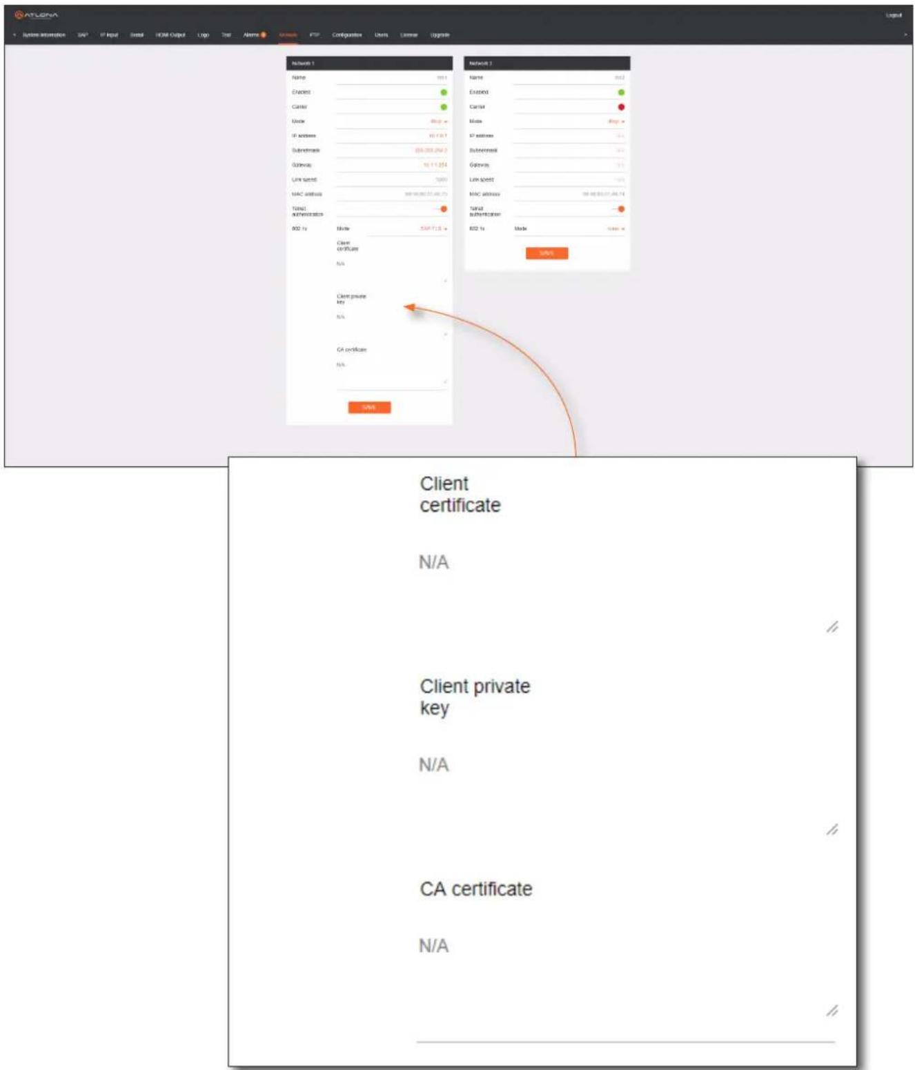
- Click the SAVE button near the bottom of the page. If using dual-channel decoders, both Network 1 and Network 2 (both Ethernet ports) will need to be set up, depending upon the system requirements.
PEAP/MSCHAPv2 Protocol
- Launch a web browser.
- Enter the IP address of the OmniStream ddecoder in the address bar of the web browser.
- Enter the username and password at the login screen. The default login credentials are as follows. Note that login credentials are case-sensitive.
Username: admin
Password: Atlona
-
Click the Continue button, or press the ENTER key, to continue.
-
Click Network in the menu bar, near the top of the page.
-
Click the 802.1x Mode drop-down list and select PEAP/MSCHAPv2.
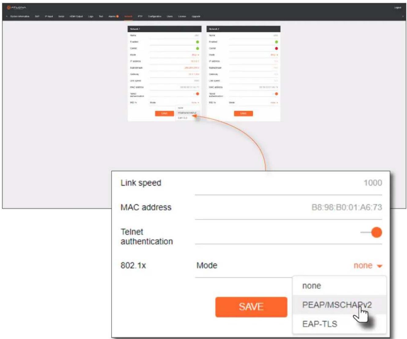
- Three additional fields will be displayed: Identity, Password, and CA certificate. Provide the required information in each field.
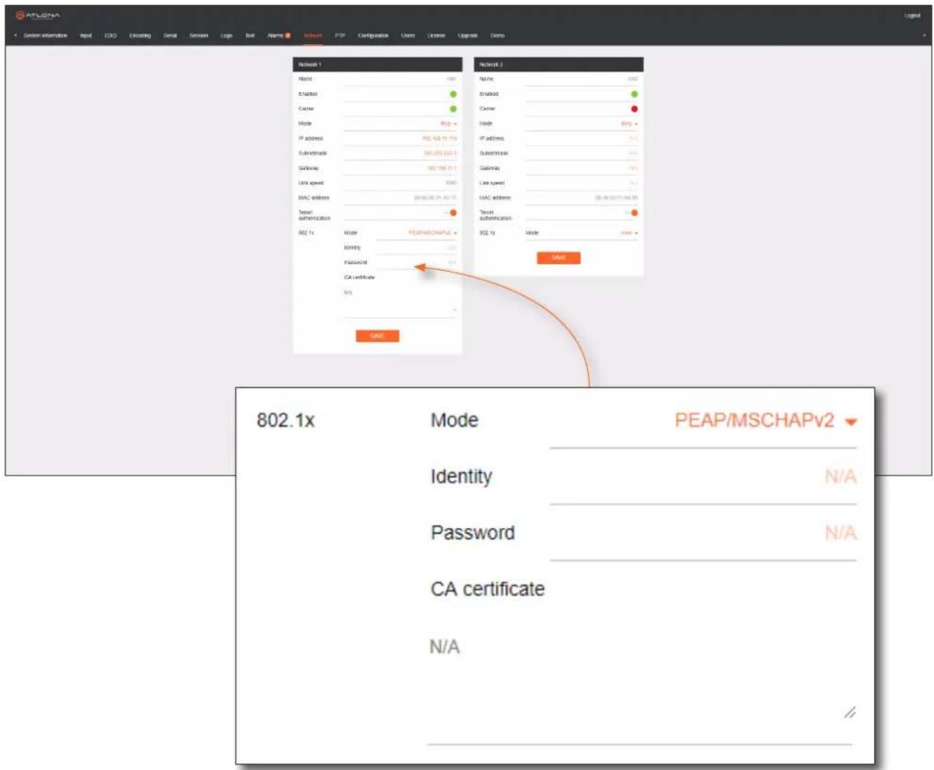
- Click the SAVE button near the bottom of the page. If using dual-channel decoders, both Network 1 and Network 2 (both Ethernet ports) will need to be set up for, depending upon the system requirements.
AES67 Audio
AES67 audio is a standard for high-performance audio streaming over IP, providing several features such as synchronization, media clock identification, and connection management. AES67 does not support compressed audio formats, such as Dolby® Digital, and others. Source audio must be transmitted as LPCM 2.0 or 5.1.

NOTE: As of this writing, AMS does not currently support AES67 configuration. This will be added in a future release of AMS. Contact Atlona for more information. Use the following instructions to set up video mode using the OmniStream web GUI.
- Launch a web browser.
- Enter the IP address of the OmniStream decoder in the address bar of the web browser.
- Enter the username and password at the login screen. The default login credentials are as follows. Note that login credentials are case-sensitive.
Username: admin
Password: Ationa
- Click the Continue button, or press the ENTER key, to continue.
- Go to the encoder interface and click Session in the menu bar. Refer to the OmniStream Single-Channel / Dual Channel A/V Encoder User Manual, if necessary.
- Scroll down to the Audio section and click the Enable AES67 toggle switch to enable or disable this feature. When enabled, the toggle switch will be orange.
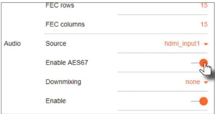
- Click the SAVE button within the Session section.
- Select the type of downmixing from the Downmixing drop-down list, if desired.
- Go to the decoder interface and click SAP from the menu bar, at the top of the screen. Under the SAP section, click the Enable toggle switch and enable SAP. When enabled, the toggle switch will be orange. If the decoder is to receive AES67 audio, this step is required.
- Click the SAVE button in the SAP section.
IR Configuration

NOTE: For dual-channel decoders, only the RS-232 2 port supports both serial and IR. Single-channel decoders only support IR on the RS-232 2 port. The IR emitter or IR receiver must be connected to this port. Refer to IR Connections (page 13) for wiring information.
- Login to AMS. Refer to Accessing Decoders in AMS (page 19), if necessary.
- The AMS Dashboard will be displayed.
- Click the ≡icon, in the upper-left corner of the AMS Dashboard.
- Locate the desired decoder from the AMS Device List, then click SERIAL in the menu bar.
- Under the Serial Port 2 section, click the Mode drop-down list and select infrared. Note that for single-channel decoders, infrared will be the only option for Serial Port 2.
Serial Port 2
Name
serial_port2
Supported Modes
infrared, serial
infrared
serial

9600
Data Bit
8
Parity
None
Stop
1
Flow Control
None
SAVE
Basic Operation
- Click the SAVE button, in the Serial Port 2 section to commit changes.
- Scroll down and locate the Serial Configuration 2 section.
- Click the Interface drop-down list and select the desired interface.
- Enter the IP address, in the Destination IP Address field, where the IR data will be sent.
- Enter the port number in the Destination UDP Port field.
- Click the Enabled toggle switch to enable the serial port. When enabled, the toggle switch will be green.
- Click the SAVE button to commit changes.
Serial Configuration 2
Name
serial_use2
Port
serial_port2
Mode
Output
Bidirectional:
Interface
eth1
Destination IP Address
10.1.0.3
Destination UDP Port
5004
Enabled


Scrambling
OmniStream supports 128-bit Advanced Encryption Standard (AES) scrambling for both audio and video streams. Scrambling can be enabled or disabled through AMS, and can be individually applied to video, audio, or both. Scrambling can be enabled either before or after the decoding process is started. Data streams cannot be scrambled; only video and audio can be scrambled. When scrambled information is received from an encoder, it will need to be descrambled before it can be displayed.
When scrambling is enabled, the scrambling key can be found under the HDMI OUTPUT page on the decoder.
Standard Method
- Click HDMI OUTPUT in the menu bar.
- Under the desired Session, click the Enabled toggle switch, next to Descrambling, to enable it. Once enabled, the toggle switch will be green and the Key field will be displayed.
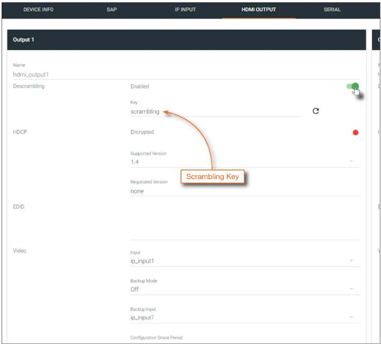
- Enter the desired scrambling key in the Key field.

NOTE: If a user-defined key is specified, then it must be a minimum of eight alphanumeric characters. Special characters and spaces are not permitted.
- Click the Save button at the bottom of the page to commit the changes.
Using the Virtual Matrix
- Access the Virtual Matrix. Refer to The Virtual Matrix (page 85) for more information.
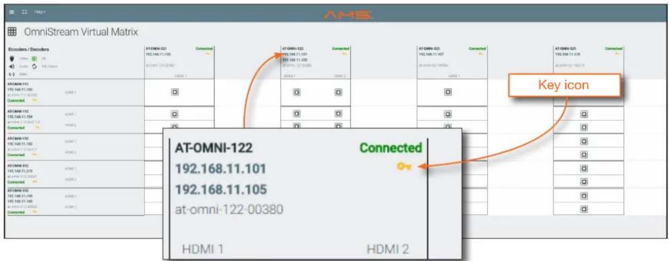
- Locate the desired encoder or decoder. Scrambling is handled on the encoder; descrambling is handled on the decoder.
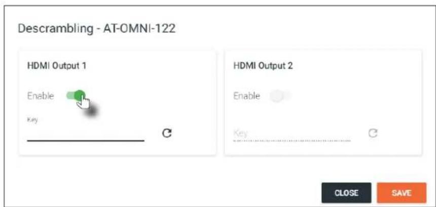
- Click the yellow key icon. The Scrambling dialog box will be displayed. If the key icon for a decoder is clicked, then the Descrambling dialog box will be displayed.
- Click the Enable toggle switch to enable scrambling for the desired session.
- Enter the desired scrambling key using one of the following methods:
- Manual enter a user-defined key in the Key field.
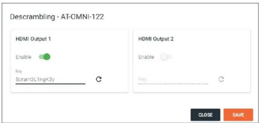
- Click the C icon to generate a random key using AMS. Each time this icon is clicked, a new scrambling key will be generated.
- Repeat the above process for each session.
- Click the Save button to commit the changes.
Setting the Video Mode
OmniStream offers two video modes: Video and PC application. These two modes will optimize the image, based on the type of information that is being displayed. Use the Video mode when display motion graphics/video. Set this mode to PC application when viewing static images, such as spreadsheets or similar content.
- Login to AMS. Refer to Accessing Decoders in AMS (page 19), if necessary.
- Click the HDMI OUTPUT in the menu bar.
- Scroll down to the Video Optimization section and click the Video Optimization drop-down list to select the desired mode.
| Mode Description | |
| Computer Graphics Optimizes the image | when viewing static images, such as spreadsheets or similar content. |
| Motion Video Provides the best viewing | experience when streaming motion graphics and/or video. |
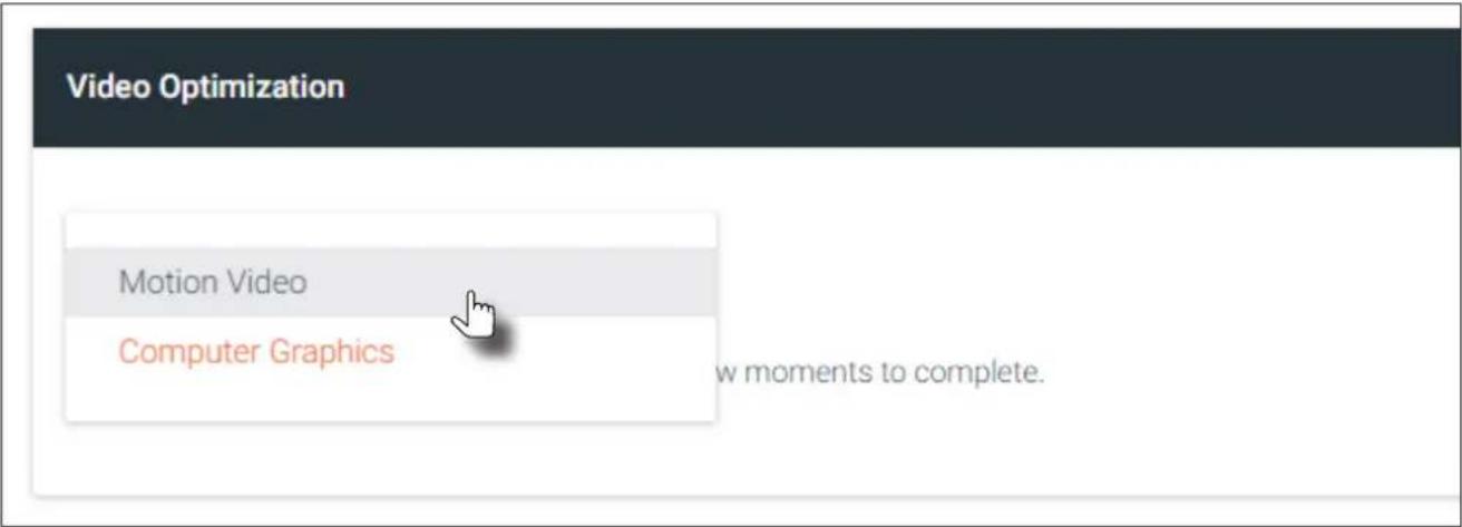
- Click the SAVE button, within the Video Optimization section to commit changes. Note that switching between video modes may take a few moments to complete.
- Go to the encoder interface and repeat the process. Refer to the OmniStream Single-Channel / Dual Channel A/V Encoder User Manual, if necessary.

NOTE: In order to use 3840x2160p60 signals, the System mode must be set to Video.
Slate / Logo Insertion
Slate / logo insertion is managed from within AMS. The difference between a “slate” and “logo” is in the size of the image and how it is used: Logos are classified as smaller, low-resolution images that can be positioned at specified locations on the screen. Slates occupy the entire screen. Note that while logos may be used as slates, the image quality will be degraded, as the image will be scaled to fill the screen.
Slate / logo insertion can be performed on both the encoder and decoder. When configured on the encoder, the image that is displayed on the output (decoder) will be from the encoder IP address(es) to which each decoder is subscribed. When configuring on the decoder, the presence of the image is specified on the (individual) HDMI output. Refer to the OmniStream Single-Channel / Dual Channel A/V Encoder User Manual, for information on managing slate / logo insertion on encoder units.

NOTE: When using 4K images, the image width must not exceed 30% of the horizontal resolution.
- Login to AMS. Refer to Accessing Decoders in AMS (page 19) if necessary.
- Click the LOGO tab in the menu bar.
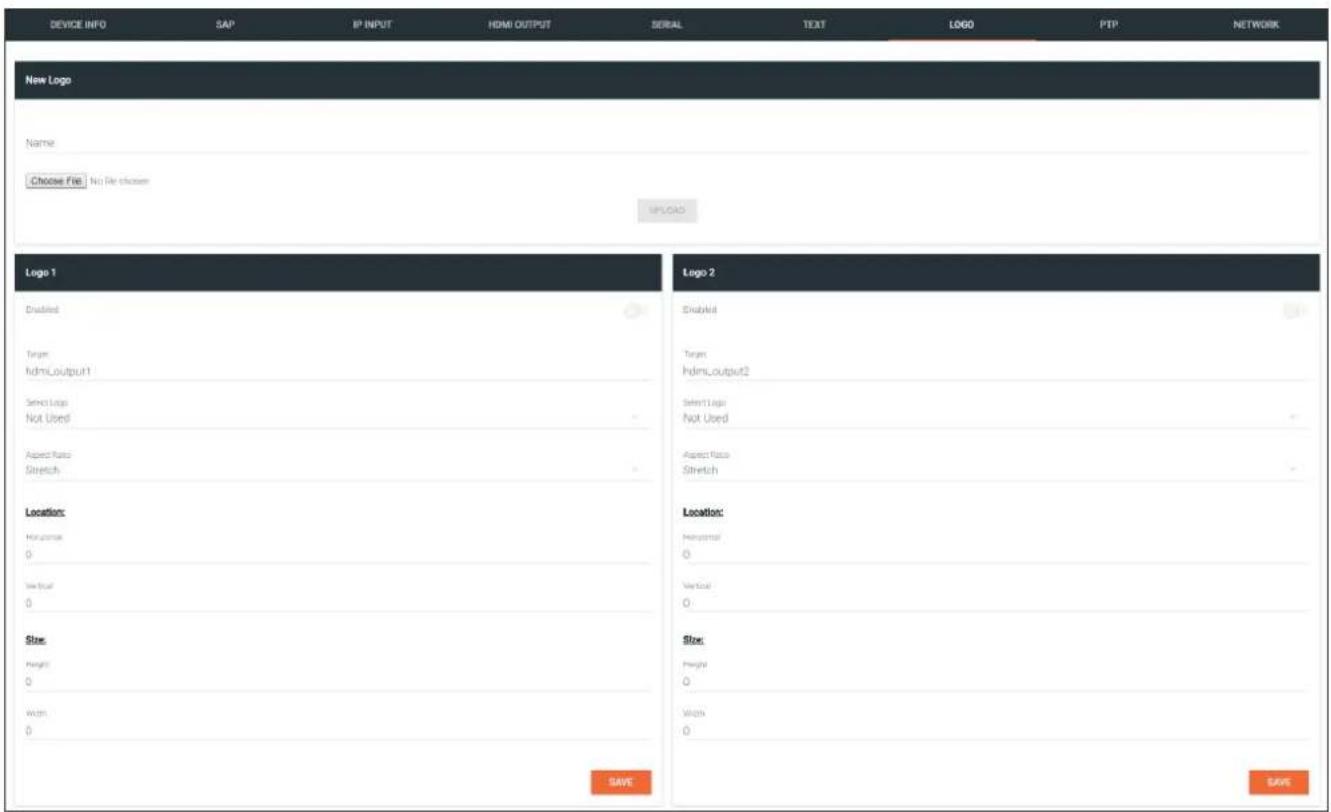
- Under New logo, click the Choose File button and select the image to be used. Note that only .png files are valid selections.
- Enter the name of the image in the Name field. If a name is not specified, then the UPLOAD button will be disabled.
- Click the UPLOAD button to upload the file.
- A new logo box will be added with the name of the logo that was provided in Step 4.

NOTE: If the selected image will be used as a logo, then proceed with Steps 7 through 9. If the image will be used as a slate, skip to Step 10.
- Click the logo from the Select Logo drop-down list. To prevent the image from being displayed, select the Not used option.
- Click the Aspect Ratio drop-down list to set the aspect ratio of the image. Selecting Keep will maintain the aspect ratio of the logo source file. Selecting Stretch will force the logo to adhere to the user configured settings for the logo size.
- Set the location of the image by entering the desired values in the Horizontal and Vertical fields.
-
Define the size of the image by entering the desired values in the Height and Width fields.
-
Click the HDMI OUTPUT tab.
-
Click the Slate mode drop-down list, and select Off, Manual, or Auto.
- Off
Disables the image from being displayed.
- Manual
The image will always be displayed, superimposed on the source signal, and will remain even if the source signal is lost.
- Auto
The image will only be displayed when the source signal is lost. For example, this mode is useful in conference room applications for displaying system instructions when no sources are connected.
-
Click the Slate Logo drop-down list and select the desired logo. Note that if Slate Mode is set to Off, then this field will not be visible.
-
Click the SAVE button to apply all changes.
Deleting Slates / Logos
Follow the instructions below to remove a logo from the Logo tab.
- Click the LOGO tab in the menu bar.
- Click the DELETE button for the desired logo box. If the DELETE button is disabled, do the following:
a. Scroll down to the Logo Insertion boxes.
b. Click the Select Logo drop-down list and select Not Used.
c. Click the SAVE button.
d. Refresh the page.
e. Click the DELETE button to remove the logo.
Text Insertion

NOTE: Text Insertion is only supported when the frame rate conversion is set to sub-frame latency mode. To set the frame rate conversion mode, go to the HDMI Output menu and select Sub Frame Latency from the Frame Rate Conversion drop-down list.
- Login to AMS. Refer to Refer to Accessing Decoders in AMS (page 19) if necessary.
- Click TEXT in the menu bar.
| DEVICE INFO | SAP | IP INPUT | HDMI OUTPUT | SERIAL | TEXT | LOGO | PTP | NETWORK |
| Text 1 | Text 2 | |||||||
| Text Name text_insertion1 | Text Name text_insertion2 | |||||||
| Enabled | Enabled | |||||||
| Text | Text | |||||||
| Scroll Speed 0 | Scroll speed 0 | |||||||
| Dimensions 0 | Dimensions 0 | |||||||
| Color: Color white - | Color: Color white - | |||||||
| Size 255 | Size 255 | |||||||
| Diameter 255 | Diameter 255 | |||||||
| Size 255 | Size 255 | |||||||
| Airline 255 | Airline 255 | |||||||
| Location: Horizontal (%) 0 Vertical (%) 0 Size Width (%) 0 Height (%) 0 Location: Horizontal (%) 0 Vertical (%) 0 Size Width (%) 0 Height (%) 0 | ||||||||
- Click the Enable toggle switch, to allow the text to be displayed.
- In the Text field, enter the desired text.
- Specify the speed of the scrolling text in the Scroll Speed field. Values from -255 to 255 are valid. Negative numbers will scroll the text from left to right. Positive numbers will scroll text from right to left.
- Enter the number of iterations in the Iteration field. Set this field to 0 (zero) to set the number of iterations to infinity.
- Click the Color drop-down list to select the color of the text. The Red, Green, and Blue fields can be changed to further modify the color of the text. Adjust the Alpha field to control the transparency of the text. A value of 255 is opaque and a value of 0 is transparent. Numbers from 0 to 255 are valid for each of these fields.
- Specify the location of the text in the Horizontal (%) and Vertical (%) fields. Each of these values is based on the horizontal and vertical resolution of the screen.
Basic Operation
- Specify the size of the text in the Width (%) and Height (%) fields. Each of these values is based on the horizontal and vertical resolution of the screen.
- Click the SAVE button to apply all changes.
Creating Video Walls
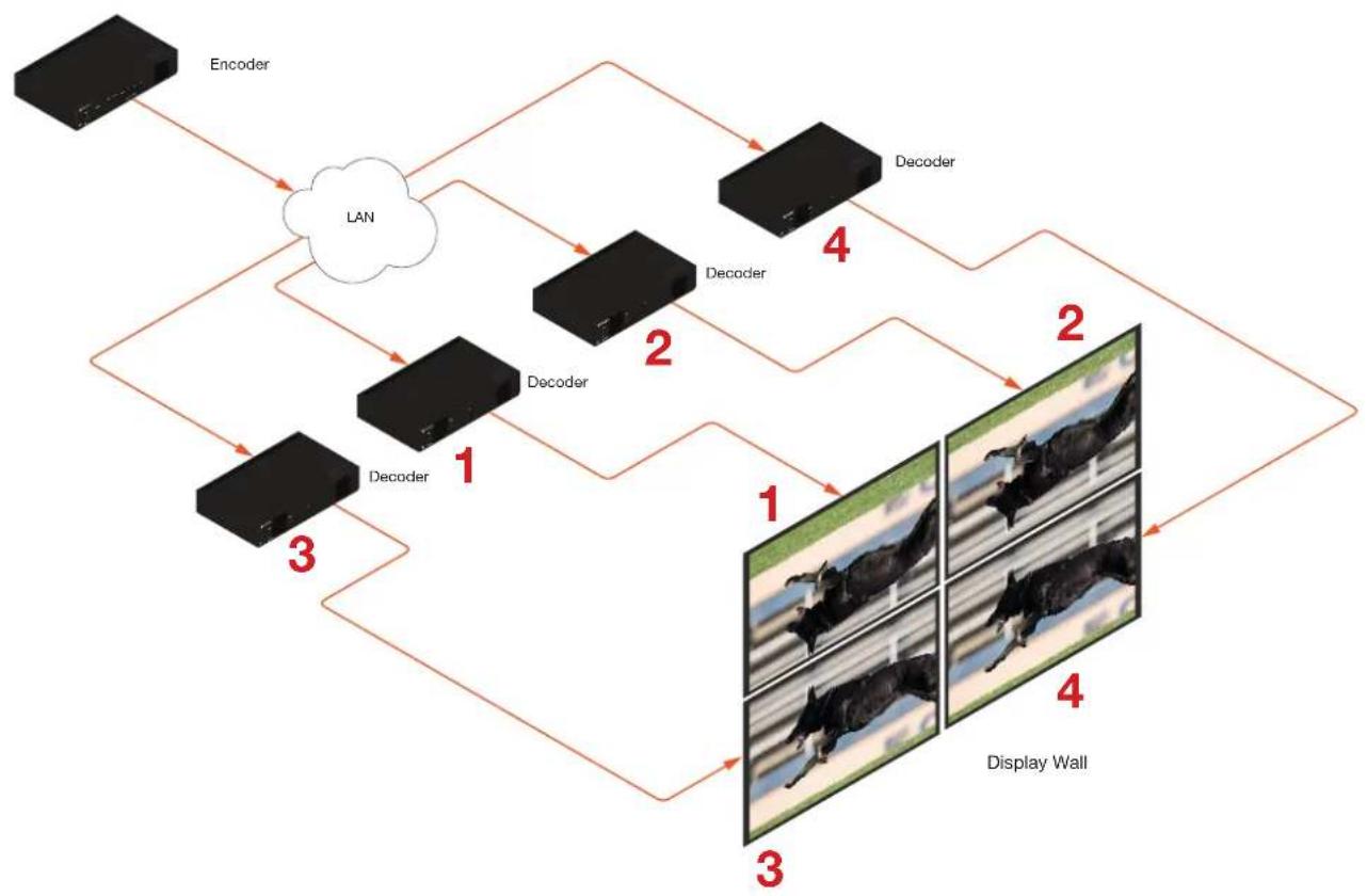
The following example illustrates how to configure a 2x2 video wall.
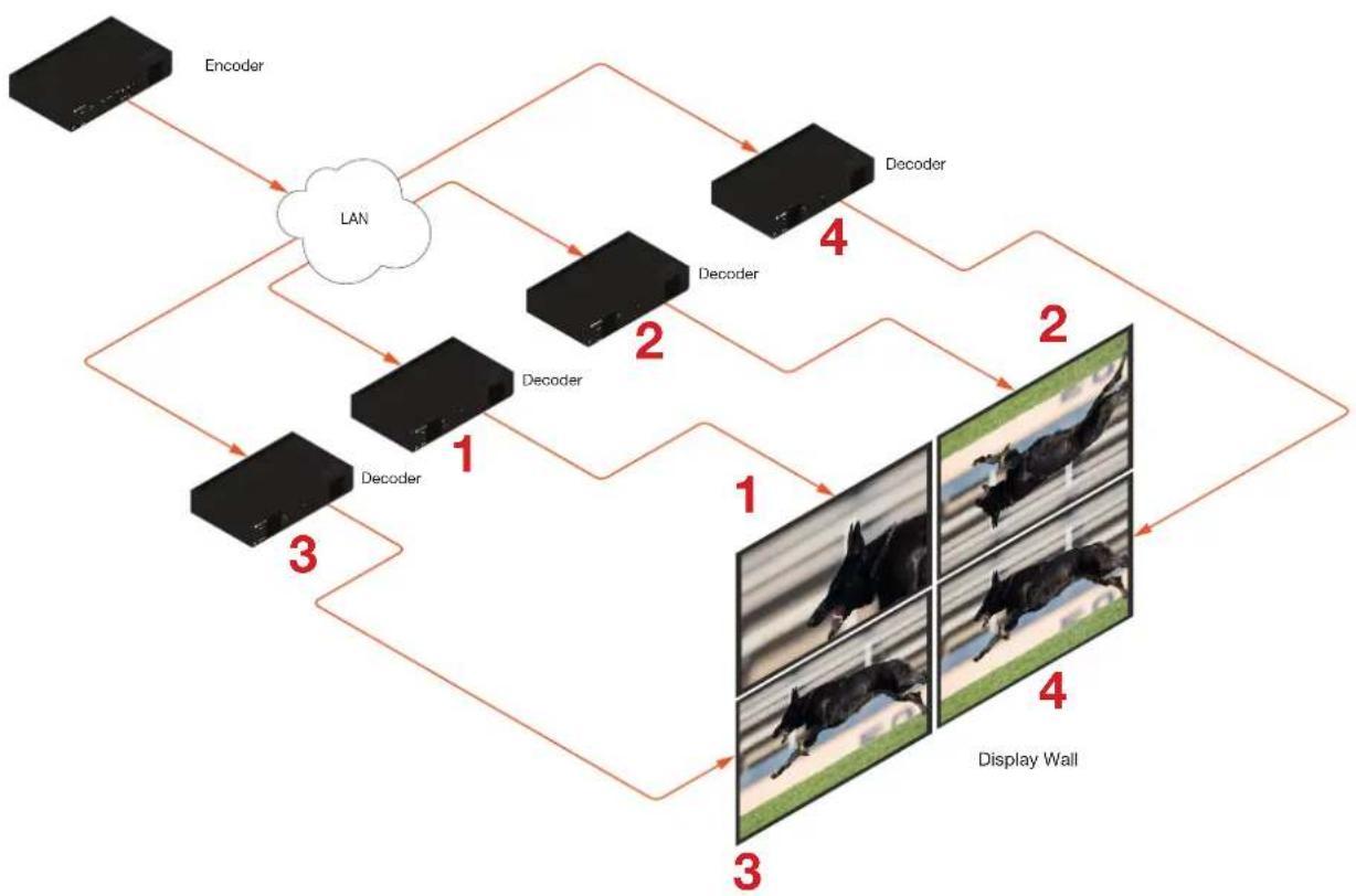
Below, four decoders are subscribed to a single encoder and are displaying the same image on all four displays. The video source is 3840 x 2160. In order to create a single image using all four displays, each source image will need to be cropped and scaled to one-fourth of the total image resolution. The “crop and scale” feature will be used to provide the correct output. Also note that the top two displays have been accidentally mounted upside-down. The “rotate” feature can be used to correct such a scenario and will be illustrated in the following procedure.
flowchart
graph TD
    A["Encoder"] --> B["LAN"]
    B --> C["Decoder 1"]
    B --> D["Decoder 2"]
    B --> E["Decoder 3"]
    C --> F["Display Wall 1"]
    D --> G["Display Wall 2"]
    E --> H["Display Wall 3"]
    F --> I["Display Wall 4"]
    G --> I
    H --> I
Note that the order in which each image is cropped, scaled, and/or rotated is arbitrary. In this example, the configuration process will begin with Display 1, in the top left.
- Login to AMS. Refer to Accessing Decoders in AMS (page 19) if necessary.
- Click HDMI OUTPUT in the menu bar.
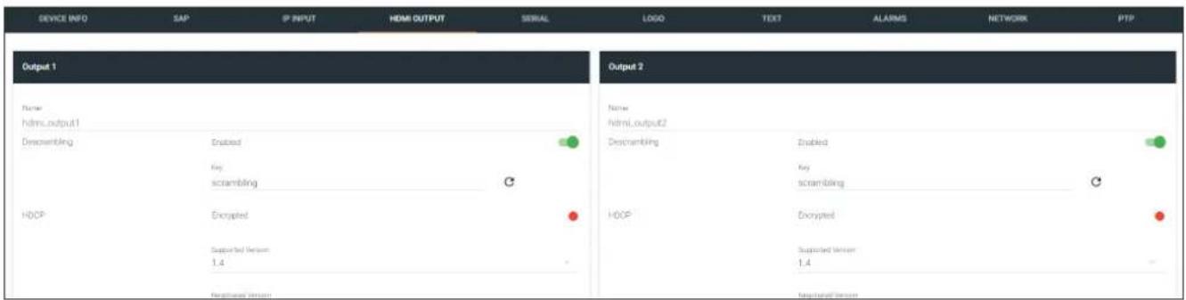
- Locate the Resolution option, in the Video section, and select 1920x1080. This will scale the output resolution from each decoder to 1920x1080.
| Audio | Auto |
| 4096x2160 | |
| 3840x2160 | |
| 1920x1200 | |
| 1920x1080 | |
| 1680x1050 | |
| 1600x900 | |
| 1400x1050 | |
| 1440x900 | |
| 1280x1024 | |
| 1280x800 | |
| 1280x768 | |
| 1280x720 | |
| 1024x768 | |
| Active Input ip_input3 | |
| Status No active audio | |
| Mute |
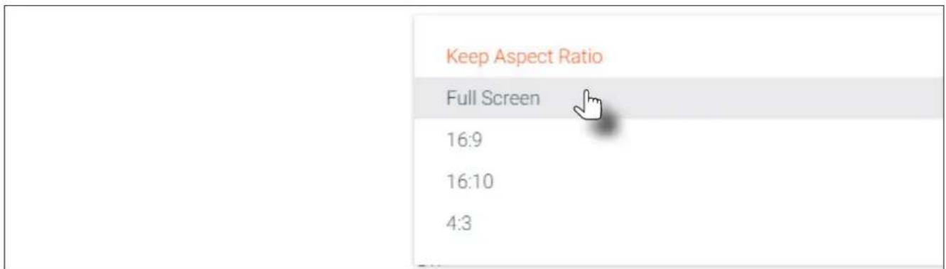
- Click the Stretch/Crop Mode drop-down list and select fullscreen. This guarantees that the image will fill the screen.
- Click the Enable toggle to activate the Video wall option. Once enabled, the Video wall section will be expanded and display all available options.
| No active video | ||
| Stretch/Crop ModeFull Screen | ||
| Resolution1920x1080 | ||
| Slate ModeOff | ||
| Video Wall | Enable |  |
| UnitPixels | ||
| Display Width1920 | ||
| Display Height1080 | ||
- Enter the horizontal and vertical resolution of the display in the Width and Height fields. This is the size of the source to be used for this window of the video wall. The table below, lists width and height examples for a 2x2 video wall, with the specified source resolution.
| Source resolution Width Height | ||
| 3840 x 2160 (UHD) 1920 1080 | ||
| 1920 x 1080 (1080p) 960 540 | ||
Since the example source is 3840 x 2160, the width and height for the Display 1 (upper-left corner) needs to be set 1920 and 1080, respectively, as shown below.
| Video Wall | Enable |
| Unit | |
| Pixels | |
| Display Width | |
| 1920 | |
| Display Height | |
| 1080 |
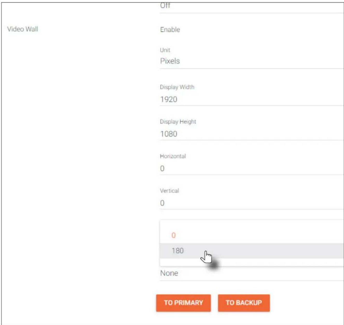
- Enter the number of video wall rows in the Horizontal field and the number of columns in the Vertical field. These values are the pixel start position (upper left most pixel). The table below, lists left and right coordinates for a 2x2 video wall, with the specified source resolution.
| Source resolution Upper Left Upper Right Lower Left Lower Right | |||
| 3840 x 2160 (UHD) 0, 0 1920, 0 0, 1080 1920, 1080 | |||
| 1920 x 1080 (1080p) 0, 0 960, 0 0, 540 960, 540 | |||
- Click the Rotation drop-down list to select the rotation angle of the image. In this example, select 180 from the drop-down list. The image will be flipped, vertically.
Basic Operation
The image on Display 1, as shown below, has been cropped and rotated and now is displayed correctly.
-
Click the SAVE button at the bottom of the screen to accept changes.
-
Repeat steps 1 through 9 for decoders 2, 3, and 4. Note that in this example, at Step 10, decoders 3 and 4 will not require any rotation. In this case, make sure the Rotation option is set to 0.
flowchart
graph TD
    A["Encoder"] --> B["LAN"]
    B --> C["Decoder 1"]
    B --> D["Decoder 2"]
    B --> E["Decoder 3"]
    C --> F["Display Wall 4"]
    D --> F
    E --> F
    F --> G["Display Wall 3"]
    style A fill:#000,stroke:#fff,color:#fff
    style B fill:#fff,stroke:#000
    style C fill:#000,stroke:#000
    style D fill:#000,stroke:#000
    style E fill:#000,stroke:#000
    style F fill:#fff,stroke:#000
    style G fill:#fff,stroke:#000
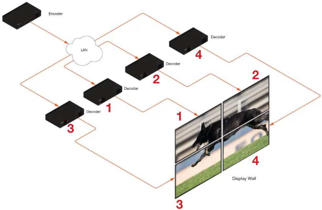
Once all four decoders have been properly configured, the image will be correctly displayed across all four displays:
flowchart
graph TD
    A["Encoder"] --> B["LAN"]
    B --> C["Decoder 1"]
    B --> D["Decoder 2"]
    B --> E["Decoder 3"]
    C --> F["Display Wall 4"]
    D --> F
    E --> F
    F --> G["Display Wall 3"]
    style A fill:#000,stroke:#fff,color:#fff
    style B fill:#fff,stroke:#000
    style C fill:#000,stroke:#fff,color:#fff
    style D fill:#000,stroke:#fff,color:#fff
    style E fill:#000,stroke:#fff,color:#fff
    style F fill:#000,stroke:#fff,color:#fff
    style G fill:#000,stroke:#fff,color:#fff
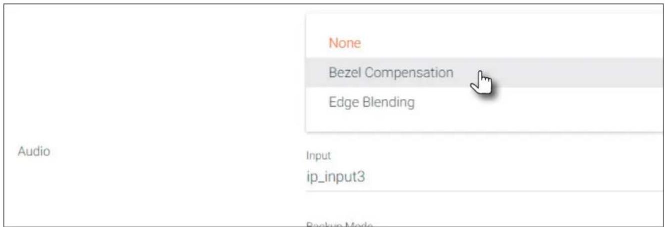
- Check the image, on each display, and make sure they are aligned correctly with the other images on the video wall. Use the Edge Compensation drop-down list to select the desired bevel compensation. See the next page for more information.
Bezel Compensation
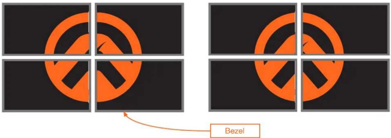
Displays have a region where video is not displayed, called the bezel. This can cause display issues when creating video walls. Bezel compensation takes this area into account when a single video source is mapped across multiple displays. Bezel compensation can be adjusted at any time.
The illustration on the left shows a simple 2x2 video wall without bezel compensation. Note how the Atlona logo is stretched, horizontally. On the right, bezel compensation is used to correct the “distorted” image.
Image without bezel compensation Image with bezel compensation applied
- Select Bezel Compensation from the Edge Compensation drop-down list.
- Enter the Top, Bottom, Left, and Right values, as desired. Values can be entered in pixels, inches, or millimeters.
- Click the SAVE button at the bottom of the screen to accept changes.
Using Velocity™
The following section provides instructions on creating and using video walls with the Atlona Velocity Control Software. Familiarity with the Velocity software is assumed. Refer to the Atlona Velocity User Manual for more information, if necessary.
- Launch a web browser and enter the IP address of AMS, in the address bar.
- Enter the required login credentials.
- Click the Login button.
- The Velocity Dashboard will be displayed.
- Click the ≡icon, in the upper-left corner, to display the fly-out menu.
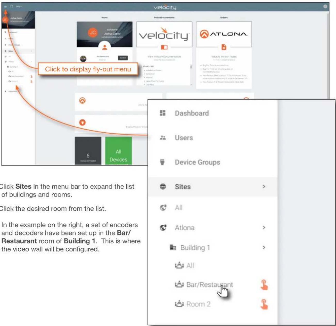
- Click Sites in the menu bar to expand the list of buildings and rooms.
- Click the desired room from the list.
In the example on the right, a set of encoders and decoders have been set up in the Bar/Restaurant room of Building 1. This is where the video wall will be configured.
- The Modify Room screen will be displayed. Click the Add Technology icon in the top far-right corner of the screen. This icon is represented by the + sign.
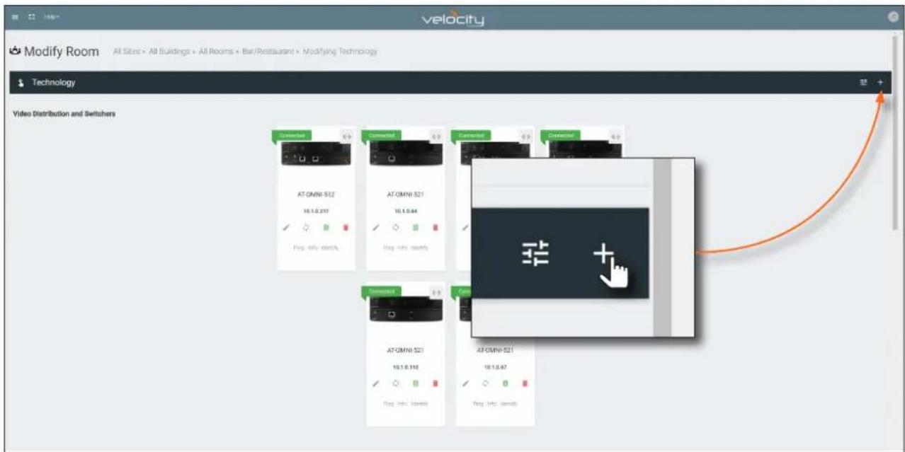
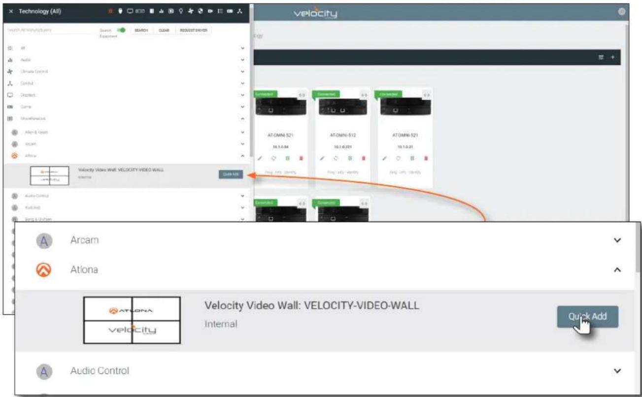
- The Technology fly-out menu will be display.
- In the fly-out menu, click Miscellaneous > Atlona > to expand the Atlona technology menu.
- Click the Quick Add button for Velocity Video Wall: VELOCITY-VIDEO-WALL. The video wall technology will be added to the room.
- Scroll down to the bottom of the page and locate the Velocity Video Wall driver.
- Click the Edit icon. This icon is represented by a pencil.
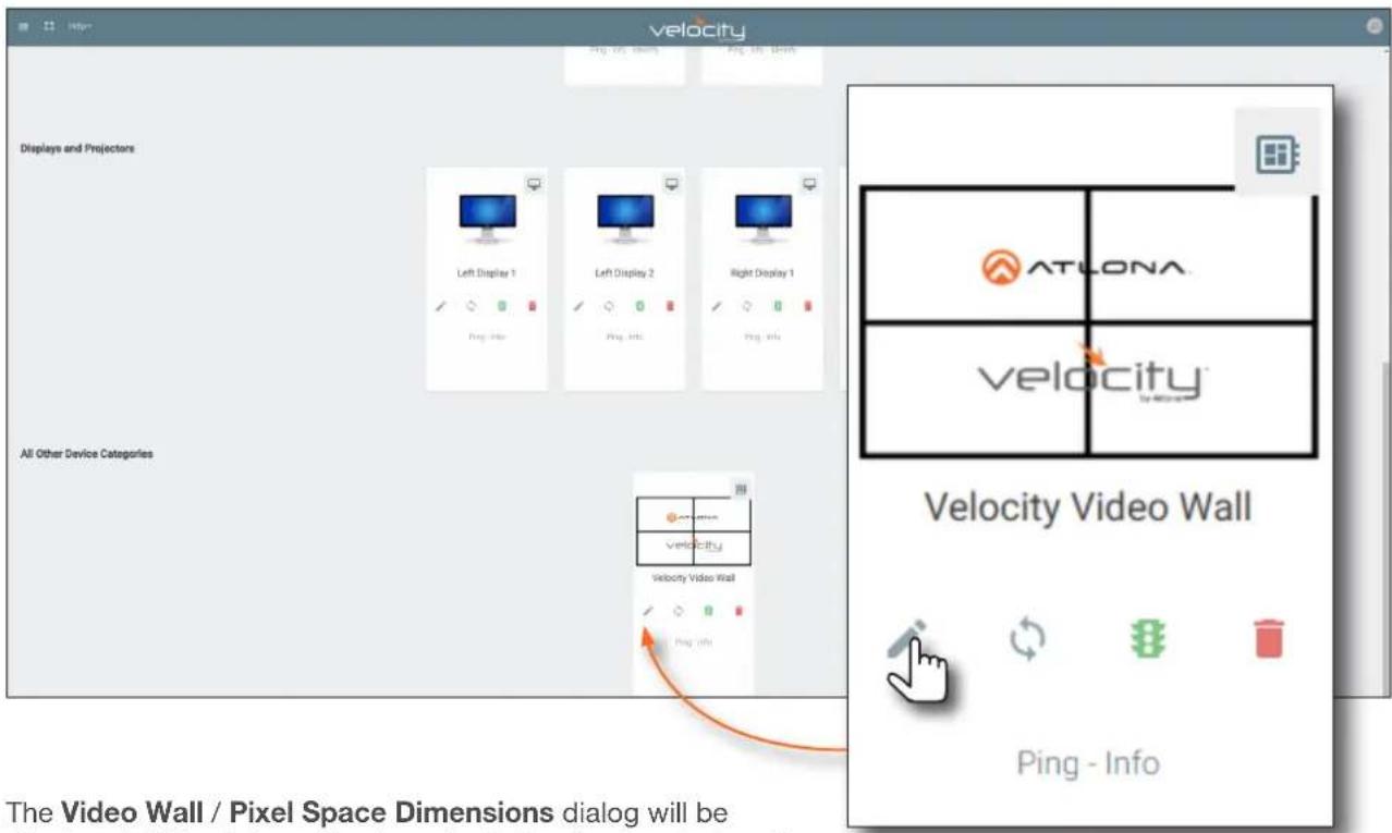
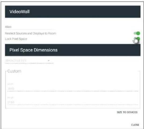
- The Video Wall / Pixel Space Dimensions dialog will be displayed. This dialog will automatically be displayed when the video wall driver is edited for the first time.
The default video wall dimensions are set to 3840 x 2160. To modify the video wall size, follow steps 14a through 14e. To continue with the default video wall dimensions, click the CLOSE button and go to step 15.
a. Click the Lock Pixel Space toggle switch to disable it. When disabled, the toggle switch will turn gray.
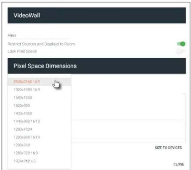
b. Under Pixel Space Dimensions, click the drop-down list to select the desired video wall dimensions.
Basic Operation
c. To create a custom size for the video wall, enter the desired dimensions under the Custom section. Enter the width and height directly, or use the spinner controls at the far end of each field, to adjust the values.
d. Save the video wall dimensions by clicking the Lock Pixel Space toggle switch to enable it.
e. Click the CLOSE button to dismiss the dialog.
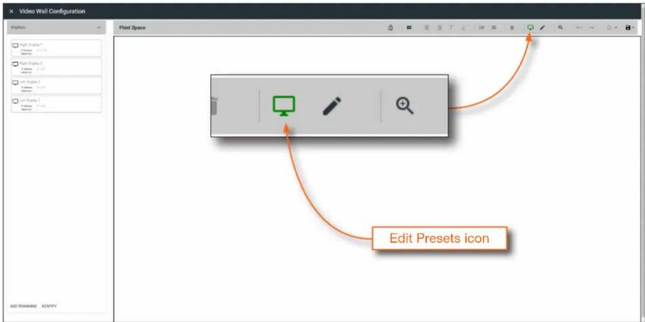
- The Video Wall Configuration screen will be displayed and will automatically be set to "edit mode". In this mode, the Edit Presets icon in the menu bar will be green.
- Under the Displays window, on the left side of the screen, drag and drop the desired displays to the to Pixel Space window.
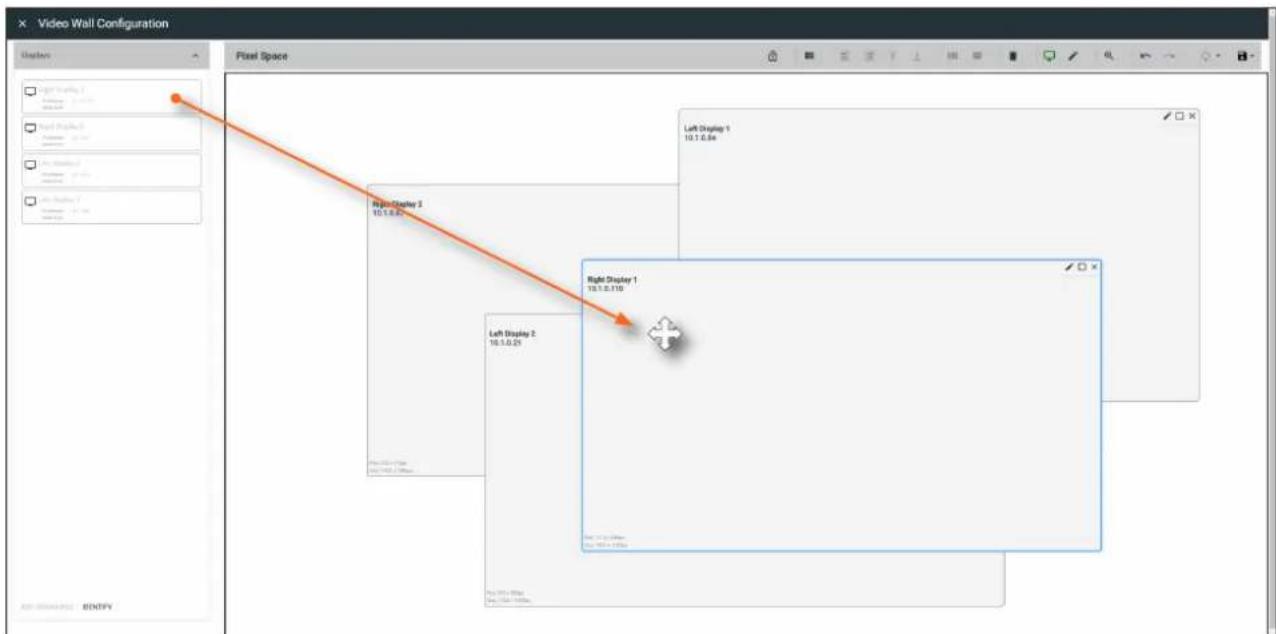

NOTE: The order in which the displays are placed in the Pixel Space window is not important and both the number of displays and how they are arranged can always be changed at a later time.
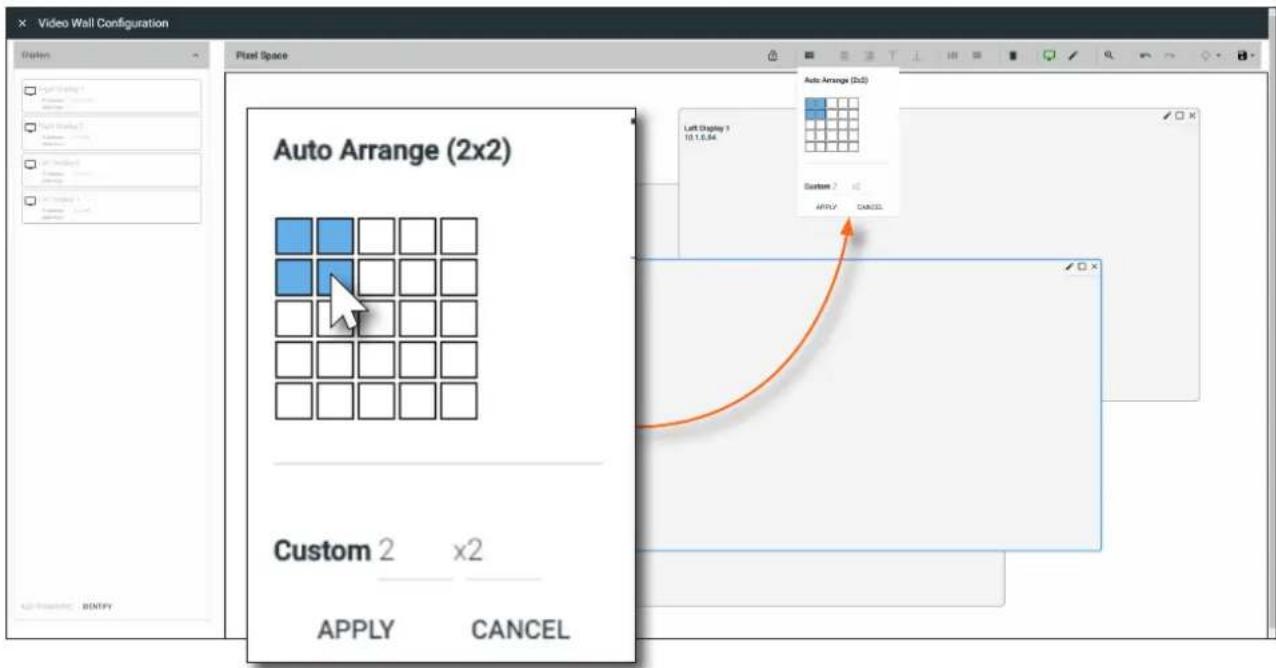
- Click the Auto Arrange icon in menu bar at the top of the Pixel Space window. Move the mouse within the Auto Arrange pop-up dialog to adjust the size of the video wall. Click to commit the selection. In this example, a 2x2 video wall will be created.
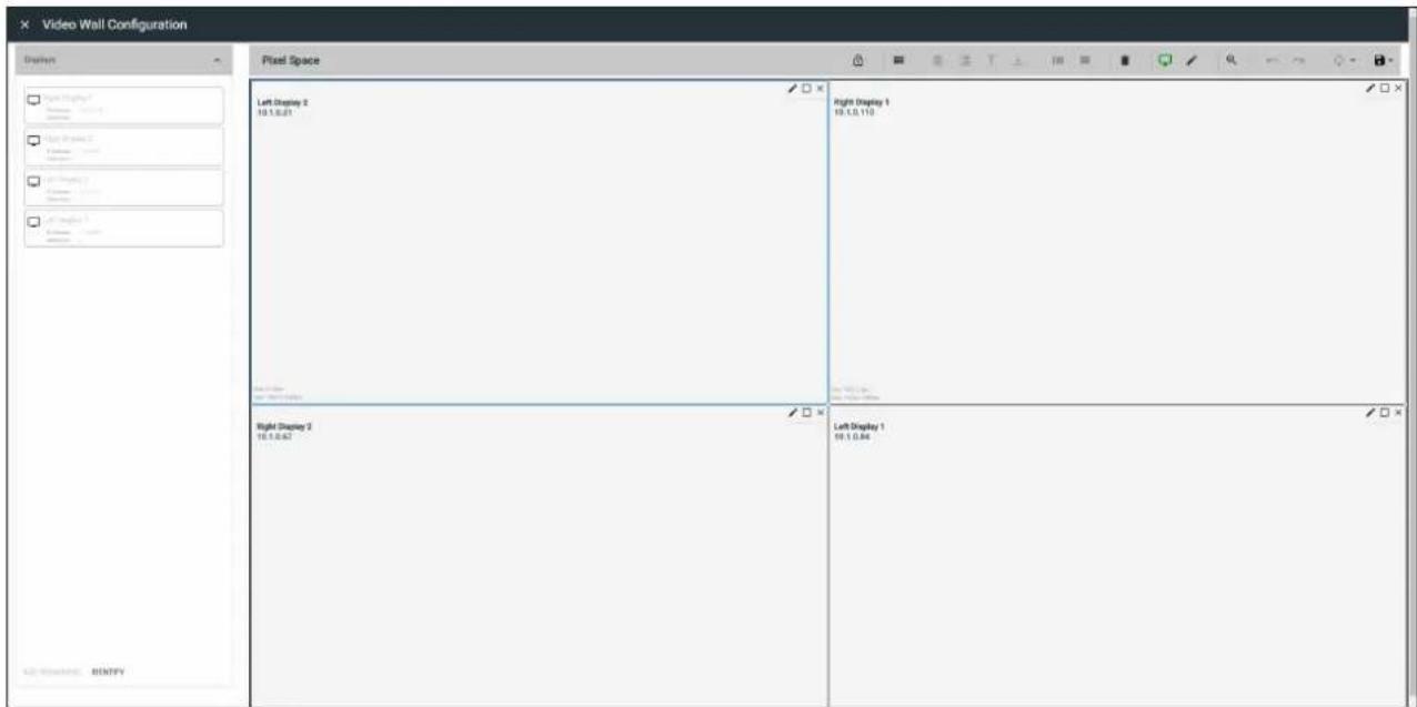
Once Auto Arrange has been applied, the Pixel Space window will appear similar to the following. It should be noted that each display can be rearranged if necessary. To reposition displays, click and drag them to the appropriate places, within the Pixel Space window. Note that each display is identified with a name and an IP address, in the upper-left corner. Refer to the Atlona Velocity User Manual for more information on naming devices.
Basic Operation
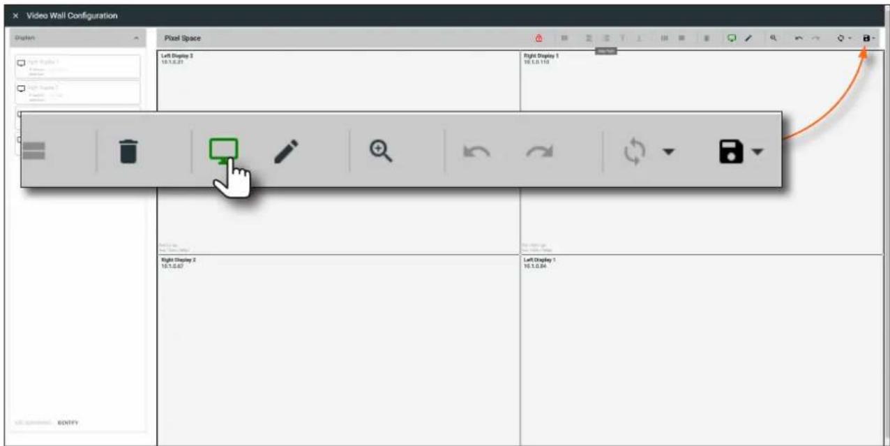
- Click the Lock Displays icon in the menu bar of the Pixel Space window. This is optional. However, enabling this feature will prevent accidental repositioning of the displays, during the configuration procedure. When locked, this icon will turn red. To unlock the displays (for adjustment purposes), click the Lock Displays icon again.
- Click the Save icon in the upper-right corner of the Pixel Space window. This will save the current layout.
- Click the Edit Presets icon to switch to "live mode".
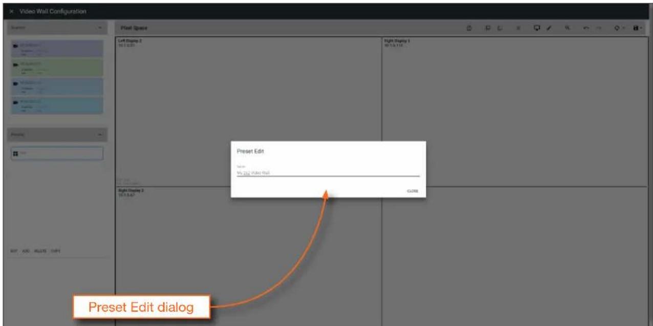
- Enter than name of the preset in the Preset Edit dialog.
- Click the CLOSE button to save the preset name and dismiss the dialog.
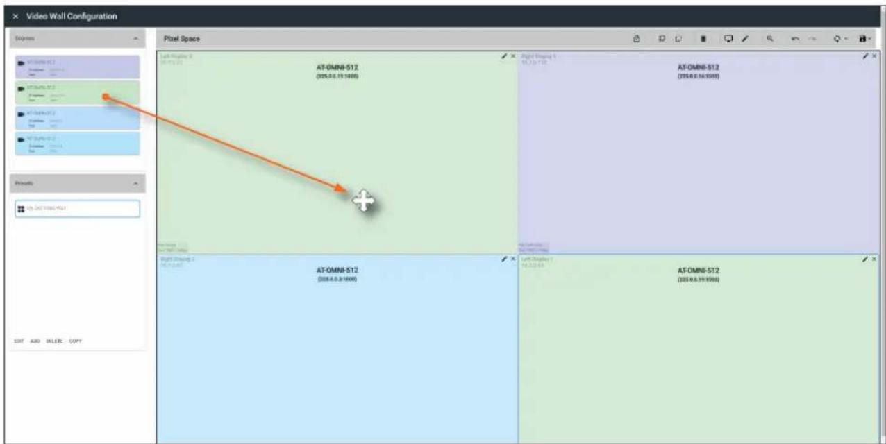
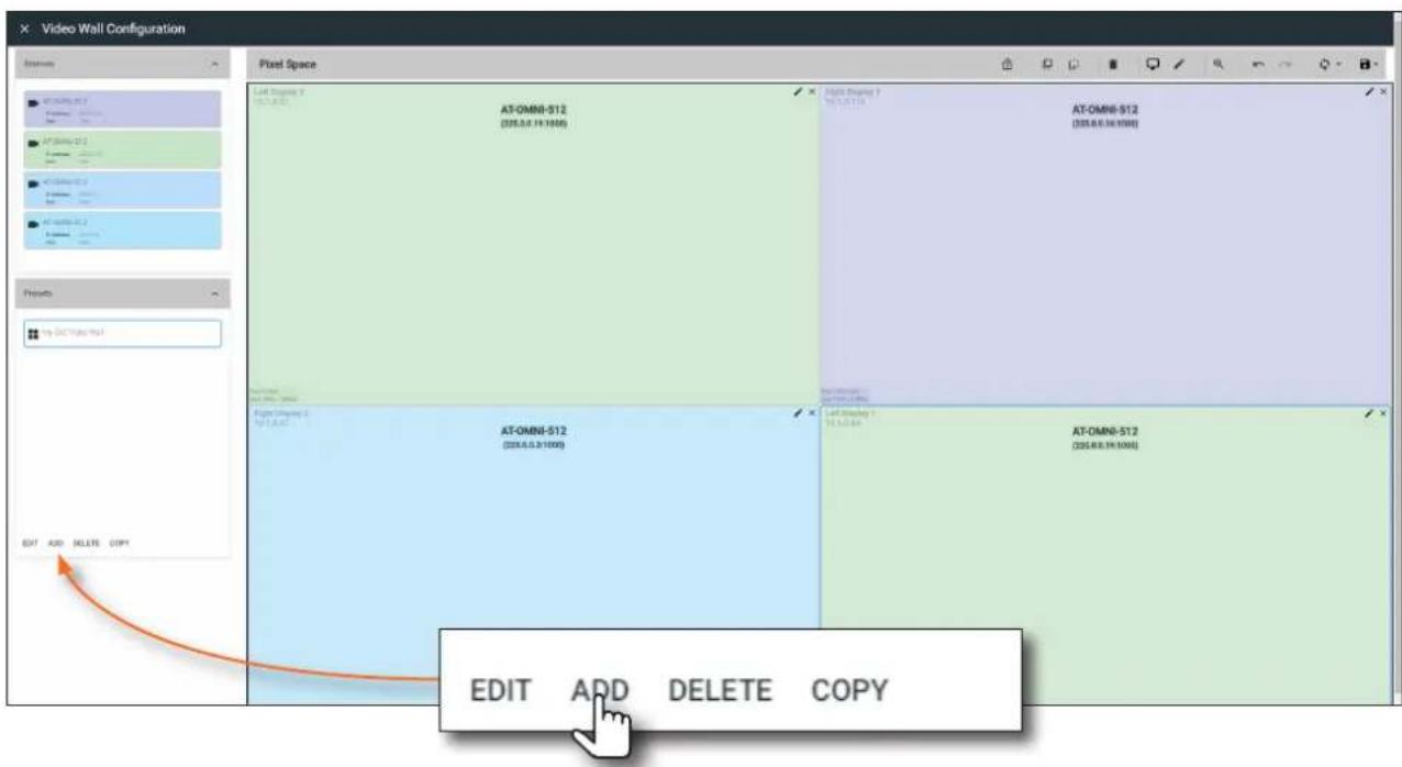
- Under the Sources window, on the left side of the screen, drag and drop the desired source(s) to each display in the Pixel Space window. Note that more than one source can be mapped to each display. For example, in the illustration below, the AT-OMNI-512 (225.0.0.19, port 1000) has been mapped to both Left Display 2 (upper-left corner) and Left Display 1 (lower-right corner).
Sources can also be re-sized "on the fly" to achieve the desired presentation. To re-size a source, click and drag the source window horizontally, vertically, or diagonally. Release the mouse to commit the changes. Refer to the Atlona Velocity User Manual for more information on manipulating source windows.
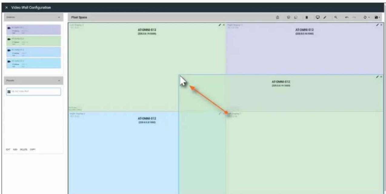

NOTE: When source windows are resized, they will "snap" to the nearest vertical or horizontal border, depending upon the direction that the mouse cursor is being moved. Source windows cannot occupy fractions of a display window.
Basic Operation
- Click ADD, under the Presets section, on the left side of the screen, to create additional presets.
- Repeat steps 21 through 23 to create the preset. Once the desired presets have been created, click the preset name under the Presets section to recall it. The video wall will be updated with the selected preset.
Refer to the Atlona Velocity User Manual for more information on using and recalling presets.
Configuring Redundant Streams
OmniStream decoders have the ability to identify missing streams, should an input be disconnected from the encoder, and will recover the image almost instantaneously. The decoder can access the same stream from two separate multicast addresses and switch between them, when necessary.
- Login to AMS and access the Virtual Matrix. Refer to The Virtual Matrix (page 85) for more information.
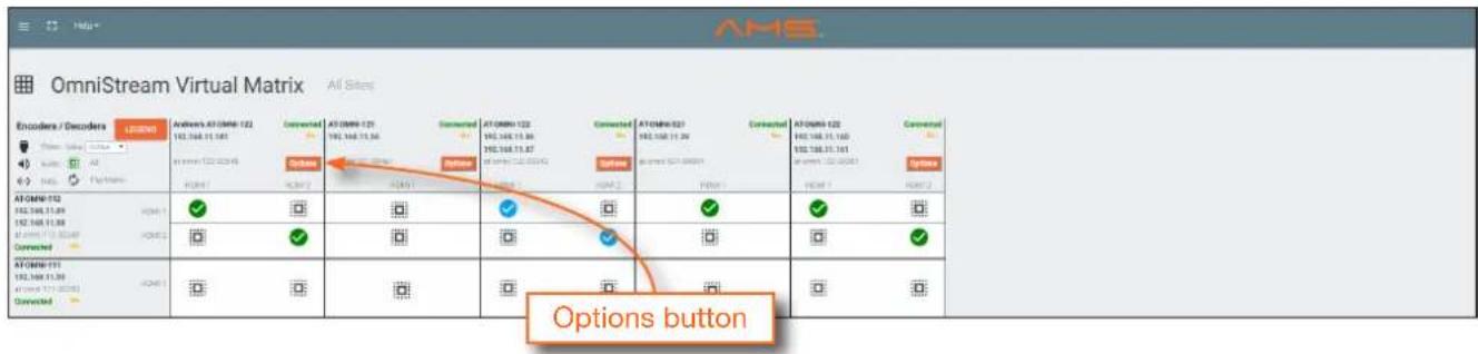
- In the Virtual Matrix, locate the decoder to be configured for redundancy.
- Click the Options button for the desired decoder. In this example, the decoder in the upper-left corner of this matrix will be used. The Crosspoint Options dialog box will be displayed.
- Select the backup mode for Video Redundancy and/or Audio Redundancy from the Backup Mode drop-down lists. Refer to the table below, for a listing and description of the available modes.
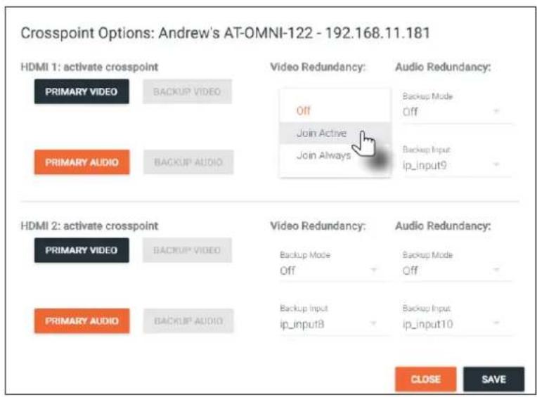
| Mode Description | |
| Off Redundancy | off; output will never switch to the backup stream. |
| Join Active The decoder | sends a join request only when the primary stream is lost or if the decoder is manually switched to the backup stream. Switch time will not exceed 5 seconds.* |
| Join Always | The decoder joins both the Primary and Backup stream at the same time. Switch time will not exceed 0.5 seconds. |
* Switching time will be dependent upon the network switch that is used, as well as the number of hops between encoders and decoders on the network.
Redundancy Grace Period
During use, the decoder can be switched to another multicast stream. However, if the decoder encounters a missing stream, during the switch and when redundancy is enabled, then this will cause the decoder to automatically failover to the multicast source configured as the backup. To prevent the decoder from automatically making the redundancy switch, when redundancy is enabled, a grace period can be entered. By default, the grace period is set to 0 seconds. If set to 0 seconds, automatic failover will occur if the stream is interrupted, for any reason. Refer to Configuring Redundant Streams (page 54) for more information on enabling or disabling redundancy.
- Login to AMS. Refer to Accessing Decoders in AMS (page 19) if necessary.
- Click HDMI OUTPUT in the menu bar.
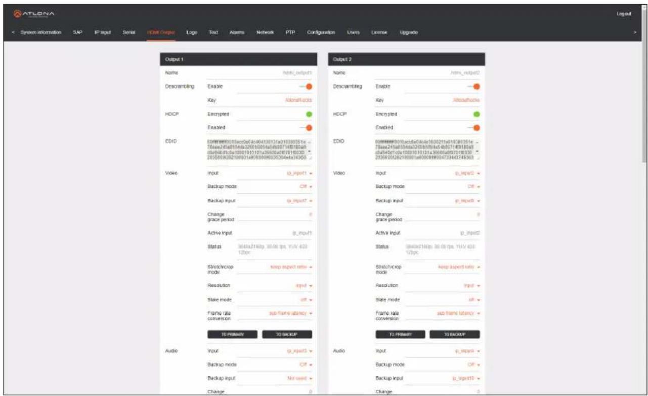
- Locate the Change grace period field.
- Enter the desired value, in seconds. By default, this value is set to 0.
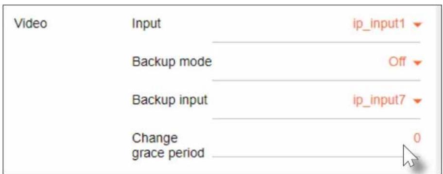
- Click the Save button, at the bottom of the Output section.
The AMS Interface
Device Info page
The Device Info page provides general information about the decoder.
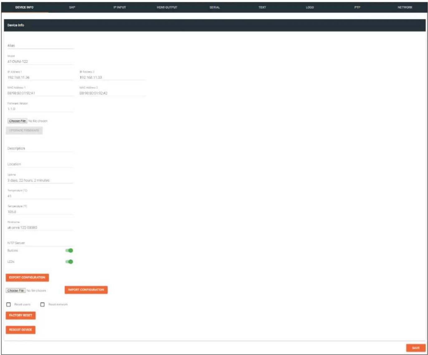
Alias
Enter a name for the unit in this field. This is optional.
Model
The model number of the unit.
Model Description
AT-OMNI-121 Single-channel decoder
AT-OMNI-122 Dual-channel decoder
The AMS Interface
IP Address 1 / IP Address 2
Displays the IP address of the ETHERNET 1 and ETHERNET 2 ports, respectively. Single-channel encoders will only have a single IP address.
MAC Address 1 / MAC Address 2
Displays the MAC address of the ETHERNET 1 and ETHERNET 2 ports, respectively. Single-channel encoders will only have a MAC address.
Firmware version
The version of firmware that the unit is running. Always make sure the latest version of firmware is installed.
Choose File
Click this button to select the firmware file when upgrading the firmware.
UPGRADE FIRMWARE
Click this button to begin the firmware upgrade process.
Description
Provides the option of assigning descriptive name to the unit.
Location
Provides the option of assigning descriptor for the location of the unit.
Uptime
Time elapsed since the last reboot operation.
Temperature (°C)
The current internal temperature of the unit, in degrees Celsius.
Temperature (°F)
The current internal temperature of the unit, in degrees Fahrenheit.
Hostname
The hostname of this unit. This can be changed if desired. By default, the host name is automatically created using the model of the unit and adding the last five digits of the unit serial number.
NTP Server
Specify the desired NTP server in this field. This provides timestamps for any logs and alarms.
Buttons
Disabling this feature will lock the ID button on the front panel. This is enabled by default.
LEDs
Disabling this feature will turn off all LED indicators on the front panel. This is enabled by default.
Click this button to export the current configuration settings of the encoder to a local file on the computer.
The configuration file will be saved in .json format. The default file name will be in the format: AT-OMNI-1xx_settings_[dd-mm-yyyy]_xx_xx.json.
Choose File
Click this button to select the desired configuration file to be uploaded to the encoder. Once the file is selected, click the IMPORT CONFIGURATION button to upload the file.
IMPORT CONFIGURATION
Click this button to upload the configuration file to the decoder.
FACTORY RESET
Click this button to reset the encoder to factory-default settings. When performing a factory reset, the following options can be selected, by clicking the check box. If no options are selected, then the encoder is reset with no factory-default settings.
| Option Description | |
| None Checked Resets the encoder with no factory-default settings. | |
| Reset User Resets the encoder to factory-default settings and resets custom user information. | |
| Reset Network Resets the encoder to factory-default settings and resets network information. | |
| Reset Defaults | Resets the encoder to factory-default settings. In addition, static multicast addresses are configured. This option can be used to configure a single encoder to transmit to any number of decoders without using the Virtual Matrix within AMS. NOTE:This will not work for multiple encoders on the same network. NOTE:This will not work for multiple encoders on the same network. |
REBOOT
Click the Reboot button to perform a soft reboot of the encoder.
SAP page
The SAP page enables or disables the Session Announcement Protocol protocol. Enabling SAP configures the decoder to look for SAP messages from encoders on the network that are configured to send SAP. Any messages that are discovered will be displayed here.
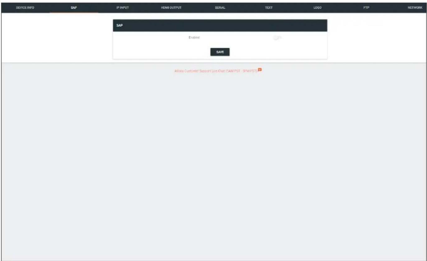
Enabled
Click this toggle switch to enable or disable SAP. If enabled, the toggle switch will be green. Click the SAVE button to commit changes.
IP Input page
The IP Input tab provides configuration of each input, the assigned multicast address(es), and ports.
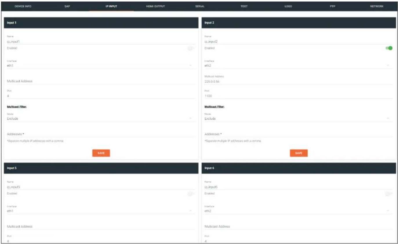
Name
The name used by AMS to identify the IP input.
Enable
Click this checkbox to enable the IP input.
Interface
Select the physical interface, that will be used to carry the multicast traffic, from this drop-down list. When using a single-channel decoder, only eth1 will be available.
| Input Description | |
| eth1 ETHERNET | 1 port |
| eth2 ETHERNET | 2 port |
Multicast Address
Enter the multicast address of the decoder stream.
Mode
Click this drop-down list to select the mode. Mode can be set to exclude or include and is specifically used when using Source Specific Multicast (SSM). SSM will only function if the network is properly set up to support it.
| Mode Description | |
| exclude Multicast | content coming from the source mentioned in the Addresses section will be excluded (blocked). |
| include | Multicast content coming from the source mentioned in the Addresses section, on the next page, to be streamed to the decoder. |
Addresses
Enter the IPv4 address of the encoder(s) in this field and is used as the SSM include/exclude list. Use the comma delimiter to separate multiple IP addresses. When using non-SSM networks, this field is ignored.
Port
Enter the multicast UDP listening port in this field.
HDMI Output page
The HDMI Output tab provides options to configure the output streams.
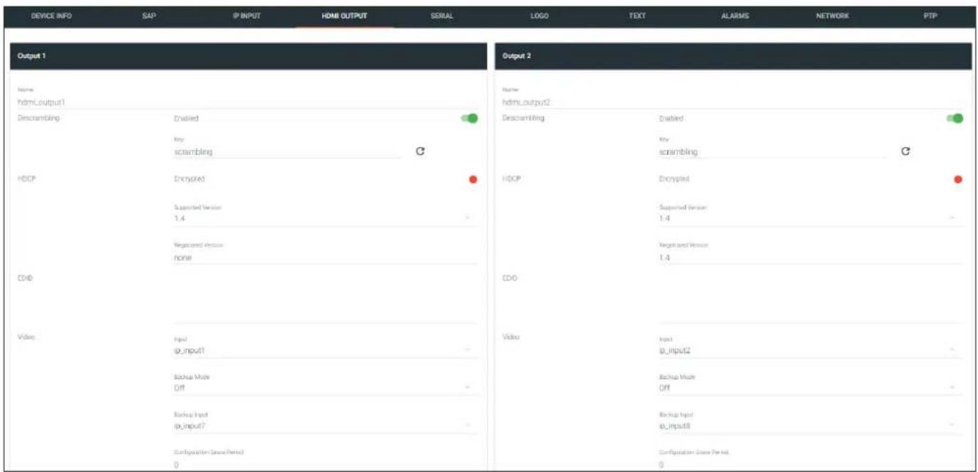
Output
Name
The name used by AMS to identify the HDMI output.
Enabled
Click this toggle switch to enable or disable scrambling on the decoder. When enabled, the toggle switch will be green.
Key
Enter the scrambling key in this field. The scrambling key must be ASCII and must contain a minimum of eight characters. Special characters and spaces are not permitted.
Encrypted
Indicates if the content is HDCP-encrypted or not. If true, then HDCP content is being passed in to the decoder and this indicator will be colored green.
Supported Version
Click this drop-down list to select the desired HDCP version. If set to none, then the sink is reported as "non-compliant" and will receive non-HDCP content.
| Input Description | |
| none The decoder will receive non-HDCP content. | |
| 1.4 The decoder will receive HDCP version 1.4 content. | |
| 2.2 The decoder will receive HDCP version 2.2 content. |
Negotiated Version
The version of HDCP being received.
Video
Input
Click this drop-down list to select the desired primary video input. Select generator to use the internal signal generator. Select the Not Used option to leave the video input unassigned.
Backup Mode
Select the backup mode from this drop-down list.
| Mode Description | |
| Off Backup source | is disabled; join request not sent. |
| Join Active The decoder sends a join request only when the decoder decides to switch between sources.Switch time will not exceed 5 seconds. | |
| Join Always | The decoder always joins to the backup source. Switch time will not exceed 0.5 seconds. |
Backup Input
Select the secondary video backup IP input from this drop-down list. If the primary IP input is down, then the decoder will automatically switch to this input. Refer to the Backup Mode option, above, for setting the conditions for switching inputs.
Configuration Grace Period
To prevent the decoder from automatically making the redundancy switch, when redundancy is enabled, a grace period can be entered. By default, the grace period is set to zero seconds. If set to zero seconds, automatic failover will occur, if the stream is interrupted for any reason. Refer to Configuring Redundant Streams (page 63) for more information.
Active Input
Displays the currently active IP Input.
Status
This field will display the output resolution. If no video is present, then this field will display No Active Video.
Stretch / crop mode
Click this drop-down list to select the aspect ratio.
| Mode Description | |
| keep aspect ratio | Aspect ratio is preserved; the output on the decoder will be the same as the input on the encoder. |
| fullscreen | Stretches the image to fill the screen. In some cases this can distort (“stretch”) the image. |
Resolution
Click this drop-down list to select the desired output resolution. This is a scaler feature which can either upscale or downscale the output on the decoder. If Input is selected, then no scaling will be applied to the output. Select Auto to use the EDID of the sink device to determine the output resolution.
| Resolutions | |
| Input 1440 x 1050 | |
| Auto 1440 x 900 | |
| 4096 x 2160 1280 x 1024 | |
| 3840 x 2160 1280 x 800 | |
| 1920 x 1200 1280 x 768 | |
| 1920 x 1080 1280 x 720 | |
| 1680 x 1050 1024 x 768 | |
| 1600 x 900 | |
Slate Mode
Click this drop-down list to select the slate mode. Refer to Slate / Logo Insertion (page 44) for more information.
| Mode Description | |
| Off Disables the image from being displayed. | |
| Manual | Stretches the image to fill the screen. In some cases this can distort (“stretch”) the image. |
| Auto | The image will only be displayed when the source signal is lost. For example, this mode is useful in conference room applications for displaying system instructions when no sources are connected. |
Enable
Click this toggle switch to enable or disable the video wall feature. When enabled, the toggle switch will be green. Refer to Creating Video Walls (page 48) for more information.
To Primary
Click this button to make the video use the Primary IP Input.
To Backup
Click this button to force the video stream to fall over to the Backup IP Input (if redundancy is configured).
Audio
Input
Click this drop-down list to select the primary audio IP input. Select the Not Used option to leave the audio input unassigned.
Backup Mode
Click this drop-down list to select the audio backup mode.
| Mode Description | |
| Off Backup source | is disabled; join request not sent. |
| Join Active The decoder sends a join request only when the decoder decides to switch between audio sources. Switch time will not exceed 5 seconds. | |
| Join Always | The decoder always joins to the backup audio source. Switch time will not exceed 0.5 seconds. |
Backup Input
Select the secondary audio backup IP input from this drop-down list. If the primary IP input is down, then the decoder will automatically switch to this input.
Configuration Grace Period
To prevent the decoder from automatically making the redundancy switch, when redundancy is enabled, a grace period can be entered. By default, the grace period is set to zero seconds. If set to zero seconds, automatic failover will occur, if the stream is interrupted for any reason. Refer to Configuring Redundant Streams (page 63) for more information.
Active Input
Displays the currently active IP Input.
Downmixing
Click this drop-down list to select how LPCM audio will be down-mixed. Note that lossless audio formats cannot be down-mixed.
| Type Description | |
| None Audio is not down-mixed. | |
| Stereo Audio is down-mixed to two-channel stereo. | |
| Auto Display is always on, source audio/video signal switches on/off | |
Enable AES67
Click this toggle switch to enable or disable AES67. When enabled, the toggle switch will be green. Refer to AES67 Audio (page 37) for more information.
Status
This field will display the audio type. If no audio is present, then this field will display No active audio.
Mute
Click this toggle switch to enable or disable the audio output. If enabled, the toggle switch will be green.
Volume
Click the speaker icon on the left to decrease volume. Click the speaker icon on the right to increase volume. Range: 0 to 15.
Analog Input
If analog input is connected to the decoder, then click this toggle switch to use the analog audio input. When enabled, this toggle switch will be green.
Analog Output
If analog output is connected to the decoder, then click this toggle switch to use the analog audio output. When enabled, this toggle switch will be green.
TO PRIMARY
Click this button to make the audio use the Primary IP Input.
TO BACKUP
Click this button to force the audio stream to fall over to the Backup IP Input (if redundancy is configured).
Aux (CEC)
Auto On
Click this toggle switch to enable or disable power-on. When enabled this toggle switch will be green and the power-on command will be sent to the display when an A/V signal is detected.
Projector Cooldown (s)
Enter the time interval, in seconds, before the projector can be powered-off. This time interval prevents the decoder from sending additional commands until the projector has had time to complete its cool-down process.
Standby Timeout
Enter the time interval, in seconds, before the next command can be accepted by the display.
Type
Click this drop-down list to select the display mode.
| Type Description | |
| DispSW AVon Display switches | on/off, source audio/video signal always on. |
| DispSW AVSW Display switches | on/off, source audio/video signal switches on/off. |
| AV SW Display is always on, source audio/video signal switches on/off | |
| Always on Display is always on, source audio/video signal always on. | |
Video Optimization
Video Optimization
As of this writing, this feature is not available within AMS. Refer to Setting the Video Mode (page 43) for more information.
Serial page
The Serial Config tab provides serial port configuration when using control signals.
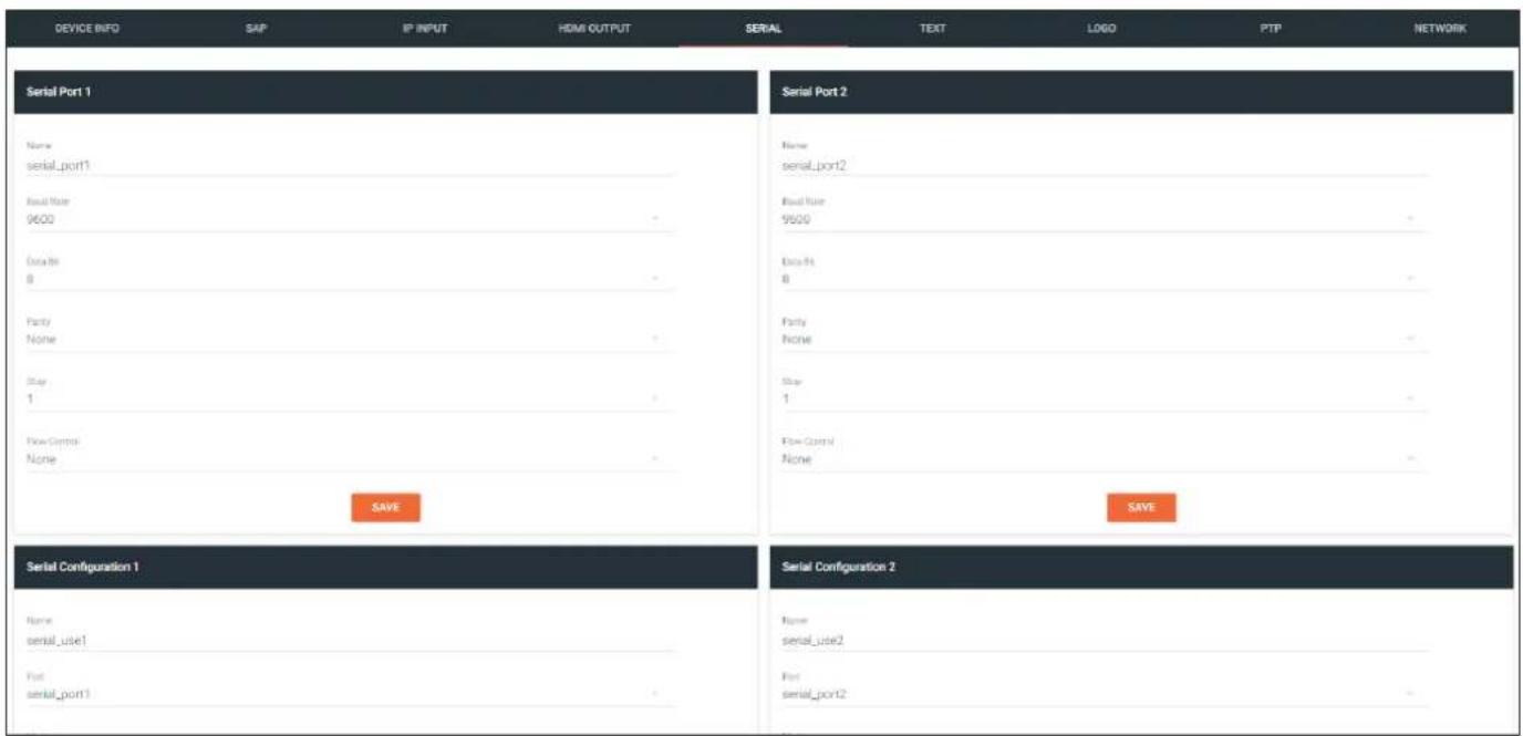
Serial Port
Name
The name used by AMS to identify the serial port.
Supported Modes
Lists the supported protocols.
Mode
Click this drop-down list to select the desired serial mode: Infrared or Serial.
Baud Rate
Click this drop-down list to select the desired baud rate.
Data
Click this drop-down list to select the number of data bits.
Parity
Click this drop-down list to select the parity bit.
Stop
Click this drop-down list to select the stop bit.
Flow
Click this drop-down list to select the type of flow control.

NOTE: The single-channel decoder will only have one Serial Port Configuration section.
Serial Configuration
Name
The name used by AMS to identify the serial port.
Port
Click this drop-down list to select the port: serial_port1, serial_port2, or Not Used.
Mode
Click this drop-down list to select the desired control mode.
Interface Description
cli Displays the command-line interface of the decoder.
Output Serial port will send commands directly to the display device.
tcpproxy Commands are sent over IP but triggered over the serial port.
The following Bidirectional section must be completed if two-way communication, between the encoder and decoder is required. Bidirectional control is only supported for unicast control sources (not multicast).

NOTE: The Bidirectional block will only be displayed if Mode is set to Output.
Interface
Click this drop-down list to select the physical interface: eth1 or eth2.
Interface Description
eth1 ETHERNET 1 port
eth2 ETHERNET 2 port
Destination IP address
Enter the IPv4 address of the encoder in this field.
Destination UDP port
Enter the destination UDP listening port in this field.
Enable
Click this toggle switch to enable bidirectional serial communication. When enabled, the toggle switch will be green.
The AMS Interface
Command
Command
Each of these The Command blocks are used to enter the command string for the desired operation: Display Off, Display On, Volume Down, and Volume Up.
Mode
Click this drop-down list to select where the command will be interpreted.
Interpret on Description
Raw Commands are interpreted at the encoder.
decoder Commands are interpreted at the decoder.
ASCII
Enter the ASCII representation of the command string in this field.
HEX
Enter the hexadecimal representation of the command in this field.

NOTE: When entering the command string, it is not required to enter the string under both the ASCII and HEX fields. The decoder requires that only one field be completed.
Text page
The Text tab provides the ability to configure text scrolling. Refer to Text Insertion (page 46) for more information.
| DEVICE INFO | SAP | IP INPUT | HDMI OUTPUT | SERIAL | TEXT | LOGO | PTP | NETWORK |
| Text 1 | Text 2 | |||||||
| Text Name text_insertion1 | Text Name text_insertion2 | |||||||
| Disabled | Disabled | |||||||
| Text | Text | |||||||
| Scored Speed 0 | Scored Speed 0 | |||||||
| Sequence 0 | Sequence 0 | |||||||
| Color: | Color: | |||||||
| Color white - | Color white - | |||||||
| Red 255 | Red 255 | |||||||
| Green 255 | Green 255 | |||||||
| Blue 255 | Blue 255 | |||||||
| Alpha 255 | Alpha 255 | |||||||
| Location: Horizontal (%) 0 Vertical (%) 0 Size: Match(%) 0 Print(%) 0 Location: Horizontal (%) 0 Vertical (%) 0 Size: Match(%) 0 Print(%) 0 | ||||||||
Text Name
The name used by AMS to identify the text.
Enabled
Click this toggle switch to enable or disable the text. When the toggle switch is green, the text will be enabled.
Text
Enter the desired text in this field.
Scroll Speed
Enter the scrolling speed in this field. Values from -255 to 255 are valid. Negative numbers will scroll the text from left to right. Positive numbers will scroll text from right to left.
Iterations
Enter the number of iterations in the Iteration field. Set this field to 0 (zero) to set the number of iterations to infinity.
The AMS Interface
Color
Red, Green, Blue, Alpha
Enter the RGBA values for each of the respective fields, to specify the color and transparency of the text. Enter the desired value in the Alpha field to control the transparency of the text. A value of 255 is opaque and a value of 0 is transparent. Numbers from 0 to 255 are valid for each of these fields.
Location
Horizontal (%), Vertical (%)
Specify the location of the text in the Horizontal (%) and Vertical (%) fields. Each of these values is based on the horizontal and vertical resolution of the screen.
Size
Width (%), Height (%)
Specify the size of the text in the Width (%) and Height (%) fields. Each of these values is based on the horizontal and vertical resolution of the screen.
Logo page
The Logo tab provides the ability to upload a custom logo. This logo will be displayed when no video signal is detected. Separate logos can be uploaded: one for each channel.
Refer to Slate / Logo Insertion (page 44) for more information on using logos.
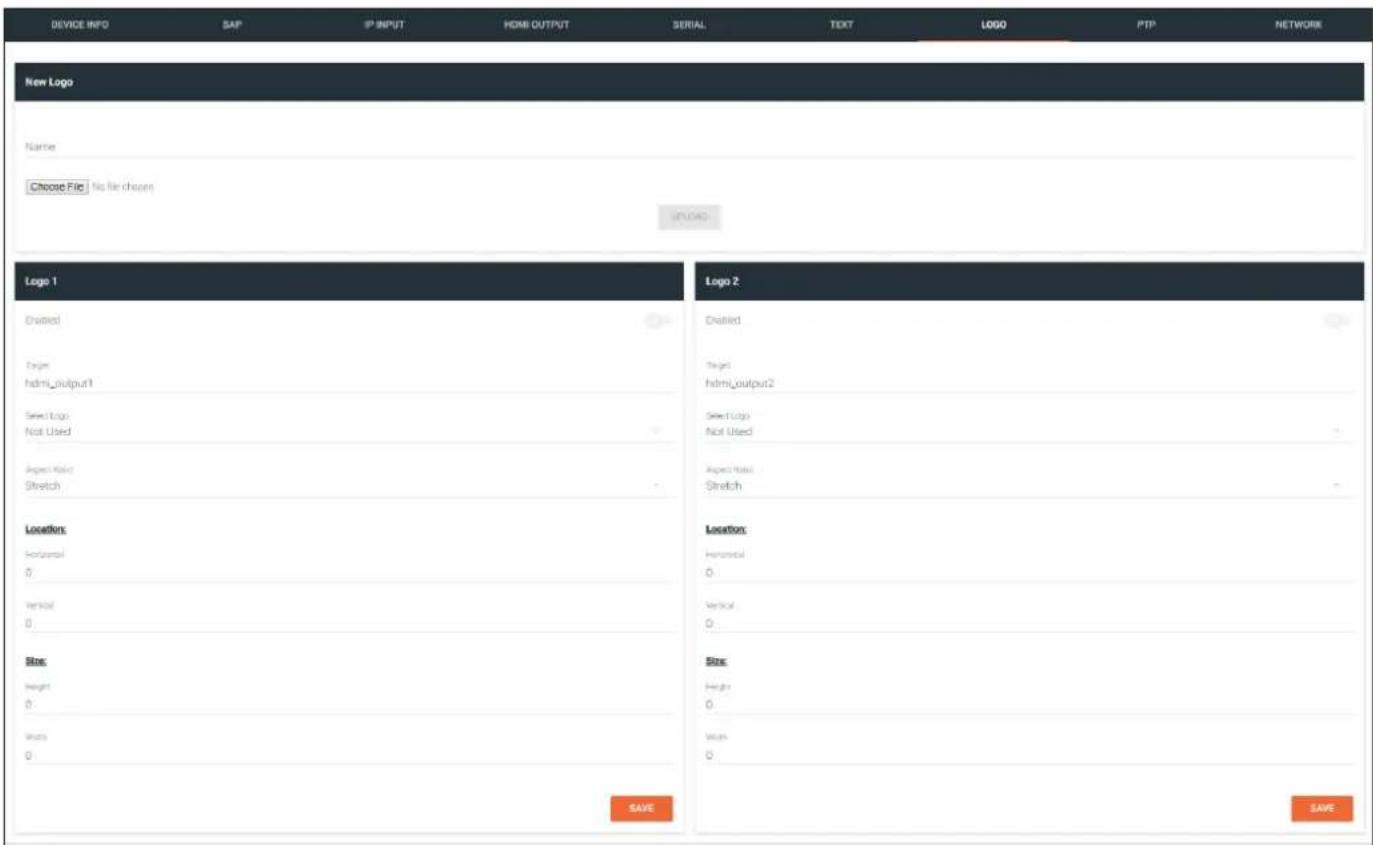
New Logo
Name
Enter a name for the logo in this field.
Choose File
Click this button to select the logo file to be uploaded. Files must be in .png format and must not exceed 5 MB (5210000 bytes) in size. When an image file is uploaded, it will appear in the Logo drop-down list.
UPLOAD
Click this button to upload the logo file to the decoder.
The AMS Interface
Logo
Enabled
Click the toggle switch to enable or disable the logo. If the toggle switch is green, then the logo will be enabled.
Target
The name used by AMS to identify the decoder.
Select Logo
Click this drop-down list to select the desired logo. If no logo files are uploaded, then this will be set to Not Used.
Aspect Ratio
Click this drop-down list to select the type of aspect ratio to be applied to the logo.
Horizontal
Enter the horizontal position of the logo on the screen.
Vertical
Enter the vertical position of the logo on the screen.
Height
Enter the horizontal resolution of the logo, in pixels.
Width
Enter the vertical resolution of the logo, in pixels.

NOTE: Maximum logo resolution (both height and width) is 1/4 of the video resolution.
PTP page
The PTP tab provides options for adjust Precision Time Protocol (PTP) for AES67 audio streams. PTP is used by AES67 to keep all audio streams synchronized.
For a system utilizing PTP, all devices undergo an automatic self-election process to choose the interface to be used as the PTP grandmaster (GM) clock, based on the accuracy of the device's clock and the device's configured priority. A lower priority number means the unit is more likely to get selected as GM.

NOTE: If a new device is added to the network and the GM changes, a brief outage will be experienced while all connected devices synchronize with the new clock. Because of this, Atlona recommends that one unit gets manually defined as the GM and have both Priority 1 and Priority 2 fields be set to 1.
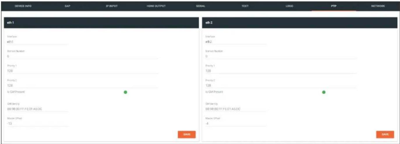
Interface
The name used by AMS to identify the interface.
Domain Number
Enter the domain number in this field. Valid entries are 0 through 127.
Priority 1
Enter the priority number in this field.
Priority 2
Enter the priority number in this field.
Is GM Present
This indicator displays the existence of a grandmaster clock for the specified PTP domain number. If the indicator is green, then the grandmaster clock exists on this interface.
GM Identity
The grandmaster clock identity. If this field is blank, then it means that this interface is the grandmaster clock.
Master Offset
Displays the grandmaster clock offset.
Network page
The Network tab provides the ability to enable or disable DHCP mode for each network interface. When DHCP mode is disabled, the IP address, subnet mask, and gateway must be provided.
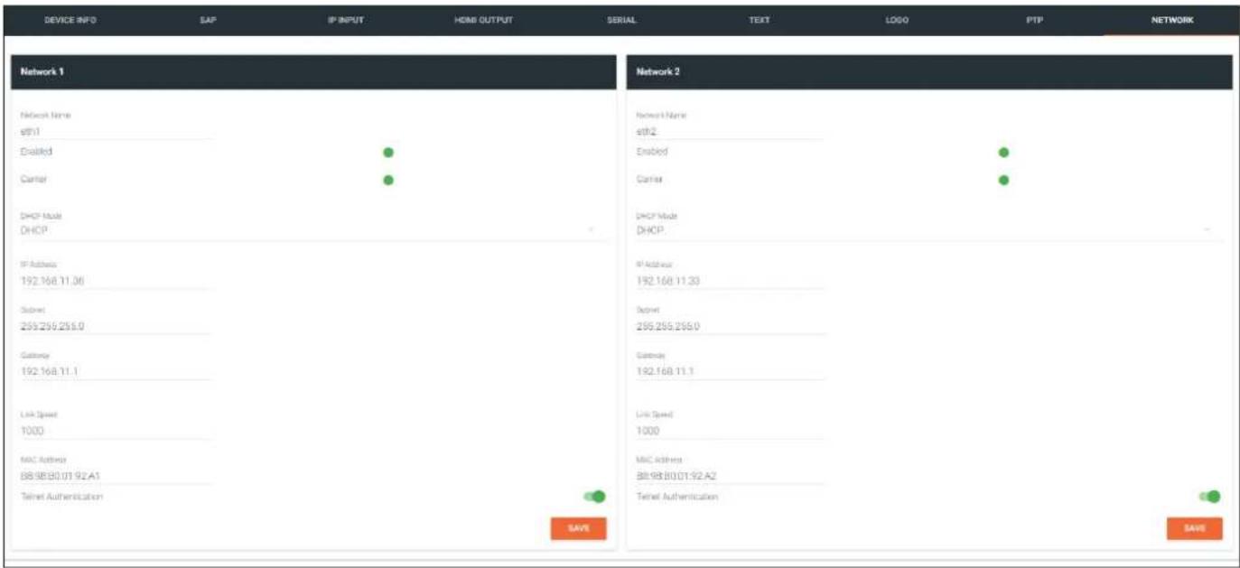
Name
The name used by AMS to identify the interface.
Enabled
This indicator displays whether or not the video stream for this channel is active. If the indicator is green, then the video stream is active.
Carrier
If this indicator is green, then an active link exists. Otherwise, this indicator will be red if no link exists.
DHCP Mode
Click this drop-down list to select the desired network mode. Select DHCP to let the DHCP server (if present) assign the decoder the IP settings; Subnet and Gateway fields will automatically be populated. When Static mode is selected, the information for the IP Address, Subnet, and Gateway fields must be entered.
IP Address
Displays the IP address used by the channel. This field can only be changed if Static mode is selected.
Subnet
Displays the subnet mask for the channel. This field can only be changed if Static mode is selected.
Gateway
Displays the gateway (router) address for the channel. This field can only be changed if Static mode is selected.
Link Speed
Displays the port speed in Mbps.
MAC Address
The MAC address of the Ethernet channel.
Telnet Authentication
Click this toggle switch to enable or disable Telnet authentication. If the toggle switch is green, then login credentials will be required at the start of a Telnet session.
The Virtual Matrix
- Click the ≡icon, in the upper-left corner of the AMS Dashboard.
- Click Virtual Matrix.
![AMS and/or partition User Product Documentation Updates ad400-1000 View AMS Documentation [New AMS Documentation] ATLONA AMS Version Notes [ ] (Active Full Version) • New https: Adjust Devices must be required settings. • Bug For: Microsoft FrontPage Application 5 Devices Added 5 Devices Connected All Devices Samr Tools Commercial 1 Users Devices Sites Equipment Virtual Matrix](/content/2026/05/964795/images/681c2f1b14355e9df662c6261960f648138331c7eb471942f0c5d982882ea8d3.jpg)
- The OmniStream Virtual Matrix page will be displayed.
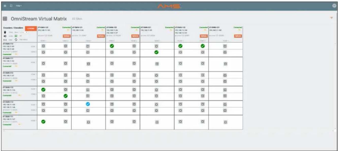
Layout and Operation
The illustration below, shows a multiple OmniStream units (encoders and decoders). The Virtual Matrix is organized into rows and columns.
The blue circle with the checkmark indicates that these two OmniStream units are connected to one another. The second column identifies a dual-channel decoder (AT-OMNI-122). The third row shows a dual-channel encoder (AT-OMNI-112). In this example, the source signal on HDMI 1 IN (encoder) is being sent out, over the network, and will be displayed on HDMI 1 on the decoder. This will create a cross-connection, which connects both the encoder and decoder together.
- Creating a cross-connection
To route an input on an encoder to an output, locate the row and column where an input and output intersect, then click the square with the dots around it.
- Removing a cross-connection
To remove a cross-connection, click on the desired circle icon with the check mark symbol. The square with the dots around it will be displayed indicating that the cross-connection has been removed.
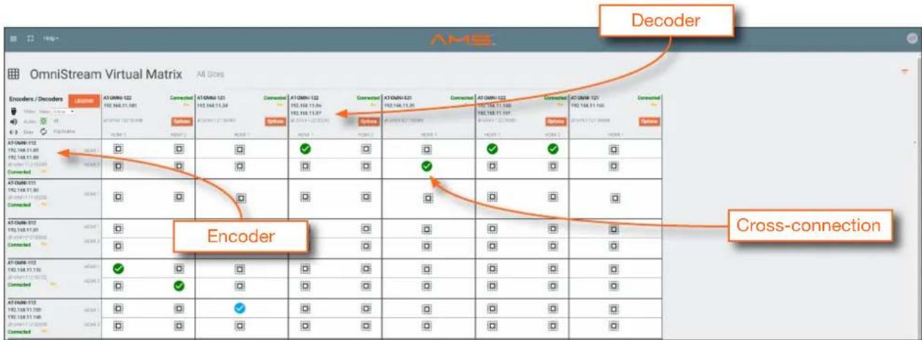
• To view the individual streams for video, audio, and data, click the icons on the upper-left corner of the screen.
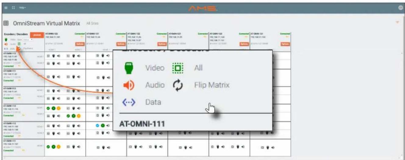
When these icons are clicked, the associated icons will be displayed in the rows and columns of the Virtual Matrix.
| Symbol Description | |
| V | Video only |
| A | Audio only |
| D | Data only |
| ✓ | Connected; not all signals are active |
| ✓ | Connected; all streams are being used |
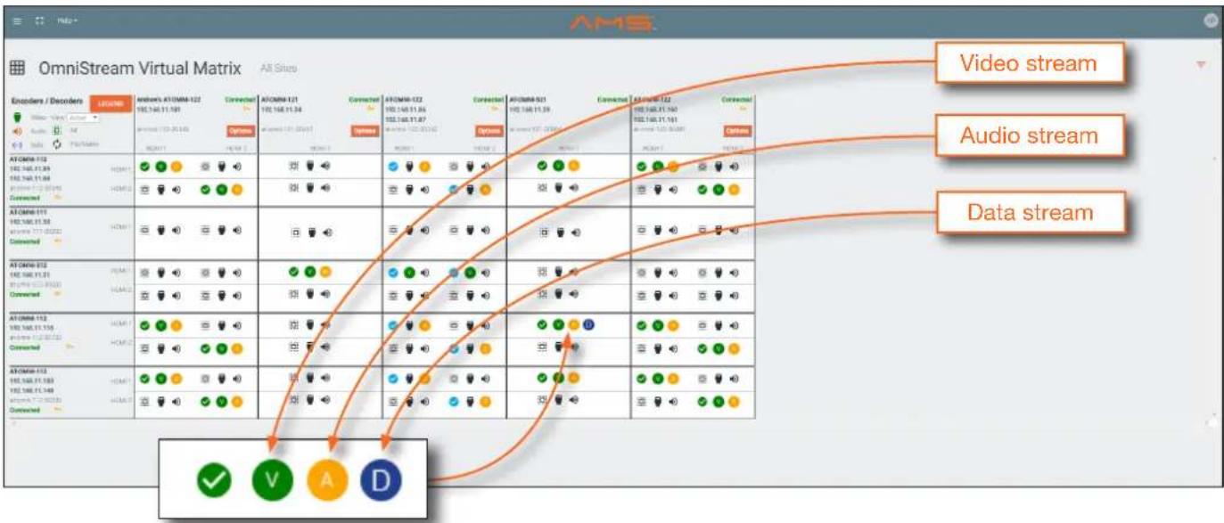

IMPORTANT: R-Type and Pro compatibility: R-Type encoders (AT-OMNI-512) and decoders (AT-OMNI-521) operate in Video Mode, only. Pro encoders can be set to either Video Mode or PC Mode. Video Mode is incompatible with PC Mode. Therefore, in order for both R-Type and Pro encoders/decoders to work within a system, Pro encoders/decoders must be set to Video Mode. Refer to Setting the Video Mode (page 43) for more information.
- Click the Video, Audio, and Data icons to return to the normal view.
- Since only HDMI (both audio and video) is being used, the V (video) and A (audio) icons are displayed. The blue circle with the checkmark indicates that the cross-section has been created. However, not all streams are being used. Refer to the chart below.
- This illustration also shows that the data stream (the icon with two arrows and three dots), which is used for control, is also being used and is displayed as a dark-blue circle with the letter "D".
- The icons in the upper-left corner can also act as a filter. This allows for a clear breakdown of where signals are being routed and is useful when several encoders and decoders are used on a network.
Appendix
Updating the Firmware
Firmware updates are managed through the Atlona Management System (AMS) software.

IMPORTANT: If updating to 1.2.1 from version 1.0, OmniStream units must first be updated to version 1.1.
- Click DEVICE INFO in the menu bar.
- Click the UPDATE FIRMWARE button to display the Firmware Update dialog.
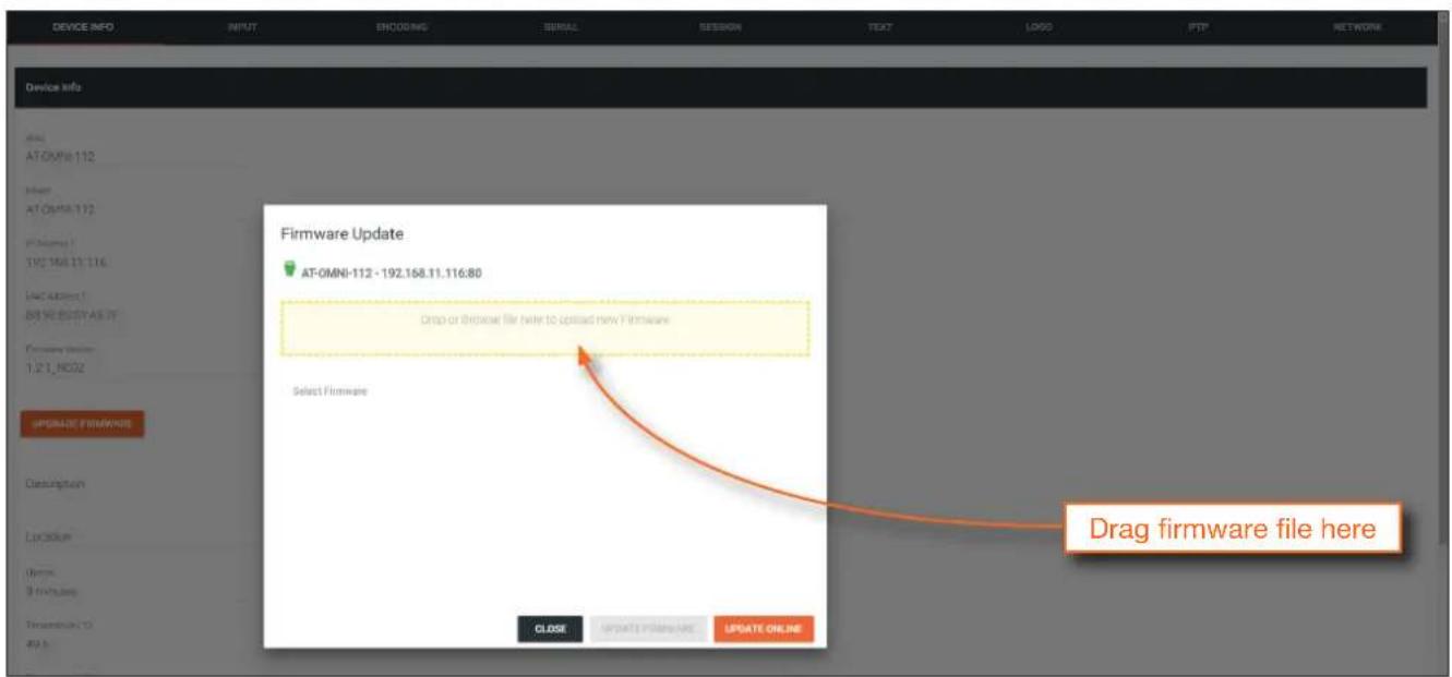
- Click and drag the firmware file to yellow box, to upload the firmware to the device. OmniStream firmware files use the .v2pup file extension. Once the firmware file has been uploaded, it will appear under the Select Firmware section of the dialog box.
- Click the UPDATE FIRMWARE button to begin the update process.
- Click and drag the firmware file to yellow box, to upload the firmware to the device. OmniStream firmware files use the .v2pup file extension. Once the firmware file has been uploaded, it will appear under the Select Firmware section of the dialog box.
- Click on the firmware file name to highlight it.
- Click the UPDATE FIRMWARE button, at the bottom of the dialog box, to begin the update process.
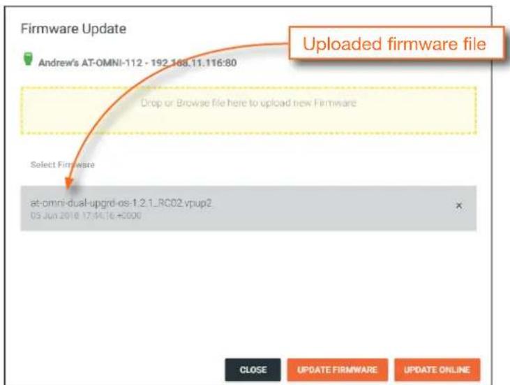
After the UPDATE FIRMWARE button is clicked, the Upgrade Firmware Started message box will be displayed.

- Click the orange up-arrow icon, in the upper-right corner of the screen, as shown below. If this icon is orange, it indicates that a firmware update is in progress.
The progress bar for the update process will be displayed. Once the file is uploaded to the encoder, the update procedure is a rapid process.
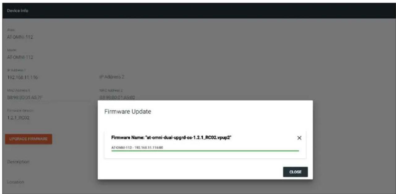
- Click the "X" to close out the progress bar window, then click the CLOSE button to dismiss the Firmware Update message box.
- The firmware update process is complete.
- Clear the web browser cache and refresh the web page. The new firmware version will appear in the Firmware Version field, in the DEVICE INFO page.
FEC Details
Matrix Size, Overhead, and Latency
- FEC can only work if a single packet from each row/column is missing. Multiple packets missing from each row/column will cause FEC to fail.
- Due to the above, a smaller matrix is more robust, as there is a better chance of errors not occurring in the same row/column.
- FEC has a bitrate overhead that is inversely proportional to the matrix size: the bigger the matrix, the less bitrate overhead is generated.
- FEC has a latency overhead that is directly proportional to the matrix size: the bigger the matrix, the more latency is introduced.
» As of v1.0.0, OmniStream does not explicitly synchronize audio and video. Therefore, FEC configuration can have a noticeable impact on lip sync. The tables below should be used to keep the audio/video lip sync as tight as possible.
- FEC latency overhead is also inversely proportional to bitrate: the higher the bitrate, the less FEC latency is introduced.
» For applications where lip sync is very critical, using a higher audio sampling rate, and thus a higher audio bitrate, can result in more accurate lip sync.
FEC and Video Bitrate
- The bitrate configured on the video encoder includes FEC overhead and will automatically adjust itself depending on the bitrate needed for FEC.
• FEC overhead can be calculated using the following formulas:
$$ \text { Video rate } = \frac {\text { Configured bit rate }}{1 + \left(\frac {\text { Rows } + \text { Columns }}{\text { Rows } \times \text { Columns }}\right)} $$
$$ F E C \text { rate } = \text { Configured bit rate } - \text { Video rate } $$
- The following table provides a few examples of how this works.
FEC / matrix usage Configured bit rate Used for video Used for FEC
| FEC disabled 900 Mbps 900 Mbps 0 Mbps | ||
| FEC enabled, 4x4 900 Mbps 600 Mbps 300 Mbps | ||
| FEC enabled, 10x10 900 Mbps 750 Mbps 150 Mbps | ||
| FEC enabled, 20x20 900 Mbps 818 Mbps 82 Mbps | ||
| FEC enabled, 4x4 450 Mbps 300 Mbps 150 Mbps | ||
| FEC enabled, 10x10 450 Mbps 375 Mbps 75 Mbps | ||
| FEC enabled, 20x20 450 Mbps 409 Mbps 41 Mbps |
FEC, Latency, and Lip Sync
- In order for FEC to work, the matrix must be filled in order to calculate the FEC packets. This introduces some additional latency. Due to high bitrates, this is not noticeable for video, but can be very significant for audio. Therefore, Atlona recommends either leaving FEC disabled for audio or using a very small matrix.
- Latency calculations are complex. The tables below provide some common working benchmarks. In order to minimize lip sync issues, try to match the additional latencies for video and audio as closely as possible.
» Video - additional video latency for enabling FEC using various matrix sizes.
| Configured bit rate 4x4 10x10 20x20 | |||
| 900 Mbps 0.64 ms 3.20 ms | 11.74 ms | ||
| 450 Mbps 1.28 ms 6.40 ms | 23.47 ms | ||
» Audio - additional audio latency for enabling FEC using various matrix sizes.
| Format 1x4 2x4 4x4 10x10 | ||||
| 2 channel PCM, 44.1 kHz | 34.01 ms | 68.03 ms | 136.10 ms | 850.30 ms |
| 2 channel PCM, 48 kHz | 31.25 ms | 62.50 ms | 125.00 ms | 781.30 ms |
| 2 channel PCM, 96 kHz | 15.63 ms | 31.25 ms | 62.50 ms | 390.60 ms |
| 2 channel PCM, 192 kHz | 7.81 ms | 15.63 ms | 31.25 ms | 195.30 ms |
- It is recommended to keep lip sync within ±1 frame of video to prevent any noticeable syncing issues.
• Examples of good choices to minimize lip sync issues are:
» Video configured for 450 Mbps, FEC 10x10; Audio is 2 channel PCM, 192 kHz, FEC 1x4: 6.40 ms – 7.81 ms = -1.41 ms
» Video configured for 900 Mbps, FEC 10x10; Audio is 2 channel PCM, 48 kHz, FEC disabled: 6.40 ms – 0 ms = 6.40 ms
Mounting Instructions
OmniStream decoders includes two mounting brackets and four mounting screws, which can be used to attach the unit to any flat surface.
- Using a small Phillips screwdriver, remove the two screws from the left side of the enclosure.
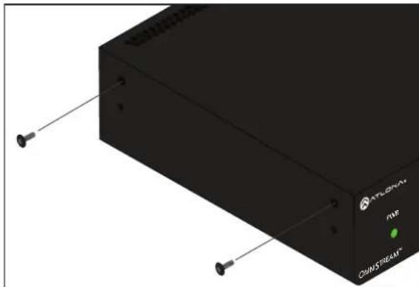
natural_image
3D rendering of a black electronic device with two pins and a power button, no visible text or symbols on the body.-
Position one of the rack ears, as shown below, aligning the holes on the side of the enclosure with one set of holes on the rack ear.
-
Use the enclosure screws to secure the rack ear to the enclosure.
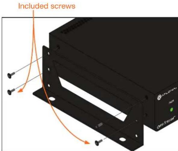
-
To provide added stability to the rack ear, use two of the included screws and attach them to the two holes, directly below the enclosure screws, as shown above.
-
Repeat steps 1 through 4 to attach the second rack ear to the opposite side of the unit.
-
Mount the unit using the oval-shaped holes, on each rack ear. If using a drywall surface, a #6 drywall screw is recommended.
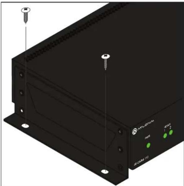
natural_image
3D rendering of a black ATLON device with screw and indicator lights, no visible text or symbols on the body or background.
NOTE: Rack ears can also be inverted to mount the unit under a table or other flat surface.
Rack Tray for OmniStream
OmniStream decoders can also be mounted in the OmniStream rack tray (AT-OMNI-1XX-RACK-1RU). The rack tray is sold separately and provides easy mounting and organization of up to two OmniStream encoders/decoders in a convenient 1U rack tray. The OmniStream rack tray can be purchased directly from Atlona.
- Position the OmniStream products, as shown in the illustration below.
- Using the included screws, secure each unit to the rack with a Philips screwdriver.

NOTE: OmniStream units can be mounted forward-facing or back-facing, depending upon your requirements.
- Install the entire assembly into an empty 1U slot in the rack.
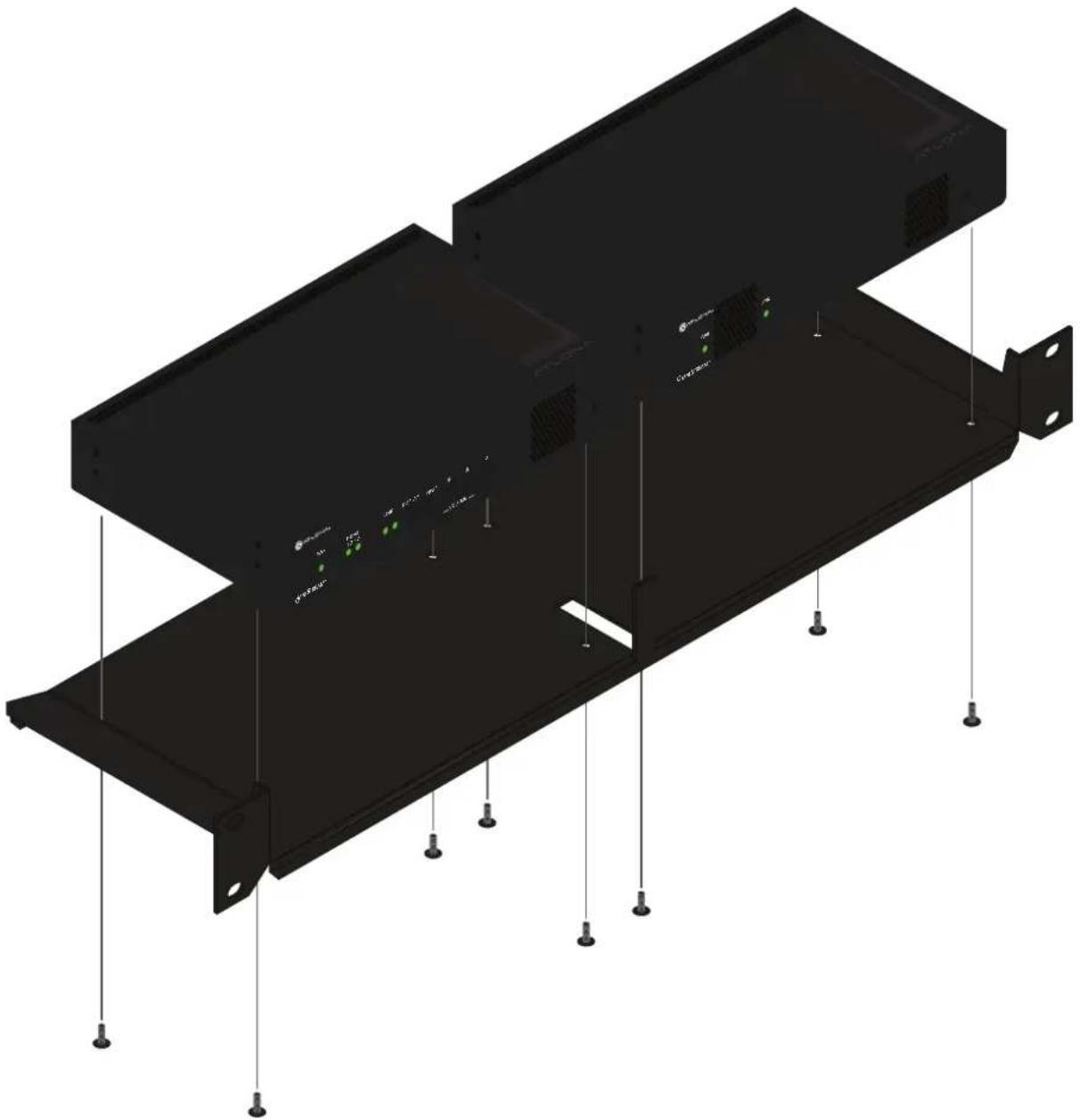
natural_image
3D technical illustration of a black server rack with mounting flanges and vertical connectors (no text or symbols)Specifications
| Video | |
| HD/SD 4096x2160@24Hz, 3840 | x2160@24/25/30Hz (UHD), 1080p@23.98/24/25/29.97/30/50/59.94/60Hz, 1080i@25/29.97/30Hz, 720p@30/50/59.94/60Hz |
| VESA* 1920x1200, 1680x1050, | 1600x1200, 1600x900, 1440x900, 1400x1050, 1366x768,1360x768, 1280x1024, 1280x800, 1280x768, 1152x768, 1024x768 |
| Color Space YUV, RGB | |
| Codec VC-2 | |
| Chroma Subsampling 4:4:4, 4:2:2 | |
| Color Depth 8-bit, 10-bit, 12-bit | |
| Scaling Yes | |
| Audio | |
| HDMI LPCM 2.0, LPCM 5.1, LPCM 7.1, Dolby® Digital, Dolby Digital Plus, Dolby TrueHD,Dolby Atmos®, DTS® 5.1, DTS-HD Master AudioTM | |
| Analog 2-channel balanced input / output | |
| Sample Rate 32 kHz, 44.1 kHz, 48 kHz, 88.2 kHz, 96 kHz, 176.4 kHz, 192 kHz | |
| Bit Rate 24-bit (max.) |
| Distance Feet Meters | ||
| Per hop of Ethernet cable | 330 | 100 |
| Signal | |
| CEC | Yes; display, volume, power, input |
| HDCP | 1.4, 2.2* |
| Scrambling | AES 128 |
* Dual-channel decoders are limited to HDCP 1.4.
| IP | |
| Protocol | RTP |
| Ethernet Speed | 10/100/1000 Mbp/s |
| Addressing | DHCP, static |
| QoS tagging | RFC 2475 |
| FEC | SMPTE 2022-5:2013; Columns: 1 to 20; Rows: 4 to 20 |
| RS-232 | |
| Baud Rate | 2400 to 115200 bp/s |
| Connector | Molex, 3-pin x 2 |
| Temperature | Fahrenheit | Celsius |
| Operating | 32 to 122 | 0 to 50 |
| Storage | -4 to 140 | -20 to 60 |
| Humidity (RH) | 20% to 90% (non-condensing) | |
* All VESA resolutions are 60p.
Appendix
| Power | ||
| Consumption ~13 W (w/o analog audio), TBD (w/ analog audio) | ||
| Supply (optional) Input: 85 V ~ | 264 V AC 50/60 HzOutput: 48 V DC, 0.83 A | |
| SKU AT-PS-48083-C | ||
| Dimensions Millimeters Inches | ||
| H x W x D 34 x 208 x 112 1.34 x 8.19 x 4.41 | ||
| Weight Kilograms Pounds | ||
| Single channel 0.7 1.50 | ||
| Dual-channel 0.7 1.54 | ||
| Certification | ||
| Power Supply CE, FCC, cULus, | RoHS, RCM | |
| Product CE, FCC, RoHS | ||

- Networked AV Decoder
- Version Information
- Welcome to Atlona!
- Sales, Marketing, and Customer Support
- Main Office
- International Headquarters
- Operating Notes
- Atlona, Inc. ("Atlona") Limited Product Warranty
- Coverage
- OR
- Coverage Periods
- Limited Product Warranty Terms – New Products
- Limited Product Warranty Terms - Refurbished (B-Stock) Products
- Remedy
- Exclusions
- Disclaimers
- Limitation on Liability
- Exclusive Remedy
- Other Conditions
- Important Safety Information
- CAUTION
- FCC Statement
- Table of Contents
- Appendix
- Introduction
- Features
- OmniStream Single-Channel Decoder
- OmniStream Dual-Channel Decoder
- Package Contents
- Panel Description
- RS-232
- AUDIO
- DC 48V
- PWR
- LINK
- REBOOT
- HDMI OUT
- ETHERNET
- LINK 1 / LINK 2
- ID
- REBOOT
- HDMI OUT 1 / HDMI OUT 2
- ETHERNET 1 / ETHERNET 2
- RS-232
- AUDIO 1 / AUDIO 2
- Installation
- RS-232 Connections
- IR Connections
- Decoder
- Encoder
- Audio Connectors
- AT-OMNI-121
- AT-OMNI-122
- Connection Instructions
- Configuration
- Discovery using AMS
- Accessing Decoders in AMS
- Configuring a Static IP Address
- Basic Operation
- LED Indicators
- Rebooting OmniStream
- ID Button
- Broadcast Messaging
- Reset to Factory-Default Settings.
- Unicast Mode
- Multicast Mode
- Configuring Audio Output
- De-embedding Audio
- Embedding Audio
- Control Using RS-232 Commands
- Triggering Stored Commands
- Using TCP Proxy
- 802.1X Authentication
- EAP-TLS Protocol
- PEAP/MSCHAPv2 Protocol
- AES67 Audio
- IR Configuration
- Serial Port 2
- Serial Configuration 2
- Bidirectional:
- Scrambling
- Standard Method
- Using the Virtual Matrix
- Setting the Video Mode
- Slate / Logo Insertion
- Deleting Slates / Logos
- Text Insertion
- Creating Video Walls
- Bezel Compensation
- Using Velocity™
- Configuring Redundant Streams
- Redundancy Grace Period
- The AMS Interface
- Device Info page
- Alias
- Model
- Model Description
- IP Address 1 / IP Address 2
- MAC Address 1 / MAC Address 2
- Firmware version
- Choose File
- UPGRADE FIRMWARE
- Description
- Location
- Uptime
- Temperature (°C)
- Temperature (°F)
- Hostname
- NTP Server
- Buttons
- LEDs
- IMPORT CONFIGURATION
- FACTORY RESET
- REBOOT
- SAP page
- Enabled
- IP Input page
- Name
- Enable
- Interface
- Multicast Address
- Mode
- Addresses
- Port
- HDMI Output page
- Output
- Key
- Encrypted
- Supported Version
- Negotiated Version
- Video
- Input
- Backup Mode
- Backup Input
- Configuration Grace Period
- Active Input
- Status
- Stretch / crop mode
- Resolution
- Slate Mode
- To Primary
- To Backup
- Audio
- Downmixing
- Enable AES67
- Mute
- Volume
- Analog Input
- Analog Output
- Aux (CEC)
- Auto On
- Projector Cooldown (s)
- Standby Timeout
- Type
- Video Optimization
- Serial page
- Serial Port
- Supported Modes
- Baud Rate
- Data
- Parity
- Stop
- Flow
- Serial Configuration
- Interface Description
- Destination IP address
- Destination UDP port
- Command
- Interpret on Description
- ASCII
- HEX
- Text page
- Text Name
- Text
- Scroll Speed
- Iterations
- Color
- Red, Green, Blue, Alpha
- Horizontal (%), Vertical (%)
- Size
- Width (%), Height (%)
- Logo page
- New Logo
- UPLOAD
- Logo
- Target
- Select Logo
- Aspect Ratio
- Horizontal
- Vertical
- Height
- Width
- PTP page
- Domain Number
- Priority 1
- Priority 2
- Is GM Present
- GM Identity
- Master Offset
- Network page
- Carrier
- DHCP Mode
- IP Address
- Subnet
- Gateway
- Link Speed
- MAC Address
- Telnet Authentication
- The Virtual Matrix
- Layout and Operation
- - Creating a cross-connection
- - Removing a cross-connection
- Updating the Firmware
- FEC Details
- Matrix Size, Overhead, and Latency
- FEC and Video Bitrate
- FEC, Latency, and Lip Sync
- Mounting Instructions
- Rack Tray for OmniStream
Brand : Atlona
Model : OMNI-122
Category : Digital decoder