AT-OMNI-521 - Digital decoder Atlona - Free user manual and instructions
Find the device manual for free AT-OMNI-521 Atlona in PDF.


| Product Type | Single-Channel Networked AV Decoder |
| Brand | Atlona |
| Model | AT-OMNI-521 |
| Dimensions (H x W x D) | 1.34 x 8.19 x 4.41 in (34 x 208 x 112 mm) |
| Weight | 1.5 lb (0.7 kg) |
| Power Supply | PoE (Power over Ethernet) or optional 48V DC power supply (sold separately) |
| Video Input | OmniStream-encoded video stream (via network) |
| Video Output | HDMI 2.0, up to 4K/UHD @ 60 Hz with HDR10, HLG, Dolby Vision |
| Audio | Embedded audio pass-through; AES67 support up to LPCM 7.1 channels |
| Control | RS-232 (via terminal block), IR pass-through, CEC, TCP Proxy |
| Compression | VCx (visually lossless) and VC-2 (SMPTE-2042) |
| Video Wall Support | Yes, up to 2x2 at 4K60, configurable with bezel compensation and rotation |
| Fast Switching | Yes, with user-configurable timeout |
| HDCP Compliance | HDCP 2.2 |
| Scrambling/Descrambling | AES-128 encryption, default key 'scrambling' |
| Management | Built-in web server (HTTP/HTTPS), Telnet, SSH, CLI |
| Network Interface | 1x Gigabit Ethernet (PoE enabled) |
| Mounting | Rack ears included; optional OmniStream rack tray (AT-OMNI-1XX-RACK-1RU) |
| Operating Temperature | 0°C to 40°C (32°F to 104°F) |
| Certifications | CE, FCC, CB, RoHS; NDAA-899 and TAA compliant |
| Repair | No user-serviceable parts; refer servicing to qualified personnel |
| Cleaning | Clean with a dry cloth only |
| Warranty | See https://atlona.com/warranty |
Frequently Asked Questions - AT-OMNI-521 Atlona
User questions about AT-OMNI-521 Atlona
0 question about this device. Answer the ones you know or ask your own.
Ask a new question about this device
Download the instructions for your Digital decoder in PDF format for free! Find your manual AT-OMNI-521 - Atlona and take your electronic device back in hand. On this page are published all the documents necessary for the use of your device. AT-OMNI-521 by Atlona.
USER MANUAL AT-OMNI-521 Atlona
Single-Channel Networked AV Decoder


ATLONA.
a PANDUIT company
Version Information
Version Release Date Notes
13 Jan 2024 Updated warranty information

ATLONA.
a PANDUIT company
Sales, Marketing, and Customer Support
Main Office
Atlona Incorporated
70 Daggett Drive
San Jose, CA 95134
United States
Office: +1.408.962.0515
Sales and Customer Service Hours
Monday - Friday: 6:00 a.m. - 4:30 p.m. (PST)
https://atlona.com/
International Headquarters
Atlona International AG
Tödistrasse 18
8002 Zürich
Switzerland
Office: +41.43.508.4321
Sales and Customer Service Hours
Monday - Friday: 09:00 - 17:00 (UTC +1)
Operating Notes

IMPORTANT: Visit http://www.atlona.com/product/AT-OMNI-521 for the latest firmware updates and User Manual.
Warranty

To view the product warranty, use the following link or QR code:
https://atlona.com/warranty/.

ATLONA.
a PANDUIT company
Important Safety Information
CAUTION
OF ELECTRIC SH DO NOT OPEN
CAUTION: TO REDUCT THE RISK OF
ELECTRIC SHOCK
DO NOT OPEN ENCLOSURE OR EXPOSE TO PAIN OR MOISTURE
NO UGER-SERVICEABLE PARTS
INSIDE REFER SERVICING TO
QUALIFIED SERVICE PERSONNEL

The excision point within an equilateral triangle is intended to alert the user to the presence of important operating and maintenance instructions in the literature accompanying the product.

The information bubble is intended to alert the user to helpful or optional operational instructions in the literature accompanying the product.
- Read these instructions.
- Keep these instructions.
- Heed all warnings.
- Follow all instructions.
- Do not use this product near water.
- Clean only with a dry cloth.
- Do not block any ventilation openings. Install in accordance with the manufacturer's instructions.
-
Do not install or place this product near any heat sources such as radiators, heat registers, stoves, or other apparatus (including amplifiers) that produce heat.
-
Do not defeat the safety purpose of a polarized or grounding-type plug. A polarized plug has two blades with one wider than the other. A grounding type plug has two blades and a third grounding prong. The wide blade or the third prong are provided for your safety. If the provided plug does not fit into your outlet, consult an electrician for replacement of the obsolete outlet.
-
Protect the power cord from being walked on or pinched particularly at plugs, convenience receptacles, and the point where they exit from the product.
-
Only use attachments/accessories specified by Atlona.
-
To reduce the risk of electric shock and/or damage to this product, never handle or touch this unit or power cord if your hands are wet or damp. Do not expose this product to rain or moisture.
-
Unplug this product during lightning storms or when unused for long periods of time.
-
Refer all servicing to qualified service personnel. Servicing is required when the product has been damaged in any way, such as power-supply cord or plug is damaged, liquid has been spilled or objects have fallen into the product, the product has been exposed to rain or moisture, does not operate normally, or has been dropped.


ATLONA.
a PANDUIT company
Table of Contents
| Introduction | 7 |
| Features | 7 |
| Package Contents 7 | |
| Introduction to OmniStream 8 | |
| OmniStream 101 8 | |
| IP Address Assignment 8 | |
| Network Bandwidth and OmniStream Compression 9 | |
| Streams | 9 |
| Sessions | 9 |
| Subscribing to a Stream 10 | |
| OmniStream Naming Schema 11 | |
Panel Description 12
| Installation | 13 |
| RS-232 Connections 13 | |
| IR Connections 14 | |
| Connection Instructions 15 | |
| Connection Diagram 16 |
Getting Started 17
| ID Button 17 | |
| Broadcast Messaging | 17 |
| Rebooting OmniStream | 17 |
| Resetting to Factory-Defaults | 18 |
| Using the ID button | 18 |
| Using the Mclear command | 18 |
| Using the Web Server | 18 |
| LED Indicators | 19 |
| Accessing the Web Server | 20 |
| Configuration Tutorial | 21 |
| Physical Connections | 21 |
| Setting the Custom Mode | 22 |

ATLONA.
a PANDUIT company
Table of Contents
Device Operation 35
Device Control 35
Downstream Control using RS-232 35
Control using TCP Proxy 38
Downstream Control using Triggering 40
Upstream Control using RS-232 45
Upstream Control using IR 47
Fast Switching 48
Fast Switching FAQs 49
AES67 Audio 50
Descrambling
Slate / Logo Insertion 54
Adding Slates / Logos 54
Deleting Slates 55
Deleting Logos 55
Text Insertion
Configuring a Static IP Address
Creating Video Walls 58
Introduction
Landscape Mode
Portrait Mode
Bezel Compensation
Configuration and Management Interfaces
Web Server
System information page
SAP Listener page
IP Input page
Serial page
HDMI Output page
Logo page
Text page
Network page
53
56
57
58
59
63
68
69
69
72
73
74
76
81
83
85

ATLONA.
a PANDUIT company
Introduction
The Atlona OmniStream™ 521 (AT-OMNI-521) is a networked AV decoder for an OmniStream-encoded video stream up to UHD @ 60 Hz and HDR, plus embedded audio and RS-232 or IR control pass-through. It is part of the OmniStream R-Type Series, designed for high performance, flexible distribution of AV over Gigabit Ethernet in residential and commercial applications. The OmniStream 521 is HDCP 2.2 compliant and ideal for the latest as well as emerging UHD and HDR displays. It features visually lossless compression, optimized for motion video, pristine-quality imaging, and extremely low, sub-frame latency from encode to decode – critical for demanding applications such as gaming. This decoder includes an HDMI output, high performance upscaling and downscaling, aspect ratio control, and video wall processing, plus presentation enhancement features such as logo insertion and scrolling on-screen text
Features
- AV decoder for HDMI® up to 4K/UHD, plus embedded audio and RS-232 or IR control pass-through
• Supports UHD @ 60 Hz plus HDR formats
• High performance, visually lossless video compression - Pristine-quality downscaling and upscaling
- Simplify integration with plug-and-play network switch compatibility
- Remotely powered via PoE (Power over Ethernet)
• Video wall processing
• Enhance AV presentations with visual enhancements
Package Contents
1 x AT-OMNI-521

ATLONA.
a PANDUIT company
Introduction to OmniStream
OmniStream 101
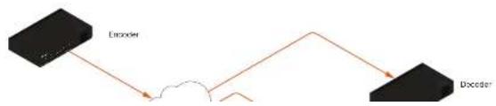
OmniStream products are similar in principle to matrix switch endpoints: A/V signals are sent from one point (transmitter) to another point (receiver) over category cable. However, OmniStream stands apart from matrix switchers, in that it is an IP-based solution, allowing this data to be sent over a standard IP network. In addition, these endpoints are referred to as encoders and decoders. Encoders act as "transmitters" and decoders act as "receivers".

DEFINITIONS
Encoder - Compresses source signals before sending them out over a network environment.
Decoder – Receives and decompresses signals from an encoder and sends them to an output device, such as a display or other sink device.
IP Address - A unique numerical label that is assigned to each device connected to a network.
IP Address Assignment
Figure 1.1 below, shows an encoder and a decoder, connected through a network switch. As with all network devices, both the encoder and decoder must have unique IP addresses. OmniStream encoders and decoders are DHCP-enabled, by default. This means that when the encoder/decoder is connected to the network, and a DHCP server is available, the encoder/decoder will automatically be assigned an IP address. If no DHCP server is available, then the unit will use a self-assigned IP address within the range of 169.254.xxx.xxx/16. OmniStream devices can also be assigned a static IP address, if necessary. Static IP addressing will be covered in a later section.
Figure 1.1 - An encoder and decoder on a network, with assigned IP addresses.


ATLONA.
a PANDUIT company
Introduction to OmniStream
Network Bandwidth and OmniStream Compression
When sending video and audio over a network, the available bandwidth needs to be managed. Gigabit Ethernet switches are very common and can take advantage of installed Category 5e cable. 10-Gigabit Ethernet switches are available, but are more expensive per port and require Category 6A cable or better. The chart below shows uncompressed data rates for common resolutions. These data rates exceed the available bandwidth of Gigabit Ethernet, but using the compression technology in OmniStream, this video can be streamed over cost-effective Gigabit networks.
Resolution Data Rate*
| 1920 x 1080p 30 Hz 2.2 Gbps |
| 1920 x 1080p 60 Hz 4.5 Gbps |
| 3840 x 2160p 30 Hz 8.9 Gbps |
| 3840 x 2160p 60 Hz 17.8 Gbps |
* Data rate is shown without compression.
OmniStream compresses the source data at the encoder, before it is sent out over the network. This process is known as encoding. OmniStream uses VCx and VC-2 compression, which are intermediate compression schemes and offer lower latency and higher video fidelity than an interframe compression scheme, such as H.264 or H.265. Interframe codecs are typically used by cable or internet providers and use very aggressive bit rates (low bandwidth) with high latency (delay), which results in lag. VCx and VC-2 provide both high quality (high bit rates) and very low-latency for a much more desirable viewing experience.
Streams
The term stream is used throughout this manual, to describe the different types of signals that are transmitted over a network. For example, if a blu-ray player is connected to an encoder, both video and audio are sent to the encoder over an HDMI cable. The term video stream is used to identify the video portion of a signal and audio stream identifies the audio portion of the signal.

ATLONA.
a PANDUIT company
Introduction to OmniStream
Subscribing to a Stream
To receive information from an encoder, the decoder must subscribe to the multicast IP address and UDP port of the stream(s). Note that the decoder does not subscribe to the session, but to the stream(s) within the session. The process of subscribing is similar to changing the channel on a Set-Top Box. For example, in order to view the content on channel 213, the Set-Top Box must be set to channel 213. Similarly, for a decoder to subscribe to an encoder stream, the multicast IP address and UDP port settings on the decoder must be set to the same values as the encoder to which it is subscribed. Note that the management IP address of a unit is different than its multicast IP address.
Figure 1.2 - Diagram of a video and audio stream, transmitted over an Ethernet cable, to the subscribing decoder.

flowchart
graph LR
    A["Encoder"] --> B["Video\nDestination Multicast/Unicast Address\n376.0.0.1\nDestination UDP Port\n1000"]
    A --> C["Audio\nDestination Multicast/Unicast Address\n226.0.10.1\nDestination UDP Port\n1000"]
    D["Ethernet"] --> E["Video Stream Multicast IP: 226.0.0.1\nAudio Stream\nMulticast IP: 226.0.10.1\nUDP Port: 1000\nUDP Port: 1000"]
    D --> F["Decoder"]
    F --> G["Video\nSubscribed Multicast Address\n376.0.0.1\nPort\n1000"]
    F --> H["Audio\nSubscribed Multicast Address\n226.0.10.1\nPort\n1000"]
Figure 1.3 shows two encoders and a single decoder connected to a network switch. Decoder "C" is subscribed to encoder "A", since the multicast IP addresses and UDP port numbers for both video and audio are set to the same values as encoder "A".
Figure 1.3 - Decoder "C" subscribed to encoder "A".

Encoder IP Address: 192.168.1.96
Multicast IP Address (Video): 226.0.0.2

ATLONA.
a PANDUIT company
Introduction to OmniStream

DEFINITIONS
Stream – Describes the video, audio, or any data that is transmitted from an encoder over the network.
Multicast IP Address - A class-D IP address assigned to a stream.
UDP Port – User Datagram Protocol (UDP) port. Part of the network addressing scheme to send and receive data to the proper destination on a network.
Subscribing – The process of selecting the multicast IP address to "listen to", in order to receive one or more encoder streams at the decoder endpoint.
OmniStream Naming Schema
Each OmniStream model has a different set of inputs and outputs and, depending upon the number of inputs and outputs. The number of supported session will depend upon the encoder model.
| Encoders Description | |
| AT-OMNI-111AT-OMNI-111-WP | One HDMI inputOne Ethernet outputSupports up to six sessions |
| AT-OMNI-112 • Two HDMI inputsTwo Ethernet outputsSupports up to six sessions | |
| AT-OMNI-512 • One HDMI inputOne Ethernet outputSupports up to four sessions | |

ATLONA.
a PANDUIT company
Panel Description

Front
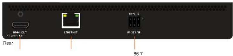
1 PWR
This LED indicator is green when the unit is powered and booted.
2 LINK
This LED indicator is green when the link integrity between the decoder and the network switch is good.
4 Reboot button
Press this button, using a small, pointed object to reboot the unit.
5 HDMI OUT
Connect an HDMI cable from this port to a UHD/HD display.

ATLONA
a PANDUIT company
Installation
RS-232 Connections
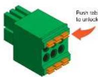
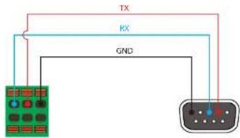
The AT-OMNI-521 provides RS-232 over IP which allows communication between an automation system and an RS-232 device. This step is optional. Either the top three or bottom three set of terminals can be used for RS-232.
- Use wire strippers to remove a portion of the cable jacket.
- Remove at least 3/16" (5 mm) from the insulation of the RX, TX, and GND wires.
- Insert the TX, RX, and GND wires into correct terminal on the included push-spring block. If using non-tinned stranded wire, press the orange tab, above the terminal, while inserting the exposed wire. Repeat this step for the TX, RX, and GND connections.
flowchart
graph TD
    A["Terminal Block 1"] -->|TX| B["Terminal Block 2"]
    A -->|RX| C["Terminal Block 3"]
    A -->|GND| D["Terminal Block 4"]
    B -->|TX| E["Terminal Block 5"]
    B -->|RX| F["Terminal Block 6"]
    B -->|GND| G["Terminal Block 7"]

NOTE: Typical DB9 connectors use pin 2 for TX, pin 3 for RX, and pin 5 for ground. On some devices, pins 2 and 3 are reversed.

ATLONA.
a PANDUIT company
Installation
IR Connections
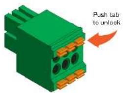
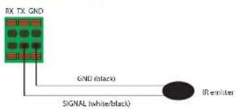
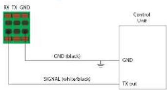
The same port that provides RS-232 connections also supports bidirectional IR pass-through, allowing a device to be controlled from either the headend or the decoder endpoint. This step is optional. Refer to Device Control (page 35) for more information.
IR emitter configuration
IR extender configuration

ATLONA.
a PANDUIT company
Installation
Connection Instructions
- Connect an Ethernet cable from the ETHERNET port on the decoder to a PoE-capable switch on the Local Area Network (LAN).

IMPORTANT: If a PoE-capable switch is not available, a PoE injector (purchased separately) must be used.
- Connect an HDMI cable from the HDMI OUT port to a UHD/HD display.
-
RS-232 (optional)
-
Connect the RS-232 controller/automation system to the RS-232 port on the decoder.
-
Connect the RS-232 device to the RS-232 port on the decoder.
-
IR (optional)
- IR emitter
Connect the IR emitter to the TX and GND pins of the RS-232 2 port. The IR emitter must be placed no more than one inch from the IR sensor on the device, in order to function properly.
- IR extender
Connect the IR extender from the RX and GND pins of the RS-232 2 port to the associated pins on the control system.
- Once the unit is powered, the PWR indicator, on the front panel, will turn red, then amber, then green.

ATLONA.
a PANDUIT company
Installation
Connection Diagram
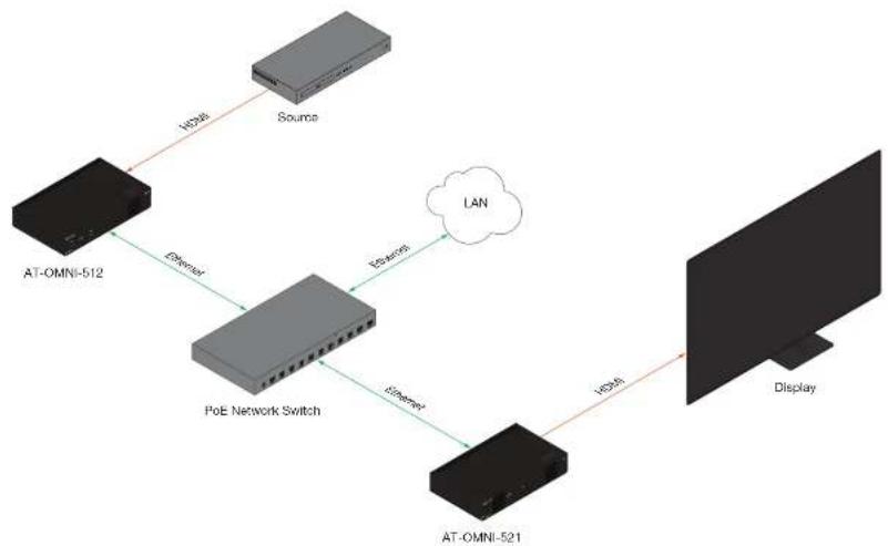
flowchart
graph TD
    A["AT-OMNI-512"] -->|HD48| B["Source"]
    A -->|Ethernet| C["PoE Network Switch"]
    C -->|Ethernet| D["LAN"]
    C -->|Ethernet| E["AT-OMNI-521"]
    E -->|HD48| F["Display"]

ATLONA.
a PANDUIT company
Getting Started
ID Button
The ID button serves two functions:
- Sends a broadcast message, over the network, to any devices that may be listening.
- Resets the decoder to factory-default settings.

NOTE: Some older hardware revisions do not have an ID button.

Broadcast Messaging
Press and release the ID button to send a broadcast notification over the network to any devices that may be listening.

ATLONA.
a PANDUIT company
Getting Started
Resetting to Factory-Defaults

WARNING: Performing a factory-default reset will erase all user-programmed settings from the encoder. IP settings are not preserved.
Using the ID button
- Press and hold the ID button for approximately 30 seconds.
- The LED indicators on the front panel will flash, then turn "off."
- The encoder is now reset and will need to be reconfigured.
Using the Mclear command
- Connect a PC to serial port 1 using a USB to serial cable.
- Set the PC console port to the following settings: 9600 baud, 8 data bits, 1 stop bit, no parity.
- Once connected to the CLI, execute the Xclear command.
Using the Web Server
- Log in to the decoder using the built-in web server. Refer to Accessing the Web Server (page 20) for more information.
- Click the FACTORY RESET button.

ATLONA.
a PANDUIT company
Getting Started
LED Indicators
The following table provides a listing of front-panel LED indicators and their status:
| LED Description | ||
| PWR Off • If | using a PoE switch,make | sure that the port on the switch that is connected to the decoder, has PoE enabled. When the decoder is powered using PoE, thePWRindicator will be green.Check the Ethernet cable for possible damage or loose connections.Connect the optional 48V DC power supply (available from atlona.com) to the encoder. When using an external power supply, thePWRindicator will be green. |
| Red • The decoder ● booting. | ||
| Amber • The decoder is booting and/or attempting to locate a DHCP server. | ||
| Green • The decoder is ready. | ||
| LINK 1 / 2 Red | • The optional 48V DC power supply is connected, but no Ethernet cables are connected between the switch and theETHERNETport(s).Check the Ethernet cable for possible damage or loose connections. | |
| Amber • The decoder is booting. | ||

ATLONA.
a PANDUIT company
Getting Started
Accessing the Web Server
In order to access the web server of the desired encoder/decoder, the IP address of the encoder must be known. This can be accomplished by using any of the following methods: 1) Running IP scanner software or 2) accessing the encoder using the domain name. When running an IP scanner, both the computer and the OmniStream encoders/decoders must be connected to the same network.

TIP: Ationa recommends downloading and using the Network Assignment Planner, when setting up OmniStream products on the network. Recording this information in this document will provide a "snapshot" of the current OmniStream network configuration. The Network Assignment Planner is available for download on the OmniStream product pages, under the Resources tab.
- Launch the desired web browser and enter the IP address or domain name of the encoder in the address bar.
- Enter the username and password. Note that the password field will always be masked. The default credentials are:
Username: admin
Password: Atlona
Username
admin
Password
●●●●●●
ATLONA
m = 311
Figure 10

ATLONA.
a PANDUIT company
Basic Configuration Tutorial
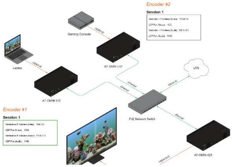
This section provides a tutorial on configuring two AT-OMNI-512 dual-channel encoders and one AT-OMNI-521 single-channel decoder. Make sure the encoders are connected to a source device and that the decoder is connected to a display. Both encoders and the decoder should be connected to the same local network. Refer to Connection Instructions (page 15) for more information.
Physical Connections
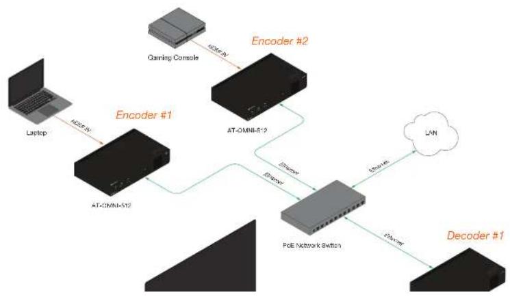
flowchart
graph TD
    A["Laptop"] -->|AT-OMNI-512| B["Encoder #1"]
    B --> C["AT-OMNI-512"]
    C --> D["Encoder #2"]
    D --> E["PoE Network Switch"]
    E --> F["Decoder #1"]
    G["Gaming Console"] -->|AT-OMNI-512| D
    H["LAN"] -->|PoE Network Switch| E
    I["Encoder #2"] -->|AT-OMNI-512| E
    J["Decoder #1"] -->|PoE Network Switch| E

ATLONA.
a PANDUIT company
Basic Configuration Tutorial
Setting the System Mode
OmniStream offers three system modes. These modes will optimize the video, based on the type of information that is being displayed and/or the desired features.
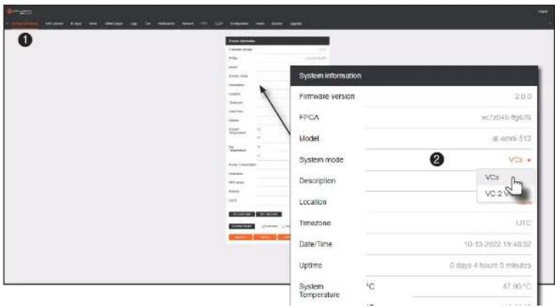
- Login to the encoder and click System Information in the menu bar.
- Click the System mode drop-down list and select VCx. This mode will provide access to all of OmniStream 2.0 features.

ATLONA.
a PANDUIT company
Basic Configuration Tutorial
Configuring Inputs
The Input page is used to verify that the encoder recognizes the source device. This page is also used to set the EDID, HDCP version, and provides detailed information about the source signal. The following procedure should be performed on both AT-OMNI-512 encoders.
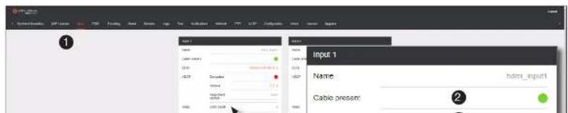
- Click Input in the menu bar.
- Since a source has been connected to the HDMI IN port, the Cable present indicator within the Input 1 window group is green, as shown below. This indicates that an active source is connected to the HDMI port.
If these indicators are red, check that each source is connected to an HDMI IN port. A red indicator may also describe faulty HDMI cables. If the sources are connected, then try different HDMI cables. If the HDMI cable integrity has been verified, then make sure that the output resolution of the source is at least 720p.

TIP: If no signal is being received on the encoder, then it's always a good practice to check the Input screen on the encoder when performing additional troubleshooting.
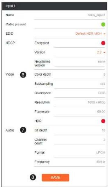
- Click the EDID drop-down list to select an EDID. For now, leave this setting at Default HCR MCR. This EDID provides general compatibility with most displays.

ATLONA.
a PANDUIT company
Basic Configuration Tutorial
- The Video section provides information about the input signal: color depth, subsampling, color space, resolution, frame rate, and HDR (High Dynamic Range). If the HDR indicator is green, this will indicate that HDR content is being transmitted from the source device.
- The Audio section displays audio information (if present) from the source device: bit depth, the number of audio channels, the audio format, and the frequency.
- Click SAVE to commit all changes.

ATLONA.
a PANDUIT company
Basic Configuration Tutorial
Encoder Settings
The Encoding page is used to assign an input to an encoder. In addition, this page allows video settings, such as bit depth, and slate/logo settings. Video thumbnails of the source device can also be displayed on this page. The following procedure should be performed on both AT-OMNI-512 encoders.
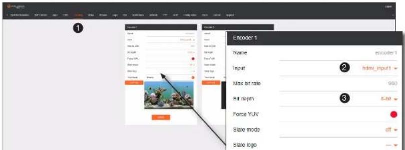
- Click Encoding in the menu bar.
- Under the Encoder 1 window group, click the Input drop-down list and select hdm input1.
- Click the Bit depth drop-down list to change the bit depth. In this example, it will be set to 8-bit.
- Click the Thumbnail > Enable toggle switch to enable it and display a thumbnail of the source. When enabled, the toggle switch is orange and a thumbnail of the source will be displayed. If no thumbnail is displayed when this feature is enabled, verify that the source is connected, powered, and is configured correctly under the Input menu.

ATLONA.
a PANDUIT company
Basic Configuration Tutorial
Creating a Session
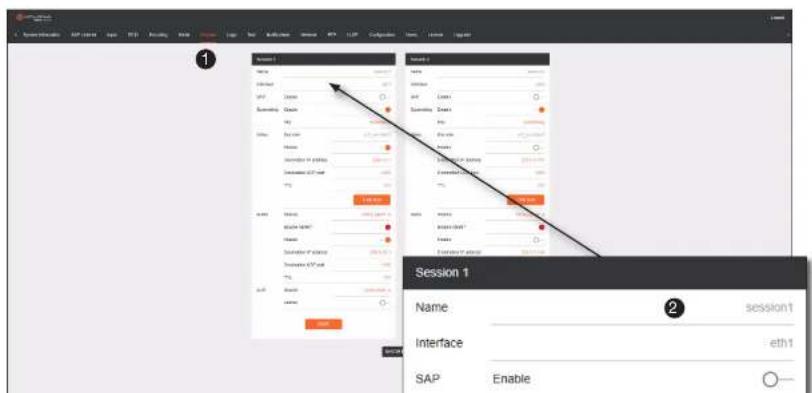
Before the video and audio (if any) can be sent out over the network, a session must be created on the encoder. The session assigns each stream to a unique multicast IP address and UDP port assignment. Sessions are always created on encoders. The following procedure should be performed on both AT-OMNI-512 encoders, except where noted.
- Click Session in the menu bar.
- Under Session 1, the Name field indicates the session name. This value is set to session1 and cannot be changed.

ATLONA.
a PANDUIT company
Basic Configuration Tutorial
Table 2.1 - Recommended multicast IP address for video, audio, and data streams.
| Stream Video Audio Data (Control) | ||||
| First source | 226.0.0.1 | 226.0.10.1 | 226.0.20.1 | |
| Second source | 226.0.0.2 | 226.0.10.2 | 226.0.20.2 | |
| nth source | 226.0.0.n | 226.0.10.n | 226.0.20.n | |
Table 2.2 - Recommended UDP ports for video, audio, and data streams.
| Stream Video Audio Data (Control) | |||
| UDP Port | 1000 1100 1200 | ||
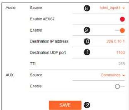
- Click the Audio > Source drop-down list and select the HDMI audio input for the session. The source is connected to HDMI IN. Therefore, set this to hdi Input1 for Session 1.
- Click the Audio > Enable toggle switch and make sure it is enabled. When enabled, it will be orange. If disabled, no audio will be streamed from the encoder.
- Enter the multicast IP address for the audio stream in the Destination IP address field. Refer to Table 2.1, above. In this example, enter 226.0.10.1 for Session 1 on Encoder #1 and 226.0.10.2 for Session 1 on Encoder #2.
11 Enter the audio stream UDP port in the

ATLONA.
a PANDUIT company
Basic Configuration Tutorial
Subscribing to an Encoder
The next step is to configure the decoder so that it is able to receive video, audio, and/or data (control) streams from the encoder. This process is referred to as "subscribing to the encoder".
Video Configuration
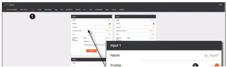
- Go to the decoder and click IP Input in the menu bar.
- Locate the Input 1 window group and verify that the Enable toggle switch is enabled. When enabled, the toggle switch will be orange. Perform the same procedure for the Input 2 window group.
- Under the Input 1 window group, enter 226.0.0.1 in the Multicast address field. Under the Input 2 window group, enter 226.0.0.2 in this field. These multicast IP address are the same addresses that were specified under the Video > Destination IP address field for the encoders.
- In the Port field, enter 1000 under both Input 1 and Input 2 window groups. These are the same port settings that were entered under the Video > UDP Port section of the encoder.
- Click the SAVE button, under the Input 1 and Input 2 window groups, to commit changes.

ATLONA.
a PANDUIT company
Basic Configuration Tutorial
Audio Configuration
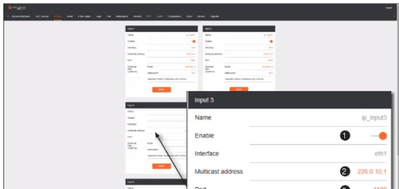
- Locate the Input 3 window group and verify that the Enable toggle switch is enabled. When enabled, the toggle switch will be orange. Perform the same procedure for the Input 4 window group.
- Under the Input 3 window group, enter 226.0.18.1 in the Multicast address field. Under the Input 4 window group, enter 226.0.18.2 in this field. These multicast IP address are the same addresses that were specified under the Audio > Destination IP address field for the encoders.
- In the Port field, enter 1100 under both Input 3 and Input 4 window groups. These are the same port settings that were entered under the Audio > UDP Port section of the encoder.
- Click the SAVE button, under the Input 3 and Input 4 window groups to commit changes.

ATLONA
a PANDUIT company
Basic Configuration Tutorial
Configuring the HDMI Output Stream
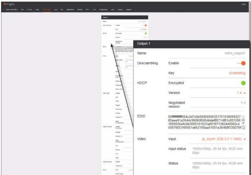
- Click HDMI Output in the menu bar.
- The Descrambling > Enable toggle switch is enabled by default. When enabled, this toggle will be orange. For this example, leave the setting enabled.
- The Descrambling > Key field is set to scrambling by default. This is the same key that is being used under the Scrambling > Key field on the encoder, and will allow the decoder to descramble the signal and send it out over the HDMI output to the display. Leave this key at its default setting.
- Click the HDCP > Version drop-down list and select the HDCP version. 2.2 will work with most sources. However, in this case, an older sink/monitor which doesn't support HDCP 2.2 is being used. Therefore, the value is set to 1.4.
- Click the Video > Input drop-down list and select the video source. Based on what has been configured, the following options are available:
| Video > Input | |
| ip_input1 | (226.0,0.1:1000) |
| ip_input2 | (226.0,0.2:1000) |
| ip_input3 | (226.0,10.1:1100) |
| ip_input4 | (226.0,10.2:1100) |
Since this is the Video field, a video source should be selected. Referring to Table 2.3, on the previous page, ip_input1 (226.0.0.1:1000) and ip_input2 (226.0.0.2:1000) are video data, from two different encoders. For this example, this field will be set to ip_input1 (226.0.0.1:1000).


ATLONA.
a PANDUIT company
Basic Configuration Tutorial
- Scroll down to the Audio > Input field and select the desired audio stream. Referring to Table 2.3 (shown below), the audio stream that is associated with encoder 1 is Input 3. Therefore, ip_input3 (226.0.10.1:1100) is selected.
Table 2.3 - Video and Audio information for each encoder.
Encoder #1 Encoder #2
| Input Multicast Address / Port |
| Input 1 Video (226.0.0.1:1000) |
| Input 3 Audio (226.0.10.1:1100) |
| Input Multicast Address / Port |
| Input 2 Video (226.0.0.2:1000) |
| Input 4 Audio (226.0.10.2:1100) |
- Click the SAVE button to commit changes.


ATLONA.
a PANQUIT company
Basic Configuration Tutorial
Figure 3.1 - Basic OmniStream setup with Decoder #1 subscribed to Encoder #1.
flowchart
graph TD
    A["Laptop"] -->|N200.0k| B["AT-CMNI-512"]
    B --> C["PCoE Network Switch"]
    C --> D["AT-OMNI-521"]
    D --> E["Podcast"]
    E --> F["Router"]
    F --> G["LAN"]
    H["Gaming Console"] --> I["AT-OMNI-512"]
    I --> J["Router"]
    J --> K["Router"]
    L["Encoder #1 Session 1"] --> M["Destination: IP Backbone (Audio): 296.0.1"]
    L --> N["UDP Port (Audio): 1000"]
    L --> O["Destination: IP Backbone (Audio): 338.0.1"]
    L --> P["UDP Port (Audio): 1100"]

ATLONA.
a PANDUIT company
Basic Configuration Tutorial
Troubleshooting
If no video and/or audio is present on the display, check the following for both Encoder #1 and Encoder #2, unless otherwise noted.
Encoder Checklist
- Verify that all encoders and decoders are set to the same system mode. In this tutorial, both encoders and the decoder should be set to vcx. Refer to Setting the System Mode (page 22).
- Go to the Input menu and make sure that the Cable present indicator, under the Input 1 window group, is green. Refer to Configuring Inputs (page 23) for more information.
- Go to the Encoding menu and verify the following under the Encoder 1 window group. Refer to Encoder Settings (page 25) for more information.
» Make sure the Input drop-down list is assigned to an input. In this tutorial, the Input field, under the Encoder 1 window group, is set to hdmInput1.
» Verify that a Thumbnail > Enable toggle switch is enabled and a thumbnail of the source is displayed.
- Go to the Session menu and verify the following under the Session window groups. Refer to Creating a Session (page 26) for more information.
» Check that the Scrambling > Enable toggle switch is enabled. Also check that the Scrambling > Key field, for this example, is set to scrambling.
» Verify that the Video > Enable toggle switch is set to enabled.
» Check the Video > Destination IP address field is set to the correct multicast IP address. In the example, 226.0.0.1. is used on Encoder #1 and 226.0.0.2 is used on Encoder #2.
» Check that the Video > Destination UDP port field is set to 1000.
» Make sure the Audio > Source is set to hdmi_input1.
» Verify that the Audio > Enable toggle switch is enabled.

ATLONA.
a PANDUIT company
Basic Configuration Tutorial
Decoder Checklist
- Verify that all encoders and decoders are set to the same system mode. In this tutorial, both encoders and the decoder should be set to vcx. Refer to Setting the System Mode (page 22).
- Go to the IP Input menu and verify the following. Refer to Subscribing to an Encoder (page 28) for more information.
» Under both the Input 1 and Input 2 window groups, verify that the Enable toggle switch is enabled.
» Check that the Multicast address field is set to the correct multicast IP address. In this example, 226.0.0.1 for Input 1 and 226.0.0.2 for Input 2.
» Check that the Port field is set to the proper port. In this example, 1000 for both Input 1 and Input 2.
» Under both the Input 3 and Input 4 windows groups, verify that the Enable toggle switch is enabled.
» Check that the Multicast address field is set to the correct multicast IP address. In this example, 226.0.10.1 for Input 3 and 226.0.10.2 for Input 4.
» Check that the Port field is set to 1100 for both Input 3 and Input 4.
- Go to the HDMI Output menu and verify the following. Refer to Subscribing to an Encoder (page 28) for more information.
» Make sure that the Descrambling > Enable toggle switch is enabled.
» Verify that the Descrambling > Key field is set to scrambling.
» Check the HDCP > Version field to make sure the correct version is selected. Also note the color of the HDCP > Encrypted indicator. if it is red, then a picture may not be displayed and result in a "blue screen" on the display. Change the HDCP > Version field, if necessary.

IMPORTANT: The scrambling key on a decoder must be identical to the scrambling key on the encoder which is being subscribed. Scrambling keys are case-sensitive.

ATLONA.
a PANDUIT company
Device Operation
Device Control
Downstream Control using RS-232
Control using RS-232 is converted and transmitted over IP by the encoder. Destination devices can either be the IP address of a display or a decoder.
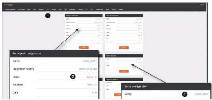
- Login to the encoder and click the Serial menu.
- Under the Serial Port Configuration window group, click the Mode drop-down list and select serial.
- Click the SAVE button.

ATLONA
a PANDUIT company
Device Operation
- Click the Session menu.
- Under the desired Session, locate the AUX section and click the Source drop-down list to select the desired serial port.
- Click the Enable toggle switch to display the additional fields.
- Enter the destination IP address and UDP port in the Destination IP address and Destination UDP port fields, respectively.


ATLONA.
a PANDUIT company
Device Operation
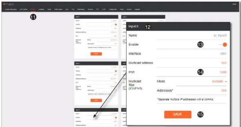
- Login to the decoder and click the IP Input menu.
- Locate an Input that does not contain a defined Multicast address field. In this example, Input 5 will be used. Note that if a multicast address was used in Step 9, then that multicast address must be entered in the Multicast address field under Input 5.
- Click the Enable toggle switch to enable the Input. When an Input is enabled, the toggle switch will be orange.
- Enter the UDP port, from Step 9, in the Port field.
- Click the SAVE button.

ATLONA.
a PANDUIT company
Device Operation
- Under the Serial configuration window group, click the Port drop-down list and select the desired port.
- Click the Mode drop-down list and select output.
- Click SAVE.

Control using TCP Proxy
TCP/IP traffic received by an encoder or decoder, on the defined IP:Port socket, are translated to RS-232, allowing both control of source or display. Control is achieved using a control system, where all control commands are stored.
- Login to the encoder or decoder and click the Serial menu.
- Under the Serial Port Configuration window group, for the desired serial port, click the Mode drop-down list and select serial.
- Click the SAVE button.


ATLONA.
a PANDUIT company
Device Operation
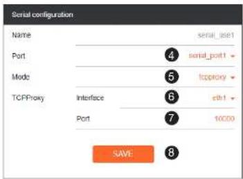
- Under the Serial Configuration window group, click the Port drop-down list and select the desired serial port.
- Click the Mode drop-down list and select Lep proxy.
- Click the TCPProxy > Interface drop-down list and select the desired Ethernet interface.
- Enter the listening port in the TCPPProxy > Port field.
- Click the SAVE button.

ATLONA
a PANDUIT company
Device Operation
Downstream Control using Triggering
TCP/IP traffic received by an encoder or decoder, on the defined IP:Port socket, are translated to RS-232, allowing both control of source or display. Control is achieved using a control system, where all control commands are stored.
Option 1: Defining Commands on the Decoder
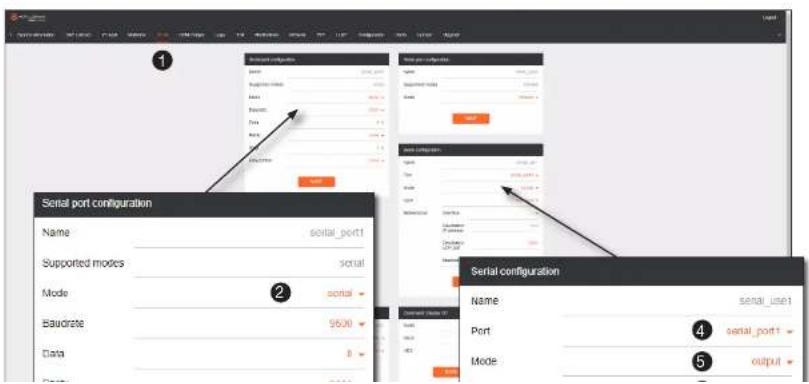
- Login to the decoder and click the Serial menu.
- Under the Serial Port Configuration window group, for the desired serial port, click the Mode drop-down list and select Serial.
- Click the SAVE button.

ATLONA.
a PANDUIT company
Device Operation
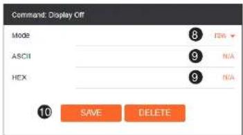
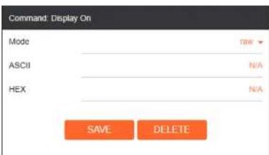
- For each of the available commands, click the Mode drop-down list and select zaw.
The available commands are: Display On, Display Off, Volume Up, and Volume Down. - Enter the command data in either ASCII or hexadecimal format using the ASCII or HEX fields.
- Click the SAVE button.
- Open a Telnet/SSH session with the decoder and trigger display control using the following command:
TrigRS237X Y
where x is the number of the serial port: 1, 2
where Y is the command: on, off, vol+, or vol-.

ATLONA
a PANDUIT company
Device Operation
Option 2: Defining Commands on the Encoder
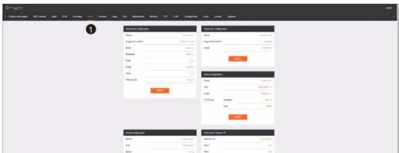
- Login to the encoder and click the Serial menu.
- For each of the available commands, click the Interpret on drop-down list and select decoder.
The available commands are: Display On, Display Off, Volume Up, and Volume Down.

NOTE: Setting the Interpret on drop-down list to encoder implies that commands are defined/stored on the encoder. If set to decoder, commands are defined/stored on the decoder.
- Enter the command data in either ASCII or hexadecimal format using the ASCII or HEX fields.
- Click the SAVE button.

ATLONA.
a PANDUIT company
Device Operation
- Click the Session menu.
- Under the desired Session, locate the AUX section, click the Source drop-down list, and select Commands.
- Click the Enable toggle switch to display the additional fields.
- Enter the destination IP address and UDP port, of the decoder, in the Destination IP address and Destination UDP port fields, respectively. A multicast address can also be entered in the Destination IP address field.
- Click the SAVE button.


ATLONA.
a PANDUIT company
Device Operation
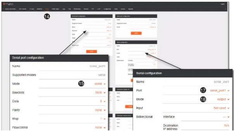
- Click the Serial menu.
- Under Serial port configuration, set the Mode drop-down list to serial.
- Click the SAVE button.
- Under Serial configuration, select the desired port.
- Click the Mode drop-down list and select output.

ATLONA.
a PANDUIT company
Device Operation
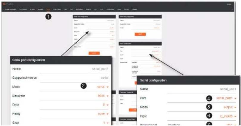
Upstream Control using RS-232
The serial interface provides RS-232 control of both downstream and upstream devices. Source control is provided by enabling bidirectional communication.
- Login to the decoder and click the Serial menu.
- Under the Serial Port Configuration window group, click the Mode drop-down list and select Serial.
- Click the SAVE button.

ATLONA.
a PANDUIT company
Device Operation
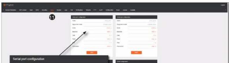
- Enter the destination IP address (the IP address of the encoder) and UDP port in the Bidirectional > Destination IP address and Bidirectional > Destination UDP port field, respectively.
- Click the Bidirectional > Enabled toggle switch to the enabled position. When enabled, the toggle switch will be orange.
- Click the SAVE button.
- Login to the encoder and click the Serial menu.
- Under the Serial Port Configuration window group, click the Mode drop-down list and select Serial.
- Click the SAVE button.
- Under the Serial configuration window group, click the Port drop-down list and select not used.
- Click the SAVE button.


ATLONA.
a PANDUIT company
Device Operation
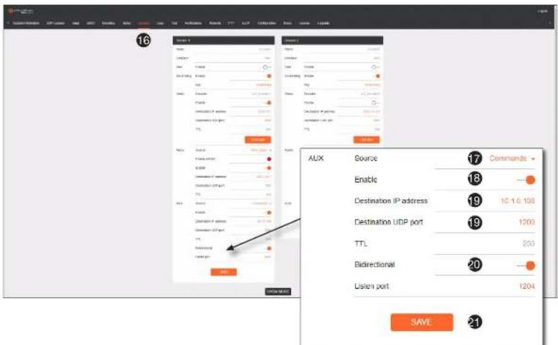
- Enter the destination IP address and UDP port in the Destination IP address and Destination UDP port fields, respectively.
- Click the AUX > Bidirectional toggle switch to enable it. When enabled, the toggle switch will be orange.
- Click the SAVE button.

ATLONA.
a PANDUIT company
Device Operation
Fast Switching
The VCx codec provides fast switching at resolutions up to 4K YUV 4:4:4 @ 60 Hz. This is an improvement over the VC-2 codecs that limited fast switching up to 1920x1200. When the decoder resolution and frame rate are set to Auto, VCx fast switching operates at the preferred resolution and frame rate of the display. In some cases, this preferred resolution and frame rate might not be the maximum supported by the display. If fast-switching is desired at a supported resolution and/or frame rate other than the preferred resolution and frame rate, the decoder can be manually configured for those resolutions.
The fast switching time depends primarily on three things, when switching between streams: resolution, frame rate, and bitrate. For example, a 4K60 stream operating at 750 Mb/s requires \~250 ms to switch. On the other hand, a 1080p stream operating at 750 Mb/s requires less than 50 ms to switch. The time it takes to switch is determined by the amount of time it takes for all the data for a complete frame to be received by the decoder. To improve the fast switching time, decrease the resolution, lower the frame rate, or increase the bitrate.

IMPORTANT: If Fast Switching is enabled, latency increases from 0.5 frames to 1.5 frames.
- Login to the decoder and click HDMI Output in the menu.
- Locate the Fast Switching section and click the Enable toggle switch to enable this feature. When enabled, the toggle switch will be orange.
- Enter the timeout interval, in seconds, in the Timeout(s) field. If fast switching is enabled and the decoder is switched to a different stream, but the stream is not present, then the decoder will hold the last image on the screen. This image will continue to be displayed until either a new stream appears or the decoder is switched to a different stream. Once the timeout interval has expired, the screen will go black. Setting the timeout interval to 0 disables this feature and the last image will be displayed indefinitely.

ATLONA.
a PANDUIT company
Device Operation
Fast Switching FAQs
Question: Does fast switching work between streams of different resolutions?
Answer: Yes. Fast switching can be used between streams with different resolutions and frame rates.
Question: Does fast switching work between HDR and SDR streams?
Answer: Yes, fast switching can be used between HDR and SDR streams; however, it's important to note that some color artifacts may appear during the switch.
Question: Does fast switching work between single streams and multiviews or between multiviews?
Answer: No. Due to the way multiviews work, fast switching is not supported. However, it is not necessary to change the fast switching setting – the decoder will switch as fast as possible between multiviews and return to fast switching when single streams are used.
Question: Does fast switching work on video walls?
Answer: No. Fast switching is not supported when using video walls.

ATLONA.
a PANDUIT company
Device Operation
AES67 Audio
AES67 audio is a standard for high-performance audio streaming over IP, providing several features such as synchronization, media clock identification, and connection management. AES67 does not support bitstream/compressed audio formats, such as Dolby® Digital, and others. Source audio must be transmitted as LPCM up to eight channels at 192 kHz / 24-bit.
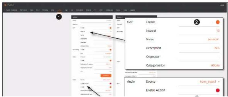
- Login to the encoder and click Session in the menu bar.
- Click the SAP > Enable toggle switch to enable SAP. When enabled, the toggle switch will be orange.
- Locate the Audio section and click the Enable toggle switch. When enabled, the toggle switch will be orange.
- Click the SAVE button to commit changes.

ATLONA.
a PANDUIT company
Device Operation
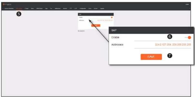
- Go to the decoder and click the SAP Listener menu.
- Click the Enable toggle switch to enable the SAP listener. When enabled, the toggle switch will be orange.
- Click the SAVE button.
- Click the IP Input menu.
- Select the desired IP input for AES67 audio and click the Enable toggle switch. When enabled, the toggle switch will be orange. In the example below, Input 3 is used.
- Enter the address in the Multicost address field

ATLONA
a PANDUIT company
Device Operation
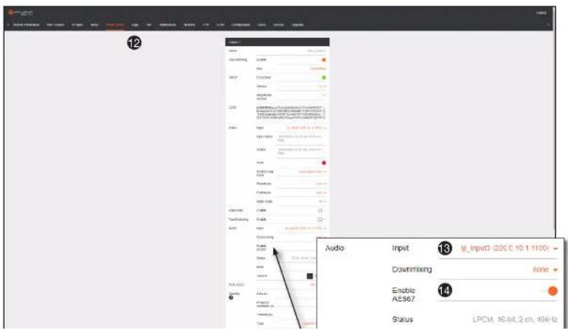
- Click the HDMI Output menu.
- Locate the Audio section, click the Audio > Input drop-down list, and select the input that was configured in Steps 10 and 11.
- Click the Enable AES67 toggle switch to enable it. When enabled, the toggle switch will be orange.
- Click the SAVE button.

ATLONA.
a PANDUIT company
Device Operation
Descrambling
OmniStream supports 128-bit Advanced Encryption Standard (AES) scrambling and is required for HDCP-encrypted video streams. Scrambling can be enabled or disabled and is applied to individual sessions. In order to function properly, scrambling must be enabled on the encoder and descrambling must be enabled on the decoder. The scrambling and descrambling key on both the decoder and all subscribed encoders must be identical. The default scrambling/descrambling key is scrambling.
- Login to the decoder.
- Click HDMI Output in the menu bar.
- Locate the Descrambling section and click the Descrambling > Enable toggle to enable descrambling. Once enabled, the toggle switch will be orange.
- Enter the descrambling key in the Key field. This key must match the key specified on the subscribed encoder, under the Scrambling section.
- Click the SAVE button at the bottom of the HDMI Output window group to commit the changes.

IMPORTANT: If a user-defined key is specified, then it must be a minimum of eight alphanumeric characters. Special characters and spaces are not permitted. Also note that if a key is generated, the same generated key (on the encoder) must also be entered on the decoder, in order to descramble the signal.

ATLONA.
a PANDUIT company
Device Operation
Slate / Logo Insertion
The difference between a “slate” and “logo” is in the size of the image and how it is used: Logos are classified as smaller, low-resolution images that can be positioned at specified locations on the screen. Slates occupy the entire screen. Note that while logos may be used as slates, the image quality will be degraded, as the image will be scaled to fill the screen.
Slate / logo insertion can be performed on both the encoder and decoder. When configured on the encoder, the image that is displayed on the output (decoder) will be from the encoder IP address(es) to which each decoder is subscribed. When configured on the decoder, the image is unique to the specified HDMI output.
Adding Slates / Logos
- Login to the encoder.
- Click Logo in the menu bar.
- Under the New logo window group, enter the name of the logo in the Name field.
- Click the Choose File button and select the desired image. Only .png or .svg files are valid selections.
- Click the UPLOAD button to upload the file.
- A new window group will be created with the name of the logo that was provided in Step 3.
- Perform one of the following:
- If the selected image will be used as a logo, then proceed with Steps 8 through 13.
- If the image will be used as a slate, skip to Step 14 on the next page.
R Under the Long Inception window group, click the Select Long drop-down list and select the desired logo.

ATLONA.
a PANDUIT company
Device Operation
- Click Encoding in the menu bar.
- Click the Slate mode drop-down list, and select Off, Manual, or Auto.
| Slate mode Description | |
| Off | Disables the image from being displayed. |
| Manual | The image will always be displayed, superimposed on the source signal, and will remain even if the source signal is lost. |
| Auto | The image will only be displayed when the source signal is lost.For example, this mode is useful in conference room applications for displaying system instructions when no sources are connected. |
- Click the Slate logo drop-down list and select the desired image. If Slate Mode is set to off, then this field will not be visible.
- Click the SAVE button to apply all changes.
Deleting Slates
- Click Encoding in the menu bar.
- Under the Encoder window group(s), click the Slate mode drop-down list and select off.
- Click the SAVE button at the bottom of the window group to commit changes.
- Click Logo in the menu bar.
- Click the DELETE button for the logo to be removed.

ATLONA.
a PANDUIT company
Device Operation
Text Insertion
Text can be inserted and scrolled across the screen, making it useful for messages and notifications. Several options are available when using text: Scroll speed adjustment (forward, reverse, or static), number of iterations, text color, vertical / horizontal position, as well as transparency.
- Login to the decoder.
- Click Text in the menu bar.
- Under the Text Insertion window group, click the Enable toggle switch. When enabled, this toggle switch will be orange.
- In the Text field, enter the desired text.
- Specify the speed of the scrolling text in the Scroll Speed field. Integer values from -255 to 255 are valid. Negative numbers will scroll the text from left to right. Positive numbers will scroll text from right to left. A value of 0 will not scroll.
- Enter the number of iterations in the Iteration field. Set this field to 0 (zero) to set the number of iterations to infinity.
- Click the Color drop-down list to select the color of the text. The Red, Green, and Blue fields can be changed to further modify the color of the text. Adjust the Alpha field to control the transparency of the text. A value of 255 is opaque and a value of 0 is transparent. Numbers from 0 to 255 are valid for each of these fields.
- Specify the location of the text in the Horizontal (%) and Vertical (%) fields. Each of these values is based on the horizontal and vertical resolution of the video stream.
- Specify the size of the text in the Width (%) and Height (%) fields. Each of these values is based on the horizontal and vertical resolution of the video stream.
- Click the SAVE button to commit all changes.

ATLONA.
a PANDUIT company
Device Operation
Configuring a Static IP Address
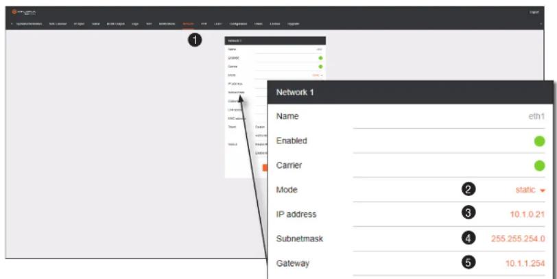
There will be situations where it is desirable for the encoder to be assigned a static IP address. Some IT environments prefer this method, as opposed to having a DHCP server dynamically assign IP addresses. If the decoder is unable to detect a DHCP server within 15 seconds, then Automatic Private IP Addressing (APIPA) will be used to assign the encoder an address within the IPv4 address block 169.254.xxx.xxx/16. If this occurs, connect an Ethernet cable directly from the ETHERNET port of the encoder to the LAN port of a computer, then follow the instructions below.
- Login to the web server and click Network in the menu bar.

ATLONA.
a PANDUIT company
Device Operation
Creating Video Walls
Introduction
Before proceeding with creating video walls, review the tables below. These tables provide information on video wall size, maximum timing, color space, and bit depth.

NOTE: OmniStream video walls do not support interlaced sources.
The following table lists the maximum video wall size, based on the resolution of the source.
| Resolution Maximum Video Wall Size | |
| 4Kp60 2 x 2 | |
| 4Kp30 16 x 16 | |
| 1080p60 n x n (no limit) | |
The following table provides maximum timing, color space, and bit-depth specifications when video walls are enabled.
| Number of Channels Resolution Refresh Rate Color Space Bit Depth | |||
| 1 1920 x 1080p 60 Hz | 4:4:4 12-bit | ||
| 2 1920 x 1080p 30 Hz | 4:4:4 12-bit | ||

NOTE: When video walls are enabled, the output resolution at the decoder endpoint is dependent on both the number of channels on the decoder and the input resolution received from the encoder. Refer to the table below for details.

ATLONA.
a PANDUIT company
Device Operation
Landscape Mode
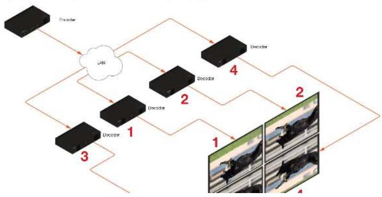
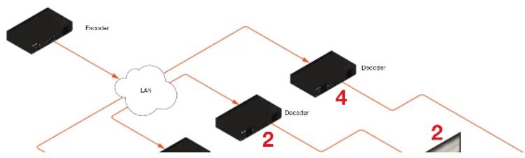
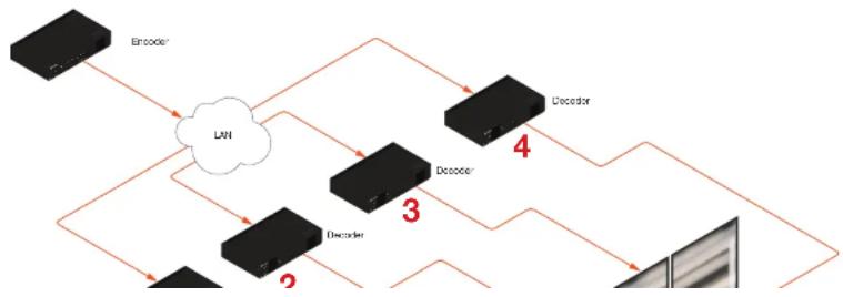
The following diagram will be used to illustrate how to configure a 2 x 2 video wall. The details of this diagram are listed below:
- Four decoders are subscribed to a single encoder. Each decoder is connected to a display.
• The encoder is transmitting a 3840 x 2160 video signal.
• The top two displays have been accidentally mounted upside down.
Figure 1.1: Landscape-mode 2x2 video wall requiring adjustment.
flowchart
graph TD
    A["Encoder"] --> B["CAN"]
    B --> C["Decoder 1"]
    B --> D["Decoder 2"]
    B --> E["Decoder 4"]
    C --> F["1"]
    D --> G["2"]
    E --> H["2"]
    F --> I["1"]
    G --> J["1"]
    H --> K["1"]
    I --> L["4"]
    J --> M["4"]

ATLONA
a PANDUIT company
Device Operation
Note that the order in which each image is cropped, scaled, and/or rotated is arbitrary. In this example, the configuration process will begin with Display 1, in the top left.
- Login to the decoder and click the HDMI Output menu.
- Under the Video section, click the Stretch/Crop Mode drop-down list and select Full Screen. This guarantees that the image will fill the screen.
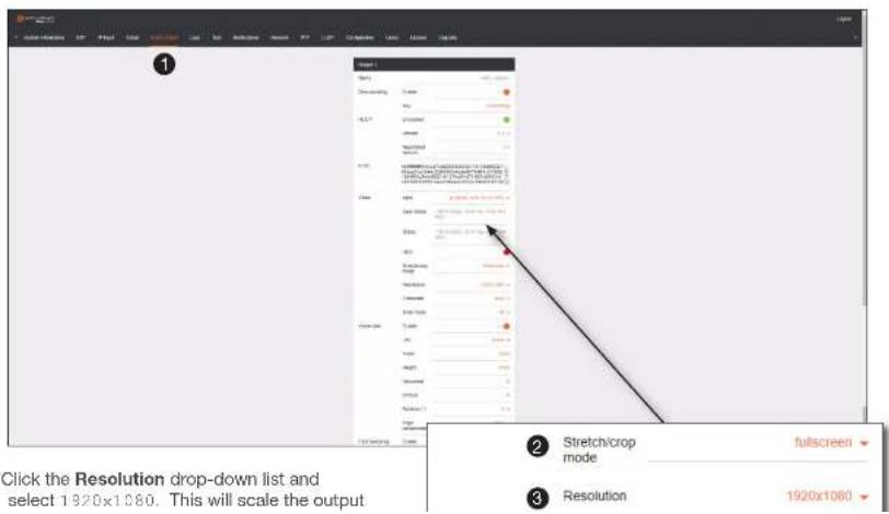
- Click the Resolution drop-down list and select 1920x1080. This will scale the output

ATLONA.
a PANDUIT company
Device Operation
- Enter the starting coordinates of the portion of the source stream that will be displayed on this decoder in the Horizontal and Vertical fields.. These values are the pixel start position (upper left most pixel). The table below lists left and right coordinates for a 2x2 video wall, with the specified source resolution.
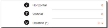
Table listing width and height examples for 2x2 video wall.
| Source resolution Width (pixels) Height (pixels) | ||
| 3840 x 2160 (UHD) 1920 10801920 x 1080 (1080p) 960 540 | ||
Table listing left and right coordinates for a 2x2 video wall.
| Source resolution Upper Left Upper Right Lower Left | Lower Right | |||
| 3840 x 2160 (UHD) | 0, 0 | 1920, 0 | 0, 1080 | 1920, 1080 |
| 1920 x 1080 (1080p) | 0, 0 | 960, 0 | 0, 540 | 960, 540 |
- Click the Rotation drop-down list to select the rotation angle of the image. In this example, select 180 from the drop-down list. The image will be flipped, vertically. This step is only applied when configuring the two top displays.

NOTE: 0 and 180 used for landscape mode video walls and 90 and 270 for portrait mode. Refer to Portrait Mode (page 63) for more information.
The image on Display 1 in the upper-left corner, as illustrated below, has been cropped and rotated and is now

ATLONA.
a PANDUIT company
Device Operation
- Click the SAVE button at the bottom of the screen to commit changes.
- Repeat steps 3 through 9 for decoders 2, 3, and 4. Note that in the example below, decoders 3 and 4 will not require any rotation. Therefore, make sure the Rotation option is set to 0 for decoders 3 and 4.

IMPORTANT: When using dual-channel decoders, the Rotation feature can only be used when a single HDMI channel is active. Image rotation is not supported on dual-channel decoders when both HDMI channels are active. Single-channel decoders do not have this restriction.
Once all four decoders have been properly configured, the image will be correctly displayed across all four displays. Refer to the illustration on the next page.
- Check the image, on each display, and make sure they are aligned correctly with the other images on the video wall. Use the Edge Compensation drop-down list to adjust bezel compensation, if necessary. Refer to Bezel Compensation (page 68) for more information.
Figure 1.3: Landscape-mode 2 x 2 video wall displayed correctly.
flowchart
graph TD
    A["Encoder"] --> B["LAN"]
    B --> C["Decoder"]
    C --> D["Uncoder"]
    D --> E["2"]
    C --> F["2"]
    B --> G["2"]

ATLONA.
a PANDUIT company
Device Operation
Portrait Mode

IMPORTANT: Portrait Mode is only supported on single-channel decoders.
Images can be rotated 90^ or 270^ to create portrait-oriented video walls. The steps to configure portrait-oriented video walls is very similar to creating landscape video walls.
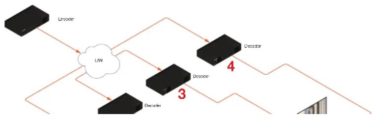
A similar scenario to the landscape video wall challenge will be used to illustrate how to configure a 1 x 4 portrait-oriented video wall. The details of this diagram are listed below:
- Four decoders are subscribed to a single encoder. Each decoder is connected to a display.
- The encoder is transmitting a 3840 x 2160 video signal.
- Display 2 and 3 have been mounted upside-down.
Figure 2.1: Portait-mode video wall requiring adjustment.
flowchart
graph TD
    A["Encoder"] --> B["UN"]
    B --> C["Decoder"]
    C --> D["Decoder"]
    D --> E["4"]
    B --> F["3"]
    F --> G["Decodcr"]

ATLONA.
a PANDUIT company
Device Operation
- Login to the decoder and click HDMI Output in the menu.
- Under the Video section, click the Stretch/Crop Mode drop-down list and select Full Screen. This guarantees that the image will fill the screen.
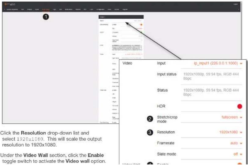
- Click the Resolution drop-down list and select 1920x1080. This will scale the output resolution to 1920x1080.
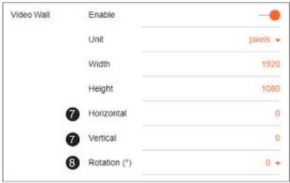
- Under the Video Wall section, click the Enable toggle switch to activate the Video wall option.

ATLONA.
a PANDUIT company
Device Operation
- Enter the starting coordinates of the portion of the source stream that will be displayed on this decoder in the Horizontal and Vertical fields. These values are the pixel start position (upper left most pixel). The table on the next page lists left and right coordinates for a 1x4 video wall, with the specified source resolution.
- Click the Rotation drop-down list to select the rotation angle of the image. In this example, select 90 from the drop-down list to rotate the image as portrait. The image on Display 1 is now cropped and rotated and is displayed correctly. At this point, one-fourth of the video wall has been configured.
- Click the SAVE button at the bottom of the screen to commit changes.

ATLONA.
a PANDUIT company
Device Operation

NOTE: 0 and 180 used for landscape mode video walls and 90 and 270 for portrait mode. Refer to Portrait Mode (page 63) for more information.
Table listing width and height examples for 1x4 video wall.
| Source resolution Width (pixels) Height (pixels) | ||
| 3840 x 2160 (UHD) 1920 10801920 x 1080 (1080p) 960 540 | ||
Table listing left and right coordinates for a 1x4 video wall.
| Source resolution Upper Left Upper Right Lower Left Lower Right | ||
| 3840 x 2160 (UHD) 0, 0 1920, 0 0, 1080 1920, 1080 | ||
| 1920 x 1080 (1080p) 0, 0 960, 0 0, 540 960, 540 |
The image on Display 1 is now cropped and rotated and is displayed correctly. At this point, one-fourth of the video wall has been configured.
Figure 2.2: Portait-mode 1 x 4 video wall with Display 1 properly oriented.
flowchart
graph LR
    A["Encoder"] --> B["Decoder"]
    B --> C["Feedback Line"]
    C --> A

ATLONA.
a PANDUIT company
Device Operation
- Repeat steps 3 through 9 for decoders 2, 3, and 4. Since display 2 and 3 were mounted upside-down, they will require a rotation of 180^ (to flip horizontally) + 90^ (to align them as portrait), giving a total rotation of 270^ .

IMPORTANT: When using dual-channel decoders, the Rotation feature can only be used when a single HDMI channel is active. Image rotation is not supported on dual-channel decoders when both HDMI channels are active. Single-channel decoders do not have this restriction.
Once all four decoders have been properly configured, the image will be correctly displayed across all four displays. Refer to the illustration on the next page.
- Check the image, on each display, and make sure they are aligned correctly with the other images on the video wall. Use the Edge Compensation drop-down list to adjust bevel compensation, if necessary. Refer to Bezel Compensation (page 68) for more information.
Figure 2.3: Portait-mode 1 x 4 video wall displayed correctly.
flowchart
graph TD
    A["Encoder"] --> B["LAN"]
    B --> C["Decoder 2"]
    B --> D["Decoder 3"]
    B --> E["Decoder 4"]
    C --> F["Signal"]
    D --> F
    E --> F

ATLONA.
a PANDUIT company
Device Operation
Bezel Compensation
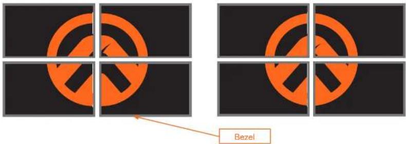
Displays have a region where video is not displayed, called the bezel. This can cause display issues when creating video walls. Bezel compensation takes this area into account when a single video source is mapped across multiple displays. Bezel compensation can be adjusted at any time.
The illustration on the left shows a simple 2x2 video wall without bezel compensation. Note how the Atlona logo appears stretched, horizontally. On the right, bezel compensation is used to correct the image.
Image without bezel compensation Image with bezel compensation applied
-
Under the Video Wall section, click the Edge compensation drop-down list and select Bezel compensation.
-
Enter the Top, Bottom, Left, and Right values, as desired. Values can be entered in pixels, inches, or millimeters.
-
On the AVE button of the button of the Osteo window measure to correct clearance

ATLONA.
a PANDUIT company
Configuration and Management Interfaces
Web Server

NOTE: This section assumes that the System mode is set to vcx. If vc-2 video is used, some features on these pages will not be available.
System information page
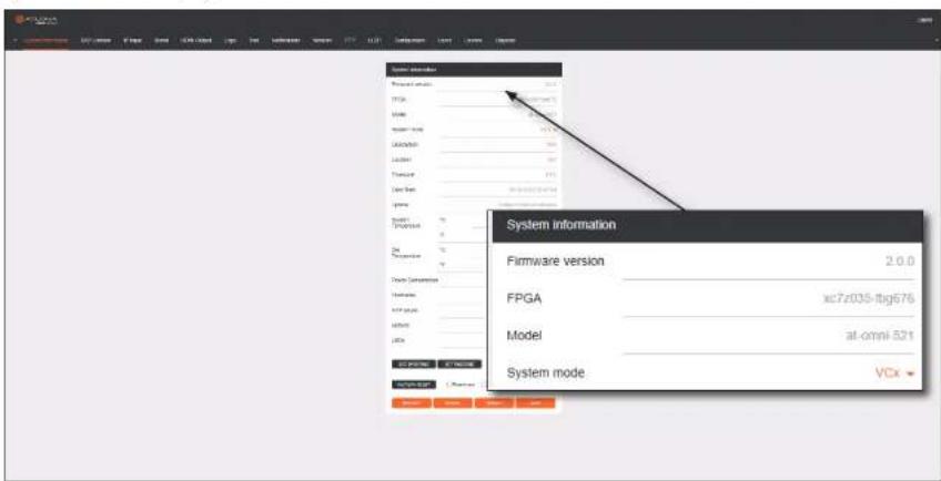
Eirmware version

ATLONA.
a PANDUIT company
Configuration and Management Interfaces
Description
Provides the option of assigning descriptive name to the unit.
Location
Provides the option of assigning a description of where the unit is located.
Timezone
Displays the time zone format. Click the SET TIMEZONE button, to assign the time zone.
Date/Time
Displays the current date and time. Click the SET DATE/TIME button to set these values.
Uptime
Displays the elapsed time since the unit was powered-on or rebooted.
System Temperature
Displays the ambient enclosure temperature.
Die Temperature
Displays the value returned from the die temperature sensor (DTS) on the chip of the PCB.
Power Consumption
Displays the precise power consumption of the encoder.
Hostname


ATLONA.
a PANDUIT company
Configuration and Management Interfaces
FACTORY RESET
Click this button to reset the encoder to factory-default settings. When performing a factory reset, the following options can be selected, by clicking the check box. If no options are selected, then the encoder is reset with no factory-default settings.
Option Description
| None Checked Resets the decoder with factory-default settings. |
| Reset User Resets the decoder to factory-default settings and resets custom user information. |
| Reset Network Resets the decoder to factory-default settings and resets network information. |
| Reset Defaults Resets the encoder to factory-default settings and restores a default device configuration that includes defined multicast addresses. |
IDENTIFY
Click this button to physically identify a unit on the network. Clicking this button will cause all front-panel LED indicators to flash for 10 seconds.
DEBUG
Click this button to instruct the unit to create a debug file. This file is used by Atlona Technical Support Engineers to diagnose internal issues with the unit.
REBOOT
Click this button to perform a soft reboot of the encoder.
SAVE
Click this button to commit changes to the settings on this page.

ATLONA.
a PANDUIT company
Configuration and Management Interfaces
SAP Listener page
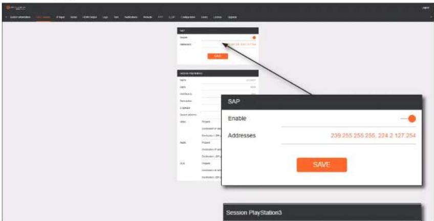
Enable
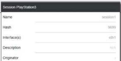
Click this toggle to enable or disable SAP. This feature is enabled when the toggle switch is orange. This is the default setting. If an SAP announcement is picked up, it will be displayed below the SAP window group (as shown here).
...

ATLONA
a PANDUIT company
Configuration and Management Interfaces
IP Input page
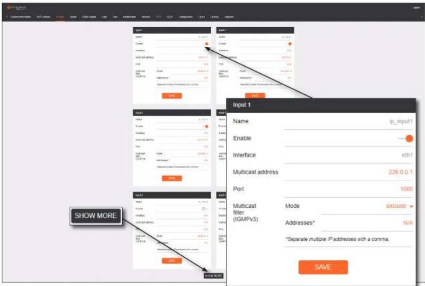
Input window group

ATLONA.
a PANDUIT company
Configuration and Management Interfaces
Serial page
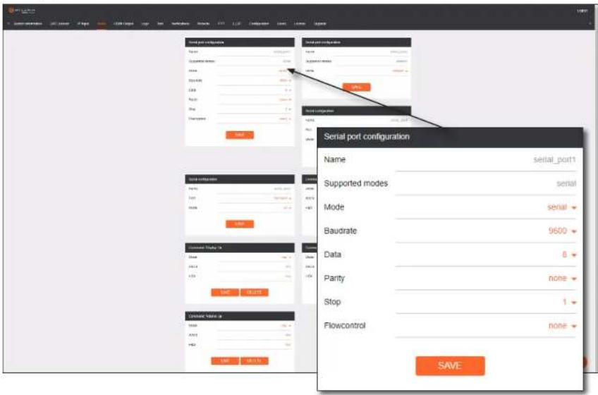
Serial port configuration window groups

ATLONA.
a PANDUIT company
Configuration and Management Interfaces
Serial configuration window groups
The following fields apply to both Serial configuration window groups.
Name
The name of the port. This field cannot be changed.
Port
Click this drop-down list to select the desired serial port.
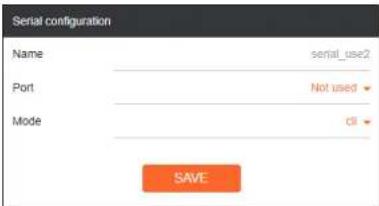
Mode
Click this drop-down list to select the desired control mode. Available values are: cli, tcpproxy, and output. Select tcpproxy to translate received IP control traffic to RS-232 output. Selecting the cli option will force the serial port to function as a Command-Line Interface (CLI) for control of the encoder. Refer to Device Control (page 35) for more information.
SAVE
Click this button to commit all changes within the Serial configuration window group.
Command window groups
By default, window groups for the following commands are created: Display Off, Display On, Volume Down, and Volume Up.
Interpret on
Click this drop-down list to select the endpoint where the command will be processed: encoder or decoder.
ASCII
Enter the ASCII representation of the command string in

ATLONA.
a PANDUIT company
Configuration and Management Interfaces
HDMI Output page

ATLONA.
a PANDUIT company
Configuration and Management Interfaces
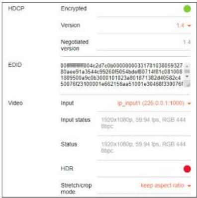
HDCP > Encrypted
This indicator will be green if the stream content is HDCP-encrypted.
HDCP > Version
Click this drop-down list to select the supported version of HDCP.
HDCP > Negotiated version
Displays the version of HDCP used by the stream.
EDID
This field will display the EDID of the connected display. This raw data can be copied and stored under the EDID, if desired.
Video > Input
Click this drop-down list to select the desired IP input. Available options are ip_input1 - ip_input16, none, generator, and multiview (if configured).
Video > Input status
Displays the input status. If no video stream is detected, then "No active video" will be displayed.
Video > Status
Displays the active video input. If no input is active or detected, then this field will display "No active video".
Video > HDR
This indicator will be green if HDR video is present.
Video > Stretch / Crop Mode
Click this drop-down list to select the aspect ratio.

ATLONA.
a PANDUIT company
Configuration and Management Interfaces
Video > Resolution
Click this drop-down list to select the desired output resolution. This is a scaler feature which can either upscale or downscale the output on the decoder. If input is selected, then no scaling will be applied to the output. Select Auto to use the EDID of the sink device to determine the output resolution.
| Resolution | 1920x1080 |
| Framerate | auto |
| Slate mode | off |
| Resolutions | |
| Input 1440x1050 | |
| Auto 1440x900 | |
| 4096x2160 1280x1024 | |
| 3840x2160 1280x800 | |
| 1920x1200 1280x768 | |
| 1920x1060 1280x720 | |
| 1680x1050 1024x768 | |
| 1600x900 | |

NOTE: When working with VESA resolutions 1360x768p60 and 1366x768p60, the Resolution drop-down list must be set to Auto.
Video > Framerate
Sets the output frame rate. Available options are auto, 60 Hz, 50 Hz, and 30 Hz, except for the AT-OMNI-122 where the options are auto and 30 Hz.
Video > Slate Mode
Click this drop-down list to select the slate mode. Refer to Slate / Logo Insertion (page 54) for more information.

ATLONA.
a PANDUIT company
Configuration and Management Interfaces
Video Wall > Horizontal
The number of video wall rows.
Video Wall > Vertical
The number of video wall columns.
Video Wall > Rotation
Adjusts the rotation angle of the image. Available options are 0, 90, 180, and 270.
Video Wall > Edge compensation
Adjusts edge compensation. Available options are none, bezel compensation, and edge blending.
Video Wall > Top
Offset value for adjusting the top portion of the image. Units are specified in the Unit field.
Video Wall > Bottom
Offset value for adjusting the bottom portion of the image. Units are specified in the Unit field.
Video Wall > Left
Offset value for adjusting the left portion of the image. Units are specified in the Unit field.
Video Wall > Right
Offset value for adjusting the right portion of the image. Units are specified in the Unit field.
Fast Switching > Enable
Click this toggle switch to enable or disable fast-
| Horizontal | 0 | |
| Vertical | 0 | |
| Rotation (°) | 0 | |
| Edge compensation | none | |
| Fast Switching | Enable Horizontal | 0 |
| Vertical | 0 | |
| Rotation (°) | 0 | |
| Edge compensation | bezel compensation | |
| Top | 0 | |
| Bottom | 0 | |
| Left | 0 | |
| Right | 0 | |
| Fast Switching | Enable | 0 |
| Timeout (s) | 5 | |
| Audio | Input | lp_input3 (225.0 10 1:1100) |
| Downmixing | none | |
| Enable AES67 | ○ |

ATLONA.
a PANDUIT company
Configuration and Management Interfaces
Audio > Volume
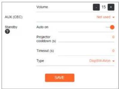
Click the speaker icon on the left to decrease volume. Click the speaker icon on the right to increase volume. Range: 0 to 15.
AUX (CEC)
Click this drop-down list to select the desired IP input for CEC control. Available options are ip_input1 - ip_input12, none, and generator.
Standby > Auto On
Click this toggle switch to enable or disable power-on. When enabled this toggle switch will be green and the power-on command will be sent to the display when an A/V signal is detected.
Standby > Projector Cooldown (s)
Enter the time interval, in seconds, before the projector can be powered-off. This time interval prevents the decoder from sending additional commands until the projector has had time to complete its cool-down process.
Standby > Timeout (s)
Enter the time interval, in seconds, before the next command can be accepted by the display.
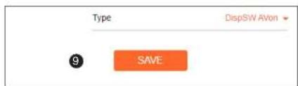
Standby > Type
Click this drop-down list to select the display mode.
Type Description
| DispSW AVon Display switches on/off, source audio/video signal always on. |
| DispSW AVSW Display switches on/off, source audio/video signal switches on/off. |
| AV SW Display is always on, source audio/video signal switches on/off |
| Always on Display is always on, source audio/video signal always on. |

ATLONA.
a PANDUIT company
Configuration and Management Interfaces
Logo page
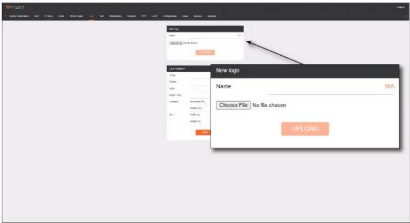
New logo window group
Name
Enter a name for the logo in this field.
Choose File

ATLONA.
a PANDUIT company
Configuration and Management Interfaces
Horizontal (%)
Enter the horizontal position of the logo based on the resolution of the video stream.
Vertical (%)
Enter the vertical position of the logo based on the resolution of the video stream.
Width (%)
Enter the width of the logo. This value is based on the horizontal resolution of the video stream.
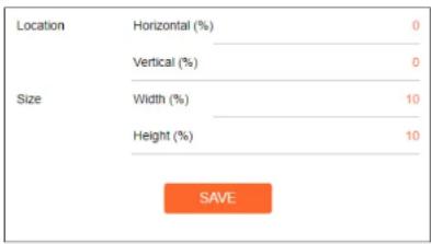
Height (%)
Enter the height of the logo. This value is based on the vertical resolution of the video stream.
SAVE
Click this button to commit all changes within the Logo Insertion window group.

ATLONA.
a PANDUIT company
Configuration and Management Interfaces
Text page
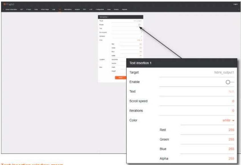
Text insertion window group

ATLONA.
a PANDUIT company
Configuration and Management Interfaces
Location > Horizontal
Enter the horizontal position of the text, based on the resolution of the video stream.
Location > Vertical
Enter the vertical position of the text, based on the resolution of the video stream.
Location > Width
Enter the width of the text. This value is based on the horizontal resolution of the video stream.
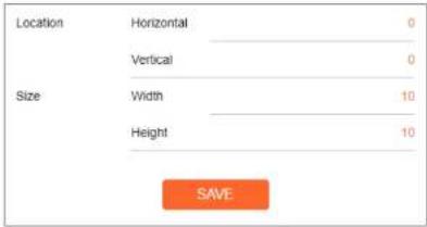
Location > Height
Enter the height of the text. This value is based on the vertical resolution of the video stream.
SAVE
Click this button to commit all changes within the Text insertion window group.

ATLONA.
a PANDUIT company
Configuration and Management Interfaces
Network page
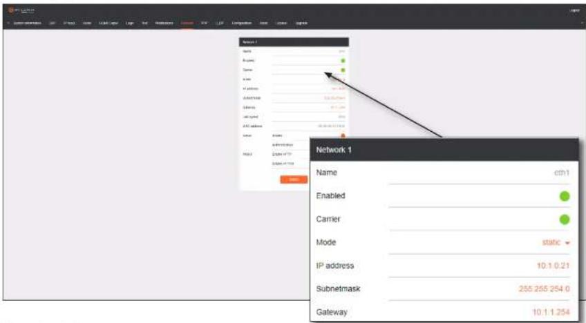
Network window groups
The following fields apply to both Network window groups. The single-channel decoder will only have one Network window group.
Name

ATLONA.
a PANDUIT company
Configuration and Management Interfaces
Link speed
Displays the Ethernet interface link speed in Mbps. This field cannot be modified.
MAC address
Displays the MAC address of the Ethernet interface.
Telnet > Enable
Click this toggle switch to enable or disable Telnet. If disabled, then Telnet sessions to the decoder cannot be established.
Telnet > Authentication
Click this toggle switch to enable or disable Telnet authentication. If enabled, then the toggle switch will be orange. Once enabled, connecting to the decoder using Telnet will require login credentials. The default credentials are:
Username: admin
Password: Ationa

WebUI > Enable HTTP
Click this toggle switch to enable or disable HTTP. If disabled, traffic on port 80 is forbidden.
WebUI > Enable HTTPS
Click this toggle switch to enable or disable HTTPS. If disabled, traffic on port 443 is forbidden.
SAVE
Click this button to commit all changes within the Network window group.

ATLONA.
a PANDUIT company
Configuration and Management Interfaces
PTP page
The PTP page provides options for adjust Precision Time Protocol (PTP) for AES67 audio streams. PTP is used by AES67 to keep all audio streams synchronized.
For a system utilizing PTP, all devices undergo an automatic self-election process to choose the device to be used as the PTP grandmaster (GM) clock, based on the accuracy of the device's clock and the device's configured priority. A lower priority number means the device is more likely to get selected as the GM. OmniStream runs 1 PTP daemon per Ethernet interface.

IMPORTANT: If a new device is added to the network and the GM changes, a brief outage will be experienced while all connected devices synchronize with the new clock. Because of this, Atlona recommends that one unit gets manually defined as the GM and have both Priority 1 and Priority 2 fields be set to 1.
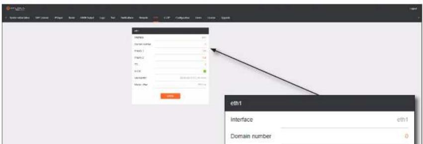

ATLONA.
a PANDUIT company
Configuration and Management Interfaces
TTL
Displays the TTL value. The default IPV4 TTL value used for PTP is 8.
Is GM
If the indicator is green, then this interface is the PTP GM.
GM Identity
The grandmaster clock identity.
Master Offset
Displays the grandmaster clock offset.
SAVE
Click this button to commit all changes.
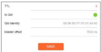

ATLONA.
a PANDUIT company
Configuration and Management Interfaces
LLDP page
The Link Layer Discovery Protocol (LLDP) page returns information about the switch that is connected to the decoder.

NOTE: LLDP must be enabled on the switch that the decoders are connected to, in order for the switch information to be displayed.


ATLONA.
a PANDUIT company
Configuration and Management Interfaces
Configuration page
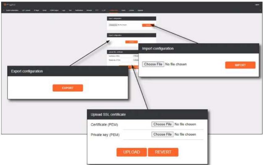
flowchart
graph TD
    A["Export configuration"] --> B["Import configuration"]
    B --> C["Upload SSL certificate"]
    C --> D["Upload SSL certificate"]
    D --> E["Export configuration"]
    E --> F["Import configuration"]
    F --> G["Upload SSL certificate"]
    G --> H["Upload SSL certificate"]
    H --> I["Export configuration"]
    I --> J["Import configuration"]
    J --> K["Upload SSL certificate"]
    K --> L["Upload SSL certificate"]
    L --> M["Export configuration"]
    M --> N["Import configuration"]
    N --> O["Upload SSL certificate"]
    O --> P["Export configuration"]
    P --> Q["Import configuration"]
    Q --> R["Upload SSL certificate"]
Import configuration

ATLONA.
a PANDUIT company
Configuration and Management Interfaces
Users page
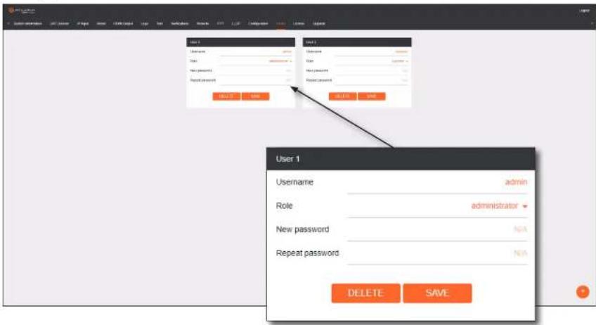
User window groups
The following fields apply to all User window groups.
Username
Enter the desired usemame in this field.

ATLONA.
a PANDUIT company
Configuration and Management Interfaces
License page
This page displays all installed licenses and allows additional licenses to be installed.
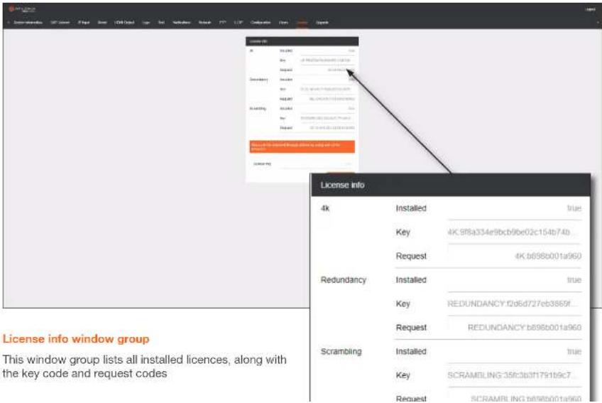
License info window group
This window group lists all installed licences, along with the key code and request codes

ATLONA.
a PANDUIT company
Configuration and Management Interfaces
Upgrade page
This page is used to update the firmware on the encoder.
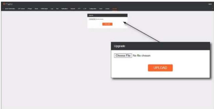
Upgrade window group
Choose File
Click this button to select the firmware file to be uploaded.

ATLONA.
a PANDUIT company
Appendix
Updating the Firmware
Follow the procedure below to update OmniStream units using the built-in web server.
- Launch the desired web browser and enter the IP address of the encoder/decoder in the address bar.
- Enter the username and password. Note that the password field will always be masked. The default credentials are:
Username: admin Password: Ationa
- The System Information page will be displayed.
- Click Upgrade in the menu bar to display the Upgrade page.
- Click the Choose File button.

ATLONA
a PANDUIT company
Appendix
Performing a Link Test
Follow the procedure below to perform a link integrity test between an encoder and decoder(s).
- Launch a web browser and enter the IP address of the encoder in the address bar.
- Open another tab in the browser and enter the IP address of the subscribing decoder in the address bar.
- Verify that all desired decoders are subscribed to the encoder's multicast address and port number. In the decoder example below, the IP Input > Input 1 > Multicast address field is set to 225.0.0.11. This is the same IP address that is assigned to the Session > Session 1 > Destination IP address field on the encoder.
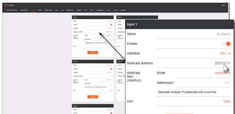

ATLONA.
a PANDUIT company
Appendix
- An orange screen with a progress bar will be displayed during the testing procedure.
bar
| Category | Value (%) | |---|---| | Bar | 58 |- After the test, the encoder web page will automatically redirect to the Notifications tab where the user can see the results.
If the test passed, information similar to the following will be displayed. Note the information in the Description field: "100% of packets received by ..." indicates no packets were dropped / zero loss.


ATLONA.
a PANDUIT company
Appendix
If the test fails, it could be that less than 100% of packets are received, indicating connectivity, but with some amount of packet loss. If it shows "No one replied!" or if the target decoder is not shown in results, it could indicate that there is a connectivity issue or that the decoder is not subscribed to the correct video multicast address.
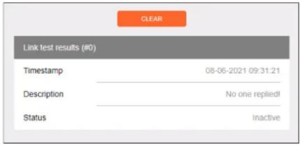
Hovering the mouse over the Description field will provide the full IP address of each decoder which received the test, as shown below. If multiple decoders were tested, additional IP addresses will be displayed.
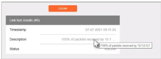

ATLONA.
a PANDUIT company
Appendix
Mounting Instructions
OmniStream decoders includes two mounting brackets and four mounting screws, which can be used to attach the unit to any flat surface.
- Using a small Phillips screwdriver, remove the two screws from the left side of the enclosure.
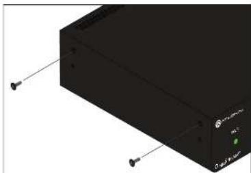
natural_image
3D rendering of a black electronic device with ports and connectors (no visible text or symbols)- Position one of the rack ears, as shown below, aligning the holes on the side of the enclosure with one set of holes on the rack ear.
- Use the enclosure screws to secure the rack ear to the enclosure.
Included screws

- Mount the unit using the oval-shaped holes, on each rack ear. If using a drywall surface, a #6 drywall screw is recommended.
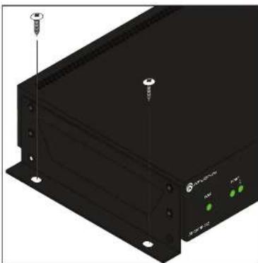
natural_image
3D rendering of a black electronic device with labeled ports and mounting holes (no readable text or symbols)
NOTE: Rack ears can also be inverted to mount the unit under a table or other flat surface.

ATLONA
a PANDUIT company
Appendix
Rack Tray for OmniStream
OmniStream decoders can also be mounted in the OmniStream rack tray (AT-OMNI-1XX-RACK-1RU). The rack tray is sold separately and provides easy mounting and organization of up to two OmniStream encoders/decoders in a convenient 1U rack tray. The OmniStream rack tray can be purchased directly from Atlona.
- Position the OmniStream products, as shown in the illustration below.
- Using the included screws, secure each unit to the rack with a Philips screwdriver.

NOTE: OmniStream units can be mounted forward-facing or back-facing, depending upon your requirements.
- Install the entire assembly into an empty 1U slot in the rack.
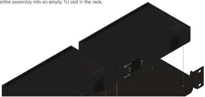
natural_image
3D rendering of a black mechanical component with mounting holes and internal slots (no text or symbols visible)
ATLONA.
a PANDUIT company
Appendix
Specifications
| Video | ||
| Signal HDMI | ||
| Copy Protection HDCP 2.2 | ||
| UHD/HD/SD 4096×2160 (DCI) @ 30/24 Hz | 1920 × 1080^(7) @ 25/29.97/30 Hz | |
| 3840 × 2160^(1) (UHD) @ 60/50/24/25/30 Hz | 1280 × 720p @ 30/50/59.94/60 Hz | |
| 1920 × 1080p @ 23.98/24/25/29.97/30/50 /59.94/60 Hz | ||
| VESA ^(3) | 2560×1600 | 1366×768 |
| 1920×1200 | 1360×768 | |
| 1680×1050 | 1280×1024 | |
| 1600×1200 | 1280×800 | |
| 1600×900 | 1280×768 | |
| 1440×900 | 1152×768 | |
| 1400×1050 | 1024×768 | |
| Color Space YUV, RGB | ||
| Encoding | |||
| Density Single decoding engine | |||
| Compression Format VCx and VC-2 (SMPTE-2042) | |||
| Video Quality Optimization User-selectable: PC Application or Video mode (VC-2 codec only) | |||
| Chroma Subsampling Chroma | VCx VC-2 Video | ||
| 4:4:4 | Yes | No | |
| 4:2:2 | Yes | No | |
| 4:2:0 | Yes | Yes | |
| Color Depth | 8-bit, 10-bit, 12-bit | ||
| HDR | HDR10, HLG, Dolby® VisionTM | ||

ATLONA.
a PANDUIT company
Appendix
Protocols
| Video Streaming RTP | |
| Audio Streaming RTP, up to 7.1 channels | |
| AES67, up to LPCM 7.1 channels | |
| Addressing DHCP, static | |
| Encryption AES-128 | |
| QoS Tagging RFC 2475 | |
| Discovery Multicast DNS, LLDF, SAP | |
| Management HTTPS, SSH, Telnet, and WebSockets with TLS | |
| IP Multicast IGMPv2 and IGMPv3 support | |
Graphics Features
| Text Insertion | Adjustable height/width, scrolling (speed, direction, or static), iterations (up to infinite), positioning, and adjustable color and alpha (transparency) channels. |
| Slate / Logo Insertion ^10 | PNG file format, adjustable aspect ratio (keep or stretch), horizontal/vertical size, screen position; slate mode can be set to off, manual (image always displayed, superimposed on the source signal, and will remain if source signal is lost), auto (image will only be displayed when source signal is lost). |
Control
| CEC Supported and triggered from control systems and OmniStream encoders | |
| RS-232 | Device control and configuration; supports baud rates from 2400 to 9600Bidirectional pass-through from control system to networkBidirectional TCP Proxy (RS-232 commands over IP) |
| IR Pass-through from control system to network | Pass-through from network to control system |
Connectors
| HDMI 1 - Type A, 19-pin, female, locking |

ATLONA.
a PANDUIT company
Appendix
| Chassis Inches Millimeters | ||
| Dimensions (H x W x D) | 1.34 x 8.19 x 4.41 | 34 x 208 x 112 |
| Weight Pounds Kilograms | ||
| Unit 1.5 0.7 | ||
| Certification | ||
| Device CE, FCC, CB, RoHS | ||
| Compliance | ||
| NDAA-899 Yes | ||
| TAA Yes | ||
| Warranty | ||
| Device To view the product warranty, use the following link:https://atlona.com/warranty | ||
Footnotes
(1) Using VCx, streaming is supported up to 4K60 4:4:4. Using VC-2 Video Mode, 4K60 and 4K50 resolutions will be chroma subsampled to 4:2:0 before streaming.
(2) Interlaced sources are passed-through without modification, and do not support scaling, video wall, logo insertion, text insertion, or fast switching.
(3) All VESA resolutions are 60 Hz.
(4) Slate insertion is limited to 1080p only.
(5) Maximum distance per hop is 330 feet (100 meters), depending upon network configuration.

ATLONA.
a PANDUIT company

- Single-Channel Networked AV Decoder
- Version Information
- Sales, Marketing, and Customer Support
- Main Office
- International Headquarters
- Operating Notes
- Warranty
- Important Safety Information
- CAUTION
- OF ELECTRIC SH DO NOT OPEN
- Panel Description 12
- Getting Started 17
- Table of Contents
- Device Operation 35
- Configuration and Management Interfaces
- Introduction
- Features
- Package Contents
- Introduction to OmniStream
- OmniStream 101
- DEFINITIONS
- IP Address Assignment
- Network Bandwidth and OmniStream Compression
- Streams
- Subscribing to a Stream
- OmniStream Naming Schema
- PWR
- LINK
- Reboot button
- HDMI OUT
- Installation
- RS-232 Connections
- IR Connections
- Connection Instructions
- Getting Started
- ID Button
- Broadcast Messaging
- Resetting to Factory-Defaults
- Using the ID button
- Using the Mclear command
- Using the Web Server
- LED Indicators
- Accessing the Web Server
- Basic Configuration Tutorial
- Setting the System Mode
- Configuring Inputs
- Encoder Settings
- Creating a Session
- Subscribing to an Encoder
- Video Configuration
- Audio Configuration
- Configuring the HDMI Output Stream
- Troubleshooting
- Encoder Checklist
- Decoder Checklist
- Device Operation
- Device Control
- Control using TCP Proxy
- Downstream Control using Triggering
- Option 1: Defining Commands on the Decoder
- Option 2: Defining Commands on the Encoder
- Upstream Control using RS-232
- Fast Switching
- Fast Switching FAQs
- AES67 Audio
- Descrambling
- Slate / Logo Insertion
- Adding Slates / Logos
- Deleting Slates
- Text Insertion
- Configuring a Static IP Address
- Creating Video Walls
- Landscape Mode
- Portrait Mode
- Bezel Compensation
- Web Server
- Description
- Location
- Timezone
- Date/Time
- Uptime
- System Temperature
- Die Temperature
- Power Consumption
- FACTORY RESET
- IDENTIFY
- DEBUG
- REBOOT
- SAVE
- Enable
- Serial configuration window groups
- Name
- Port
- Mode
- Command window groups
- Interpret on
- ASCII
- HDCP > Encrypted
- HDCP > Version
- HDCP > Negotiated version
- EDID
- Video > Input
- Video > Input status
- Video > Status
- Video > HDR
- Video > Stretch / Crop Mode
- Video > Resolution
- Video > Framerate
- Video > Slate Mode
- Video Wall > Horizontal
- Video Wall > Vertical
- Video Wall > Rotation
- Video Wall > Edge compensation
- Video Wall > Top
- Video Wall > Bottom
- Video Wall > Left
- Video Wall > Right
- Fast Switching > Enable
- Audio > Volume
- AUX (CEC)
- Standby > Auto On
- Standby > Projector Cooldown (s)
- Standby > Timeout (s)
- Standby > Type
- Horizontal (%)
- Vertical (%)
- Width (%)
- Height (%)
- Location > Horizontal
- Location > Vertical
- Location > Width
- Location > Height
- Network window groups
- Link speed
- MAC address
- Telnet > Enable
- Telnet > Authentication
- WebUI > Enable HTTP
- WebUI > Enable HTTPS
- PTP page
- TTL
- Is GM
- GM Identity
- Master Offset
- LLDP page
- User window groups
- License page
- License info window group
- Upgrade page
- Upgrade window group
- Choose File
- Appendix
- Updating the Firmware
- Performing a Link Test
- Mounting Instructions
- Rack Tray for OmniStream
- Footnotes
Brand : Atlona
Model : AT-OMNI-521
Category : Digital decoder