
FS20 - Browser SIMRAD - Free user manual and instructions
Find the device manual for free FS20 SIMRAD in PDF.


| Product Type | Third Wire Trawl Monitoring System (FS 20/25) |
| Brand | Simrad |
| Model | FS20 |
| Sonar Frequencies | 120 kHz, 330 kHz, 675 kHz (Vertical); 90 kHz (Horizontal) |
| Power Supply | 110 VAC or 220 VAC (selectable); Trawl output: 60 VDC (test), 120 VDC (FS20), 200 VDC (FS25) |
| Main Functions | Real-time vertical and horizontal sonar imaging, catch monitoring (up to 4 sensors), depth and temperature display, net geometry visualization |
| Display Compatibility | Simrad LCD or VGA CRT monitor; DualHead video card supports two monitors |
| Interface Ports | RS-232 (2 ports), RS-485 (2 ports), parallel printer port, network LAN (RJ-45), S-Video/NTSC composite video out |
| Processor | FS 20/25 HP PC running Windows 2000; security dongle required |
| Deployment Housing | Polyurethane, watertight, includes sonar head, sensor module, catch receiver |
| Maintenance | Clean connectors with lint-free cloth; apply Dow Corning #55 grease; inspect for corrosion every 2 weeks; return to qualified service every 12-24 months |
| Safety Warnings | High voltage on trawl cable (up to 200 VDC); do not use tools on locking sleeves; ensure proper voltage selection to avoid damage |
| Spare Parts / Repairability | Spare connectors, cables, jointing kits available; sonar heads and sensor modules repairable at authorized Simrad service centers |
| Warranty | 12 months for underwater equipment, 24 months for surface equipment from installation by authorized dealer; excludes consumables, force majeure, misuse |
| Cable Requirements | Closed loop resistance <100 Ω; signal attenuation <40 dB at 55 kHz, <20 dB at 12 kHz; coaxial with 1500 kg or 6000 kg breaking strength |
| Environmental Protection | Ruggedized for harsh marine environment; connectors sealed with grease; housing impact-resistant |
Frequently Asked Questions - FS20 SIMRAD
User questions about FS20 SIMRAD
0 question about this device. Answer the ones you know or ask your own.
Ask a new question about this device
Download the instructions for your Browser in PDF format for free! Find your manual FS20 - SIMRAD and take your electronic device back in hand. On this page are published all the documents necessary for the use of your device. FS20 by SIMRAD.
USER MANUAL FS20 SIMRAD
FS 20/25 OPERATORS MANUAL
901-10037001
Issue 1.1 June 2002
Kongsberg Simrad Mesotech Ltd Products Warranty Policy
Effective January 1, 2002
Kongsberg Simrad Mesotech Ltd. Warrants each new product (equipment) to be free of defects caused by faulty materials or poor workmanship for a period of twelve (12) months for underwater equipment and twenty-four (24) months for surface equipment from date of installation by an authorized Kongsberg Group Company, Simrad Distributor, Dealer or Agency. The warranty does not apply to defects caused by, force majeure events or misuse, including water damage to the surface equipment, improper maintenance and installation, including excessive wear and tear for which Kongsberg Simrad mesotech Ltd. Is not responsible.
Underwater Equipment:
- Warranty for underwater Equipment that is hull mounted such as those mentioned below will be assessed on a case-by case basis but shall generally not be covered by the warranty.
- Hull Units, Soundomes assembly and echo sounder transducer
- Transducer unit, speed, temperature and depth sensors
NOTE: Additional expenses connected with replacement of transducers, such as dry- docking and diving, is not covered by this warranty.
Warranty on Parts or Equipment Replacement:
- It is at the sole discretion of Kongsberg Simrad Mesotech Ltd. to either repair or replace any unit/part that fails within the limits of the Warranty Policy.
- The Warranty Policy is only valid on new equipment: Replacement of parts, components, and/or PCB Boards during a warranty repair does not extend the original warranty period.
Consumable Materials:
- Consumable materials, such as lamps, fuses, o-rings, gasket and batteries, shall not be replaced free of charge.
Warranty Service:
- Warranty service is available worldwide through authorized Kongsberg Group Companies, Simrad Distributors, Dealers or Agencies. When requesting warranty service, you must supply the following information:
- Proof of purchase.
- Equipment part number and serial number.
- Fault description and all relevant vessel information.
- Labour cost for the repair or replacement of any products/equipment and/or module/parts is the responsibility of the servicing agent or dealer.
- All customs, duties, brokerage charges and local taxes, overtime, expenses for meals, tools, launch services, ferries, lodgings, normal adjustments and routine maintenance are not covered by this warranty policy.
DISCLAIMER
- Maximum liability shall not, in any case, exceed the contract price of the products claimed to be defective.
- Consequential damages including, but not limited to, any loss of profit, property damage or personal injury, are not covered by the warranty policy.
LIST OF CONTENTS
Part 1....System Familiarization
Part 2....Theory of Operation
Part 3 ...... FS 20/25 System Operation
Part 4....FS 20/25 Installation, System Set-Up and Test
Part 5 .... Troubleshooting and Maintenance
Part 6 Drawings
Part 7 .... Attachments
MODIFICATION RECORD
FS 20/25 OPERATORS MANUAL
901-10037001
Issue: 1.1
June 2002
Issue
No. Date Initial Comments
1.1 06.02 L.F. Second Release
1.0 05.00 L.F. First Release
To assist us in making improvements to the product and this document, Kongsberg Simrad Mesotech welcomes comments and constructive criticisms. Please send all such comments, in writing or by e-mail, to:
Kongsberg Simrad Mesotech Ltd.
Documentation Department
1598 Kebet Way
Port Coquitlam, BC V3C 5M5
CANADA
E-mail: vancouver.sales@kongsberg-simrad.com
PART 1
The SIMRAD FS 20/25 Series is a third wire trawl monitoring system for pelagic and bottom fishing trawlers. The system provides real time images from the trawl sonar head and data from the sensors to the bridge, thus maximizing the quality of the catch and reducing sea time.
The FS 20 vertical trawl sonar allows the operator to see the complete net opening and operation, by displaying individual fish targets in the vertical plane, the fish school location, bottom/net location and net geometry. In addition to the vertical monitoring, the FS 25 horizontal scanning trawl sonar allows the operator to see and display the fish behavior ahead of the trawl, around the trawl opening, and look at the cod end of the trawl. The FS 25 also allows the operator to measure the spread of the trawl door, view and skim banks to avoid reefs and locate boulders on the ocean floor that may damage the trawl net.
The sonar beam can be horizontally trained 360°. The automatic search features and full 90° tilt capability ensures maximum control during the tow. The active motion compensation for pitch and roll comes as standard features.
The addition of the trawl system's sensor module will allow the operator to monitor trawl depth, water temperature and receive information from up to 4 catch receivers indicating when the cod end fills up with fish.
The FS Trawl Sonar Series is a modular system. It is operated with ease through direct access PC Mouse and Keyboard operated menus. The major benefit of the third wire trawl sonar system is that it prevents the loss of communication with the trawl as the vessel is changing course.
1.1.1 Equipment Configuration
A complete Trawl Monitoring System consists of:
- Simrad LCD or VGA display monitor.
• FS 20/25 HP PC Processor.
• FS 20/25 PWR/TTM Interface Module
• TS 15, Vertical 120kHz, 330kHz, 675kHz Trawl Sonar Head
• FS Sensor Module 1800m
• FS 925, 90 kHz Horizontal Scanning Sonar Head - Deployment Housing and Installation materials
- 2^nd Remote Station, Catch Sensor, Color Printer, and VCR (optional) These components are described in the following sections
1.1.2 System Configuration
FS 20/25 330 kHz Trawl Monitoring System Configuration

flowchart
graph TD
    A["Optional DGPS"] --> B["Optional LCD MONITOR"]
    A --> C["Optional 2ND LCD MONITOR"]
    B --> D["NMEA IN/OUT"]
    C --> E["Optional LCD MONITOR"]
    D --> F["Keyboard Keyboard PC Mouse"]
    E --> G["PC Mouse"]
    F --> H["901-10050000 FS20/25 HP/PC Processing Unit"]
    G --> I["Remote KeyPad 805 00030000"]
    I --> J["SIMRAD FS 20/25"]
    J --> K["436-00410000 Test Cable"]
    K --> L["974-80010000 FS900/925 Housing"]
    L --> M["974-25050000 90 kHz Cone Head"]
    M --> N["974-24030000 TS15 330 kHz Head"]
    N --> O["971-80090000 FS 3300 Sensor"]
    O --> P["Optional Catch Receiver"]
    P --> Q["TS15S 330kHz Head"]
    Q --> R["200 kHz Net Sounder Option"]
    R --> S["974-24050000"]
    S --> T["974-24030000"]
    T --> U["974-80010000 FS900/925 Housing"]
    U --> V["974-80010000 FS900/925 Housing"]
    V --> W["974-80010000 FS900/925 Housing"]
    W --> X["974-80010000 FS900/925 Housing"]
    X --> Y["974-80010000 FS900/925 Housing"]
    Y --> Z["974-80010000 FS900/925 Housing"]
    Z --> AA["974-80010000 FS900/925 Housing"]
1.1.3 Display Monitor
The display monitor for the FS 20/25 HP PC processor can be either a VGA "CRT" or LCD Simrad ruggedized monitor, but any commercially available monitor may be used. In order to have the full benefit of high resolution provided by the video Multi-Display adapter available with the FS processors, you should use a Simrad LCD Monitor.
1.1.4 Processor Unit
The FS 20/25 Series HP PC is the control unit for the system. The installed FS 20/25 system software processor provides a mechanism for the sonar head detection, setup and operation. It is operated through the Main Control panel to enable the Sonar selection, tilt, range, gain, cursor, and by moving the mouse pointer over the toolbar will allow the operator to perform certain operations with a simple mouse click. A Remote Keypad is also available to simplify the operation of the system.
The sector heading and width are also controlled by a single mouse click used to set the center of the area to be scanned and the width of the sector scan, up to 360^ , in the polar mode.
The rear panel of the HP PC contains the connectors for AC power, Dual Monitor port, or output for VCR recording, Serial A, Serial B port, Keyboard, Mouse, and Printer, and Network port. The Network port can be used to connect the remote workstation. Note: A security key (or "dongle") must be attached to the parallel port to enable full operation of the system.
1.1.5 Power Supply/TTM Interface Module
The FS 20/25 power supply assembly provides the high voltage required by the trawl sonar. The DC output voltage is combined with the telemetry signals, and supplied to the trawl sonar.
The long line power supply voltage and current are monitored by a voltage and current meter, a selector switch located below the voltage meter can be used to select the output voltage of the power supply required for the appropriate system configuration. Also, a separate on/off switch is located in the front panel. Note: The main on/off switch and fuse are located on the rear panel of the TTM Module.
The TTM assembly is the interface that provides translation between the PC serial port and the sonar telemetry communication protocol.
1.1.6 Deployment Housing Unit
The trawl deployment housing unit is made from polyurethane and designed for the harshest of environments, yet it is easy to handle. The FS 20/25 trawl unit contains the vertical sonar head, the horizontal scanning trawl sonar, the temperature and depth sensor module and the catch receiver. The mounting kit supplied contains the strain relief and other hardware for attaching the trawl cable to the trawl headrope.
The trawl cable is connected to the trawl sonar by a watertight connector and a locking sleeve. Commands are sent down the cable from the processors to operate the sonar. The sonar image and sensor data are sent up the cable to the processor and displayed on the appropriate monitor.
1.1.7 Jointing Tool
Jointing tools and materials are required for splicing the trawl cable and attaching the trawl "pigtail" connector to the trawl sonar. Simrad supplies jointing tool kits especially designed for coaxial cable with a breaking point of 1500kg. The jointing kit will allow you to make 10 cable joints.
1.1.8 Catch Sensors
The catch sensor “eggs” are wireless sensors mounted on the cod-end of the trawl net to detect the stretch of the net as it fills up with the catch. When sufficient stretch of the net occurs, the catch sensor sends an acoustic signal to the trawl sonar sensor module through the catch receiver.
This information is then sent to the processor and displayed on the monitor.
The sensors are of a rugged construction in order to withstand the strain from winches and the power block. The operator can use up to four sensors simultaneously. The catch sensors are equipped with rechargeable batteries.
1.1.9 Printer Option
A parallel output port is available on the rear panel of the HP PC processor unit for connecting a HP DeskJet color printer. This option allows hard copies of the Sonar images to be printed using another software application "PC Paint".
1.1.10 Sounder Option
The FS 20/25 HP PC is configured to output NMEA 183 data information. When a sensor module is included in the system, the depth and temperature output are transmitted to the processor and displayed on the monitor. When interfaced to the Simrad EQ 55 or ES 60 color sounder, the headrope and the footrope information appears on the sounder, showing the location of the trawl in relation to the fish or bottom returns.
1.1.11 VCR Option
The FS 20/25 HP PC processor video adapter provides S-Video and NTSC composite video output. This allows the operator to record the sonar image by connecting a VCR, instead of the second monitor, on the video output "2" using the special adapter cable included with the system.
1.1.12 Trawl Cable, Winch and Block
The trawl cable is chosen for maximum mechanical strength, durability and maximum attenuation of the signals. Cables in common use are coaxial with breaking points of 1500kg. and 6000kg.
Cable winches are delivered in different types and with different capacities; low-pressure hydraulic, high-pressure hydraulic and electrically driven. Choice of winch is dependent on prevailing conditions; type and length of cable and available source of power. Most types operate automatically - the cable is pulled out, kept tight during towing, and hauled in together with the trawl. Control of the winch is done remotely from the bridge.
Any commercially available pulley block may be used to properly align the cable onto the winch. A snatch block has the advantage that it may be installed without having to thread the cable through it. A unit with two movable steering arms (one on each side of the pulley) is recommended to prevent the cable from coming off the pulley and causing damage to the cable.
PART 2
THEORY OF OPERATION
2. THEORY OF OPERATION....2.3
2.1 INTRODUCTION 2.3
2.1.1 Basic Principles ......2.3
2.1.2 Determining Target Position 2.3
2.1.3 Forming an Image....2.3
2.1.4 Key Feature Setting 2.4
2.1.4.1 AGC....2.4
2.1.4.2 RCG 2.4
2.1.4.3 RX Gain Response and Type 2.5
2.1.4.4 Pulse Length Control 2.5
2.1.4.5 Optimize Resolution....2.5
2.1.4.6 Maximize Range....2.5
2.1.4.7 Peak Detection 2.6
This section explains the theory of operation of the Vertical and Horizontal Scanning Trawl Monitoring Sonar System.
2.1.1 Basic Principles
• Sound waves travel very efficiently through water.
- A sound pulse can be projected through water in a controlled direction with the sonar transducer.
- An object in the path of the projected sound pulse will reflect some sound pulse back toward the sonar transducer.
- The speed of the sound pulse projected through the water can be predicted for given conditions.
2.1.2 Determining Target Position
The trawl scanning sonar processor measures the time from the start of the sound pulse projected through water, to the reception of the sound pulse reflected back to the sonar transducer. The measured time is then converted to distance by using value of sound speed through water.
Since the sound pulse is projected in a known direction, the bearing of the reflected object is also known. This makes it possible to locate the object with respect to the sonar transducer; the information will be used to plot the position of the reflected target on a video graphic display monitor.
2.1.3 Forming an Image
The sound pulse projected will be attenuated as it travels through the water from the transducer to the target and back. Much of this attenuation is a predictable function of the total time or the distance the sound pulse traveled through water. Increasing the receiving gain with time can compensate for this decrease in the signal level. This is done automatically in the sonar with a Time Varying Gain circuit.
After the TVG correction, the absolute levels of the received signals will be determined by the acoustic response of the reflecting target.
The sonar processor system repeatedly measures the TVG corrected target levels by digitizing a sequence of samples after each sound pulse transmission. Each sample is then plotted on the video display at the appropriate position according to its range and bearing. The level of the target strength sample determines the color used to plot each sample.
The process can be repeated with the transducer pointed in different directions, forming an image of a large area of the bottom, (or the trawl net geometry) and displaying it on the video screen.
In simple word, the TVG function controls the gain of the receiver so that a school with a given size and density is presented with approximately the same strength on the display, inside the regulated TVG range. This can also be seen as a filter, because it reduces he noise close to the vessel.
2.1.4 Key Feature Setting
The following paragraph will explain some of the key feature of the FS 20/25 System performance.
2.1.4.1 AGC
Automatic Gain Control (AGC)
The AGC “Automatic Gain Control” algorithm increases the gain during the low acoustic return and reduces the gain during strong acoustic returns. The speed with which the gain is adjusted is determined by the setting of the “RX Gain Response” as explained in paragraph 1.1.4.3
2.1.4.2 RCG
Reverberation Control Gain (RCG)
The RCG filter senses the noise level (reverberation, propeller noise, etc.), and adjusts the gain of each the received beams in order to eliminate noise on the display. The strength of the filter can be selected in the menu. With maximum strength selected, the RCG will effectively reduce the bottom in shallow water, while variation on the bottom will be displayed.
Note that scattered fish can be perceived as reverberation. The RCG filter must be used with care if scattered schools are to be detected.
2.1.4.3 RX Gain Response and Type
The setting of the “RX Gain Response” determines the response of the filter algorithm as selected by the “RX Gain Type”. For the AGC, this setting determines the speed by which the gain is adjusted. For the RCG, this setting determines the influence of the previous ping average over the current ping. If set to Slow, the overall average is given by the sum of 20% current and 80% of previous average. In Medium this ratio is 50% to 50%, and the Fast, the ratio is 80% to 20%.
2.1.4.4 Pulse Length Control
The FS20/25 Trawl Sonar Heads are capable of changing the acoustic pulse length that is transmitted. The surface processing unit calculates the pulse length based on the operating range of the sonar head. It is generally better to use a longer pulse as the operating range increases. However, the actual value can be optimized to enhance the details in the sonar image (Optimize Resolution) or to increase the target visibility at long distance away from the sonar head (Maximum Range). The system will automatically set the pulse length to match the range, unless manually adjusted by the operator.
2.1.4.5 Optimize Resolution
The pulse length selection can be optimized to enhance the detail of the targets. It has been experimentally determined that the pulse length corresponding to 40% of the sample period can increase the image resolution and details for targets that are generally larger than a few samples. This pulse length increases linearly with increasing the operating range.
2.1.4.6 Maximize Range
The pulse length calculation can be optimized to increase the detection range of the sonar head. Generally, the longer the pulse length, the more energy is transmitted into the water which could then travel a longer distance and get reflected from the targets that are further away from the sonar head. It has been determined that the pulse length corresponding to 80% of the sample period can increase the detection distance of the targets without major drain on the sonar head power supply. This pulse length increases linearly with increasing the operating range.
2.1.4.7 Peak Detection
The Peak Detection feature can only be described as follows.
The older sonar heads were not capable of changing the acoustic pulse length. They were generally operated at a pulse length of 100 Microseconds. This meant that at range greater than 50 meters, there would have a good chance of not detecting small targets. The reason for this is that the combination of small target size, short pulse length and long sample period could result in the acoustic return from the target to fall in between two samples and therefore not seen on the sonar image.
To remedy this, it was decided to take additional samples and select the strongest echo target for the sonar image display. This is generally referred to as Peak Detection because we are detecting the peak value of signal in between two samples. The user can select the number of additional samples that the system takes in order to detect the peak value.
PART 3
3.2.1 Main Control Panel 3.4
3.2.2 Tool Bar....3.5
3.2.3 Header Menu Control....3.5
3.2.4 Full Screen....3.5
3.2.5 Save Image....3.5
3.2.6 Clear Display....3.7
3.2.7 Run and Stop....3.7
3.2.8 Play FWD Pause Record....3.7
3.2.9 Scan Reverse 3.8
3.3 HEAD AND DISPLAY SETTING....3.8
3.4 CURSOR 3.8
3.5 TOOL BAR ACCESSORIES....3.9
3.6 CATCH SENSOR 3.9
3.7 DEPTH AND TEMPERATURE GRAPHS 3.9
3.8 LANGUAGE....3.10
3.9 HEADER MENU STRUCTURE....3.10
3.10 FILE 3.10
3.11 VIEW 3.10
3.12 CONFIGURATION....3.12
3.13 OPERATIONS 3.12
3.14 TARGETS....3.13
3.15 NETWORK 3.14
3.16 WINDOW 3.14
3.17 HELP 3.14
3.18 INSTALLATION & SETUP 3.14
The FS 20/25 Sonar uses a combination control panel for the most frequently needed adjustments and a software menu system for less frequently needed controls. This chapter describes the menu system and explains the adjustments to the menu settings that may be made to control the sonar operation
The menu system allows adjustments to several system parameters without requiring a dedicated control panel for each item. Items that lead to dialog boxes are shown in the upper Tool Bar. All other items are system parameters that may be modified. As you move the pointer over the tool bar, a simple help message will pop up beside the pointer describing its function. To perform certain operations, just click the mouse over the tool bar desired item. Selected items are highlighted.
The image Control Bar located at the bottom of the screen, will allow you the change the system parameters. To change the value of the system parameter, just click the mouse over the item you have selected, and a dialogue menu will automatically be displayed. To modify its setting, just move the mouse up or down until the desired value is highlighted and click the left button to activate the new setting.
3.2 CONTROL PANEL
![F: 20 1 Range: 145m -1.0k color Leading If Width: 360° can feed X:1 [1] Equal Speed h:on=1 File: y=00 SIMRAD](/content/2026/05/963811/images/f86c22ff072a86dbe43479fefa5c164f42652b36889bd2ef9ad00bcb2af3fb56.jpg)
3.2.1 Main Control Panel
The main control panel to the left side of the screen allows you to select the sonar you want to control, FS 20 or FS 25, Gain, Range, Sector Heading and Width, Scroll Speed, and Tilt for the FS 25. A color-coded graphical symbol shows the sector size and heading for the selected sonar head. The main control panel can be docked, undocked, floating and auto-hidden by selecting "VIEW" commands.
3.2.2 Tool Bar

The Tool Bar Icon at the top of the screen allows you to perform certain operations with a single mouse click. As you move the mouse pointer over any of the toolbar buttons, a simple help message will pop up beside the pointer describing its function. The toolbar can be hidden by UN-checking the sonar toolbar in the "VIEW" menu. This will allow you to increase the are for displaying sonar image.
3.2.3 Header Menu Control
![FS 20/25 - [FS 25, XDFR-Down] File View Configuration Operations Targets Network Window Help](/content/2026/05/963811/images/ae31a2e9bbd52177fe0a084e0fc44344adb0b5d5e2673f1f45e484d25ea15bf5.jpg)
In addition to the main Control Panel and Tool Bar the Header Menu Control Panel located above the Tool Bar Icon provides the operator with full control of all operation of the sonar system. This mini panel also allows you to set the Remote Processing network unit. Clicking on the Full Screen Icon located on the Tool Bar can hide the Header Menu.
3.2.4 Full Screen

The Full Screen Icon is used to maximize the sonar image and will remove the Header Menu Control panel located above the Tool Bar. To cancel the "Full Screen", just UN-click the Full Screen Icon.
3.2.5 Save Image

The Save Image Icon is used to save the sonar image in the active window as a Bitmap File and a Text document in Microsoft word with all the sonar settings and
can be later printed.
3.2.6 Clear Display

The Clear Display Icon is used to clear the sonar image on the active window.
3.2.7 Run and Stop
The Run Icon is used to start up the sonar system. When you click on the Run Heads Icon the system will initialize the serial port, and start the calibration of each sonar head connected to the TTM module. When you click the Stop Icon you will automatically disconnect the sonar heads from the system.

Note: If you want to "PAUSE" the sonar image only just click on the Pause Button Icon located on the left side of the Run Icon. Re click to start the system up.
3.2.8 Play FWD Pause Record

These Icons are used to start the sonar images recording and stored in a data files bank, the stored data files can be Played Back at a later date. The Pause Icon will stop the sonar playback images. You can also Fast Forward play the sonar images.
3.2.9 Scan Reverse

The Scan Reverse Icon is used to change the direction of rotation of the sonar head you have selected.
3.3 HEAD AND DISPLAY SETTING

The Head setting Icon is used to set up the system setting of the sonar head you have selected, i.e. Scan Mode, Transmit Pulse, Power, TVG setting, Baud Rate, Sensors, Net Sounder and Gain. The Head setting section will also provide the sonar head information you have connected to the system on the Info Page.

The Display Settings Icon is used to set up the Palette styles, Sector View, Grid, Cursor 1, and 2, and the display Gain, and Catch Sensors.
3.4 CURSOR
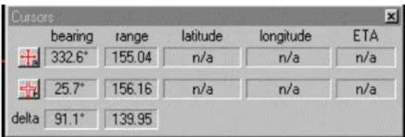
The Cursors Icon is used to enable the cursor 1, and cursor 2, when you activate the Cursors Icon a dialogue window will be displayed on the sonar image.
3.5 TOOL BAR ACCESSORIES

In addition we have incorporated additional Icon tools, i.e. Tape measure, Text Wiper, Catch Sensors, Display Sector Up and Down, Polar, Sounder, Net Opening and Magnifier,

The last two Icons on the Tool Bar are dedicated to set up your sonar picture. The first one will tile the Windows automatically in a vertical mode. The last Icon "H" will align the sonar picture in the center of the display screen and set it up in a High/Low resolution mode.
3.6 CATCH SENSOR

The Catch Sensor window will be displayed automatically when you click on the "S" Icon located on the Tool bar. To activate or de-activate individual Catch Sensor, you must go to the "Display" menu and select the "Head Sensor" and Click on the "ON/OFF" button. The Catch Windows may be displayed Vertically or Horizontally.
3.7 DEPTH AND TEMPERATURE GRAPHS
To activate the Depth or the Temperature graphs you must click on the "VIEW" menu button, move the mouse pointer to the "Display" and click, than go to "SHOW" and click, than click on the Depth Graph or the Temp Graph and the selected Graph window will pup up.
3.8 LANGUAGE
The FS 20/25 will provide at a later date translation in: Norwegian, Icelandic, Russian, Spanish, Danish, Japanese; additional languages may also be provided if requested.
3.9 HEADER MENU STRUCTURE
When you have the sonar display set on Full Screen, tool bar, Image control bar, and status bar check in the OFF position, the only mean of operating the sonar will be by using the Header Menu.
The following chapters will describe each section of the Header menu structure.
When you CLICK the mouse on any Header menu a window will appear including a dialogue box. Just Click on any window or dialogue text you would like to activate.
3.10 FILE
Close fused data (NOT USED)
Show Depth Graph
Temp Graph
Overload Counter
Display Settings Colors
Controls
Head Sensors
Clear Display
Delete all Markers
FS Catch Sensors Vertical
Horizontal
Customize New User Display
MESSAGE LOG Active
Visible
Clear
Sensors "NMEA" DATA NMEA L/L Window
PLAYBACK PROGRESS
EVENTS LOG FILE Read Event Log File
SONAR TOOLBAR Click ON/OFF
CHART TOOL BAR (NOT USED)
MARKERS TOOLBAR (NOT USED)
IMAGE CONTROL BAR Click ON/OFF
Show
Hide
Auto Hidden
STATUS BAR Click ON/OFF
FULL SCREEN Click ON/OFF
SCREEN FIT IMAGE Click ON/OFF
3.12 CONFIGURATION
CONNECT HEAD My Computer
COM 1 FS 20
COM 2 FS25 or
DGPS IN/OUT
OFFSETS (NOT USED)
SENSORS "NMEA" DATA COM Port Selection
User Defined
PARAMETERS Unit's
Feet's
Yard's
Meter's
Fathom's
Sound Speed Temp
Salinity
Depth
Magnetic Variation E or W
OPTIONS (NOT USED)
CALIBRATE HEAD POSITION Input the L/L of the Sonar Head
USER Generic
User 1
Define
SAVE SETTINGS Save user define setting
LOAD SETTINGS User define setting
3.13 OPERATIONS
RUN SONAR HEAD
STOP SONAR HEAD
SELECT SONAR HEAD
FS 20
FS 25
CONTROL SONAR HEAD Scan
Transmit
Info
TVG Page
PAUSE SONAR HEAD FS 20
FS 25
SCAN REVERSE FS 20
FS 25
RECORD DATA
PAUSE RECORD
END RECORD
EXPORT DATA
PAUSE EXPORT
END EXPORT
PLAYBACK DATA Begin Playback
Pause
EVENTS (NOT USED)
SYNCHRONIZE FS 20
FS 25
FACTORY RESET
3.14 TARGETS
ARROW
CURSOR 1
CURSOR 2
TAPE MEASURE
HEIGHT MEASURE
STRING MEASURE
TEXT
WIPER
3.15 NETWORK
CONNECT TO SERVER Connect Remote Work Station Setup
CONNECT TO CLIENT
SEE PART 7 "ATTACHEMENTS" FOR SYSTEM SET-UP
3.16 WINDOW
NEXT
PRECIOUS
CASCADE
TIDE HORRIZONTALLY
TIDE VERTICALY
ARRANGE ICONS
1 FS 20 XDCR DOWN or Disconnected FS 20
2 FS 25 XDCR DOWN or Disconnected FS 25
3.17 HELP
HELP TOPICS
ABOUT
3.18 INSTALLATION & SET UP
The FS 20/25 installation, system set up configuration and test will be covered in PART 4 of this manual.
PART 4
FS 20/25 INSTALLATION, SYSTEM SET-UP AND TEST
4. FS 20/25 INSTALLATION, SYSTEM SET-UP AND TEST ....4.3
4.1 INSTALLATION PROCEDURE....4.3
4.2 SURFACE UNIT ELECTRONICS INSTALLATION....4.3
4.2.1 Mounting of Units....4.3
4.2.2 Power Considerations....4.4
4.2.3 Connecting a Display Unit....4.4
4.2.4 Connecting the Processor....4.5
4.2.5 FS 20 System Installation Procedure....4.5
4.2.6 FS 20/25 System Installation Procedure....4.5
4.2.7 Connecting the ITM Module 4.7
4.2.8 Selecting AC Supply Voltage 4.7
4.2.9 Selecting the Trawl Output Voltage....4.7
4.2.10 Connection to Cable Winch/Slip-Rings....4.8
4.2.11 Interfacing to a Simrad Echo Sounder 4.8
4.3 ASSEMBLING OF TRAWL UNIT 4.9
4.3.1 FS 20/25 Configuration....4.9
4.4 SYSTEM SET-UP AND TESTING USING TEST CABLE 4.10
4.4.1 Start Up 4.10
4.4.2 Power-Up Configuration....4.11
4.4.3 FS 20Start-up Procedure....4.11
4.4.4 FS 20/25 Start-up Procedure 4.14
4.4.5 FS 20 or FS 20/25 RUN UP Procedure....4.19
4.4.6 Display Settings....4.20
4.4.7 Control Setting....4.21
4.4.8 Head Sensors Setting....4.22
4.4.9 FS 20 Head Setting....4.23
4.4.10 Transmit Setting....4.24
4.4.11 TVG Page Setting 4.25
4.4.12 Info 4.26
4.4.13 Auxiliary Transducer (Net Sounder)....4.27
4.4.14 Auxiliary TVG Page Setting ( Net Sounder)......4.28
4.4.15 FS 25 Head Settings 4.29
4.4.16 Save User Setting 4.30
4.4.17 Final System Test....4.32
4.4.18 Completing Trawl Unit Assembly....4.32
4.4.19 Mounting CATCH SENSORS....4.33
4.5 SAVE USER SETTING....4.34
4. FS 20/25 INSTALLATION, SYSTEM SET-UP AND TEST
4.1 INSTALLATION PROCEDURE
The installation of the FS 20/25 Trawl Monitoring System involves the following steps:
- Deciding on the locations in the wheel house for the surface units.
- Mounting the surface units and making the connections between the FS 20/25 HP PC Processor, the display unit, the FS 20/25 Power Supply/TTM interface unit, and other optional equipment being installed.
- Assembling the trawl unit.
- Running up the system on the test cable to verify proper installation, configure control unit, and perform initial system test.
- Installing the cable winch, snatch block and trawl cable, and connecting the winch slip-rings to the control unit.
- Mounting the trawl unit to the headrope and completing the final system test.
- Mounting the catch sensors to the cod-end of the trawl.
4.2 SURFACE UNIT ELECTRONICS INSTALLATION
4.2.1 Mounting of Units
The display unit should be located in the wheel house in a place that provides a good view of the screen and avoids direct sunlight, if possible. Depending on the monitor that was selected, the unit may be mounted on top or recessed into the bridge console. Simrad supplied display units include the necessary mounting brackets.
The FS 20/25 HP PC processor should be mounted in close vicinity to the operator's position in the wheel house and near the display unit. The unit may be mounted below or recessed into a cabinet. Note: You must have access to the ON/OFF switch.
The Power Supply/TTM interface module supplied with the system may be mounted on top of the bridge console or recessed and flush mounted into the bridge console. Sufficient space should be left around the control unit for proper ventilation.
Optional equipment for interface to the control unit may be mounted in any convenient location provided the user supplied interconnect cables are of sufficient length and the required power is available.
4.2.2 Power Considerations
The display unit, generally, will require 110 VAC or 220 VAC. Depending on the capabilities of the unit chosen, it may automatically detect the supply voltage or the unit may have to be ordered for the correct voltage.
The FS 20/25 HP PC processor will operate from either 110 VAC or 220 VAC. Voltage selection must be selected, a voltage input selector switch is located at the rear of the unit. Failure to select the proper Input voltage will damage the internal power supply
The FS 20/25 Power Supply/TTM module can be operated with either 110 VAC or 220 VAC. Selection of the supply voltage is done by moving the voltage selector card located in the power entry module at the rear panel. Details on selecting the proper voltage are indicated on the voltage card. You must position the "indicator pin" location to the desired voltage. The safety fuses must also be changed to the proper rating. Refer to Paragraph 4.2.7 for more detail.
4.2.3 Connecting a Display Unit
Either a VGA monitor CRT type or a Simrad LCD monitor may be connected to the FS 20/25 HP PC processor. Depending on which type of monitor is used, the video output type must be set accordingly.
An industry standard VGA monitor will connect directly to the miniature DB-15 connector located on the rear panel of the control unit.
The FS20/25 HP PC has a DualHead video interface card installed as standard equipment. You must set up your display software as per your requirement. If you have only one monitor, simply plug your monitor cable into the monitor connector marked "Connector 1" on the adapter card, or Video "A" port. If you are using two monitors, you must connect the 2^nd monitor in the "Connector 2" on the adapter card, or Video "B" port.
Note: The FS20/25 HP PC must be is turned “OFF” prior connecting the video monitors
An HP User Guide manual is provided with the system, including a Recovery CD-ROM. With this CD you can recover your system as delivered, run HP diagnostics. Note: The DualHead software is installed at the factory, you only have to set up your monitor configuration as per Window's 2000. See Part 7 "Attachment" for set-up
procedure.
4.2.4 Connecting the Processor
The FS 20/25 HP PC Processor unit comes with the FS 20/25 Trawl Sonar System operating software installed by the factory.
Note!
All Device driver and HP utilities are preloaded on your system and provided on a Driver, Utilities and documentation CD-ROM. This CD-ROM also includes tips for re-installing the operating system.
Mount the FS processing unit with easily accessible power outlet and enough space for the display, keyboard, mouse, printer, TTM module, and any other accessories. The connectors are shaped to go in one way only.
4.2.5 FS 20 System Installation Procedure
For Vertical Head, Net Sounder Option and Sensor Module:
Connect the RS 232 Port "A" serial cable from the Power Supply/TTM module to the serial "A" port at the rear of the processing unit. A standard Null Modem 9-pin serial cable is supplied with the TTM module.
Connect the DGPS NMEA 183 output to the serial "B" port at the rear of the processing unit. Interconnect cable not supplied.
The pin connections for your DGPS input/output PC/RS232 are as follows:
Pin number "2" 232 Rx, Pin number "3" 232 Tx, and Pin number "5" GND.
Connect the security key “Dongle” to the parallel port. If you require connecting a printer in the parallel port, just plug your printer into the “Dongle”.
4.2.6 FS 20/25 System Installation Procedure
For Vertical Head, Net Sounder Option, Sensor Module and Horizontal Sonar Head.
Connect the RS 232 port "A" serial cable from the Power Supply/TTM module to the serial "A" port at the rear of the processing unit. A standard Null Modem 9-pin serial cable is supplied with the TTM module.
Connect the RS 232 port "B" serial cable from the Power Supply/TTM module to the
serial "B" port at the rear of the processing unit. A standard 9-pin serial cable is supplied with the TTM module.
If you require connecting a DGPS NMEA 183 output to the serial port at the rear of the processing unit, you will have to install an addition serial card in the HP PC Processing units. The recommended type of serial card to install and the installation procedure are provided in Part 7 "Attachments". Interconnect cable not supplied.
The pin connections for your DGPS input/output PC/RS232 are as follows:
Pin number "2" 232 Rx, Pin number "3" 232 Tx, and Pin number "5" GND.
Connect the security key "Dongle" to the parallel port. If you require connecting a printer in the parallel port, just plug your printer into the "Dongle".
Your FS 20/25 comes equipped with a Network LAN interface adapter card. The LAN adapter supports both 10Mbit/s and 100Mbit/s operations and automatically detects which network type is being used. The RJ-45 plugs into your FS 20/25 optional remote workstation. LAN cables are not supplied with the system.
For additional information, please refer to the User's Guide supplied with the system.
Warning!
Before applying the power to the processing unit, ensure that the proper AC input voltage has been selected.
4.2.7 Connecting the TTM Module
The TTM interface module comes with the long line power supply incorporated in one unit, thus making the installation easier.
The Front Panel comes with an ON/Off switch, trawl DC output voltage meter and amperage meter, and a four position trawl voltage rotary selection switch is provided. The possible selections are; "OFF", "TEST", "FS20", "FS25".
The Rear Panel of the TTM module comes with the AC 110/220 power input, master ON/OFF switch and fuse located in the AC power entry module, an RS232 serial port "A" and "B", an RS485 serial port "A" and "B" and the 3^rd wire trawl cable connector. Note: To connect the TEST cable, just disconnect your 3^rd wire trawl cable.
4.2.8 Selecting AC Supply Voltage
You must select and position the line voltage card located inside the power entry module to the desired position.
To change the input line voltage, use a small blade screwdriver and pop the cover. Pull the voltage selector card straight out from the housing, and place the indicator pin to the selected desired voltage. Reinsert the card, reinstall the cover and verify that the indicator shows the desired voltage. You must insure that the proper fuse rating is installed, 2 Amp for 220Vac and 4 Amp for 110Vac. Spare fuses are supplied with the TTM module
4.2.9 Selecting the Trawl Output Voltage
You must select the proper trawl voltage in accordance with the under water trawl unit system you are using, FS20 or FS20/25 trawl.
A- In the "OFF" position, no voltage is applied to the trawl cable.
B- In the "TEST" position, 60 VDC will be provided to the trawl cable. Note: In the "TEST" position you must connect the test cable supplied with the system in lieu of the trawl cable at the rear of the TTM module.
C- In the "FS20" position, 120 VDC will be provided to the trawl cable. You select the FS 20 when you have an FS900 Housing under water unit connected to the trawl cable, utilizing an FS3300, TS10, TS15 or TS15S sonar head and a sensor module.
D- In the "FS25" position, 200 VDC will be provided to the trawl cable. You select the FS25 position when you have a FS900/FS925 Housing under water unit connected to the trawl cable, utilizing a FS925 forward-looking sonar head and an FS3300, TS10, TS15, or TS15S sonar head and a sensor module.
Note!
To test the FS25 trawl sonar heads connected to the test cable, you will have to position the voltage selection to FS20.
Warning!
. If you connect an FS3300 330kHz or 120kHz sonar head to the trawl cable with the switch set to FS25, 200 VDC, you will damage your trawl sonar head. The FS25, 200VDC, will be used with an FS 925 90kHz Stand Alone Sonar Head, or a full FS900/925 Deployment Package with any combination of Vertical Heads (FS3300, TS10,TS15 or TS15S) connected to the trawl cable.
4.2.10 Connection to Cable Winch/Slip-Rings
The connection between the FS 20/25 TTM Interface unit and the cable winch/slip-rings should be made with an 18 GA., or heavier, shielded twisted pair cable. The connection to the control unit is made using the 3-pin MS connector supplied in the TTM module accessory kit. To minimize noise interference on the cable, the shield of the cable should be attached to the connector.
Note!
The shield of the cable between the FS 20/25 TTM module and the slip-rings should be connected at the TTM module, but NOT at the slip-rings.
4.2.11 Interfacing to a Simrad Echo Sounder
The FS 20/25 HP PC processor may be connected to a Simrad echo sounder for display of the trawl unit depth on the sounder. This is made via the RS232 serial port "B" on the rear panel of the control unit (DB-9 connector labeled "RS-232" "B" port). The processor will output the Temperature and the Depth from the trawl sensor module in an NMEA 0183 format.
If the port "B" is not available, you will have to install an additional serial card. The recommended type of serial card to install and the installation procedure are provided in Part 7 "Attachments". Interconnect cable not supplied.
4.3 ASSEMBLING OF TRAWL UNIT
Assembling the trawl unit for the first time should be conducted in the wheel house where the surface unit electronics have been mounted. This will facilitate testing the trawl unit using the test cable.
4.3.1 FS 20/25 Configuration
The FS 20 trawl configurations all consist of an FS3300, or TS10, or TS15, or a TS 15S sonar head, an FS 3300 sensor module and the FS900 polyurethane housing. The FS 20/25 will have an additional FS925 sonar head, an FS 900/925 polyurethane housing, mounting and assembling hardware, and a strain relief. The trawl unit also contains a catch receiver unit. Assembly of the unit involves correctly locating the sonar head, attaching strain relief to trawl cable, proper routing and connection of cable to the sonar head and bolting the polyurethane housing together. This section describes the connection and locating of the sonar head, the sensor module and catch receive transducer; final assembly is illustrated in Part 6 "Drawings".
The FS sonar heads should have been supplied from the factory with two retaining rings (collars) and a locating pin or guide bracket already installed. If not, these parts will be included with the sonar head and should now be attached.
A stainless steel locating pin threaded into one the tapped holes located in the connector end of the housing or a guide bracket is used to prevent the sonar head from rotating. Only one pin is required and it can be placed into the positioning hole, as shown in the assembly drawing in Chapter 6, of the bottom half of the trawl unit housing. The pin location should be such that the diaphragm housing that protrudes from the sonar head housing will be located to one side (normal convention has polyurethane housing half with metal serial number plate being used as the top). Correct location of the pin will be determined during initial test of the system.
The first retaining ring is mounted on the sonar head housing flush with the transducer end of the housing, and the second retainer ring is mounted approximately 25 mm/1" from the first. Final position (see Chapter 6 - Drawings) is determined by placing the sonar head into one half of the trawl unit housing with the locating pin inserted into the correct hole. The first retaining ring is then moved in tight against the outside of the polyurethane housing and the second retaining ring is moved in tight against the inside of the polyurethane housing outside wall. Both are fastened into place to prevent the sonar head from moving back and forth.
Note!
Incorrect placement of the retaining rings and locating pin or the guide bracket on the sonar head, or the failure to install these parts, may result in movement of the sonar head that could damage the transducer and/or drive shaft and result in water damage to the entire unit.
Liberal amounts of Dow Corning #55 grease should be applied to all connector surfaces before mating so that a water tight seal is obtained. The locking sleeve should then be hand-tightened.
Note
Dow Corning #55 grease must be applied to all mating surfaces of underwater connectors to insure proper sealing. Sufficient grease should be applied so that excess squeezes out with any air when the connectors are mated. RTV or any other sealant must NOT be used, and when tightening the locking sleeves, do NOT use a wrench or pliers! See chapter 5, "Troubleshooting and Maintenance", for proper connector maintenance.
4.4 SYSTEM SET-UP AND TESTING USING TEST CABLE
Initial power-up, set-up and test of system should be made with the trawl unit, in the wheel house, connected to the PWR/TTM module using the supplied test cable. The 3-pin MS connector of the test cable is attached to the connector labelled "Trawl Cable" on the rear panel of the PWR/TTM unit. The other end of the test cable is plugged into the 2-pin connector on the sonar head of the trawl unit.
4.4.1 Start Up
- Check that the system has been properly installed and that all connections have been made to the PWR/TTM, and the HP/PC processing unit.
- First turn on the PWR/TTM interface module. The voltmeter should display approximately 112 volts if on "FS 20" setting, 200 volts if on "FS 25": setting and approximately 56 volts if on "TEST" setting. The current meter should read approximately 0.15 – 0.7 amps if everything is okay.
- Next turn on the display monitor, and then turn on the HP/PC. The system will start up automatically.
4.4.2 Power-Up Configuration
For the system to operate properly, the trawl unit configuration must be selected correctly. In addition, modification of these power-up configuration parameters is done in a special mode selected after power-up of the HP/PC processor unit.
The following sections describe the process of configuring these parameters. These steps must be followed only when the system is powered-up for the first time or when you have to replace the HP/PC processing unit or the TTM Module assembly.
4.4.3 FS 20Start-up Procedure
For the purpose and demonstration on the Start-up Procedure in this chapter, we are using an HP/PC processing unit that has only 2 Com ports, Com 1 and Com 2. The Com 1 port from the HP/PC processing unit is connected to the FS20/25 TTM module RS 232 port "A". No connection is made to the Com 2 or to the "B" port of the TTM module.
We will be using a TS15 S 330kHz Trawl Sonar Head with the 200kHz net sounder option and an FS3300 sensor module.
The first step after a successful power up is to configure the system for the desired "User Setting" operating mode and set-up, if not already done; you will automatically select "Generic". Clicking on "Generic" or clicking on specific types of fishery does this. Refer to the following window.

Configuring the System for the first time, or if you have replaced the HP/PC processing unit or the TTM Module, you will select and "Click" on "Generic" and then "Click" on OK.
The next Window will pop up
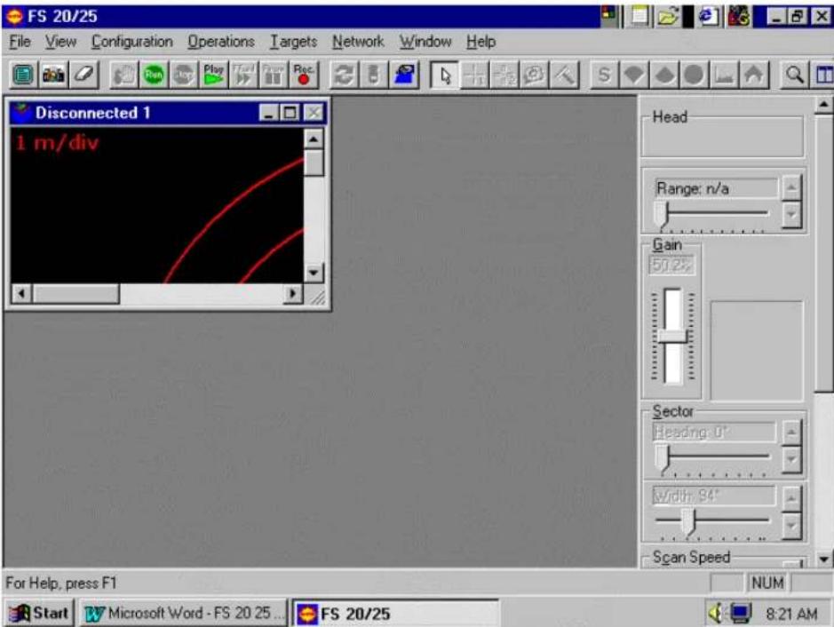
Go to the header menu, "Click" on "Configuration" and a dialogue window will pop up. Next "Click" on "Connect Heads". The following window will pop up.
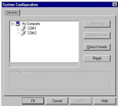
After the "System Configuration" Window pops up, note that Com 1 has not been
enabled yet (no red check mark beside Com 1). If you "Click" on "Detect Heads" from this position, the following warning window will pop up.
This warning window indicates that "No Ports have been enabled"; just "Click" "OK".

The "System Configuration" window will reappear. Use the mouse to highlight COM 1. Note that the COM 1 Configuration will now be displayed. Use the mouse to "Enable for Head Control" (Left button click, check mark in box to enable).

"Click" on "Apply". The following window will appear, overlaying the above window, asking you to reboot the computer. Just "Click" "OK" (the "FS 20/25" window will disappear) and do not "Reboot the computer now"; "Click" "OK" in the "System Configuration" window.

Now you will have to go to the Header Menu, "Click" on "Configuration" and a dialogue window will pop up. "Click" on "Connect Heads".
The "System Configuration" window will pop up. "Click" on "Detect Heads"

Then "Click" on "Apply" next "Click" "OK". From the Operating System window, "Click" on the "RUN" Icon to start the System.
4.4.4 FS 20/25 Start-up Procedure
For the purpose and demonstration on the Start-up Procedure in this chapter, we are using an HP/PC processing unit that has only 2 COM ports, COM 1 and COM 2. The COM 1 port from the HP/PC processing unit is connected to the FS20/25 TTM module RS 232 port "A". The COM 2 port from the HP/PC processing unit is connected to the FS20/25 TTM module RS 232 port "B"
We will be using a TS15 S 330kHz Trawl Sonar Head with the 200kHz net sounder option and an FS3300 sensor module and the FS925 forward-looking sonar head.
The first step after a successful power up is to configure the system for the desired "User Setting" operating mode and set-up, if not already done; you will automatically select "Generic". Clicking on "Generic" or clicking on specific types of fishery does this.
Refer to the following window.
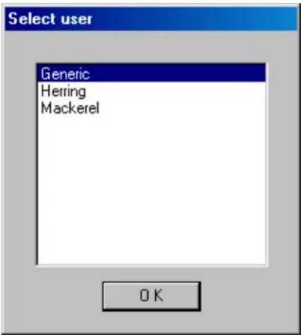
Configuring the System for the first time, or if you have replaced the HP/PC processing unit or the TTM Module, you will select and "Click" on "Generic" and then "Click" on OK.
The next Window will pop up
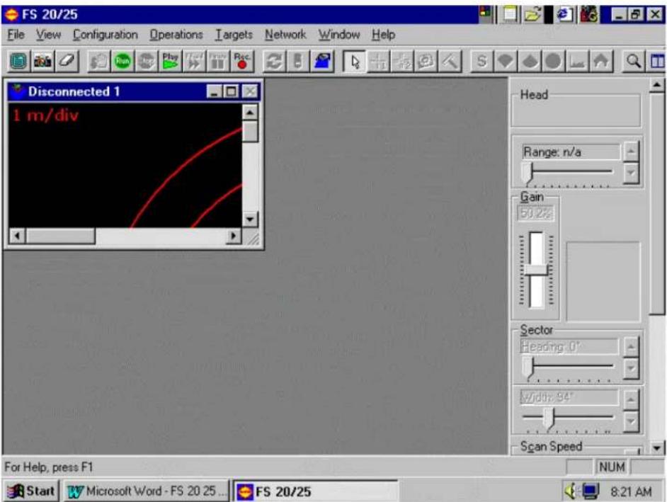
Go to the header menu, "Click" on "Configuration" and a dialogue window will pop up. Next "Click" on "Connect Heads". The following window will pop up.
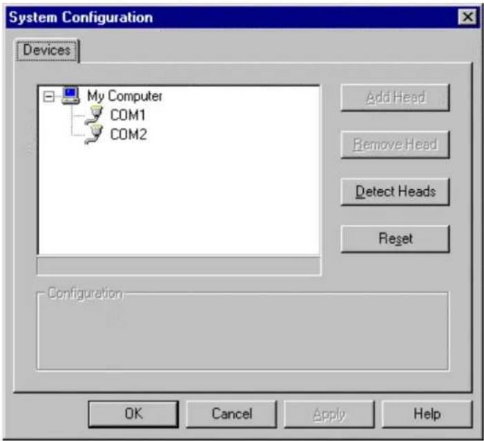
After the "System Configuration" Window pops up, note that COM 1 and COM 2 have not been enabled yet (no red check mark beside COM 1 and COM 2). If you Click on "Detect Heads" from this position, the following warning window will pop up.
This warning window indicates that "No Ports have been enabled"; just "Click" "OK".

The “System Configuration” window will reappear. Use the mouse to highlight COM 1. Note that the COM 1 Configuration will now be displayed. Use the mouse to “Enable for Head Control” (Left button click, check mark in box to enable).
Repeat the same operation for the COM 2.

"Click" on "Apply". The following window will appear, overlaying the above window, asking you to reboot the computer. Just "Click" "OK" (the "FS 20/25" window will disappear) and do not "Reboot the computer now"; "Click" "OK" in the "System Configuration" window.
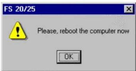
Now you will have to go to the Header Menu, "Click" on "Configuration" a dialogue window will pop up. "Click" on "Connect Heads".
The "System Configuration" window will pop up. "Click" on "Detect Heads"

"Click" on "Apply" next "Click" "OK". From the Operating System window, "Click" on the "RUN" Icon to start the System.
In the event that part of the system gets changed out with a new component (i.e. a different TTM, a change in software, etc), you might find that the Sonar Head Confirmation window might appear. It will ask you if you want to reconfigure "Click" on "NO", then go back to the "Header Menu" "Click" on "Configuration" and re-start the system set-up as per outline in Paragraph "4.4.3" or "4.4.4".

4.4.5 FS 20 or FS 20/25 RUN UP Procedure
After you "Click" on the "RUN" Icon, the system will automatically detect and setup the sonar heads attached to the trawl cable. This operation will take approx. 40 sec.
After the system RUN UP is completed, the best way to setup your windows is to "Click" on the Tool Bar "Tile Windows" Icon located to the right end side of the Tool Bar. By clicking on the individual window, you can rearrange, change the size, as you prefer, etc.
Refer to the following window

From that point on by clicking on the "FS 20", TS 15 Sounder or the FS 25 window you will have control over the selected Sonar. The sonar you have selected will be highlighted by a blue bar across the top..
4.4.6 Display Settings
Position the cursor on the "DISPLAY SETTINGS" Icon, (the one next to the small sonar head located on the TOOL BAR), and CLICK. The following window below will pop up.
By selecting the appropriate "KEY", you will able to setup your Colors, Controls Setting and the Head Sensors.
![Display Settings - FS 20 Colors | Controls | Head Sensors | Primary Overlay Colors Sector Limit Profile Points Grid Cursor 1 Cursor 2 Annotation Colors on Second Head Sector Limit Profile Points Palette Styles Simrad [2] Palette Threshold [ 0 ] OK Cancel Apply Help](/content/2026/05/963811/images/3a4a6061539544f43abedc64a8b13ea107cea8a65aafa0f8a98c46d7a2337124.jpg)
By clicking on the appropriate "key" you will be able to change the color i.e. Overlay colors, Pallets styles and threshold, etc.
The same operation will apply to the TS15 S sounder, and the FS25 windows
4.4.7 Control Setting
By selecting and clicking on the "Control" key on the above window, the following window will pop up.

By clicking on the appropriate key, you will be able to setup your control setting, i.e. gain control, RX gain, scan maker, etc.
Note: The "Timer Control" will be turn "ON" automatically when you CLICK on the "S" Icon located on the "Tool Bar".
The same operation will apply to the TS 15 S sounder and the FS 25 windows
4.4.8 Head Sensors Setting
By selecting and clicking on the "Head Sensors" key on the above window, the following window will pop up.
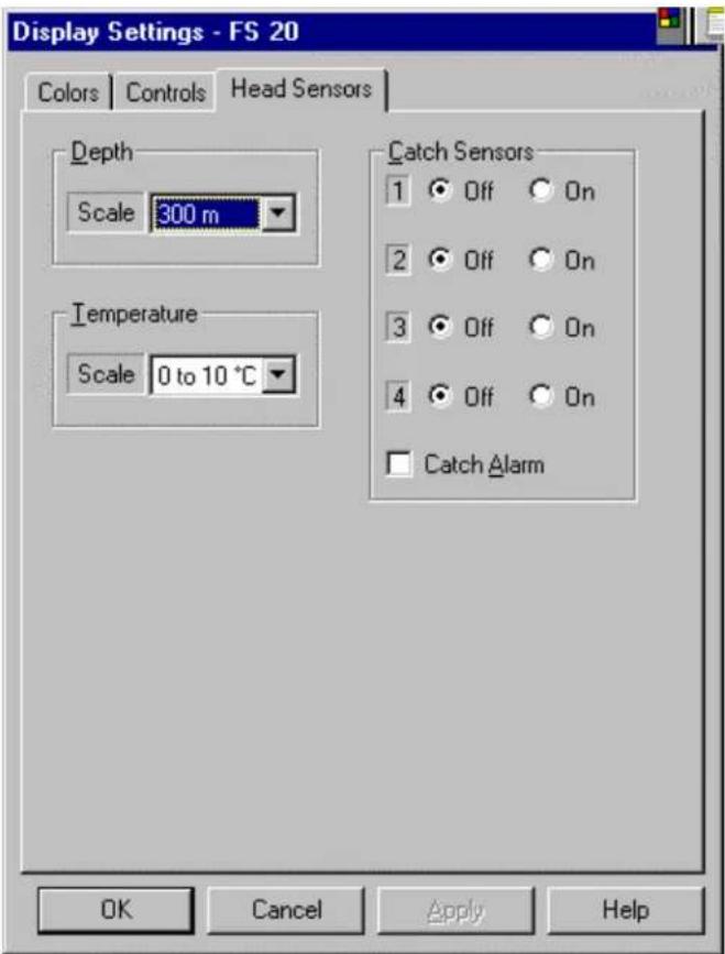
By clicking on the appropriate key, you will be turning the catch sensor ON or OFF. The Depth and temperature can also be changed.
Note: The "Heads Sensors" will be turn "ON" automatically when you CLICK on the "S" Icon located on the "Tool Bar". You can turn "ON" or "OFF" the catch Sensors individually if required.
The "Catch Alarm" may be turn "ON" or "OFF" using this menu by clicking in the appropriate check box.
The same operation will apply to the TS 15 S sounder.
Note: The Catch, Depth and Temp will not apply to the FS 25 window.
4.4.9 FS 20 Head Setting
Position the cursor on the "CONTROL HEAD" key, (The one with the small sonar head located on the TOOL BAR) and CLICK. The following window below will pop up.

By clicking on the appropriate "KEY", you will be able to setup your Scan option. You also have full control of the Scan mode via the operator control panel.
Mote: The "Tilt" and "Stabilization" is only available on the FS25 System.
4.4.10 Transmit Setting
By selecting and clicking on the "Transmit" key on the above window, the following window will pop up.

By clicking on the appropriate key, you will be able to setup your Transmitter configuration in order to optimize fish detection.
The same operation will apply to the TS 15 S sounder and the FS 25 Windows
4.4.11 TVG Page Setting
By selecting and clicking on the "TVG Page" key on the above window, the following window will pop up.

By clicking on the appropriate key, you will be able to setup your TVG setting. You also have the option of customizing your TVG setting for a specific fishery.
The same operation will apply to the TS 15 S Sounder and the FS 25 windows.
4.4.12 Info
By selecting and clicking on the "INFO" key on the above window, the following window will pop up.

This INFO page will provide you with all the relevant information on the sonar head attached to the system.
The same window will apply to the FS 25 System
4.4.13 Auxiliary Transducer (Net Sounder)
By Clicking on the "Auxiliary Transducer" key on the above window, the following window will pop up.

By Clicking on the appropriate key, you will be able to control the TS 15 S sounder option.
Note: The Auxiliary Transducer window is only applicable to the TS 15 S Sounder option.
4.4.14 Auxiliary TVG Page Setting (Net Sounder)
By selecting and clicking on the "Aux. Head TVG" on the above window, the following window will pop up

By Clicking on the appropriate key, you will be able to setup your TVG setting. You also have the option of customizing your TVG setting for a specific fishery.
Note: The Auxiliary TVG window is only applicable to the Ts 15 S sounder option.
4.4.15 FS 25 Head Settings
By clicking on the FS 25 window and position the cursor on the "Control Head" Key, (the one with the small sonar head located on the TOOL Bar) and Click. The following window will pop up.

By Clicking on the appropriate "Key", you will be able to setup you Scan, Transmit, cull up your Info page and setup your TVG the same way you setup the FS 20 Sonar head
Note: The FS25 Head Setting window is specific to the FS 925 Trawl Sonar head and does not have the Sensors, Auxiliary Transducer and Auxiliary TVG settings.
4.4.16 Save User Setting
After you have completed your system configuration, you should save your setting, Go to the Header Menu and CLICK on "Configuration". Next CLICK on "USERS", then CLICK on "DEFINE". The following window will pop up.
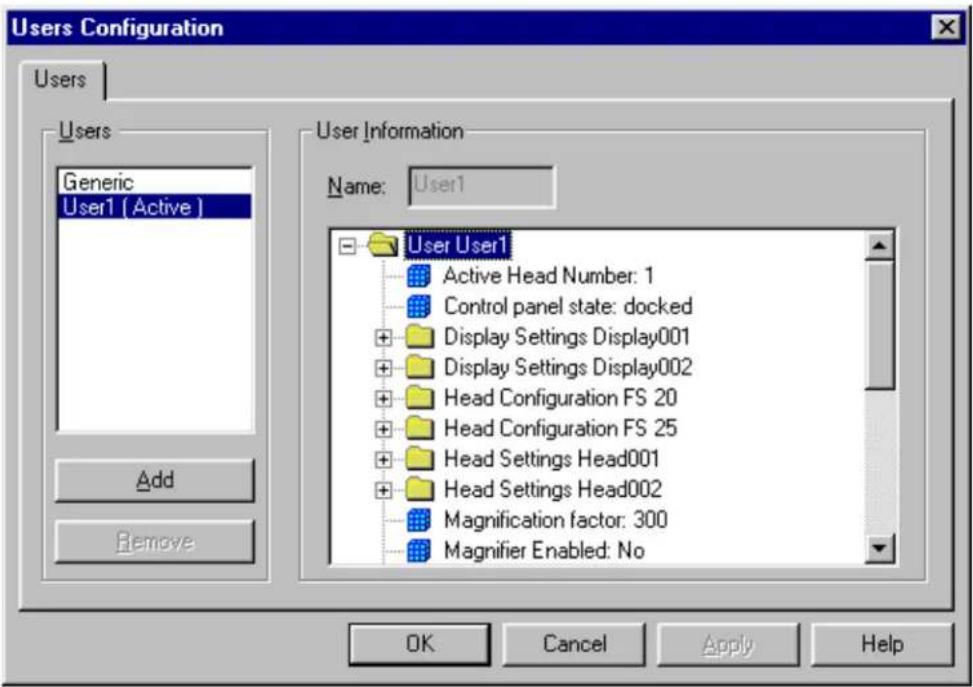
The next step, if you want to Add a User, CLICK on "Add", then type your name in the User 1 window. Next CLICK on "Apply" then "OK".
The next time you start up the system, the "Select User" window will pop up automatically, then you must select the type of Fishery or User setting you want to select and "CLICK". The system will start up with your personal setting.
When you Exit the system, the system will request if you want to save your setting. Just say "YES" or "NO"
Note: After the Service Engineer has completed the initial Setup and Seatrial, we
recommend that all the setting be save in the "GENERIC" setting or in a specific file created as a reference in case a problem accurate.
Do not change the "GENERIC" setting. If you have a problem, just go back and select the "GENERIC" setting, or to your specific file.
4.4.17 Final System Test
After preparing the trawl cable and before final trawl unit assembly, a system test should be conducted to insure correct operation of FS 20/25 Trawl Monitoring System over the trawl cable.
As before, the start up procedures should be followed to power up the system. Once the FS 20/25 has been turned on, the power supply voltage and current meters should be examined. Expected values are 0.2 – 0.5 (output voltage selection switch should be set to FS 20) or FS 25 if you have an FS 925 sonar connected. If the voltage and current values differ significantly from these values, it indicates a problem with the trawl cable or its connections.
If there are any errors during the calibration, a status report page will appear containing the results that the control unit obtained from tests performed. Again, any errors will be due to the trawl cable or its connections. Check the connections again and insure that the signal polarity at the trawl unit is correct. A DC voltmeter can be used to check that the positive voltage is on the small pin of the pigtail when the FS 20/25 PWR/TTM unit is powered up.
If all is okay, then the sonar image display will appear and the sonar head will begin scanning.
4.4.18 Completing Trawl Unit Assembly
The final step in the installation is to complete the trawl unit assembly and mount it to the headrope as shown on drawings in Chapter 7.
First, the plastic cable strain relief supplied with the trawl unit must be bolted to the trawl cable. The location should be at or very near the pigtail splice, but NOT on the pigtail itself. You must slide the rubber hose on the trawl cable, if used, down so that approximately 3-4 cm (1-2") of the hose is clamped inside the strain relief.
Next, the trawl cable is connected to the sonar head. Liberal amounts of Dow Corning #55 grease are applied to the connector surfaces before mating so that a water tight seal is obtained. The locking sleeve is then hand-tightened.
Note!
Dow Corning #55 grease must be applied to all mating surfaces of underwater connectors to insure proper sealing. Sufficient grease should be applied so that excess squeezes out with any air when the connectors are mated. RTV or any other sealant must NOT be used, and when tightening the locking sleeves do NOT use a wrench or pliers! See chapter 5, "Troubleshooting and Maintenance", for proper connector maintenance.
The plastic strain relief attached to the trawl cable is now placed in the trawl unit housing containing the electronics and the excess cable is routed in the housing as shown in Chapter 6 "Drawings". Care must be taken to insure that all cables within the trawl unit housing are properly placed to avoid being pinched and possibly damaged. The top half of the trawl unit housing is then placed on top and the unit is secured together with the bolts supplied. Finally, the dome is secured over the Vertical Sonar Head transducer with four additional bolts.
The fully assembled trawl unit is now ready for mounting to the trawl headrope in the chosen manner.
4.4.19 Mounting CATCH SENSORS
Proper mounting of the catch sensors on the cod-end is shown in drawing # 830-056482 (see chapter 6, "Drawings").
The fill of the cod-end and the sensitivity of the sensors is dependent upon the number of mesh knots between the catch sensor and the rubber straps. Make sure that the sensor is mounted in the correct direction with the transducer pointing towards the trawl unit (the metal lid pointing aft).
Caution!
Make sure that the chains do not strain the net when the cod-end is being filled with fish. This is controlled by stretching the net to capacity in the direction which is relevant AFTER THE SENSORS HAVE BEEN MOUNTED TO THE TRAWL.
The purpose of the chains is to prevent the sensor from turning, and as an insurance against loss should the rubber straps break. Mounting the chains too tight can result in the fastening ears being ripped off.
If a system with four catch sensors has been ordered, sensors numbered 1 and 2 can be used on the trawl and the other two sensors kept for reserve.
For deep trawling, and when fish is abundant, it can be advantageous to mount three or four catch indicators in such a way that cod-end filling can be monitored continuously to insure that the trawl is hauled back in time.
4.5 SAVE USER SETTING
After you have completed your system configuration, you should "SAVE" your setting. Go to the Header Menu and "Click" on "Configuration". Next "Click" on "USERS", then "Click" on "DEFINE". The following window will pop up.

The next step, if you want to Add a User, "Click on "Add", then type the name in the "User Information" window. Next "Click" on "Apply" then "Click" on "OK"
The next time you start up the system, the "Select User" window will pop up automatically. You must select the type of Fishery or User setting you want to run and "Click" "OK".
When you Exit the System from the "File" Header Menu, the system will request "Are you sure you want to exit?" "Click" on "Yes". Then the System will request "Do you want to save settings?" "Click" on "Yes" if it his new settings or "No" as you prefer. If you "Click" on "Yes" the following window will pop up.

From the following window, just "Click" on "OK" on the selected User that you have highlighted.
Note:
After the Service Engineer has completed the initial Setup and Seatrial, we recommend that all the settings are saved in the "Generic" setting. The operator can add a specific User file for the "Seatrial", as a reference, in case a problem occurs.
After the setup, do not change the "Generic" or your specific "Seatrial" setting. If you have a problem, just go back and select the "Generic" or your specific "Seatrial" setting.
PART 5
MAINTENANCE AND TROUBLESHOOTING
5. TROUBLESHOOTING AND MAINTENANCE....5.3
5.1 INTRODUCTION ....5.3
5.2 SYSTEM OVERVIEW....5.3
5.2.1 FS 20/25 System ....5.3
5.2.2 Trawl Cable Requirements....5.4
5.3 HANDLING & MAINTENANCE 5.4
5.3.1 Wheelhouse Electronics 5.4
5.3.2 Trawl Unit....5.5
5.3.2.1 Handling Tips....5.5
5.3.2.2 Maintenance Schedule....5.5
5.3.2.3 Connector Maintenance....5.6
5.3.2.4 Excessive Impacts....5.7
5.3.2.5 Corrosion....5.7
5.3.2.6 Shaft or Transducer Damage....5.7
5.3.3 Catch Sensors ....5.8
5.3.4 Winch Slip-Rings and Trawl Cable....5.8
5.4 MONITORING SYSTEM PERFORMANCE....5.9
5.4.1 Test Cable 5.9
5.4.2 Power Supply Meter Readings....5.10
5.4.3 Trawl Cable Gain 5.12
5.4.4 System Error Messages....5.13
5.5 TROUBLESHOOTING....5.15
5.5.1 System Tools....5.15
5.5.2 Diagnosing Problems....5.16
5.5.3 Common Fault Recognition Charts....5.17
5.5.3.1 PC to PWR/TTM Unit (Digital) 5.18
5.5.3.2 PWR/TTM Unit to Deployment Package Units (Analog) .....5.20
5.5.3.3 PWR/TTM Unit 5.22
5.5.3.4 Housing Units (Heads, Sensor Modules and Egg Receivers) .....5.23
5.5.3.5 Full 3^rd Wire Assembly (Including Slip Rings and Wheelhouse Cable)5.2p
5.6 SECTION 1 - CATCH SENSORS ....5.27
5.7 SECTION 2 - WINCH SLIP RINGS AND TRAWL CABLE .....5.27
5. TROUBLESHOOTING AND MAINTENANCE
5.1 INTRODUCTION
This document is intended to provide a minimum level of instructions for the proper handling, maintenance and troubleshooting of the FS Trawl Monitoring System. The information is applicable to both the FS 20 and FS 20/25 systems.
5.2 SYSTEM OVERVIEW
The Simrad FS Trawl Monitoring System (both FS 20 and FS20/25 consists of wheelhouse electronics and a trawl unit. The wheelhouse electronics include the display unit, the FS 20/25 HP PC processing unit, and the PWR/TTM interface unit. The trawl unit electronics includes the sonar head, sensor module, catch receiver and up to four catch sensors. In addition to the above equipment, but not supplied by Simrad, the system requires a winch with slip rings, and a trawl cable for connection of the FS trawl unit to the wheelhouse electronics.
The system configurations for FS 20 and FS 20/25 are similar, but there are some important differences. These differences are discussed in the following sections.
5.2.1 FS 20/25 System
The FS 20/25 PWR/TTM unit contains the Power Supply Module to provide the 60,120 or 200 Vdc @ 1A maximum for powering the trawl unit electronics, by means of a rotary switch; voltage supplied and current draw are displayed on the front panel voltage and ampere meters. The PWR/TTM unit also contains the Low-Frequency Telemetry Adapter Sub-assemblies, "LF 1" and "LF 2". For an FS20 system there would only be an LF1 Sub-assembly installed; an FS20/25 would have both. These Sub-assemblies serve a dual role; they are part of a "digital" link to establish communication with the PC via the COM Port(s), as well as the direct "analog" link to the Trawl Head via the 3^rd wire (or test cable).
With the either the FS 20 or the FS 20/25 systems, the trawl cable connects directly to the PWR/TTM unit rear panel. The COM Ports for the PC link are also on the rear panel
5.2.2 Trawl Cable Requirements
For whatever cable type and length used, the following specifications must be met for operation with the Simrad FS Trawl Monitoring system:
Cable Closed Loop Resistance: <100Ω
Signal Attenuation Through Cable: <40 dB (1/100 signal amplitude) @ 55 kHz
<20 dB (1/10 signal amplitude) @ 12 kHz
The cable closed loop resistance determines the maximum voltage drop along the trawl cable. For proper operation, the trawl unit electronics require 55 - 140 Vdc @ 1A maximum. For typical operation, the current is approximately 300mA with peaks to 500mA.
Compensation for signal losses over the long trawl cable is done automatically within the HP/PC processor unit each time it is powered up. In this way, changes to the cable losses do not affect the intensity of the sonar return displayed.
5.3 HANDLING & MAINTENANCE
The most common causes of failures to the Simrad FS Trawl Monitoring system are:
- Trawl cable and/or winch slip ring problems.
- Sonar head and sensor module connector and interconnect cable failures, or
- Excessive impacts and/or physical damage to trawl unit electronics.
In all three of these cases, proper handling and maintenance can significantly reduce the frequency of FS failures.
The following sections outline the recommended handling and maintenance for the FS system.
5.3.1 Wheelhouse Electronics
Once installed, these units require little maintenance other than removing dust. A damp, lint-free cloth should be used for this purpose. Note also that it is absolutely essential that these units are receiving proper ventilation, particularly if the boat is operating in warm climate locations.
5.3.2 Trawl Unit
The Trawl Unit is subjected to the harshest conditions, and therefore proper handling and maintenance is crucial to ensure trouble free operation.
5.3.2.1 Handling Tips
- Though the trawl unit electronics are ruggedized for the fishing environment, mishandling or repeated impacts may result in damage to, or failure of, the electronic components. Care should be taken at all times to avoid dropping or impacting the trawl unit or the individual components.
- Avoid scratching the surface of the sonar head and sensor module housings. The anodized surfaces are there to protect the electronic housings from corrosion and any damage to these surfaces will increase the likelihood of corrosion.
- Ensure correct installation of the sonar head into the trawl housing to avoid improper operation or damage to the transducer and shaft. Both the retaining rings and the locating pin (or locating bracket) are required.
- Protect connector mating surfaces from corrosion and damage. At first sign of damage, connectors should be replaced!
- Pigtails must be properly attached to trawl cable, and the connector mating surface must be protected from moisture and dirt all times. Failure to do this may result in water damage to cable, causing improper operation of the sonar system.
5.3.2.2 Maintenance Schedule
For optimum performance and trouble free operation, follow the maintenance schedule below.
• Beginning of Fishing Season
Service all connectors
• Every Two Weeks of Continuous Use
The trawl unit package should be opened and the components cleaned with fresh water. The sonar head and sensor module should be inspected for corrosion or damage. Service all connectors. The FS processor should be checked and cleaned if required.
• End of Fishing Season
The trawl unit package should be opened and the components cleaned with fresh water. The sonar head and sensor module should be inspected for corrosion or damage. Service all connectors and cover them with plastic. Store units in a dry, clean area.
• Every Twelve (12) Months Heavy usage or Every Two Years
Return the sonar to a qualified Simrad service facility for inspection of connectors, seals and shaft assembly. Have parts replaced as required.
- Every Four Years
Both the sonar head and the sensor module should be returned to a qualified Simrad service facility for re-calibration and upgrade to the latest specifications, and inspection of connectors and housings for damage.
5.3.2.3 Connector Maintenance
Proper connector maintenance is crucial to the prevention of connector failure that may result in failure of the sonar system and possible water damage to the sonar head or sensor module. The following steps should be taken whenever the connectors are assembled, or at regular intervals as outlined in the “Maintenance Schedule” section above.
- Wipe connectors clean of old grease and dirt with a lint-free cloth.
- Inspect the connector's metal contacts and sealing surfaces for corrosion, wear or damage. If any found, return unit to a qualified Simrad service facility for replacement of the connector!
- Apply liberal amounts of Dow Corning "55" grease to each of the connector prongs and to the sealing surfaces of the connectors. Do not use a silicone rubber adhesive sealant!
- Press connectors together until fully seated. Excess grease and any trapped air should be squeezed out of the connector sockets.
- Hand-tighten the locking sleeve. Do not use a wrench or pliers!
- When separating the connectors, avoid wrenching or bending connector.
Caution!
Failure to correctly maintain connectors may cause damage to the system and will void warranty.
5.3.2.4 Excessive Impacts
Though the FS Trawl Unit is designed for the harsh fishing environment, excessive impacts to the trawl unit or the individual components may damage them.
With the older fiberglass trawl housing, excessive impacts to the trawl unit usually resulted in physical damage to this housing. However, with the newer, more durable urethane housing, excessive impacts to the trawl unit may NOT cause physical damage to either the trawl housing or the exterior of the individual electronic units, but may result in damage to the electronics.
Note!
As with all electronics, careful handling of the trawl unit will reduce the likelihood of FS failures.
5.3.2.5 Corrosion
If, on examination, corrosion has occurred to the sonar head or the sensor module's metal parts, these areas should be cleaned well and the area sealed with paint or a sealant to prevent continuation of the corrosion in this area. If corrosion is occurring with connectors or connector socket inserts, have them replaced.
Caution!
If corrosion is allowed to continue, flooding of the unit may result.
5.3.2.6 Shaft or Transducer Damage
The transducer and shaft should be inspected for damage. If the transducer has experienced an impact, this could bend the shaft and eventually allow water into the motor housing assembly. If the shaft is bent, the unit should be returned to a qualified Simrad service facility for replacement of the shaft seal assembly.
Note!
If both the sonar head and sensor module are correctly installed in the trawl unit, with proper placement of retaining rings and locating pin/bracket, then damage to the transducer and shaft should never occur.
5.3.3 Catch Sensors
The catch sensors are relatively maintenance free except to charge the batteries. Refer to your Simrad FA701 Catch sensor operator and installation manual for the information on both the charging of the catch sensors and the proper mounting of these sensors on the trawl. If there appears to be a problem with the batteries holding a charge, the sensor should be returned to a repair facility for servicing. Also, see Part 7 “Attachments” for more information.
5.3.4 Winch Slip-Rings and Trawl Cable
The winch slip rings and trawl cable are the umbilical cord between the processor unit and trawl unit electronics, and are critical to the proper operation of the Simrad FS Trawl Monitoring system. A damaged, worn or poorly maintained cable, pigtail connection or slip rings will degrade the performance of the system and may cause or lead to a complete system failure.
Worn, dirty or wet winch slip rings may add noise, current spikes or additional losses to cable supply voltage. Slip ring assemblies should be checked regularly for wear and proper sealing against the weather. Slip ring technology has improved considerably over the past several years and sealed units from several suppliers (such as IEC Corp.) have proven to be very reliable.
Trawl cables, particularly the plastic jacketed type, are extremely susceptible to damage and wear that may adversely affect system operation. Proper maintenance is very important to ensure cable losses are minimized and adequate isolation between the cable conductors and the seawater is maintained. Common problems include poor splices, water damage, cracked or worn outer casing (insulating jacket), or severed cable. The trawl cable should be routinely checked for damage and affected sections removed; redo splices or replace the entire cable as required.
The pigtails spliced to the end of the trawl cable are susceptible to damage and corrosion and must be checked, and if necessary replaced, every time prior to connecting the trawl unit. When not in use, the pigtail should be wrapped in a plastic bag and stored, when possible, out of the weather and away from being stepped on or damaged in any other way. The most important thing to realize with the pigtail female socket inserts is to keep them clean and dry.
Polarity of the signals applied to the trawl cable (coax) may also be important in the proper operation of the system. To provide optimum shielding from noise, we recommend the positive signal be applied to the center conductor and the negative signal to the shield.
For additional information on connecting to slip rings and examples of splicing trawl cable, refer to Part 7 "Attachments".
5.4 MONITORING SYSTEM PERFORMANCE
There are a number of tools available with the Simrad FS Trawl Monitoring system that allow its performance to be checked. When these tools are utilized as part of the regular maintenance, they provide information about the state of the system and allow it to be monitored. This can be valuable in detecting problems before they cause an FS system failure.
5.4.1 Test Cable
With every FS Trawl Monitoring system, a 50' test cable is supplied for testing the system without requiring the trawl cable. This provides a quick and simple way of verifying whether problems are due to the trawl cable or winch slip rings. In addition, system performance values that are measured on the test cable provide a base for which performance values measured later (using either the test cable or trawl cable) can be compared to.
For either the FS 20 or FS 20/25 systems, the trawl cable and test cable are both connected to the 3-pin connector on the rear panel of the PWR/TTM unit. To install the test cable, disconnect the trawl cable and attach the test cable. Refer to Part 6 "Drawings" for more information and interconnection drawings. You will probably be required to bring the deployment package to the wheelhouse.
The PWR/TTM unit has four settings, controlled by the rotary switch on the front panel, that supply power out to the deployment package by either the full 3^rd wire (trawl) or the test cable. The power supply output voltages can be set to:
- "OFF" no voltage on the trawl/test cable
- "TEST" 56Vdc on the trawl/test cable
- "FS 20" 120Vdc on the trawl/test cable
- "FS25" 200Vdc on the trawl/test cable
If you are going to run an FS 900/925 deployment package on a test cable in the wheelhouse, you could run it with the switch in the "FS25" position for a "short" period of time, but it will start to run hot fairly quickly. The preferred setting would be "FS20" which would allow a much longer continuous operation without having the FS925 head run too hot. It also does not matter what kind of Vertical Head is being powered by the FS925 (FS3300, TS10, TS15 or TS15 S). It is unlikely that a fully loaded FS925 would run in the "TEST" position, even on the test cable (not recommended).
For an FS900 deployment package, configured with an FS3300 head, be advised that the FS3300 head requires the most attention of the vertical heads, because it is the easiest to damage. The FS3300 head, when connected directly to the TTM/PWR unit with a test cable, should be run with the switch in “TEST”. If you make a mistake and have the switch in “FS20”, it will be fine for a short period of time, but the head will really start to heat up and may damage the power supply if run for a longer period of time.
WARNING
If you connect an FS 3300 sonar head, with the power switch set at "FS25" (200Vdc), you will damage your sonar.
The TS10, TS15 and TS15 S are more forgiving than the FS3300 heads when it comes to any mistakes in switch positions. They are all designed to run at 200Vdc without being damaged. For purposes of using the test cable, the TS10 can be run with the switch in "TEST"; the TS15 and TS15 S are both 1KW sonars, with higher input power requirements, and should be run on the test cable with the switch in the "FS20" position.
5.4.2 Power Supply Meter Readings
The voltage and ampere meters are useful for monitoring the trawl unit power requirements. For the most benefit, these meters are mounted on the front panel of the PWR/TTM unit next to the trawl voltage selection switch for continuous monitoring.
When the system is first installed, and initial run up of the deployment package is done using the test cable, voltage levels and current values should be recorded after the PWR/TTM unit is turned on, and power is supplied to the deployment package. After the full system is running in normal operating mode (i.e., with range and scan speed set to values normally used during fishing), voltage levels and current draw should again be observed and recorded. This first part would confirm the operation of all components of the system on the test cable and establish a set of known conditions and readings that should be consistent and remain constant until one of the components is replaced, at which time you would repeat this process.
You will now switch over from the test cable to the 3^rd wire and repeat the process of recording voltage levels and current draw for both situations described above (PWR/TTM unit alone and then with the full system up and running). Typical values will vary depending on the type of system (i.e. deployment package with various combinations of head types and sensor modules) installed. To facilitate monitoring of this information, these values should be recorded on the chart provided in Part 7. "Attachments".
Realize that each 3^rd wire cable is unique. The important thing to know is that if readings start to vary from your initial recorded values, and you start having problems with your system, this may be your first indication of a problem with the cable, pigtail, slip rings, etc.
Any changes in the recorded meter values during normal operation may indicate a potential problem, even if the unit continues to operate properly. Common causes are:
- Current Meter Jitters
This is commonly due to dirty, wet or worn winch slip rings that cause current spikes on the trawl cable when the winch is rotating.
A test for slip ring problems is to slow down the winch (at high winch speeds you will not see jitter on the current meters) and check if the current meter is jittering and whether the jitter rate changes with the winch speed.
- Increase in Current
Gradual increases in the trawl unit current may be due to either the trawl cable or the trawl unit electronics. A higher cable closed loop resistance, due to cable damage, poor splices, poor winch slip rings or water in the cable, may reduce the voltage supplied to the sonar head below the required level for the head connected. This will result in the sonar head drawing more current. Alternatively, there may be a problem in the sonar head or sensor module that causes additional current draw.
To diagnose this problem, a current reading should be made with the system running on the test cable, both with and without the sensor module. If the current reading, with both the sonar head and sensor module connected, is higher than a previous value obtained on the test cable, then the problem is likely with the trawl unit electronics. If the current is higher with both, but the same as previously measured with only the sonar head, then the sensor module may be faulty, otherwise the problem is with the sonar head. If the current readings are the same on the test cable as previously obtained, then the trawl cable and winch slip rings should be checked.
5.4.3 Trawl Cable Gain
Signals passing through a length of cable are attenuated by an amount dependent on the type and length of cable used. The FS Trawl Monitoring system will apply gain to the signals to compensate for the cable losses.
With both the FS20 and FS20/25 systems, the cable gain compensation has been automated. Each time the system is powered up (or when a system calibration is performed), the gain levels are set in the PWR/TTM unit translation module LF1 and LF2 Sub-assemblies by the processor unit. The transmit pulses from the sonar heads are monitored and the gain is increased until the received signal is normalized to a standard level. That is why you hear the transducers pinging during the system calibration sequence.

The resulting gain is displayed in the Head Settings Window as two integer values separated by a comma. Each value is an integer from 0 to 255, with a larger value corresponding to higher gain. The values each represent an 8-bit number that is used to establish the gain levels on the LF1 and/or LF2 Telemetry Sub-assemblies.
You can observe the Head Setting Window by "Clicking" on "View", highlighting "Display" and then "Clicking" on "Head Settings".
♦ Cable Gain Calculations
To illustrate how you can evaluate these "Cable Gain" numbers, let's assume that your system gave the above as Cable Gain numbers for the FS20 Vertical Head (LF1) on an 8' service test cable.....Cable Gain 6,44
$$ \begin{array}{l} \text { Number } A = 6 \ \text { Number B } = 4 4 \ \end{array} $$
A general rule of thumb formula for establishing real time cable attenuation (for which the system is compensating) is as follows:
$$ \text { Cable Attenuation(dB) } = 2 0 \log [ (\text { Number A } \times \text { Number B }) / 3 6 ] $$
In the above example, the cable gain numbers would produce the following result:
$$ \text { Cable Attenuation(dB) } = 2 0 \log [ (6 \times 4 4) / 3 6 ] $$
$$ = 2 0 \log [ 7. 3 3 ] $$
$$ = 1 7. 3 \mathrm{dB} $$
The key thing to note here is that the calculated attenuation is < 40 dB (which is one of the system specifications). If over a period of time, you notice that the cable gain numbers are getting larger, the calculated attenuation will start to approach 40 dB. Once it goes beyond 40 dB, the system will not be able to compensate and you will start getting telemetry errors or outright system failures. There is a direct relationship between a degrading 3^rd wire and the cable gain.
By periodically checking the cable gain compensation numbers and comparing it to a previously recorded value, the condition of the trawl cable can be monitored.
5.4.4 System Error Messages
In the normal operation of the FS Trawl Monitoring system, commands are sent from the processor unit down the trawl cable, to the trawl unit electronics and acknowledgments are then sent back up to the processor unit.
Telemetry errors can result from noise induced on the trawl cable due to interference, or problems with the trawl cable or trawl unit electronics. Though a few telemetry errors are quite common and acceptable, an excessive number of errors will adversely affect the sonar operation and may indicate a problem that will eventually cause a system failure.
To observe if the system has experienced errors over a given period of time, you can go to "View", highlight "Message Log" and "Click" beside "Visible". The following example of the "System Message Log" has been enlarged to show details such as description, severity and full date/time information. This example shows that an FS20/25 System ran up to the fully operating condition, error free. If the system continues to operate error free, there will be no changes made to this window. If there are errors occurring, they will be displayed, along with an error code, description of it and the time it occurred. The error checking process is much more involved with the PC based system than with the previous MKI/MKII Processors. The errors displayed can be "digital" in nature, which would indicate a fault between the PC and PWR/TTM unit, or "analog" type faults, which would be a problem between the PWR/TTM and head(s). The message logs themselves are saved to a file, which can be downloaded to a floppy disk and forwarded by e-mail to a service facility while the boat is at sea, to aid in fault diagnosis. This is considered one of the primary system trouble-shooting tools.
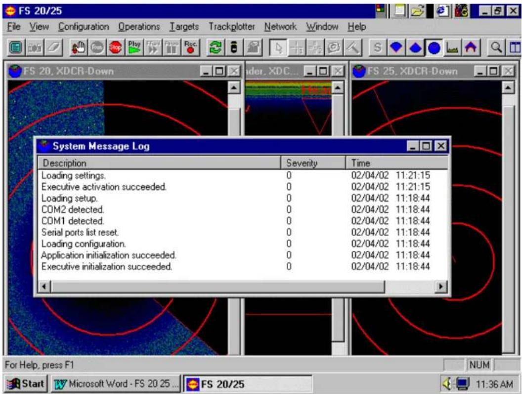
5.5 TROUBLESHOOTING
In the event the Simrad FS Trawl Monitoring system does not operate correctly, care must be taken to properly diagnose the cause of the failure. Quite often the failure is thought to be with the FS electronics when the actual cause is due to the winch slip rings, or the trawl cable. The following sections provide helpful advice on troubleshooting the FS system.
5.5.1 System Tools
The system tools available for troubleshooting the FS system are:
♦ Test Cable
Provided with every FS Trawl Monitoring system, the test cable enables the FS system to be tested without the winch slip rings or full trawl cable. This provides a quick and simple means of checking whether the problem is with the FS electronics or not.
♦ Power Supply Unit Voltage and Current Meters
The power supply unit meters allow the trawl cable voltage and current to be continuously monitored. When a fault is detected the meter values should be noted and current meter behavior observed. Jitter in the current meter may indicate current spikes due to the winch slip rings. Higher or lower values than normal (typical values: 120 Vdc, 250 - 350 mA) may indicate additional losses in the trawl cable due to physical or water damage, bad splice, etc., or problems with the trawl unit electronics.
The meters can also indicate if one of the heads is having difficulty powering up properly, by having the current fluctuate from zero to a level, back to zero and repeating this cycle continuously.
◆ Message Error Log
Refer to Section 5.1.1
♦ Monitoring Cable Gain
Refer to Section 5.4.3
The usefulness of these tools is greatly enhanced when they are used on a regular basis to monitor system performance. Records of past system performance, when units were operating properly, provide a basis for comparison that may assist in diagnosing the problem when an FS system fails.
5.5.2 Diagnosing Problems
As previously mentioned, the PC based FS Trawl Systems are more complex than prior systems to pinpoint a specific fault. The primary emphasis must be placed on determining initially if the problem can be traced to something other than the specific FS equipment itself. You must eliminate the cable, pigtail connections, slip rings and wheelhouse to slip ring cable as the source(s) of the problems.
If the FS system develops a problem (or if it fails completely), and before you start swapping out FS units, the steps below should be followed:
- Check the power supply unit meters. If the system PWR/TTM unit won't power up, ensure that all voltage switches are in the correct operating positions (i.e. ON, and at the proper power level). If the system develops a problem or fails while operating, then note the voltage and current meter behaviors. If the current meter jitters, then stop the trawl winch, if rotating, and note any changes in the meter values or their behavior.
- Monitor the System Error Message Log, as described in Section 5.4.4. The description of the errors may assist in determining the area of the system where the fault is occurring.
- Make an evaluation of whether you consider the fault to be intermittent (i.e. occurs periodically), or if the fault is "hard". "STOP" (Icon) operation of the FS system, turn the PWR/TTM unit off and power back up after a two-minute wait period. "RUN" (Icon) to restart the FS system. If the system does not run up properly, consider the fault hard and proceed to the next step.
- Disconnect the trawl unit from the trawl cable and re-connect to the FS system using the test cable. Power up the system and observe if the system powers up and operates correctly. IF the fault is still “hard”, then the problem will almost surely be in one of the FS units. If the unit runs up correctly, and does this several times correctly and runs for a period of time on the test cable, you have proven that the FS system will operate on the test cable. Some other outside influence is acting on the system to cause the hard failure. Even if you evaluated the fault as “intermittent”, running the deployment package on the test cable would be a step in the fault finding process.
Note!
If a Simrad FS unit is diagnosed as being faulty, then the unit(s) should be returned to an authorized Simrad service center. ALL system performance results and a complete description of the problem should be supplied with the defective unit to assist in its repair.
5.5.3 Common Fault Recognition Charts
This is a more complicated system than prior FS3300, MKI and MKII Processor based systems. In simple terms, the issues that existed before with the units in the deployment package (whatever configuration of heads and sensor modules) and the full 3^rd wire (including the slip rings) are the same. The relationship between the PC and the PWR/TTM unit and how the PWR/TTM unit interacts with the units in the deployment package is new, much more involved and will be the area that is the hardest to both explain and recognize if the problem is there.
As operators of the FS20 and FS20/25 systems, you should think of the system broken down into five distinct sub-sections as follows:
- PC to the "Digital" portion of the PWR/TTM Unit
- "Analog" portion of the PWR/TTM Unit to the deployment package units
- PWR/TTM Unit
- Units in the deployment package itself (Heads, Sensor Modules and Egg Receivers)
• Full 3wire assembly (Including slip rings and cable to wheelhouse)
5.5.3.1 PC to PWR/TTM Unit (Digital)
The first stage in bringing the system on line is to have the PC establish a communication link with the digital portion of the LF Sub-assemblies. As far as the PC is concerned, it is talking to, and will eventually be running “digital head(s)”. This area of the run up sequence occurs during the “Connect Heads”, and then “Detect Heads” phase (Refer to Section 4.4.4). Using an FS20/25 system as an example, the following window illustrates a communication problem between the PC and the LF2 Sub-assembly.
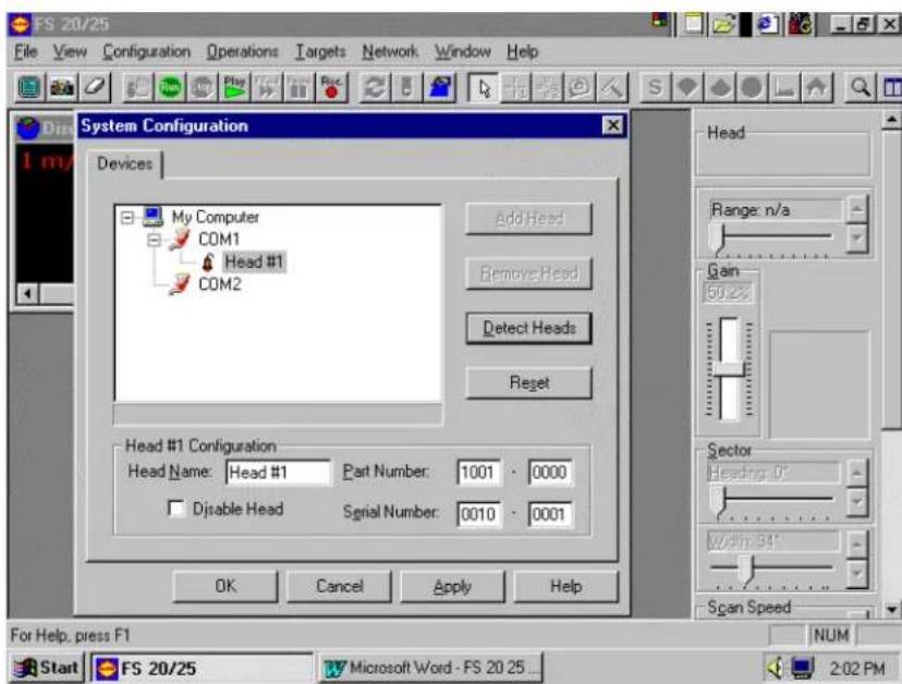
Note that Head #1 is connected to COM1, but that COM2 does not indicate any head attached. Note also that there is a Red Check beside COM2, which means that the port is enabled. This fault could indicate a problem with either the PC COM Port itself or the LF2 Sub-assembly. It does not mean that there is a problem with the FS925 head because that stage of the run up hasn't been attempted yet!
The system configuration, if installed correctly, will have the cable that plugs into PC COM Port 1 establish communication with the LF1 Sub-assembly (Vertical Head). The cable that plugs into PC COM Port 2 will establish communication with the LF2 Sub-assembly (FS925). Using the above symptoms as an example, if you did a full system run up, eventually the Vertical head would start to work but the FS925 would not.
Assume the problem is a hard fault with the PC COM Port 2; if you swap the cables on the back of computer, go through the process of connecting and then detecting the heads, you will see the same window as above. The difference will be that this time if you do a full system run up, the FS925 head will start to work and the Vertical head will not.
If the problem was with one of the LF Sub-assemblies, there will be the same type of indication as above with one of the COM Ports showing a head attached; one head would operate if you do a full system run up. If you swap the cables on the back of the computer and do a full system run up the same head will operate, only it is via the other COM Port.
The following chart lists some of the “digital” type problems, possible causes and how they can be verified.
| Problem Action/Possible Cause | |
| No Head Connection/Detection | Is COM Port enabled (red check)Ensure COM Port(s) enabled |
| No Head Connection/Detection-PC COM Port Problem | Do full system run up, one head should work, the other won'tSwap cables on back of PCFull system run up, the other head will work, the first won'tWill require service ashoreOption would be to run the head of your choice on the working COM Port, disable the other COM Port until PC is repaired |
| No Head Connection/Detection-PWR/TTM LF Sub-assembly problem | Do full system run up, one head should work, the other won'tSwap cables on back of PCFull system run up; the one head will not work on either COM PortWill require service ashoreNo option; you will only have use of the one head until the PWR/TTM repaired |
| Message Log Errors | ID 256 indicates some problem with the Vertical Section (LF1 or COM1) |
| Message Log Errors | ID 512 indicates some problem with the FS925 Section (LF2 or COM2) |
| Message Log Errors | As mentioned, there is an error code with the ID that can relayed to a repair facility by FAX or E Mail to aid in determining how the unit is failing |
5.5.3.2 PWR/TTM Unit to Deployment Package Units (Analog)
The “information” that is exchanged between the PC and the LF Sub-assemblies is in a digital format. The digital commands are translated into an “analog” format in the LF Sub-assemblies and sent down the 3^rd wire to the heads. The analog response from the heads, whether it is a command acknowledgement or sonar video and status, is relayed back up the 3^rd wire and translated back into a digital format for transmission to the PC, where it is then displayed on the monitor.
Diagnosing a problem in this area is difficult; the fault could be in the LF Sub-assembly issuing commands and receiving responses from the head or with the head itself receiving the commands and responding. In the field, you could verify a fault in the Vertical section (LF1 Sub-assembly) by running a back up vertical head. If the second head doesn't work, the problem likely is in the PWR/TTM. The problem could also be in the FS925 head (see chart below for explanation). If the backup head does work, the problem is almost certainly in the first head.
The same logic can be applied to the FS925 head, if you carry a back up FS925 on board. If not, it will almost certainly require a service representative to isolate and repair a problem in the FS925 section.
There will be specific head problems and symptoms discussed in the next section.
The following chart deals with issues referred to as “analog” type problems.
| Problem Action/Possible Cause | |
| Vertical Head will not move-Problem in vertical head | Try backup headBackup head works, problem with first head (send for repair) |
| Vertical Head will not move-Problem in FS925 | Try backup headBackup head doesn't workStop system operation, turn PWR/TTM off, connect 3^rd wire directly to vertical head (correct voltage setting on PWR/TTM)Power up, full system run up; backup OR first head works, problem is in FS925 (Pre-Regulator board)Service representative will have to repair FS925Option: Run FS925 as stand alone (disable vertical head; drawback is you lose sensor module as well)Second Option: Run vertical head (with sensor module) directly from 3^rd wire.Do this ONLY if you have dummy plugs for the FS925 2-pin connector and 38"whip connector to prevent salt water contamination |
| Vertical Head will not move-Problem in LF1 Sub-assembly | Neither Backup or first head will work through the FS925Neither Backup or first head will run as independent units on 3^rd wireCable gain high (254:255)Will require service representativeNo option; vertical head unavailable until repairs made to PWR/TTM UnitSend PWR/TTM Unit ashore for repair |
| FS925 does not operate | Difficult to isolate if no backup available as a comparator |
5.5.3.3 PWR/TTM Unit
The PWR/TTM Unit performs the following functions:
- Generation of DC Voltages to run the LF Sub-assembly electronics.
- Generation of High DC Voltage supplied to the Deployment Package (see section 5.4.1).
- Communication Interface (discussed in previous sections).
An FS20/25 System will be used as the example for an internal power supply failure to the LF Sub-assemblies. The only apparent symptom is during the Connect/Detect head process; there would be no head connected to either COM1 or COM2 (swapping cables would give the same result) and neither head would work if a full system run up was done.
A failure to the high voltage generation can be verified by measuring the voltage at the 3^rd wire pigtail (56Vdc, 120Vdc or 200Vdc)
The following chart refers to internal PWR/TTM Unit failures.
| Problem Action/Possible Cause | |
| Neither Vertical or FS925 Operates-LF Sub-assembly Voltage Failure | No indication of heads connected to either COM1 or COM2 during Connect/Detect Heads phaseBoth Vertical and FS925 heads react when PWR/TTM turned onWill require repair by service representativeNo Options: send PWR/TTM ashore for repair |
| Neither Vertical or FS925 Operates-High Voltage Generation Failure | Neither Vertical or FS925 reacts when PWR/TTM turned onHeads connected to both COM1 and COM2 during Connect/Detect Heads phaseVoltages not present at the 3^rd wire pigtailWill require repair by service representativeNo Options: send PWR/TTM ashore for repair |
5.5.3.4 Housing Units (Heads, Sensor Modules and Egg Receivers)
The previous sections dealt with problems that would be considered hard failures. The following section will discuss problems that appear more as erratic behavior and intermittent faults.
| Problem Action/Possible Cause | |
| • Vertical Head Erratic Movement-Fails Quadrant Calibration | • Remove Diaphragm Cover on Head• If diaphragm bulging out, salt water contamination in motor end• Send head ashore for repair• There will also be error message codes that indicate this problem |
| • Vertical Head Erratic Behavior-Stops, starts, error messages, but will continue working | • Indicates problem with telemetry up and down 3^rd wire OR connectors• Close inspection of 2-pin connector and female inserts of 38” whip from FS925 and Vertical 2-pin connector• Ensure that no corrosion or “burning” has taken place on connectors (part of routine maintenance)• If connectors starting to degrade, send unit(s) ashore for repair |
| • FS925 Erratic Behavior | • Same logic with respect to connector (2-pin to 3^rd wire)• Salt water contamination not an issue (dome is a sealed unit) |
| • Both Heads Erratic Behavior | • Error Messages will indicate both ID 256 and ID 512 error codes; telemetry problems with both heads• Observe cable gain numbers for both (higher than normal?)• Run full deployment package on the Test Cable• If problems not present using test cable, do a thorough check on all parts of the 3^rd wire (including slip rings) |
| • Sonar head operates but image skewed or distorted | • Check calibration for errors in sonar heads positioning (quadrant failure)• If errors, then problem with sonar head, otherwise check that sonarhead is properly mounted in trawl housing. |
| No Sensor Module Data-No depth, temperature or catch indication | Ensure sensor module connectedEnsure display of sensor data is enabledProblem can be in either the head or the sensor moduleIf backup Vertical Head and/or backup Sensor Module available, swap out units to determine which is faultySend faulty unit ashore for repair |
| Missing Sensor Module Data-Depth and temperature present-No catch indication at all (yellow bars for eggs on net, then pink when net starts to fill) | Ensure catch indication is enabledEnsure catch sensor batteries are properly chargedIf the catch indication is enabled and the batteries are properly charged then the problem will be in the sensor moduleSend faulty unit ashore for repair |
| Sensor Module Catch Indication-Depth and temperature present-Catch Indication working but fires off all the eggs at once (even channels that aren't in the water) | Caused by a power reset in the sensor module; the power to the sensor module is supplied by the headCan be caused by ship power fluctuationNormal(and acceptable) if the eggs clear and return to normal indication within 70-90 secondsNot Normalif they won't clear on their own (unit has gone into continuous reset)You should not have to turn the power off and then back on to get rid of this problemSensor Module faulty; send ashore for repairNot Normalif the frequency of this problem starts to occur more often, even if they still clear on their ownSend sensor module ashore for testing |
5.5.3.5 Full 3 ^rd Wire Assembly (Including Slip Rings and Wheelhouse Cable)
The absolutely weakest link in the entire FS Trawl Fishing System is the 3^rd Wire Pigtail Connection. If the female inserts have been contaminated with salt water and start to corrode, they will cause the 2-pin connector pins of the attached head to corrode and/or “burn”. You will start to get telemetry failures, erratic head behavior and ultimately the system will fail! It is essential that regular, routine maintenance is performed on the 3^rd wire pigtail.
The second weak link is the section of the cable that could and does experience a snap-loading effect when the trawl is deployed.
The third weak link is the slip rings. If they are dirty or corroded, you will experience telemetry errors as described in previous sections. They can also mean that we are trying to diagnose problems in the wrong area of the system (problems with heads that don't exist).
The following sections offer some tips in trying to localize problems to a specific area of the 3^rd wire assembly.
- Testing Trawl Cable
If, after testing the FS system, the trawl cable is suspected to be faulty, then it needs to be investigated to determine what and where the problem is. For problems that are not obvious, however, this can be quite difficult to do and may require someone experienced with testing trawl cables. This section provides some basic tips in troubleshooting a trawl cable, but is in no way a complete and comprehensive guide.
- Cable Impedance
The use of a Meggar to check the impedance of the trawl cable may be the most useful test. It can be done with or without the slip rings connected, and readings should be taken between the cable's two conductors and also from each conductor to the fishing vessel hull. As a minimum, the impedance should be greater than 2 Mohms, and preferably over 6 Mohms.
Caution!
The FS system MUST be disconnected from trawl cable during Meggar tests to prevent possible damage to the electronics!
If the impedance between the cable's two conductors is too low, then possible problems are bad splices, water in cable, moisture in slip rings (if connected during test), or damaged cable. If the impedance between the cable's conductors and the vessel's hull is too low, then possible causes are damaged outer jacket on cable, bad splice, or bad slip rings (if connected during test).
- Closed Loop Resistance
As previously mentioned, the closed loop resistance must be less than 100 ohms for proper operation of the FS system. This test should be done with the FS system disconnected, but with the winch slip rings included.
To do the test, the conductors at one end of cable should be jumpered together (shorted). An ohmmeter is then used at the other end of cable to measure the resistance between the conductors.
• Voltage and Current at Trawl Unit
Further checks of cable losses can be performed by measuring both the voltage and current at the trawl unit. This measurement requires the trawl unit electronics to be connected and the FS system powered up. This test is done where the trawl cable pigtail plugs into the sonar head. Jumpers will be required to breakout the signals for connection to a handheld multi-meter.
Caution!
There are DC voltages on the trawl cable that are capable of delivering a lethal electric shock!
The minimum voltage at the trawl unit is 55 Vdc and the current should be approximately 250 mA with sonar head only connected and 325 mA with both sonar head and sensor module (current readings will vary depending on operation mode - i.e., scan speed and range, etc.). This test is recommended more for a service representative than ship's personnel in the field.
• Test for Water In Cable
When a trawl cable is damaged or there is a poor splice, salt water can get into the cable. As a result, the cable may act as a battery, producing a small dc voltage across the conductors of the cable. This is detrimental to the operation of the FS system and all affected cable should be removed.
To test for this, the trawl cable should be disconnected from the FS system and a voltage meter connected to the trawl unit end of the cable. If water is present, then
there may be a reading of 2 - 3 Vdc.
5.6 SECTION 1 - CATCH SENSORS
Refer to your Simrad FA701 sensor operator and service manual or see Part 7 'Drawings' for more information.
5.7 SECTION 2 - WINCH SLIP RINGS AND TRAWL CABLE
Refer to your Manufacture operator and installation manual or see part 7 "Drawings".
PART 6
DRAWINGS
- DRAWINGS ......6.3
6.1 LIST OF DRAWINGS ....6.3
6. DRAWINGS
6.1 LIST OF DRAWINGS
The drawings below are included in the technical Information (P/N 901-10037902) which is included in this chapter.
| Drawing Number Description | |
| 359-00778000 FS 925 | TS 15S Transducer Installation Template Dwg |
| 359-00788000 FS 900 | TS 15S Transducer Installation Template Dwg |
| 436-00411000 Test Cable | |
| 436-00421000 Interconnect Cable | |
| 436-00431000 Interconnect Cable Power Supply | |
| 901-60031003 FS 20 | TTM Wiring Diagram |
| 901-60041003 FS 20/25 | TTM Wiring Diagram |
| 901-60051003 FS 20/25 | SA TTM Wiring Diagram |
| 901-60061003 FS 20 | SA TTM Wiring Diagram |
| 971-80111000 FS 900 | 1800m Deployment Housing Assembly |
| 974-80011000 FS 900/925 | 1800m Deployment Housing Assembly |
| 974-80011001 FS 925 | Stand Alone Deployment Housing Assembly |
PART 7
ATTACHMENTS
- ATTACHMENTS 7.3
7.1 LIST OF ATTACHMENTS....7.3
7. ATTACHMENTS
7.1 LIST OF ATTACHMENTS
| Drawing Number Description | |
| 820-073231 FS 3300 | Quick Release Mounting with Bridle |
| 820-073232 FS 3300 | Quick Release Mounting without Bridle |
| 824-074095 FS 3300 | Mounting with Armoured Trawl Cable |
| 519-893 Cable connection for Trawl-Eye Winch | |
| 830-056482 FA 701 Catch Eggs Sensor Installation | |
| P2152E Maintenance & Charging of Catch Eggs | |
| 854-0430793 Splicing & Jointing Trawl Cable | |
| N/A Trawl Cable Specification | |
| 901-10031802 FS 20/25 Window 2000 Operating System Set –Up | |
| 232PC12B B & B Additional 2-Serial Port Installation and Set-UP | |
| N/A Dual Monitor Display Setup Procedure | |
| N/A FS 20/25, PWR/TTM Unit Meter Charts | |
| N/A FS 20/25 PWR/TTM Unit Outline Drawing | |
- Kongsberg Simrad Mesotech Ltd Products Warranty Policy
- Underwater Equipment:
- Warranty on Parts or Equipment Replacement:
- Consumable Materials:
- Warranty Service:
- DISCLAIMER
- LIST OF CONTENTS
- MODIFICATION RECORD
- FS 20/25 OPERATORS MANUAL
- PART 1
- Equipment Configuration
- System Configuration
- Display Monitor
- Processor Unit
- Power Supply/TTM Interface Module
- Deployment Housing Unit
- Jointing Tool
- Catch Sensors
- Printer Option
- Sounder Option
- VCR Option
- Trawl Cable, Winch and Block
- PART 2
- THEORY OF OPERATION
- THEORY OF OPERATION....2.3
- Basic Principles
- Determining Target Position
- Forming an Image
- Key Feature Setting
- AGC
- RCG
- RX Gain Response and Type
- Pulse Length Control
- Optimize Resolution
- Maximize Range
- Peak Detection
- PART 3
- CONTROL PANEL
- Main Control Panel
- Tool Bar
- Header Menu Control
- Full Screen
- Save Image
- Clear Display
- Run and Stop
- Play FWD Pause Record
- Scan Reverse
- HEAD AND DISPLAY SETTING
- CURSOR
- TOOL BAR ACCESSORIES
- CATCH SENSOR
- DEPTH AND TEMPERATURE GRAPHS
- LANGUAGE
- HEADER MENU STRUCTURE
- FILE
- CONFIGURATION
- OPERATIONS
- TARGETS
- NETWORK
- WINDOW
- HELP
- INSTALLATION & SET UP
- PART 4
- FS 20/25 INSTALLATION, SYSTEM SET-UP AND TEST
- FS 20/25 INSTALLATION, SYSTEM SET-UP AND TEST ....4.3
- FS 20/25 INSTALLATION, SYSTEM SET-UP AND TEST
- INSTALLATION PROCEDURE
- SURFACE UNIT ELECTRONICS INSTALLATION
- Mounting of Units
- Power Considerations
- Connecting a Display Unit
- Connecting the Processor
- Note!
- FS 20 System Installation Procedure
- For Vertical Head, Net Sounder Option and Sensor Module:
- FS 20/25 System Installation Procedure
- For Vertical Head, Net Sounder Option, Sensor Module and Horizontal Sonar Head.
- Warning!
- Before applying the power to the processing unit, ensure that the proper AC input voltage has been selected.
- Connecting the TTM Module
- Selecting AC Supply Voltage
- Selecting the Trawl Output Voltage
- Connection to Cable Winch/Slip-Rings
- Interfacing to a Simrad Echo Sounder
- ASSEMBLING OF TRAWL UNIT
- FS 20/25 Configuration
- Note
- SYSTEM SET-UP AND TESTING USING TEST CABLE
- Start Up
- Power-Up Configuration
- FS 20Start-up Procedure
- FS 20/25 Start-up Procedure
- FS 20 or FS 20/25 RUN UP Procedure
- Display Settings
- Control Setting
- Head Sensors Setting
- FS 20 Head Setting
- Transmit Setting
- TVG Page Setting
- Info
- Auxiliary Transducer (Net Sounder)
- Auxiliary TVG Page Setting (Net Sounder)
- FS 25 Head Settings
- Save User Setting
- Final System Test
- Completing Trawl Unit Assembly
- Mounting CATCH SENSORS
- Caution!
- SAVE USER SETTING
- Note:
- PART 5
- MAINTENANCE AND TROUBLESHOOTING
- TROUBLESHOOTING AND MAINTENANCE....5.3
- TROUBLESHOOTING AND MAINTENANCE
- INTRODUCTION
- SYSTEM OVERVIEW
- FS 20/25 System
- Trawl Cable Requirements
- HANDLING & MAINTENANCE
- Wheelhouse Electronics
- Trawl Unit
- Handling Tips
- Maintenance Schedule
- Connector Maintenance
- Excessive Impacts
- Corrosion
- Shaft or Transducer Damage
- Catch Sensors
- Winch Slip-Rings and Trawl Cable
- MONITORING SYSTEM PERFORMANCE
- Test Cable
- WARNING
- If you connect an FS 3300 sonar head, with the power switch set at "FS25" (200Vdc), you will damage your sonar.
- Power Supply Meter Readings
- - Current Meter Jitters
- - Increase in Current
- Trawl Cable Gain
- ♦ Cable Gain Calculations
- System Error Messages
- TROUBLESHOOTING
- System Tools
- ♦ Test Cable
- ♦ Power Supply Unit Voltage and Current Meters
- ◆ Message Error Log
- ♦ Monitoring Cable Gain
- Diagnosing Problems
- Common Fault Recognition Charts
- PC to PWR/TTM Unit (Digital)
- PWR/TTM Unit to Deployment Package Units (Analog)
- PWR/TTM Unit
- Housing Units (Heads, Sensor Modules and Egg Receivers)
- Full 3 rd Wire Assembly (Including Slip Rings and Wheelhouse Cable)
- - Testing Trawl Cable
- - Cable Impedance
- - Closed Loop Resistance
- • Voltage and Current at Trawl Unit
- There are DC voltages on the trawl cable that are capable of delivering a lethal electric shock!
- • Test for Water In Cable
- SECTION 1 - CATCH SENSORS
- SECTION 2 - WINCH SLIP RINGS AND TRAWL CABLE
- PART 6
- DRAWINGS
- DRAWINGS
- LIST OF DRAWINGS
- PART 7
- ATTACHMENTS
- ATTACHMENTS
- LIST OF ATTACHMENTS
Brand : SIMRAD
Model : FS20
Category : Browser