
PI44 - Browser SIMRAD - Free user manual and instructions
Find the device manual for free PI44 SIMRAD in PDF.


| Product Type | Catch Monitoring System |
| Display | Color LCD with numeric and graphic presentations |
| Echo Sounder Frequencies | 38 kHz, 50 kHz, 200 kHz (dual frequency operation) |
| Maximum Sensors Supported | 6 simultaneously |
| Sensor Types | Bottom Contact, Catch, Depth, Height, Rip, Spread/Remote, Temperature (PI and PS families) |
| Power Supply | DC 12–32 V |
| Hydrophone Options | Hull-mounted (purse seine or trawl) or portable with 50 m cable |
| Data Communication | Acoustic link via coded sound waves |
| Keypad | Integrated with dedicated buttons (MENU, ENT, ADJ, PAGE, WIN, etc.) |
| Housing | Impact-resistant polycarbonate front panel, die-cast aluminum enclosure, watertight connections |
| Software Version (Manual) | 0.40 |
| Charger Compatibility | PI Charger (fast charge for PI sensors) and PS30 Charger (230 Vac, 110 Vac, or 24 Vdc) |
| Interface | NMEA 0183 input/output, serial lines |
| Menu Languages | Selectable (multiple languages supported) |
| Display Pages | 4 predefined pages with configurable window layouts (1, 2, or 4 windows) |
| Sensor Communication Channels | Configurable via PI Configurator utility |
| Update Rate Options | Fast, Normal, Slow (per sensor) |
| Alarm Types | Graphical and audible alarms for sensor status, depth, temperature, spread, etc. |
Frequently Asked Questions - PI44 SIMRAD
User questions about PI44 SIMRAD
0 question about this device. Answer the ones you know or ask your own.
Ask a new question about this device
Download the instructions for your Browser in PDF format for free! Find your manual PI44 - SIMRAD and take your electronic device back in hand. On this page are published all the documents necessary for the use of your device. PI44 by SIMRAD.
USER MANUAL PI44 SIMRAD
Catch monitoring system

www.simrad.com
Sim radPI 44
Catchmonitoringsystem
Operatormanual
Important notice
Operation of the PI44 catch monitoring system assumes that the communication between the
Operator Unit and the sensors is fully functional.
Ensure that the communication channels and update rates defined on the Operator Unit matches those of the sensors.
About this document
| RevDateWrittenbyCheckedby | Approvedby | ||
| Rev.B | 02.12.05RBrKRKR | ||
| RevisedforSWversion0.40.NewfunctionTrawlCalculatorimplemented. | |||
©2005SimradAS
ISBN82-8066-046-1
Allrightsreserved.NopartofthisworkcoveredbythecopyrightthereonmaybereproducedorotherwisecopiedwithoutpriorpermissionfromSimradAS.
The information contained in this document is subject to changing without prior notice.
Simrad AS shall not be liable for errors contained herein, or for incidental or consequential damages in connection with the furnishing, performance, or use of this document.
The equipment to which this manual applies must only be used for the purpose for which it was designed. Improper use or maintenance may cause damage to the equipment or injury to personnel. The user must be familiar with the contents of the appropriate manuals before attempting to operate or work on the equipment. Simrad AS disclaims any responsibility for damage or injury caused by improper installation, use or maintenance of the equipment.
If you require maintenance on your Simrad equipment, contact your local dealer. You can also contact Simrad using the following e-mail address: fish-support@simrad.com
Sections
1 l n t r o d u c t i o n
ThissectionintroducesthePI44catchmonitoringsystemoperatormanual. Refertopage1.
2 System description
ThissectionprovidesageneralintroductiontothePI44catchmonitoring systemandtheunitsinuse.Refertopage3.
3 Getting started
ThissectionprovidesgeneralguidelinestohelpyougetstartedwiththePI44 catchmonitoringsystem.Refertopage9.
4 Applications
ThissectiongivesanoverviewofthevariousapplicationsthatthePI44can offer.Refertopage25.
5 Display modes
Thissectiongivesanin-depthdescriptionofallthedisplaypresentations. Refertopage32.
6 Operational procedures
Thissectionprovidesdetailedprocedurestoguideyouthroughtthemost commonfunctions.Refertopage55.
7 Practical use of the sensors
Thissectiondescribeshowtoinstallanduseeachsensortype.BothPIandPS sensorsaredescribedandexplained.Refertopage103.
8 Sensor chargers
This section describes how to install and use the sensor chargers. Refer to page 164.
9 M e n u s y s t e m
This section allows you to access the reference information from the menu structure. Refertopage169.
10 References
Thissectiondetailsthevarioussetuppages,thoselectedfromthemenu systemandthoseaccessedfromthedisplaypresentation.Refertopage173.
11 PI Configurator
ThissectionexplainshowtousethePIConfiguratorutilitytochangethe sensor'scommunicationchannelandupdaterate.Refertopage226.
12 Sensor test procedures
Thissectionprovidessimpletestprocedureyoucanusetoverifythethesensors areworkingproperly.Refertopage265.
13 Technical specifications
Thissectionprovidesthebasictechnicalspecifications.Refertopage285.
14 Software updates
If you need to upgrade the software in your PI44OperatorUnit, then necessary procedures can be found here. Refertopage 291.
INTRODUCTION 1....
SYSTEM DESCRIPTION 3......
Systemdiagram4.
OperatorUnit5.
Hullmountedandportablehydrophones6.
Sensor overview 7
Batterychargers 8.
GETTING STARTED 9
How to switch power on and off 10
Introducing the presentation principles 11
Defining initial presentation pages 13
Introduction to the main menu 16
Introduction to the keypad 17
Introducing the sensors 20
APPLICATION EXAMPLES 25
Purse seine 26
Danish seine 27
Bottom trawl 28
Pelagic trawl 29
Echo sounder 30
Graphicdisplay 31....
DISPLAY PRESENTATIONS 32
Numeric display 33
Graphicdisplay 41....
Surface temperature 45
Statusdisplay 46.
Echo sounder display 50
Highway display 53
Position display 54
OPERATIONAL PROCEDURES 55
Overview 55
How to define sensor presentation 56
How to set up the sensors 58
How to mount the sensors on the net 61
How to use the sensors 62
How to replace the sacrificial water switch 63
How to test the sensors 64
How to calibrate the Depth sensor 65
Howtodefinesensoroffsets66.
HowtosetupaTwinSpreadsensorfortwintrawlapplications67....
HowtosetuptwoTwinSpreadsensorsfordualtwintrawl72.....
Howtoaccessgraphicdisplayparameters79.
Howtoviewechosounderdata80.
How to set up marker lines 81
Special features for trawl marker lines 86
How to access echo sounder parameters 88
How to use visual aids and filters 89
How to define echo sounder range 91
How to zoom in on bottom echoes 93
How to zoom in on pelagic echoes 94
How to enable A-Scope presentation 95
How to define alarm limits 96
How to select menu language 99
How to control automatic page rotation 100
How to restore default settings 101
Howtopersonalizeyoursystem 102.
PRACTICAL USE OF THE SENSORS 103
Sensor configuration 104
PI Bottom Contact sensor 107
PS Bottom Contact sensor 111
PI Catch sensor 115
PS Catch sensor 120
PI Depth sensor 124
PS Depth sensor 129
PI Height sensor 134
PI Rip sensor 138
PISpreadandRemotesensors143
PI Twin Spread 148
PI Temperature sensor 153
PS Temperature sensor 159
SENSOR CHARGERS 164
Overview 164
PI Charger 165
PS30 Charger 167
MENU SYSTEM 169
The main menu 170
Echo quick menu 172
REFERENCES 173....
Setupmap174.
Depthcalibration176.
Echopresentationsetup177....
Echosoundersetup180.
Factorypresets183
Graphic setup 184
Interface setup 187
Markerlinesetup 197....
Navigationsetup 200.
Numeric setup 202
Offset adjust 203
Pagesetup 204.
Palette setup 205
Position display setup 206
Quick guide 207
Receiver setup 208
Sensor alarms 211
Sensor setup 215
Speed setup 217
Status setup 218
Surface temperature setup 219
Temperature setup 220
Trawl calculator 221
Trawl info setup 223
Units setup 225
PI CONFIGURATOR 226
Purpose 226
Basic information 227
About sensor configuration 229
Main dialogue description 231
Operational procedures 233
References 240
Maintenance 261
SENSOR TEST PROCEDURES 265
Overview 265
Bottom Contact test procedure 266
Spread & Remote sensors test procedure 269
Catch sensor, test procedure 273
Depthsensor,testprocedure276.
Temperaturesensor,testprocedure279....
Heightsensor,testprocedure282.
TECHNICAL SPECIFICATIONS 285......
Sensors286
SOFTWARE UPDATES 291
Overview 291
DSP Software upgrade 292
MMI Software upgrade 296
PI DSP Upload 299
INDEX 300
Sensors
UsethistabletowritedownthesensorsyouuseonyourPI44catchmonitoringsystem.
| Sensor type | Serial number | Communication channel | Update rate |
Sensors
UsethistabletowritedownthesensorsyouuseonyourPI44catchmonitoringsystem.
| Sensor type | Serial number | Communication channel | Update rate |
INTRODUCTION
The SimradPI44isanintegrationofprovencommercialfishing technologies which candramatically increasetheyield and effectiveness of purse/danishseining and bottom/pelagic trawling applications.
Bymeansofsixunderwatersensorsmountedonthegear,this robust,maintenance-freecatchmonitoringsystemallows unparalleledcontroloverfishingoperationsbyproviding continuous,centralisedinformationonthevessel'sposition,its gearandtheenvironmentatandbelowthesurface.
Thismanualisnotintendedtobereadfromcovertocover,but isdesignedasabookofreferencesthatyoucanconsult whenevernecessary.
ThismanualdescribesPI44softwareversion0.40.
Topics
→ Systemdescription,page3
→ Gettingstarted,page9
→ Applications, page25
→ Displaymodes, page32
→ Operationalprocedures,page55
→ Sensors,page103
→ Menusystem,page169
→ References,page173
→ PICoufigurator,page226
→ Sensortestprocedures, page265
→ Softwareupdates,page291
Changes to this manual
The following changes have been made to this manual.
Rev.A
Thiswastheoriginalissue.
Rev.B
Operationalprocedures: Additionalproceduresadded.
Sensors: "PITwinSpread" and "Sensorconfiguration" chapters added.
Softwareupdate: This is anewsection.
Newsoftwareversion: SW0.40 implemented.Newfunction "Trawlcalculator" described.
SYSTEM DESCRIPTION
TheSimradPI44catchmonitoringsystemconsistsofan operatorstation,ahydrophoneandanoptionalechosounder transducer.Thehydrophoneandthetransducerareboth mountedunderthevessel'shall.Thesystemfurthercomprisesa numberofsmallandrobustsensorsmeasuringtheconditionson yourfishinggear.
The PI44 catch monitoringsystem can work with six sensors simultaneously.
Thesensors are powered by built-in rechargeable batteries. They are housed in titanium casings, and designed using advanced shock-absorbing materials. The information collected by the sensors are sent through the watertothe hydrophone by means of coded sound waves. From the hydrophone, the signals are sent to the operator unit, which decode the information, interprets it, and finally present it to you.
Topics
→ Systemdiagram,page4
→ Operatorunit,page5
→ Hydrophones, page6
→ Sensorsoverview, page7
→ Batterychargers,page8
System diagram

flowchart
graph TD
    A["CD11035C"] -->|A| B["Sensor Device"]
    A -->|G| C["Red Sensor"]
    A -->|F| C
    B -->|B| D["Sensor Head"]
    C -->|C| D
    D -->|D| E["Red Helmet"]
(A)=OperatorUnit
(B)=PIcharger
(C)=Hydrophone
(providescommunication
withthesensors)
(D)=Optionalecho soundertransducer. Severaltypes are available.
(E)=Sensorsmountedon thenet.Maximumsix sensorsmaybeused simultaneously, and several types are available.
(F)=Interfacesto
externalsensors(serial
lines,NMEAformat)
(G)=DCpowerinput
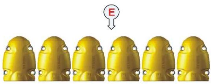
natural_image
Six identical yellow industrial components arranged in a row, with a red 'E' pointing to the top of the component (no text or symbols on the parts themselves)Operator Unit
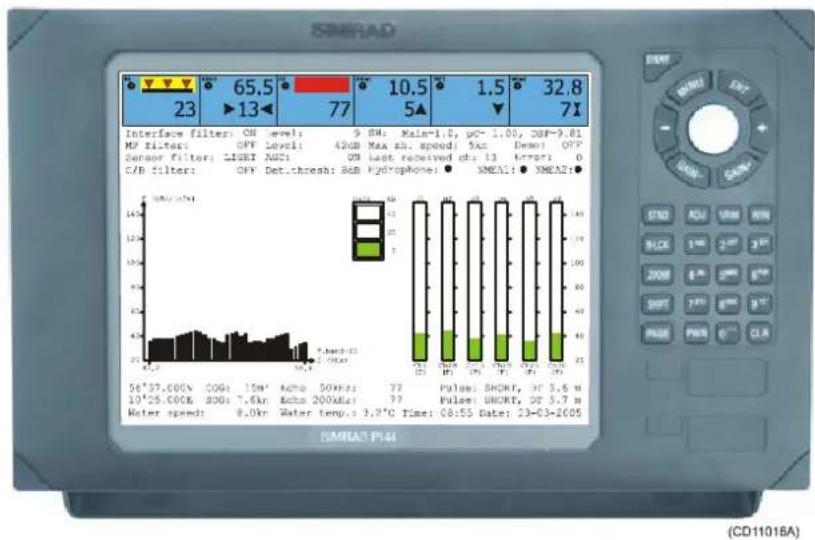
The PI44OperatorUnitisamarinegrade electronic instrument incorporating an impact resistant polycarbonate front panel, die-castaluminium housing and watertight electrical connections.
The PI44 electronics are sealed in the operator unit allowing the it to be flushor bracket mounted in the wheel house or at an exposed control station.
bar
| Parameter | Value | | :--- | :--- | | Interface filter: ON level: 9.8M; Main=1.0, pc=1.00, DBF=0.81 MP filter: OFF level: 42GB Max sh. speed: 5Aa; Demo: OFF Sensor filter: LSRF NO: 0B last received db: 13 error: 0 C/B filter: OFF Det.chresh: 8dB Hydroplone: SMEA1: SMEA2: SMA1: P144 56°37.000N COG: 15M' Kcho 50kRa 77 Pulse: 8nCKr, DT 3.6 m 10°25.000K 300A 7.6Aa Eco 200kRa 77 Pulse: UNORT, DT 5.7 m Meter speed: 8.0Km Water temp.s 3.3°C Time: 08:55 Date: 23-03-2005Computedinformationisdisplayedinbothnumericaland graphicalformonthedisplay.Theunitisoperatedusing drop-downmenusandanintegratedkeypad.
Hull mounted and portable hydrophones
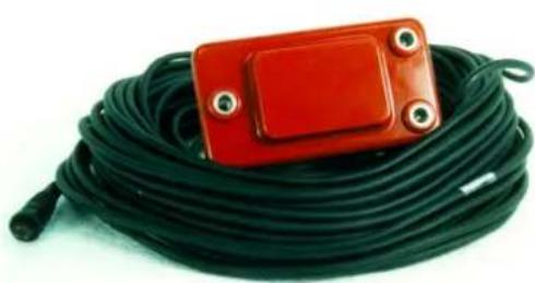
Twohullmountedhydrophonesareavailable,oneforpurse seiningoperations,andonefortrawloperations. Youcaninstall both,andthenselectactivehydrophonebymeansofaselector boxonthebulkhead.
natural_image
Coiled black cable with a red rectangular electronic component on top (no visible text or symbols)Purseseining: The hull mounted hydrophone for purseseining operations has a 90-degree horizontal beam and a 30-degree vertical beam to provide the PI44 with optimal reception from the sensors. This specific beampattern is especially suited for purseseining and the wide coverage are reduced by careful alignment.
Trawling: The hull mounted hydrophone for trawling operations has a 50 degrees horizontal beam and 30 degrees vertical beam to provide the PI44 with optimal reception from the sensors. This specific beampattern is especially suited for trawling and the wide coverage area are reduced by the need for careful alignment.

natural_image
Blue and yellow portable power cord with black cable, no visible text or symbolsPortable: Aportablehydrophoneisalso available. It is designed as atemporary measure until a fixed hydrophone can be installed at the vessel's next planned dry docking. I thas anomni-directional beam and a 50 meter integrated cable which is sheathed in polyurethane providing robust external protection to compliment its 150 kgtensile strength. The cable issupplied on areelfor convenient retrieval and stowage, and is equipped with plug foreasy attachment to the Operator Unit.
Sensor overview
Thischapterprovidesaveryshortdescriptionofeachsensor.
- Depthsensor-TheDepthsensorprovideinformationabout thecurrentdepthaswellasthedescendingorascendingrate relatedtothesurface.
- Catchsensor-TheCatchsensorprovidesinformationabout theamountofcatchinthetrawl. Thesensormonitorsthe openingofthemeshesinthecod-end, andwillactivateonce thecaughtvolumepullsthedetectorwire. Tomonitorthe fillingrate, youareadvicedtouseminimumtwosensors.
- BottomContactsensor-TheBottomContactsensors detectsifatrawlisaccidentallyliftedofftheseabed,ora purseseineistouchingthebottom.
- Ripsensor-TheRipsensorprovidesanimmediatewarning whenthenetisripped.
- Temperaturesensor-Temperature sensors read and transmit the ambient watertemperature at the geardepth.
- Heightsensor-TheHeightsensorcontainsssmallecho soundertomeasurethecurrentdepthrelatedtotheseabed.
- Spread&Remotesensor-Thesesensoralwaysworkin pairs, and they measure the distance between the trawldoors. You can also set two Remotesensors if your unatwintrawl.
Theuseofseparatecommunicationchannelsfortheindividual sensorsallowsyoutouseyoursensorsinthevincinityofother vesselsusingPIorPSsensors. Thecommunicationchannelscan bedefinedand/orchangedonboardyourvesselusingastandard computerandthePICoufiguratorutility.
Related topics
→ Moreinformationaboutthesensors,page20
→ Howtousethesensors, page103
Battery chargers
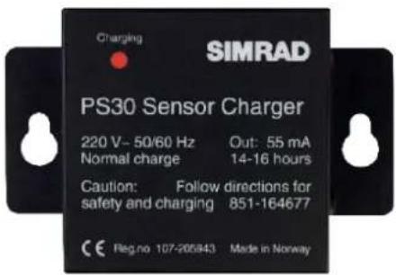
Allsensorsarepowerbyinternalbatteries,andtheseneed chargingatregularintervals.TheSimradchargershavebeen designedtoallowthesensorstobestoredinchargingpositions whenevertheyarenotused,and"overcharging"willnottake place.Eitherofthetwochargertypescanbeusedonanyofthe sensors,butthePIChargerwillonlyprovidefastchargingon thePISensors.
PS30 Charger
ThreedifferentSimradPS30Chargersare availabledependingonthevessel'smainpower supply;230Vac,110Vacand+24Vdc.
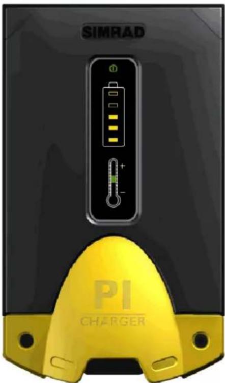
PI Charger
The PIChargerwillprovidefastchargingofthe new PI sensor series. The Simrad PI Charger requiresa+12to+32Vdcpowersupply.
Related topics
→ PICharger,page165
→ PS30Charger,page167
GETTING STARTED
Thissectioncontainsanbriefoverviewofthebasicsystem operation. If you are first time user, were recommend that you read through this chapter while operating the PI44 so that you can familiarize yourself with the buttons, menus and display presentations.
Inordertonavigatethemenustructuresanddisplay presentations,youneedtoknowthemostimportantbuttons.
MENU: Presstoaccesstheimainmenu. Pressagaintocloseit.
ENT: Presstoapplythechangesyouhaverequested.
Selectorpad(circular):Pressalongtheedgestomovethe cursor.
PAGE:Leafthroughthepredefineddisplaypages.Eachpage cancontainone,twoorfourseparatewindows.Youcanhave fourdifferentpresentationpagesactivesimultaneously,anduse thisbuttontoaccessthem.
WIN: Presstoselectactivewindowonthecurrentpresentation page. Eachpagecanhaveone, twoorfourwindows. Theactive windowisidentifiedwitharedborder.
ADJ: Presstoaccessthesetupparametersforthecurrent presentation.
Topics
→ Howtoswitchpoweronandoff, page10
→ Introducing the presentation principles, page 11
→ Defininginitialpresentationpages,page13
→ Introducingthemainmenu,page16
→ Introducingthekeypad,page17
→ Introducingthesensors, page20
How to switch power on and off
ObservethefollowingproceduretoswitchthePI44onandoff.
Poweron
1 Press and hold the PWR button until the display is switchedon.
2Observethatthestart-uppageappears.
3 Press ENT to start normal operations.
IfyoupressPAGEyouwillaccessthebuilt-in"Quickguide".
Onceopened, usethetwoGAINbuttonstoleafthroughthe pages, and then MENU or ENT to exit. If you wish to access the “Quickguide” later, you can find it on the Setupmenu.
When you power up the PI44, it will automatically assume operation using them most recent pagemode.
Poweroff
1 Press the PWR button to call up the Light and power dialogue.
2 Press and hold the PWR button to switch off the PI44.
Introducing the presentation principles
Observethe following description and procedure understand how the presentation principles apply.
PagesandWindows
ThePI44displayissetupwithfourdifferentpresentation pages. YoucanleafthroughthesepagesbypassingthePAGE buttoninthelowerleftcornerofthekeypad.
Eachpagecanbesetuptodisplayone,twoorfourwindows. Eachofthesewindowscanthenbesetuptopresentthe informationofyourchoice.
Whenyousetupapagetocontainmorethanonewindow, you canselecttheactivewindowusingtheWINbutton. Theactive windowisidentifiedwitharedborder.
Tosetupapresentationpage
Thisprocedureexplainshowtosetupapageusingthemain menuandtheWINbutton.
1 Press the MENU button to open the main menu.
2ObservetheWINsymbolinthetoprightcornerofthe display.
3PresstheWINbuttononeormoretimestoselecthow manywindowsyouwishtouseonthepresentationpage, andwhichwindowyouwishtoactive.
- The blue fields in the WIN symbol symbolises the page configuration.
-Theinformationyouchoosetodisplayduringthis sessionwillbeplacedinthecorrespondingwindowon thecurrentpage.
4Usetheselectortab, andmovethecursortotheFishery menu.
5Selectoneoftheoptionsonthemenu.
-Ifamenuoptionisshownwithredprint,itmeansthat theinformationcannotbedisplayedwiththecurrently selectedwindowsize.UsetheWINb u t t o n t o s e l e c t a newwindowsize.
- Youcanalsoselectthemenuoptionusingthe correspondingalphanumericalbutton. Youmightfind thatasiertodo!
6PresstheENTbutton.
-ThePI44willreturntothepreviouspage,andthe informationyouchoseontheFisherymenuwill appearintheselectedwindow.
If you change your page configuration from fullscreen (one window) to two four windows, you may seethat one or more windows will not display any information. If this is the case, observ the procedure below.
Todefinewindow information
Thisprocedureexplainshowtosetuptheinformationina windowusingtheWINbuttonandthemainmenu.
1If your current page contains more than one new window, press the WIN button to select active window.
-Theactivewindowisidentifiedbyitsredborder.
2 Press the MENU button to open the main menu.
3Usetheselectortab, andmovethecursortotheFishery menu.
4Selectoneoftheoptionsonthemenu.
-Ifamenuoptionisshownwithredprint,itmeansthat theinformationcannotbedisplayedwiththecurrently selectedwindowsize.Selectanotherpresentation.
- Youcanalsoselectthemenuoptionusingthe correspondingalphanumericalbutton. Youmightfind thatasiertodo!
5PresstheENTbutton.
-ThePI44willreturntothepreviouspage,andthe informationyouchoseontheFisherymenuwill appearintheselectedwindow.
Window sizes and information
Observethetablebelowtoseewhichmodesthatcanbeusedin eachwindowsize.
| WindowsizeFULLHALFQUARTER | |||
| Numericdisplay-Yes | Yes | ||
| Graphic display | Yes | Yes | Yes |
| Surface temperature | Yes | - | Yes |
| Status display | Yes | - | - |
| Echo display | Yes | Yes | Yes |
| Pilot display | Yes | - | Yes |
Defining initial presentation pages
Observethefollowingproceduretosetupthefourdisplaypages onthePI44. Thepresentationschosenarethosecommonlyused, butusingtheguidelinesinthisprocedureyoucanchangethe contentofindividualpagestosuityourrequirements.
Notethatalthough procedure instructs you outousethe Selectorpad tomakethemenuselections, you may find it much asierto accessthe choices directly using the alphanumeric buttons.
Page1:Echosounder
1 Press the MENU button to bring up the main menu.
2 Press the Selector pad to move the cursor (inverse video) totheECHOchoiceonthemainmenu.
3ObservetheWINiconatthetoprightcornerofthe display. Press the WIN button repeatedly until the blue rectanglecoverstheentireicon.
4 On the Echo menu, select Echo 38 kHz.
5 Press the ENT button to enter the choice.
Afullscreenechosounderappears. If you already know the basic setting of an echosoundery you can access the Echo quick menu by pressing the ENT button one more time.
Page2:Numericdisplay
1 Press the PAGE button once to select the next display page.
2 Press the MENU button to bring up the main menu.
3 Press the Selector pad to move the cursor (inverse video) totheFisherychoiceonthemainmenu.
4ObservetheWINiconatthetoprightcornerofthe display. Press the WIN button repeatedly until the blue rectanglecoversthelefthalfoftheicon.
5 On the Fishery menu, select Numeric display.
6 Press the ENT button to enter the choice.
Thenumericdisplayappearsontheleft(orrright)halfofthe displaypage.Ifyoualreadyknowhowtoperformthebasic setup, you can access the Numeric setup by pressing the ADJ button.
Therightsidemayhavebeenpredefinedtoprovideanother displaypresentation,oritmaysimplyshowthetextSelect displayviaMENU.Inordertofillthespace,proceedasfollows:
7PresstheWINbutton,andobservetheredbordermoving fromonewindowtothenext.Piacetheborderonthe windowyouwishtodefine.
8 Press the MENU button to access the main menu.
9 Press the Selector pad to move the cursor (inverse video) totheEchomenu.
10 On the Echo menu, select Echo 200 kHz.
11 Press the ENT button to acknowledge.
The200kHzechosounderwillnowappearinthechosen window.
Page3:Graphicdisplay
1 Press the PAGE button once to select the next display page.
2 Press the MENU button to bring up the main menu.
3 Press the Selector pad to move the cursor (inverse video) totheFISHERYchoiceonthemainmenu.
4ObservetheWINiconatthetoprightcornerofthe display.PresstheWINbuttonrepeatidlyuntiltheblue rectanglecoverstheentireicon.
5 On the Fishery menu, select Graphic display, Echo 38 kHz.
6 Press the ENT button to enter the choice.
Thegraphicdisplayappearswiththesensordashashownonthe topandtheechosoundershownbelow.Ifyoualreadyknow howtosetupthebasicparametersyoucanaccesstheEcho quick menu by pressing the ENT button one more time.
Page4:Navigationdisplay
1 Press the PAGE button once to select the next display page.
2 Press the MENU button to bring up the main menu.
3 Press the Selector pad to move the cursor (inverse video) tothePILOTchoiceonthemainmenu.
4ObservetheWINiconatthetoprightcornerofthe display.PresstheWINbuttonrepeatidlyuntiltheblue rectanglecoverstheentireicon.
5 On the Pilot menu, select Highway.
6 Press the ENT button to enter the choice.
Thenavigationdisplayappears. If you already know how to set up the basic parameters you can access the Navigation setup page by pressing the ADJ button.
Leafingthroughthepages
Toleafthroughedisplaypresentationsyouhavedefined, pressthePAGEbutton.
Otherdisplaypresentations
Severalotherdisplaypresentationsareavailable, butyouonly havefourdifferentdisplaypagestouse. Aftersomeexperience withthePI44system, youwillhoweversoonfindoutwhich displaypresentationsthatarethemostusefultoyou, andyou canalterthesetupaccordingly.
Related topics
→ Displaypresentations,page32
Introduction to the main menu
Themainmenuislocatedacrossthetopofthedisplay.Toopen themenu,presstheMENUbutton.Notethatifitisleft unactivated,themenuwilldisappearautomaticallyafterafew seconds.
| ECHO SOUNDER | WIN | |||
| 1FISHERY | 2ECHO | 3PILOT | 4SETUP | |
(CD11034B)
Eachofthefouroptionsofthemainmenuprovideadrop-down menu.Onthese,youcanselectwhichinformationtoviewin eachdisplaywindow,orwhichparameterstodefine.Mainand drop-downmenusarehighlightedwhenselected,andthe completemainmenutitleisdisplayedinthetopleft-handcorner ofthescreen.
Observe the WIN icon in the top right corner. Using the WIN button, you can position the information into these selected window on the current page. Note however that setup pages are not affected by the choices you make with the WIN button.
- To open a sub-menu, press the ENT button, press the correspondingalphanumericalbutton, orpress "down" onthe selectortab.
- Tomakeyourselection, highlightthechoiceandpressthe ENTbutton. Youcanalsopressthecorresponding alphanumericalbutton.
Related topics
→ Thechoicesonthemainmenu,page170
Introduction to the keypad
ThekeypadisusedfordirectuserinterfacewiththePI44 system, and allowsyoutocontrolthefunctionality. Notethatthe majorityofthebuttonsaremainlyusedonlyduringecho sounderoperations, and thatsomeofthemwillonlyworkwhen theyareenabledbyaspecificfunction.

EVENT: This button places a vertical marker on the echosounder depth display to identify an event.
MENU: Thisbuttonturnsthemenubaronandoff. It will also allow you to exit dialogues without applying any changes.
ENT(Enter): Thisbuttonallowsyoutoapplythe changesyouhavemadeinasetupdialogue,ortoselect afunctionfromthemenu.Thisbuttonwillalsogive youaccesstothe“Echoquickmenu”,anditwillopen thesetupdialogueforthepresentationintheactive window.
Selectorpad:Usethisbuttontonavigatethrough menusanddialogues.Itmovesthecursorhorizontally bypassingitontheleftorrightside,andverticallyby pressingitonitstoporbottom.
-/+:Thesetwobuttonareusedtoselectbetween availablevalues,scalesandranges.(-)reducesand(+)increasesthegraduation.
GAIN: Thetwogainbuttonsareusedtoadjustthe receivergainontheechosounder.
STND(Standard):Thisbuttonwillactivateanechosounder windowinStandardmode.Ifyoupressthisbuttonwhilean otherwindowisactive,thedisplayswitchestoanechosounder page.Ifoneofyourotherpagesalreadycontainsafullscreen echosounder,thePI44willautomaticallychangetothispage, andyoumustpressthePAGEbuttontoreturntoyourprevious page.Ifyoudonothaveanechosounderpresentationamong yourfourpresentationpages,thecurrentpresentationwillbe replacedbytheechosounderpresentation.
ADJ(Adjust):Thisbuttonprovidesadirectaccesstothesetup parametersforthedataintheactivewindow.Toexitthesetup withoutmakingchanges,presstheMENUbutton.
VRM(VariableRangeMarker):Thisbuttonprovides a horizontalmarkerlineontheechosounderdisplay. Use the selectorpadtoalterthedepthofthemarker. Thebuttonwill onlyworkifyouhaveanechosounderpresentationonthe currentpage.
WIN(Windows): This button is used to select which display window to be active. During normal operation, the active window is identified with a red border. When them main menu is opened, the current active window is shown in the upper right corner of the display.
B-LCK(Bottomlockexpansion):Thisbuttonwillactivatean echosounderwindow,andthenexpandtheareajustabovethe bottom.Intheexpandedview,thebottomwillappearflat.The verticalrangeoftheexpansionwindowisdefinedintheecho soundersetup.Ifyoupressthisbuttonwhileanotherwindowis active,thedisplayswitchestoanechosounderpage.Ifoneof yourotherpagesalreadycontainsafullscreenechosounder,the PI44willautomaticallychangetothispage,andyoumustpress thePAGEbuttontoreturntoyourpreviouspage.Ifyoudonot haveanechosounderpresentationamongyourfourpresentation pages,thecurrentpresentationwillbereplacedbytheecho sounderpresentation.Toswitchoffthisfunction,pressthe STNDorSHIFTbuttons.
ZOOM: Thisbuttonwillactivateanechosounderwindow, and thenexpandanareaaboveandbelowahorizontalmarkerline. Thedepthofthemarkerlinecanbeadjustedwiththeselector pad,whiletheverticalrangeoftheexpansionwindowisdefined intheechosoundersetup.Ifyoupressthisbuttonwhileanother windowisactive,thedisplayswitchestoanechosounderpage. Ifoneofyourotherpagesalreadycontainsafullscreenecho sounder,thePI44willautomaticallychangetothispage,and youmustpressthePAGEbuttontoreturntoyourprevious page.Ifyoudonothaveanechosounderpresentationamong yourfourpresentationpages,thecurrentpresentationwillbe replacedbytheechosounderpresentation.Toswitchoffhtis function, press the STND or SHIFT button.
SHIFT: This button will activate the Phased range echo sounder mode. You can then select start range with the + and - buttons, and depth range with the numerical buttons (1 to 9). If youpressthisbuttonwhileanotherwindowisactive,the displayswitchestoanechosounderpage.Ifoneofyourother pagesalreadycontainsafullscreenechosounder,thePI44will automaticallychangetothispage,andyoumustpressthe PAGEbuttontoreturntoyourpreviouspage.Ifyoudonot haveanechosounderpresentationamongyourfourpresentation pages,thecurrentpresentationwillbereplacedbytheecho sounderpresentation.ToselectStandardmode,pressthe STNDbutton.
PAGE:Thepagebuttonisusedtoleafthroughthepredefined presentationpages.Ifyoupressandholdthisbuttonformore thanthreesecseconds,youwillstartautomaticpagerotation.The PI44willthenleafthroughthefourpagesautomatically.The pagerotationinterval(timeusedtodisplayeachpage)is controlledbypagesetupparameter.Toswitchthisfunctionoff, pressanyotherbutton.
PWR(Power):Thisbuttonisusedtoswitchthesystemonand off.Duringoperation,itisalsousedtoadjustthedisplay brightnessandcontrast.
CLR(Clear):Thisbuttonwillremovethevariablerange marker.Itwillalsocleartheinputfieldsindialogues.
0 to 9 : Thealphanumericalbuttonswillgreatlyspeedupyour menuoperations,asyoucanaccessmostmenuitemsusinga number. Youcanalsousethesebuttonstoinsertdatainto dialoguefields.Duringechosounderoperations,theywilleven provideyouwithfastaccesstoasetofpredefineddepthranges. The0buttonwillenableautomaticdepthrangeselection.
Introducing the sensors
The PI44 catch monitoring can be used with a variety of sensors. All these sensors can be placed on your trawl or purse seinetomonitor key parameters.
OnthePI44,youcanusemaximumsixsensorssimultanously.
There are two sensor families; PI and PS. The sensors in the twofamiliesarealmostidentical, and they can be used together on the same PI44 system. The PIsensors will however offer increased range, some added functionality, and they can also be charged much faster using the PICharger.
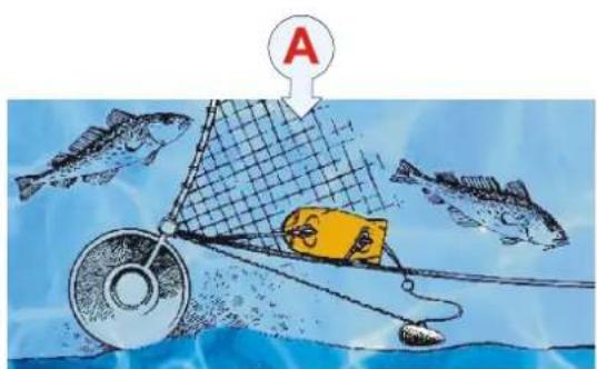
Bottom Contact: Bestatthebottom!
Withpatentedtechnologyandawardwinningdesign,Simrad providesyoufullcontroloftheactionsthattakeplaceatthe bottom.Mountedonabottomtrawl,pelagictrawlorpurse seine,thisssensorwillprovidetheimportantinformationwhen youneedit!
natural_image
Illustration of a fishing net with a yellow fish and a net, surrounded by fish in the ocean (no text or symbols)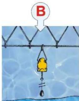

natural_image
Illustration of a yellow cartoon character fishing from a net in water, with a red letter 'C' above (no text or symbols on the diagram itself)(CD11202C)
(A)=TheBottomContactsensormountedonabottomtrawl willletyouknowoncethetrawlliftsafewcentimetersabovethe bottom. Youcanthenimmediatleyperformthenecessary adjustments, and you will not lose anycatch.
(B)=Onapurseseineyouwillbenotifiedoncetheseine reachesthebottom, andyoucanthusfishevenonarough bottom.
(C)=Onapelagictrawl,thesensorwillnotifyyouonceyouget nearthebottom.
TheBottomContactsensorwillletyouknowimmediatelyif yourgeartouchesthebottom.
- Bottowtrawl: If your trawlliftsoffthebottom, this may cause fishtoescape, and hencereducethecatch. This sensor will detect this, and allow you to trim you equipment for perfect balance.
- Pelagic trawl: On a pelagic trawl, this sensor proves very usefulwhentetrawlmovesdownwards.Itwillletyou knowimmediatelyifthefootropetouchesbottom.
- Purseseine: When you work with apurseseine, you need to know when these in each the bottom. This sensor will let you know once it happens.
- Danish seine: Used on a Danish seine, the sensor will let you knowwhenthenethasastablebottomcontact,andwhenit istimetohaul.
- Scientificresearch: During scientific surveys, an exact definition of towed distance with proper ground gear contact is an essential parameter in bottom trawlswept area estimates off fish abundance. Using a Bottom Contacts sensor will reduce errors in this key parameter.
Catchsensor:Whenisthetrawlfull?
Thisisyour “eye” atthecod-end. With PICatchsensorsinuse, youcaneasilymonitor the filling rate and the amount of catch in the trawl. Savetime and fuel, haulinthetrawl at theright moment! Thedesign is rugged and award winning, and the sensor’s sensitivity is easily adjustable for trawl so fallsizes.
SomeprofessionalsclaimthattheCatchsensoristhemost importantsensoronthetrawl.Why?Becauseitwilltellyouthe amountofcatchinthetrawl.
Thesensorsimplymonitortheexpansionofthemeshesinthe cod-end.Oncethevolumecaughtisenoughtoexpandthe meshes,theywillpullthedetectorwiresandengagethesensor. Thesensitivityofthesensorcaneasilybeadjusted,justextend thedetectionrubberbandstospanadditionalmeshes.
Tomonitorthefillingrate, were recommend that you use minimumtwosensors. Placethefirstsensoratthefarendofthe cod-end, it will tell you that the trawlis actually fishing. Place thesecond sensor closerto the trawlopening. Oncethetrawlis filled to the chosen location, the sensor is engaged, and you know that it istimetohaul.
Use the PICatchsensortoadjustthecatchvolumeaccording to theproductioncapacity, check that the trawl is fishing, adjust the caught volumetosecure quality, and minimizethetowing timetosave fuel. These are only a few of thereasons why this sensor is considered to be so important.
Depth: How deepcanyougo?
Whenthesonarandechosoundertellyouhowdeeptheschool goes,itisgoodtoknowthatyoucanplaceyourfishinggearat thesamedepth.Andevenbetter,youcanmonitorandholdthe desireddepth.Thedesignisruggedandawardwinning,andthe sensorisavailableforthreedifferentdepthranges.
ThePIDepthsensorprovidesinformationaboutthecurrent depthandthedepthchangesofyourgear.
- Bottomtrawl: Onabottomtrawl, you will usethesensorto achieve full control when shooting, and toposition the trawl on the slope.
- Pelagic trawl: During pelagic trawling, you know how importantitistopositionthetrawlrelativetothe largest concentrationoffish. By usingaDepthsensor, you can monitor the exact depth relative to the surface, and adjust the trawl depth accordingly. Additional depth sensor on the doors will monitor if the doors stay at the same depth.
- Purse seine: During seining, use the Depth sensor to monitor the depth of thenet, and the descendings speed of thenet. Then you will know when start pursuing, and which speed touse.
- Danishseine:MountedonaDanishSeinetheDepthsensor monitorsthesinkingspeedofthenet, anditwilltellyou whentostarthaulingoncethenethasstoppedsinking.
Heightsensor: Accurated distancetothe bottom!
Withabuilt-inechosounder, this new PIsensorisfullof advancedtechnology. Whereveryouplaceit, it will alwaystell youtheexactdistancetothebottom.
Theheightsensormeasurestheheightoverthebottom,thatis thedistancefromthebottomanduptowhereverthesensoris located.Thisprovidesyouwithavaluablerangeofapplications forbottomandpelagictrawling.
- Bottomtrawl: Placethesensorbehindtheheadrope, and it will tell you the height of the trawlopen. This allows you to adjust you equipment immediately if the opening is reduced, and you will avoid loosing catch.
- Pelagictrawl:Withaheightsensorbehindthefootropeyou willknowatonceifthetrawlapproachesthebottom.If you useasecondsensorbehindtheheadrope,thedifference betweenthetwomeasurementswillgiveyoutheheightof thetrawlopening.
Rip:Checkfordamages!
TheRipsensorisidenticaltotheCatchsensor,andcanthusbe regardedasaapplicationfortheCatchsensor.Placethesensor onthetrawlbellybehindthefootrope,anduseittodetectifthe trawlistornorinanyotherwaysdamagedbyrocksorother roughnessonthebottom.Ifthisisdetectedimmediatelyyoucan adjustthegeartominimisethedamage.
SpreadandRemote:CheckthetrawIdoors!
Thisdynamicduotellsyoutheexactdistancebetweenthetrawl doors.UsedonbottomandpelagictrawlstheSpreadand Remotesensorsprovidecrucialinformationaboutyourtrawl behaviour.Onatwintrawl,simplyaddaRemotesensorand youhavebothopeningscovered!
Thesetwosensorsalwaysworkinpairs. Theyareused to monitor the physical distance between the trawldoors during bottom and pelagic trawling.
UseaSpreadsensorontheportdoorandaRemotesensoron thestarboarddoor.Bothsensorsarenormallymounted in specialadapters, butyoumayalsoattachedthemtothe wing-endorwarpusingsnaphooksorrope.
TheSpreadsensorcommunicateswiththeRemotesensorusing aspecialtransversecommunicationlink.Bymeansofthislinkit measuretheexactdistance(maximum350meters)between thetwosensors.Theinformationisistransmittedtothevessel bytheSpreadsensor.
Asyoualreadyknow, correctdoorspread is important in order to obtain the correctsweep-angle, asthisensures optimal trawl performance. Door behavior and stability during shooting and towing is also monitored by these sensors. Many regard this pair of sensors one of them most important sensor stooftainefficient trawling.
A special version of the PI Spread sensor, The PI Twin Spread, allowsyoutouseasinglSpreadsensorwithtwoRemote sensorstomonitoratwintrawl.
Temperature: Toowarmortoocoldwater?
Fishing into warmortoocold water may be just a waste of time and money. Thesame appliestoapelagictrawl placed on the wrong side of a thermall layer. Using advanced technology, rugged construction and award winning design, the PI Temperature sensor allows you to increase your fishing efficiency.
The PITemperaturesensor tells you the exact seawater temperature while you are fishing.
Thewatertemperatureisanimportantparameter.Fishandbait aretemperaturesensitive,andtheyarenormallyfoundwithin specifictemperaturezonesforfeedingandspawning.
However, the temperature layers in the water are changing constantly, and for this reason the temperature must be monitored constantly. Fishing in an area with unfavourable water temperature might be just awaste of time!
Foranykindoftrawling, usethissensortomonitoring and log the temperature. Then, increase your knowledge about the correlation between temperature, fish concentration and catch efficiency. On apursesinenet, monitor the temperature to see when you are passing the thermo-cline.
Related topics
→ Purseseine, application, page26
→ Danishseine, application, page27
→ Bottomtrawl, application, page28
→ Pelagictrawl, application, page29
→ Sensorconfiguration,page104
→ PIBottomContact,page107
→ PSBottomContact,page111
→ PICatch,page115
→ PSCatch,page120
→ PIDepth,page124
→ PSDepth,page129
→ PIHeight,page134
→ PIRip,page138
→ PISpread&Remote,page143
→ PITwinSpread,page148
→ PITemperature,page153
→ PSTemperature,page159
APPLICATION EXAMPLES
TheSimradPI44systemisdesignedtofulfillallyour requirementswithinarangeofspecificapplications.This chapterprovidesafewexamplesonhowthevarioussensorscan beplacedonyourfishinggear.Italsoprovidesabrief descriptionoftheechosounderandgraphicdisplay functionality.
Topics
→ Purseseine, application, page26
→ Danishseine, application, page27
→ Bottomtrawl, application, page28
→ Pelagictrawl, application, page29
→ Echosounder, application, page30
→ Graphicdisplay, application, page31
Purse seine
When used for purseseining, the PI44 system must have one or more of the following sensors attached to the net: Depth sensor, Bottom Contact sensor and Temperature sensor.
Thesystemisdesignedtobeusedwithuptosixsensors, optimallytwoDepthsensors,oneTemperatureandoneBottom Contactsensor.Thesensorconfigurationcanbetailoredtosuite individualneeds.
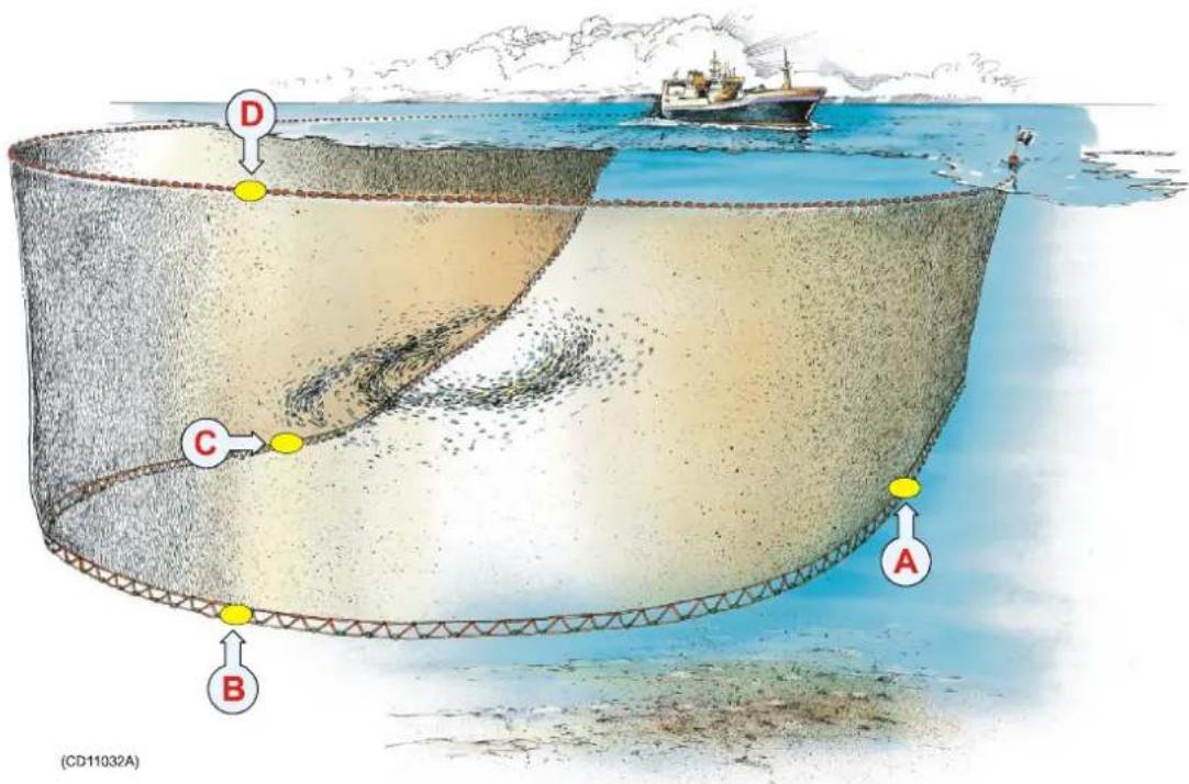
(A) = (B) = Depth/BottomContactsensor
(C)=Temperature/BottomContactsensor
(D)=Depthsensor(placedontheheadropetowarnifitsinks)
Using there recommended sensors, the PI44 system will provide the following information:
- Whentobeginpursing, and whichspeedtouseforthemost efficientpursing
• Locationofthenetrelatedtotheschool
• Bottomapproximationwithoutnetcontact - Netsinkrate,whenthenethasstoppedsinking,andwhenit startstorise
• Watertemperatureatdifferentdepths
• Whenthegearpassesthethermocline
Danish seine
When used for Danish seining the PI44 system needs upto three of the following sensors attached to the net: Depth and Bottom Contact.
Thesystemisdesignedtobeusedwithuptosixsensors. You canusetwoDepthsensors(locatedatthetopandbottomofthe net),aHeightsensor(onthetopofthenet)andoneBottom Contactsensor. YoucanalsouseaSpread/Remotecombination onthewingends.Sensorconfigurationcanbetailoredtosuite individualneeds.

(A)=Bottomcontactsensor
(B) = (C) = Depthsensors
Using therecommended sensors, the PI44 system will provide the following information:
- Whentostarthauling
• Monitornetsinkagerate
• Bottomapproximationwithoutnetcontact
• Netopening(usingtwodepthsensors)
Bottom trawl
When used for bottom trawling, the PI44 system will give you all necessary information about the trawl status. You should haveminimum three of the followings sensors attached to the net: Depth sensors(s), Bottom Contact sensor, Rip sensor and Catch sensors(s).
Thesystemisdesignedtobeusedwithuptosixsensors. We recommendthatyouuseaBottomContactsensorbehindthefootrope,aHeightsensorbehindtheheadrope,twoCatch sensors,aTemperaturesensorandaSpreadsensor.Sensor configurationcanbetailoredtosuiteindividualneeds.

(A)=Depthsensor(headrope)
(B)=Depthsensor(footrope)
(C)=Bottomcontactsensor
(D)=Ripsensor
(E)=(F)=Catchsensor(s)
Using therecommended sensors, the PI44 system will provide the following information:
- Optimalvesselspeedwithregardtonetsinkrateandbottom approximation.
• Whenthecodendisfull.
• Footwire/bottomlift-off.
• Netopening(usingtwodepthsensors)anddamage
Pelagic trawl
When used for pelagic trawling the PI44 system must have one or more of the following sensors attached to thenet: Depth sensor(s), Bottom Contact sensor, Temperature sensor, Rip sensor and Catch sensor(s).
Thesystemisdesignedtobeusedwithuptosixsensors. We recommendthatyouuseaBottomContactsensorbehindthefootrope,aDepthsensorbehindtheheadrope,twoCatch sensors,aTemperaturesensorandaSpreadsensor.Sensor configurationcanbetailoredtosuiteindividualneeds.

(A)=Depthsensor(headrope)
(B)=Depthsensor(footrope)
(C)=Bottomcontactsensor
(D)=Ripsensor
(E)=Temperaturesensor
(F) = (G) = Catchsensors
Using there recommended sensors, the PI44 system will provide the following information:
- Optimalvesselspeedwithregardtonetsinkrateandschool location.
- Whenthecodendisfull.
• Bottomapproximationtoavoidnetcontact.
• Netopening(usingtwodepthsensors)anddamage
• Ambientwatertemperatureatgeardepth.
Echo sounder
The built-inechosounderwill provide information about depth, bottomcontours and the presence of fish below the vessel. The echosoundercanusethree frequencies; 38kHz, 50kHz and 200kHz. Twofrequencies can be operated simultaneously.
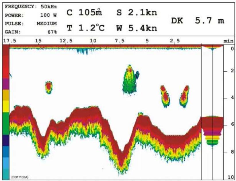
heatmap
| Time (min) | Value | |------------|-------| | 0 | 0 | | 2.5 | 6 | | 5 | 8 | | 7.5 | 4 | | 10 | 6 | | 12.5 | 8 | | 15 | 10 | | 17.5 | 12 |The following operational modes are available
- Standardmode: Rangestartisfixed, and the depth range can be altered
- Phasedrangemode: Therangestartcanbeadjusted, and the currentvalueisaddedtothedepthrange
- Bottomlock: Theechosounderprovidesanexpansion windowtostudytheechoesclosesttothebottom.
- Zoom: Theechosounderprovidesanexpansionwindowto studyechoesinthewatercolumn.
• A-scope: Singlepingechopresentation
Graphic display
Bymeansofthebuilt-inechosounderandtheinformation providedbytheanaloguesensors,youcansetupagraphic displaytogiveyouatotaloverviewoftheunderwatersituation.

line
| Time (min) | Value | |------------|-------| | 23 | 65.5 | | 13 | 77 | | 49.5 | 1 | | 1.5 | 32.8 |(CD11102N)
Thegraphicdisplaypresentstheechogramatthebottomofthe screenwhilethenumericalsensorpresentationsarelistedatthe topofthescreen.Theinformationfromthose sensors providing analoguedata(Depth,Height,TemperatureandSpread)are superimposedontheechogram.
Related topics
→ Howtosuperimposeechosounderdata,page80
→ Howtosuperimposemarkerlines,page81
DISPLAY PRESENTATIONS
ThePI44supportsarangeofdisplaypresentations. These are theinformationelementsthatyoucanchoosetoseeoneach page.
Topics
→ Numericdisplay,page33
→ Graphicdisplay, page41
→ Surfacetemperature,page45
→ Statusdisplay, page46
→ Echosounderdisplay,page50
→ Highwaydisplay,page53
→ Positiondisplay,page54
Numeric display
Thenumericdisplayprovidesvitalsensordatainlarge,easyto readdigitsandsymbols.Inthefollowing,allsensor presentationsareexplainedindetail.
Notethatdependingonthewindowsize,thesensordatamaybe shownwithdifferentlayouts,andevenwithsomeofthe informationremovedduetothelimitedspaceavailable.

heatmap
| Metric | Value | |--------|-----------| | D1 [m] | 25.6 | | T2 [°C] | 1.3 | | C3 [m] | 123 | | B4 [m] | 8 | | S5 [m] | 69.5 | | H6 [m] | 3.1 |Thisillustrationshowsatypicaltwindisplaysetupwiththenumericpresentationfrom sixsensorsontheleftsideandanechosounderpresentationontherighthandside.
The background colour for the numerical display presentations can be selected individually from the palette. If the data from the sensors are unstable, the presentations will set the following character presentations:
???-Thesensorprovidesuncertainreadings.
±±±-NocommunicationbetweenSpreadandRemotesensors
***.*-Nocommunicationwiththesensor.
Topics
→ BottomContactsensorpresentation, page35
→ Catchsensorpresentation,page36
→ Depthsensorpresentation, page37
→ Heightsensorpresentation, page38
→ Spreadsensorpresentation,page39
→ Temperature sensorpresentation, page40
Tochangepresentationparameters
Thenumericpresentationsarecontrolledbytheparameters definedinthesetup.Tochangetheseparameters,makethe presentation window active, and press the ADJ (Adjust) or ENT buttontoaccesstheNumericsetuppage.
Related topics
→ Numericsetup, page202
Bottom Contactpresentation
TheBottomContactsensorpresentationisshownbelow.

flowchart
graph TD
    A["A"] --> B["B4"]
    B --> C["C"]
    D["D"] --> E["E"]
    E --> F["()"]
    style D fill:#ffcccc,stroke:#333
    style E fill:#ffcc99,stroke:#333
    style F fill:#ffffff,stroke:#333
(A)Thecharacterandthenumberidentifiesthetypeofsensor, andwhichidentificationnumberthesensorhasonthePI44 system. In this example, B4 meansthatitisabottomcontact sensor, and that itissensorno. 4.
(B)Statusfield.Thethreearrowsdisplay“bottomcontact”, graphicallyrepresentedbytheblackorreddownwardpointing arrowsincontactwiththehorizontalblackline.Uponlossof bottomcontact,thearrowswillrisefromtheblackline(seabed) andchangecolourfromblacktored.Atthesametimean audiblewarningissounded,andthetimerstarts.Bottomsensor measurementrangemaybeadjustedasnecessary.
(C)Timer,recordshowmanyminutesthathaveelapsedsince thesensorlostbottomcontact.Ifthebottomcontactisregained, thetimerstops.Itisthenrestartedoncethestatuschangesagain. ThetimermustbemanuallyrestartedintheNumericsetup.
(D) Yellowpulselampblinkseachtimeasignalisreceived from the correspondingsensor.
(E)Interferencewarning,activatedwhenthePI44detects interferencefromothernearbyvessel(s)operatingonthesame channelorwithsimilarhydroacousticequipment.Contactyour Simraddealertoselectadifferentfrequencyshouldthis problempersist.
Catchpresentation
TheCatchsensorpresentationisshownbelow.
Note: If you use more than one catch sensor in the trawl, makes sure that you configure them with different channel numbers, and that you mount and read them in the correct order!
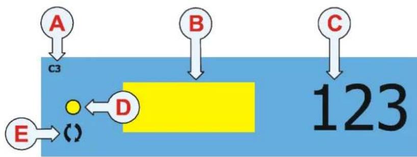
flowchart
graph TD
    A["A"] --> C3["C3"]
    B["B"] --> D["D"]
    C["C"] --> D
    E["E"] --> ()[()]
    D --> 123["123"]
(A)Thecharacterandthenumberidentifiesthetypeofsensor, andwhichidentificationnumberthesensorhasonthePI44 system.Inthisexample,C3meansthatitisacatchsensor,and thatitissensorno.3.
(B)Statusfield.Ayellowrectanglemeansthatthesensorhas notbeenactivatedyet.Aredrectanglemeansthatthetrawlhas beenfilledwithfish,andthishastriggeredthesensor.Whenthe indicatorswitchesfromyellowtoredanaudiblealarmis sounded,andthetimerstarts.
(C)Timer,recordshowmanyminutesthathaveelapsed since the sensorwastriggered. If the status switches from red back to yellow, the timer stops. It is then restarted on the status changes again. The timer must be manually restarted in the Numeric setup.
(D) Yellowpulselampblinkseachtimeasignalisreceived from the correspondingsensor.
(E)Interferencewarning,activatedwhenthePI44detects interferencefromothernearbyvessel(s)operatingonthesame channelorwithsimilarhydroacousticequipment.Contactyour Simraddealertoselectadifferentfrequencyshouldthis problempersist.
Depthpresentation
TheDepthsensorpresentationisshownbelow.
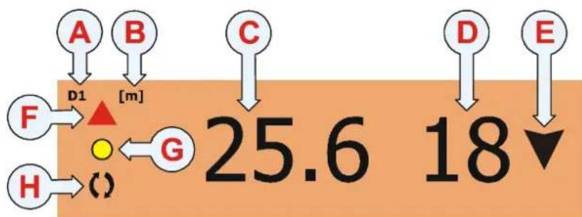
flowchart
graph TD
    A["A"] --> D1["D1"]
    B["B"] --> D1
    C["C"] --> D1
    D1 --> G["G"]
    F["F"] --> G
    H["H"] --> G
    G --> 25.6["25.6"]
    D --> 18["18"]
    E["E"] --> 18
(A)Thecharacterandthenumberidentifiesthetypeofsensor, andwhichidentificationnumberthesensorhasonthePI44 system.Inthisexample,D1meansthatitisadepthsensor,and thatitissensorno.1.
(B)Unitofmeasure.[m]meansmeter,[ft]meansfeet,[fm]meansfathomsand|pb|meansbraccia.
(C)Depthreadout.
(D)Ascendingordescendingspeedofthenetshowninunitsper minute. Thedirectionisshownwiththearrow(E). Ifthespeed is0, thearrowisremoved.
(E)Directionindicatorfornetmovements.
(F)Graphicalarm. Thedirectionofthetriangleindicatesifthe netdepthshouldbeincreasedordecreasedwithregardtothe selectedalarmlimits. Ifrequested,thisgraphicalarmmaybe accompaniedwithanaudiblealarms.
(G)Yellowpulselampblinkseachtimeasignalisreceived from the correspondingsensor.
(H)Interferencewarning,activatedwhenthePI44detects interferencefromothernearbyvessel(s)operatingonthesame channelorwithsimilarhydroacousticequipment.Contactyour Simraddealertoselectadifferentfrequencyshouldthis problempersist.
Heightpresentation
TheHeightsensorpresentationisshownbelow.

flowchart
graph TD
    A["A"] --> H1["H1"]
    B["B"] --> H1
    C["C"] --> G["G"]
    D["D"] --> 1["1"]
    E["E"] --> 1
    F["F"] --> H1
    G["G"] <-- G
    H["H"] --> G
    style H fill:#f9f,stroke:#333
    style G fill:#ccf,stroke:#333
    note_right_of_H1["m"]
    note right of G 3.1
(A)Thecharacterandthenumberidentifiesthetypeofsensor, andwhichidentificationnumberthesensorhasonthePI44 system.Inthisexample,H1meansthatitisaeightsensor,and thatitissensorno.1.
(B)Unitofmeasure.[m]meansmeter,[ft]meansfeet,[fm]meansfathomsand[pb]meansbraccia.
(C)Readoutoftheactualheightbetweenthesensorandthesea bottom.
(D)Speedofincreasingordecreasingdepth. Thetwoarrows (E)areusedtoindicateifthedistanceisincreasingor decreasing. Ifthedepthisconstantandthespeedis0, the arrowsareremoved.
(E)Depthincrease/decreaseindicators.Ifthetwoarrowspoint towardseachother(asshownintheexample),thedepthis decreasing.
(F)Graphicalarm. Thedirectionofthetriangleindicatesifthe depthshouldbeincreasedordecreasedwithregardtothe selectedalarmlimits. If requested, thisgraphicalarmmaybe accompaniedwithanaudiblealarms.
(G)Yellowpulselampblinkseachtimeasignalisreceived from the correspondingsensor.
(H)Interferencewarning,activatedwhenthePI44detects interferencefromothernearbyvessel(s)operatingonthesame channelorwithsimilarhydroacousticequipment.Contactyour Simraddealertoselectadifferentfrequencyshouldthis problempersist.
Spreadpresentation
TheSpreadsensorpresentationisshownbelow.

flowchart
graph TD
    A["A"] --> S3["S3"]
    B["B"] --> S3
    C["C"] --> G["G"]
    D["D"] --> G
    E["E"] --> G
    F["F"] --> G
    H["H"] --> G
    G --> 69.5["69.5"]
    69.5 --> 12["12"]
(A)Thecharacterandthenumberidentifiesthetypeofsensor, andwhichidentificationnumberthesensorhasonthePI44 system. In this example, S3 mean that it is as spread sensor, and that it is sensorno. 3.
(B)Unitofmeasure.[m]meansmeter,[ft]meansfeet,[fm]meansfathomsand[pb]meansbraccia.
(C)Readoutoftheactualdistancebetweenthetwotrawldoors.
(D)Increasingordecreasingdistancespeedofthetrawldoor distanceshowninunitsperminute. Thetwoarrows(E)areused toindicateifthedistanceisincreasingordecreasing. If the distanceisconstantandthespeedis0, thearrowsareremoved.
(E)Distanceincreasing/decreasingindicators.Ifthetwoarrows pointawayfromeachother(asshownintheexample),the distanceisincreasing.
(F)Graphicalarm. Thedirectionofthetriangleindicatesifthe trawldoordistanceshouldbeincreasedordecreasedwithregard totheselectedalarmlimits. Ifrequested,thisgraphicalarmmay beaccompaniedwithanaudiblealarms.
(G) Yellowpulselampblinkseachtimeasignalisreceived from the correspondingsensor.
(H)Interferencewarning,activatedwhenthePI44detects interferencefromothernearbyvessel(s)operatingonthesame channelorwithsimilarhydroacousticequipment.Contactyour Simraddealertoselectadifferentfrequencyshouldthis problempersist.
Temperaturepresentation
Thetemperature sensor presentation is shown below.

flowchart
graph TD
    A["A"] --> T2["T2"]
    E["E"] --> T2
    G["G"] --> ()[()]
    F["F"] <--_Dot["●"]
    B["B"] --> 1.3["1.3"]
    C["C"] --> °C["°C"]
    D["D"] --> ▲[▲]
(A)Thecharacterandthenumberidentifiesthetypeofsensor, andwhichidentificationnumberthesensorhasonthePI44 system. In this example, T2meansthatitisatemperature sensor, and that itissensorno.2.
(B)Temperaturereadout.
(C)UnitofmeasureinCelciusorFahrenheit.When presentationspaceislimited,theunitofmeasureisshowninthe topleftcorner.
(D)Temperaturetrend,indicatesifthetemperatureisfallingor rising.Anarrowpointingupthisindicatesthatthetemperature isincreasing,whileanarrowpointingdownindicatesdecreasing temperature.
(E)Graphicalarm. Thedirectionofthetriangleindicatesifthe temperatureishigherorlowerthanapredefinedlimit.
(F) Yellowpulselampblinkseachtimeasignalisreceivedfrom thecorrespondingsensor.
(G)Interferencewarning,activatedwhenthePI44detects interferencefromothernearbyvessel(s)operatingonthesame channelorwithsimilarhydroacousticequipment.Contactyour Simraddealertoselectadifferentfrequencyshouldthis problempersist.
Graphic display
ThegraphicdisplayprovidedbythePI44offersanaccurate echosoundercombinedwithnumericreadoutsfromthenet sensors.
Thegraphicsounderdisplaycanbesetupasafullscreen feature, butyoucanalsosetituptobedisplayedinsmaller windows. Dependingonthewindowsize, theechosounderand sensordatamaybeshownwithdifferentlayouts, andevenwith someoftheinformationremovedduetothelimitedspace available.
Notethatsomeoftheinformationprovidedbythegraphic presentationassumesthatyouhavetherelevantsensors connectedtoyourPI44system.

heatmap
| Point | Value | |-------|-------| | A | 65.5 | | B | 13 | | C | 77 | | D | 10.5 | | E | 1.5 | | F | 32.8 |Thisillustrationsshowsagraphicdisplaywithnumericalinformationalongthetop, andanechosounderpresentationbelow.Additionalinformationfromthesensorscan besuperimposedontheechosounderpresentation.
Thegraphicdisplaypresentationwillprovidealotof information. The exampleshownaboveprovidesthefollowing data.
(A) Numericinformation
In this example, the information from a Bottom Contacts sensor is shown. The trawl has currently lifted off these abed.
(B) Numericinformation
In this example, the information from a Spread sensor is shown. The raw opening is currently 65.5 meters wide, but the opening is decreasing by 13 meters per minute.
(C) Numericinformation
In this example, the information from a Catchsensor is shown. The sensor has been triggered, some assumethat thenetis about to be filled.
(D) Numericinformation
In this example, the information from a Depth sensor is shown. The current depth is 10.5 meters, and it is decreasing with 5 meters per minute.
(E) Numericinformation
In this example, the information from a Temperature sensor is shown. The current temperature is 1.5 degrees, and the temperature is decreasing.
(F) Numericinformation
In this example, the information from a Heights sensor is shown. The current distance from the headropeto these are bottom of 32.8 meters, and the depth is decreasing by 3 meters per minute.
(G) Additional information
Toswitchthisinformationbaronoroff, usetheGraphicsetup. From left, the following information is provided:
- echosounderfrequency
- transmitpower
- pulsewidth
- ambienttemperature
- vesselspeed
• depth(depthunderkeel(DK)isshownintheexample)
IfyouusetheselectorpadtoadjustthedepthoftheVRM (Variablerangemarker)ortheechosounderreceivergain,it willshowyouthecurrentdepthandgainsettingswhileyoudo this.
(H) Timescale
Elapsed times in cesounding (ping). Notethat the timescale will changed depending on the chosen scrolls speed. Toswitch the time scaleonoroff, usethe Graphic setup.
(I) Depthscale
In the Echo presentation setup, this scale can be set up change automaticallydependingonthecurrentdepth.Toopenthis setup page, press the ENT button to open the Echo quick menu.
(J) A-scopepresentation
Toswitchthispresentationonoroff, presstheENTbuttonto opentheEchoquickmenu.
(K) Colourscale
Thiscaleshowshowtheechoesarepresentes, Thestrongest echoesaredisplayedusingthecolouronthetopofthescale, whiletheweakestechoesaredisplayedusingthecoloutrsatthe bottomofthescale. If you choosetoseethetemperaturescale, it will replacethecolourscale.
(L) Bottomecho
Intheexample, thebottomcontourisshown.
(M) Fishecho
Intheexample,smallschoolsoffishcanbeseen.
Information not shown in this example
Temperaturescale: When requested, atemperature scale can be displayed. It will then replace the colours scale. Toswitch the temperature scale on or off, press the ADJ button to open Graphic setup, then select the Temperature menu.
Depthbars: Depthinformationfromrelevantsensorscanbe shownasverticalbarsontherightsideofthedisplay. Thedepth barswillreplacetheA-scopepresentation. Each vertical bar will usethesamecolourasthecurrentbackgroundcolourofthe relevantnumericdisplay. Toswitchthedepthbarsonoroff, press the ENT button to open the Echo quick menu.
Superimposedsensorinformation: Youcanmakeinformation fromthesensorsappearonthegraphicdisplay. Todothis, press the ADJ button to access the Graphic setup, and choose the Marker line and Trawl info menus. The information from the sensorswillappearaslinesonthedisplay, and each linewilluse the same colour asthe current background colour of therelevant numeric display.
Tochangepresentationparameters
Thegraphicdisplaypresentationiscontrolledbytheparameters definedinthegraphicandechopresentationsetups.
• To change the graphic parameters, press the ADJ button.
- To access the Echo quick menu to switch A-Scope and depth bars on and off, press the ENT button.
- Tochangetheechopresentationparameters, press the ENT button to access the Echo quick menu, and then select Echo presentation setup.
- To change presentation units, press the MENU button to openthemainmenu,andthenselectSpeedalarm,unitsand settingsontheSetupmenu.
Related topics
→ Graphicsetup,page184
→ Echopresentationsetup,page177
Surface temperature
TheSurfacetemperaturedisplayshowsthecurrent temperature.Bymeansofthegraphitwillalsoshowyouthe temperaturehistoryforthepastminute.Thepresentationis activatedfromtheFisherymenu.Tohavethisinformation available,youmusthavetherelevanttemperaturefeeler connectedtoyourPI44system.Asuitablefeelerisintegrated withseveralSimradechosoundertransducers,oritmaybe connectedasaseparateperipheral.

line
| Time (sec) | Temperature (°C) | | ---------- | ---------------- | | 0 | 0 | | 4 | 4 | | 8 | 8 | | 12 | 12 | | 16 | 16 | | 20 | 20 |(CD11102E)
Tochangepresentationparameters
Thegraphicdisplaypresentationiscontrolledbytheparameters definedinthesetup.Tochangethesurfacetemperature parameters, press the ENT or ADJ buttons to access the Surfacetemperaturesetup.
Related topics
→ Surfacetemperaturesetup,page219
Status display
TheStatusdisplayshowssensordata,signalthresholdsand backgroundnoiselevelsprovidinganoverviewofpresent hydro-acousticalconditionsandthemarginforreliablesignal detection. Otherinformationdisplayedincludescablestatus, programversion,andechosounder/positioninformation.
NotethatsomeoftheinformationprovidedbytheStatus displayassumesthatyouhavetherelevantsensorsconnectedto andoperationalonyourPI44system.
The Status display can only be set up as a full screen feature.
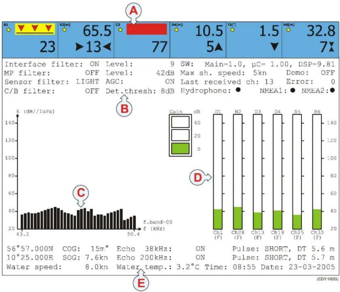
bar
| Parameter | Value | | :--- | :--- | | Interface filter: ON Level: 9 SW: Main=1.0, μC= 1.00, DSP=9.81 MP filter: OFF Level: 42dB Max sh. speed: 5kn Demo: OFF Sensor filter: LIGHT AGC: ON Last received ch: 13 Error: 0 C/B filter: OFF Det.thresh: 8dB Hydrophone: NMEA1: NMEA2: ● | | Gain | dB | | D1 | 140 | | H2 | 140 | | D3 | 140 | | D4 | 140 | | S5 | 140 | | B6 | 140 | | Ch1 (F) | 40 | | Ch28 (F) | 40 | | Ch13 (F) | 40 | | Ch19 (F) | 40 | | Ch25 (F) | 40 | | Ch30 (F) | 40 | | 56°57.000N COG: 15m° Echo 38kHz: ON Pulse: SHORT, DT 5.6 m 10°25.000E SOG: 7.6kn Echo 200kHz: ON Pulse: SHORT, DT 5.7 m Water speed: 8.0kn Water temp.: 3.2°C Time: 08:55 Date: 23-03-2005 (CD11102G)Informationfields
TheinformationprovidedbytheStatusdisplaycanbedivided intofivefields:
(A)=Numericinformationfromthesensors
(B)=Upperstatusfield
(C)=Frequency spectrum for noisemonitoring
(D)=Gainindicatorsforthecurrentsensors
(E)=Lowerstatusfield
(A) Numericinformation
ThenumericdisplaysatthetopoftheStatusdisplayprovide thecurrentinformationfromtheactivesensors.Duetothelack ofspace,theinformationfromthesensorshavebeen abbreviatedslightly.Foramoredetailedpresentation,youmust selectthetheNumericdisplaypresentation.
(B) Upperstatusfield
Theupperstatusfieldprovidesanoverviewofkeyparameters.
Receiversetup: All the parameters on the left side are those defined by the Receiversetup dialogue. To change these, press the MENU button to access the Setup menu (4), and select Receiversetup(6).
SW: This sentence provides the current software version in your PI44 system. Main is the operational software providing the user interface, C is the PI44 microcontroller, while DSP is the software controlling the digital signal processor, that is the reception and interpretation of sensor information.
Maxsh.speed: This isthemaximumshootingspeedas defined in the Receiversetupdialogue.
Demo: Thisentryshowsyouifthesensordemonstrationmode has been activated. ToswitchtheDemomodeonoroff, access theSensorsetup.
Lastreceivedch: Thisentryshowsyouwhichofthesensors thatlastprovidedinformationtothePI44.
Error: Thisissimplyanerrorcode. Thisinformationis provided for test purposes only. Unless as software error occurs, the codewill be 0 (zero).
Hydrophone: Ayellowindicatorisprovidedwhenthe hydrophoneisconnectedandfullyoperational.Iftheindicator isred,ashortcircuithasoccurred.Iftheindicatorisblack,the PI44haslostelectricalcontactwiththehydrophone.
NMEA1/2: AnyinformationacceptedbytheNMEAinterface willprovideagreenindicator.Iftheindicatorisblack,thePI44 iscurrentlynotreceivinginputtraffic,however,information maystillbeexportedcontinuously.
(C) Frequency spectrum
Thisgraphprovidesyouwithininformationaboutthebackground noiseandthesignalstrengthofthefrequencybandorchannel numberselected.Eachverticalbarrepresentsthebackground noiseforthegivenfrequencyorchannel,andthelevelis measuredcontinuously.
Toselectspectrumdisplay, presstheADJbuttontoopenthe Status setup dialogue, and select Spectrum, display to show Frequency or Channel. In most cases a Channel view will be mostusefultoyou.
Thisfunctionisveryusefulifyouhavetoomuchnoiseandthis makesthecommunicationwiththesensorunreliable.Switchoff asmuchelectrical,mechanicalandacousticgearandequipment aspossible.Then,switchthesystemsonagainonebyonewhile keepinganeyeonthefrequencyspectrum.Whenthe“noisy” systemisactivated,itismostlikelyeasytosee!
Notethatthefrequencyspectrumpresentationdependsonthe Interferencefiltersetting.
(D) Gainindicators
Therearesixgainindicators,oneforeachofthecurrent sensors.Atthetopofeachindicatoryoucanseesensornumber andsensortype,atthebottomyoucanseethesensor's communicationchannelandcurrentupdaterate.Greencolour indicatesthatthereceptionofsignalsandnoiseiswithinnormal specifications.Redcolourindicatesthatthereceivedsignal exceedstheminimumlevelrequiredforreception,thisis thereforenotanerrormessage.
Forthetechnicalminded: Whennosensorshavebeendeployed, theindicatorswillpresentthemeannoiselevel. Thisisthenoise inthesurroundingwater, causedbymechanical, electrical, acousticandnaturaldisturbances. Thisnoiselevelshouldbeas lowaspossible. Whenasensorinthewatertransmitsits informationbacktothePI44, thisisindicatedasthegreen indicatorextendsabovethemeannoiselevel. Inorderforthe receptioncircuitrytoacceptandrecognizethesignal, itmustbe strongerthanapredefinedminimumlevel. Thelevelisnormally referredtoasthedetectionlevel. Ifthesignalisstrongerthan thedetectionlevel, theindicatorbarwillchangecolourtored.
(E) Lowerstatusfield
Thelowerstatusfieldprovidesanoverviewofkeyparameters.
Geographicallocation: At the left side of the field, the current geographic location is provided. Not that this information can only be displayed if a positioningsystem has been connected to the PI44.
COG: Currentcourseoverground. Notethatthecourse informationcanonlybeprovidediftherelevantsensor(GPS) hasbeenconnectedtothePI44.
SOG: Currentspeedoverground. Notethatthespeed informationcanonlybeprovidediftherelevantsensor(GPS) hasbeenconnectedtothePI44.
Waterspeed: Currentspeedinthewater. Notethatthespeed informationcanonlybeprovidediftherelevantsensor(GPSor speedlog)hasbeenconnectedtothePI44.
Echo38kHz: Thisentryprovidesthecurrentstatusofthelow frequencyechosounder,aswellasitscurrentpulselengthand detectionthreshold.
Echo200kHz: Thisentryprovidesthecurrentstatusofthehigh frequencyechosounder,aswellasitscurrentpulselengthand detectionthreshold.
Watertemp: This entry provides the current watertemperature. Notethat this information can only be provided if therelevant sensor have been connected to the PI44.
Timeanddate: Thisentryisareadoutofthecurrenttimeand date.
Related topics
→ Receiversetup,page208
→ Statussetup,page218
Echo sounder display
ThePI44offersanaccurateechosounderwithacolourdisplay. Theechosoundercanoperateon38,50or200kHz,andwith twofrequenciessimultaneously.Inordertoenjoytheecho sounderfunctionality,youmusthaveoneortwoechosounder transducersinstalled.
Notethatsomeoftheinformationprovidedbytheechosounder presentationassumesthatyouhavetherelevantsensors connectedtoyourPI44system.
Theechosounderdisplaycanbesetupasafullscreenfeature, butyoucanalsosetituptobedisplayedinsmallerwindows. Dependingonthewindowsize,theechosounderdatamaybe shownwithdifferentlayouts,andevenwithsomeofthe informationremovedduetothelimitedspaceavailable.
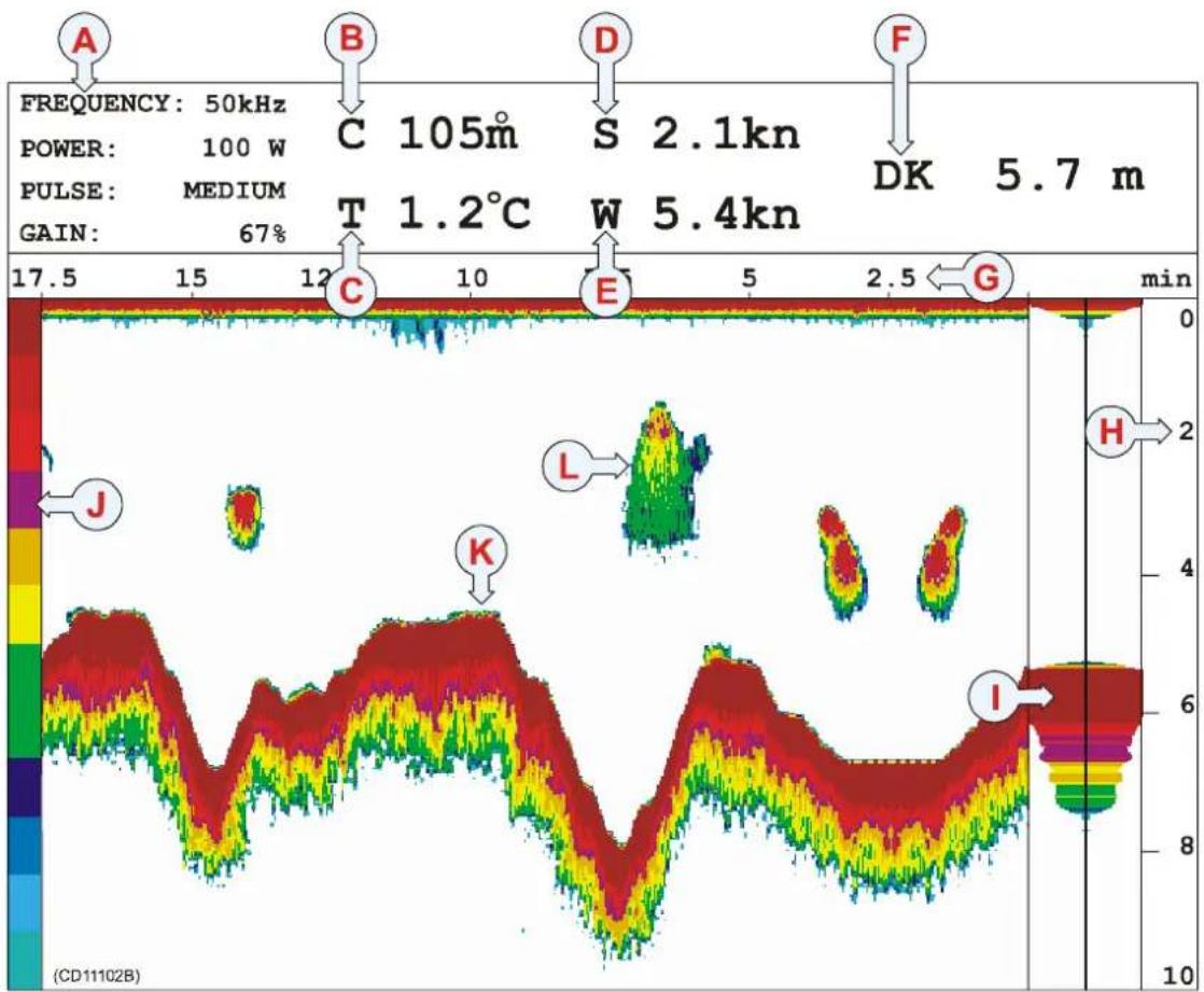
heatmap
| Point | Value | |-------|-------| | A | 50kHz | | B | 105m | | C | 1.2°C | | D | 2.1kn | | E | 5.4kn | | F | 5.7 m | | G | - | | H | - | | I | - | | J | - | | K | - |The following information is provided in the echosounder presentation.
(A)Currentprimarytechnicalparameters.
(B)Currentcourse.
(C)Currentambientairtemperature.
(D)Currentvesselspeed
(E)Currentwindspeed
(F)Depthunderkeel
(G)Timescale: Elapsed times in cesounding (ping). Notethat the timescale will changed depending on the chosen scrolls speed.
(H)Depthscale: This scale can be set up change automatically depending on the current depth.
(I)A-scopepresentation.
(J)Colourscale. This scales show the echoes are presentes, The strongest echoes are displayed using the colour on the top of the scale, while the weakest echoes are displayed using the colours at the bottom of the scale.
(K)Bottomecho
(L)Fishecho
Thepresentationiscontrolledbytheparametersdefinedinthe presentationsetup. Tochangetheseparameters, press the ENT button to open the Echo quick menu, and choose Echo presentationsetup. Tochangepresentationunits, press the MENUbuttontoopenthemainmenu, and thenselectSpeed alarm, units and settings on the Setup menu.
IntheEchosoundersetupyoucanchangethereadoutfor currentdepth(F),andyoucandisablethetimescale. These setupparametersareavailableontheSetupmenu.
Bottomexpansion
ThePI44providesaBottomexpansionfunction. Whenenabled the vertical area aclosetotheseabedisexpanded. Theresulting presentationwillnotshowthedepthvariations, asthebottom willappearflat. However, echoesclosetothebottomwillbe enhanced. Notethatthedepthrangeinthispresentationwillbe "upsidedown", astheseabedisdefinedaslevel "0".
To enable the Bottom expansion function, press the B-LCK buttononthekeypad.Todisableit,presstheSTNDbutton.The verticaldepthrangeofthebottomexpansionfunctionis controlled by the Expansion window parameter in the Echo presentation setup. Press the ADJ button to access this setup page.
A-Scope
The PI44 provides an A-Scope function. This presentation provides the echo from the latest ping only. The strength of the returned signal from various depths in the water column are indicated by the horizontal deflections from the Y-axis. This presentation is very useful to you wish to search for single fish, asthose echoes are hard to see on theregularechogram. Also, the presentation will give an indication on how strong the various echoes are.
To enable this function, press the ENT button to open the Echo quick menu, and select Activate A-Scope. To disable it, select HideA-Scopeonthesamemenu.
Tochangepresentationparameters
Theechosounderpresentationiscontrolledbytheparameters definedinthesetup.Tochangetheseparameters,makethe presentationwindowactive,andpresstheADJ(Adjust)to accesstheEchopresentationsetuppage.Youcanalsopress the ENT key to access the Echo quick menu, and select the Echopresentationsetupthere.
Thetechnicalparametersfortheechosounderarelocatedonthe Echo sounder setup page. To access, press the MENU button, and select Echo sounder setup on the Setup menu.
Related topics
→ Echopresentationsetup,page177
→ Echosoundersetup,page180
Highway display
ThenavigationdisplayprovidedbythePI44offersallkey informationrelatedtowaypointnavigation.Notethatthe informationprovidedbythispresentationassumesthatyouhave therelevantsensor(GPS)connectedtoyourPI44system.
Thenavigationdisplaycanbesetupasafullscreenfeature, but youcanalsosetituptobedisplayedinsmallerwindows.

The following information is provided by thenavigation display:
(A)“C”isthecurrentcourse overground,while“B”isthe coursetothenextwaypoint.
(B)“X”isthecross-trackerror, while “D”isthedistancetothe nextwaypoint.
(C)"S"isthecurrentspeed overground,while“V”isthe speedtowardsthenext waypoint.
(D) These are the cross-track error alarmlines.
(E)Theidealcourseline betweenthetwowaypoints.
Tochangepresentationparameters
Thepresentationiscontrolledbytheparametersdefinedinthe PI44 setup. To change these parameters, press the ADJ or ENT buttontoopentheNavigationsetuppage.
To access the Pilot/Position parameters, press the MENU button to access the main menu. Then select Pilot/Position Setup on the Setup menu.
Related topics
→ Navigationsetup,page200
→ Pilot/Positionsetup, page200
Position display
The Position display provided by the PI44 offers all key informationrelatedtosafenavigationononedisplay presentation. NotethattheinformationprovidedbythePosition displayassumesthatyouhavetherelevantsensors(GSPand temperaturefeeler)connectedtoyourPI44system.
The Positiondisplaycanbesetupasafullscreenfeature, but youcanalsosetituptobedisplayedinsmallerwindows.
| Water temp2.3°C | Log 1125.3nm | Log 20.0nm |
 | ||
  |   |   |
 |  |  |
The following information is provided by the position display:
Watertemperature:The temperaturewillonlybe availableiftheapplicable temperaturefeelerisconnected tothePI44.
Twoindividualdistancelogs: Bothdistancelogscanbereset usingthesetupparameters.
Currentgeographical position: If the position fail to be updated, the characters will flash.
Currentspeed,courseanddepth: This information will only be available if the applicable sensor have been connected to the PI44.
Localtimeanddate
ExternalPOS: This is the current status of the satellite reception. The character "A" means that thereception is good, "B" means that thereception is acceptable, and "C" means that it is poor. If there is no reception, the message Not valid will be shown.
Tochangepresentationparameters
Thepresentationiscontrolledbytheparametersdefinedinthe PI44 setup. To change these parameters, press the ADJ or ENT buttonstoopenthePositiondisplaysetuppage.Toaccessthe Pilot/Position parameters, press the MENU button to access the main menu. Then. select Pilot/Position Setup on the Setup menu.
Related topics
→ Positiondisplaysetup,page206
→ Pilot/Positionsetup, page200
OPERATIONAL PROCEDURES
Overview
Thischapterwillprovideyouwithbasicproceduresinorderto helpyousetupthemostcommonfunctionsandparametersin thePI44.
Sensor procedures
→ Howtoshoworhidethegraphic alarm, page56
→ Howtoshoworhidethesensortimers, page56
→ Howtoresetthesensortimers, page56
→ Howtochangebackgroundcolour, page56
→ Howtosetupthesensors, page58
→ Howtomountthesensorsonthenet, page61
→ Howtousethesensors, page62
→ Howtoreplacethesacrificialwater switch, page63
→ Howtotestthesensors,page64
→ HowtocalibratetheDepthsensor, page65
→ Howtodefinesensoroffsets,page66
→ HowtosetupaSpreadsensorfora twintrawl, page67
→ HowtosetupaSpreadsensorfora dualtwintrawl, page72
Graphic display procedures
→ Howtoaccessgraphicdisplay
parameters, page79
→ Howtoviewechosounderdata, page80
→ Howtosetupmarkerlines,page81
→ Howtousethespecialfeaturesfor trawlmarkers, page86
Echo sounder procedures
→ Howtoaccessechosounder parameters, page88
→ Howtousevisualaidsandfilters, page89
→ Howtodefinerange,page91
→ Howtozoominonbottomechoes, page93
→ Howtozoominonpelagicechoes, page94
→ HowtoactivatetheA-Scope
presentation,page95
Common procedures
→ Howtodefinealarmlimits, page96
→ Howtoselectmenulanguage,page99
→ Howtocontrolautomaticpage
rotation, page100
→ Howtorestoredefaultsettings, page 101
→ Howtopersonalizeyoursystem, page102
How to define sensor presentation
The information from the various sensors are provided by the Numerical display, where each sensor is presented in its own rectangular data winsow.
How to show or hide the graphical alarm
1 Ensure that you have a Numeric display presentation in youractivewindow.
2 Press the ADJ button to open the Numeric setup dialogue.
3SwitchShowgraphicalarmonoroff.
4 Press the ENT button to save the parameters and exit.
Howtoshoworhidethesensortimers
Sensor timers are only used on Catch and Bottom Contact sensors.
1 Ensure that you have a Numeric display presentation in youractivewindow.
2 Press the ADJ button to open the Numeric setup dialogue.
3SwitchSensortimeronoroff.
4 Press the ENT button to save the parameters and exit.
How toresetthesensortimers
Sensor timers are only used on Catch and Bottom Contact sensors.
1 Ensure that you have a Numeric display presentation in youractivewindow.
2 Press the ADJ button to open the Numeric setup dialogue.
3SetResetsensortimersto YES.
4 Press the ENT button to save the parameter and exit.
5 Press the ENT button one more time to accept the process.
ThenexttimeyouaccesstheNumericsetupdialogue,thevalue forResetsensortimersisNO.
Howtochangethebackgroundcolour
Youcanchangethebackgroundcoloursontherectangulardata windowsinordertoeasilydistinguishthemfromeachother.
1 Press the ENT button to open the manin menu.
2 On the Setup menu, select Palette setup.
3Observethefirstpalettepageappear.Itcontainsfixed colours,whichcannotbealtered.Pressthe+button repeatedlyuntilyoureachacustompage.
4 By means of the circular Selector pad and the + and - buttons, select therequested colour(s).
5 Press the ENT button to accept the choice.
Related topics
→ Numericsetup,page202
→ Numericdisplay,page33
How to set up the sensors
The very first time you switch on the PI44, you will need to set up the sensor configuration. This will also be required if you perform a “master reset” on the PI44, and then reload the manufacturer’s default settings.
Observethe following procedure to establish them most common values. Formoredetailed information about these settings, refer to the References chapter.
Note: Inordertoestablishthesensorconfiguration,youneedtoknow whatkindofsensorsyouhave,whichchannelsthey communicateon,andhowoftentheycommunicate.This informationisrequiredbeforeyoustarttheconfigurationonthe PI44.
Note: Donotattempttosetupthesensorsunlessthisisabsolutely necessary.
Westronglysuggestthatyouusetheformsinthefrontofthis manualtowritedownthesensoryouhavewithinformation abouttheirupdateratesandcommunicationchannels.
1 Press the MENU button to open the main menu.
2 Open the Setup menu (4), and select Sensor setup (5).
3 Press the ENT key to bypass the warning page.
4Foreachofthesensorsyoushalluse,selectthefollowing parameters:
a Set Sensor type to SINGLE to activate the sensor.
b Set Update rate FAST, SLOW or NORMAL
c Set Measure to chosen sensor type.
d Set Channel to correct communication channel for the chosensor.
5 For operational use, make sure that Demo mode is set to OFF.
6Whenyouhavedefinedthesensors,presstheENT buttomtosavethechangesandexit.
If you configure less thens six sensors, you will be able to set the Sensor parameter to Dual. You can not use this setting. Dual sensors are not yet available, and this functionality is not yet supported by the digital signal processing in the PI44. The ability to choose Dual is implemented for future expansion only, and any attempt to choose this setting will not work.
Predefinedsettings
Eachsensorisdeliveredwithapredefinedsetup.Thissetup includes:
- transmissionchannelfortheacousticcommunicationlink betweenthesensorandthevessel'shydrophone
- updaterate;howoftenthesensorsendsitsreadingsbackto thePI44system.
Tochangethesensorsetup,youcancallyourlocalSimrad dealer,oryoucandoityyourselfifyouhavetheproper equipment,trainingandthePIConfiguratorsoftware.
Changingatransmissionchannel
It may be required to change one more or more transmission channels, and there may be many reasons for this.
- You havemorethanoneofeachsensor. Forexample, if you havethreetemperaturesensors, they MUST communicate on threedifferentchannels.
- OthervesselsnearyourusethesamePI44system(ora similar), and they have one more of their sensors set up to the same communication channels as you have. This will create interference, as you will "read" each others sensors.
- Ifyoursensorsaresetuptousecommunicationchannelstoo closetoeachother(forexample,youhavechosenchannels 4,5and6),thiswilllimitthevessel'sspeed.Thereasonfor thisisthedopplereffect.Ifthespeedistoohigh,thedoppler willcausethetransmissionfrequenciestochangesomuch thattheyoverlap,andthiswillcreateinterference.ThePI44 willprovideawarningifthisisabouttohappen!Youmust theneitherchangetoothercommunicationchannelsfurther apart,orreducethemaximumshootingspeed.
- If you operate at the maximum range of the sensors, you may be able to increase this ranges slightly if you use lower communication channels. This is because the lower communication channels user lower transmission frequencies.
Changingtheupdaterate
Itmayberequiredtochangetheupdaterateonasensor, that is how oftenitsendsinformationback to the PI44 system. A high updaterate will give frequent information updates, but the sensor will use more battery power. If you need your batteriesto last as long as possible, you must consider lowering the update rate.
- Alowupdaterate will provide you with fewer information updates, but the battery will last very long.
- Ahighupdateratewillgiveyoufrequentinformation updates,butthebatterywillrunoutfaster.
AllsensorsareprovidedfromSimradwithadefaultupdaterate setting.Insomecasesyoumayfindthatthisupdateratedoes notsuityouroperationalneeds.Thisisadecisionyouhaveto madedependingonthelocalfishingconditions.
Howtochangethesensorsetup
Tochangethesensorsetup,youcancallyourlocalSimrad dealer,oryoucandoityyourselfifyouhavetheproper equipment,trainingandthePIConfiguratorsoftware.
Related topics
→ Sensorsetup,page215
→ Maxshootingspeed, page208
→ PICoufigurator,page226
How to mount the sensors on the net
Oncethesensorhasbeencodedcorrectly,youmustmountiton thenet. Themountinginstructionsforeachsensorisprovidedin theSensorschapter,andthesameinformationcanalsobefound ontheQuickReferenceGuideforeachsensor.
Related topics
→ Sensorsoverview,page103
How to use the sensors
Oncethesensorshavebeencodedandinstalledonthenet,they willautomaticallybeswitchedononcetheyaresubmergedinto water.ThePI44willthenautomaticallyretreiveinformation fromthem,andprovidedthatyouhavechosenthecorrect displaypresentation,theinformationwillbeprovidedtoyou.
Applications
The various applications available to you with the different sensors are explained in the Getting started and Applications chapters.
Displaypresentation
Howtosetupthedisplaytoseetheinformationprovidedbythe sensorsaredescribedintheGettingstartedchapters.The variousmodesareexplainedindetailintheDisplaymodes chapter.
Practicalinformation
Thepracticalinformationaboutthevarioussensorsisprovided intheSensorschapter,andthesameinformationcanalsobe foundontheQuickReferenceGuideforeachsensor.
Related topics
→ Gettingstarted:Presentationpages,page13
→ Gettingstarted:Sensors,page20
→ Applications, page25
→ Sensorsoverview,page103
How to replace the sacrificial water switch
AllPIandPSsensorsareequippedwithawaterswitch,andtwo differenttypesareused.Ifyoursensorsareequippedwitha brassscrew,observethefollowingprocedureforreplacement.
1Turnthesensorupsidedown,andlocatethebrassscrew.
2Inspectthescrewforwearandtear.Ifrequired,replace thescrew.
Astandardcommercialbrassscrewisused. Localsupplywill normallybeavailable, butthefollowingspecificationsmustbe met:
Brass,SizeM5x10,DIN85A,roundedhead

natural_image
Close-up of a brass-colored metal screw with threaded shaft and flange (no text or symbols visible)Beforeanewscrewisinserted, AquaShield (orasimilar underwaterlubricant) must be applied. Duetothesize of the tube, were recommend that the grease is applied from asyringe.
1 Apply Aqua Shield to the screw threads.
2Insertthescrew,mountfirmly,butnottoohard.
3Usemaximumtorque1.5NM
ApackwithtenscrewsandatubeofAquaShieldcanbe orderedfromSimradasasparepartskit.
AquaShieldismanufacturedbyD.A.Stuart,Warrenville, Illinois,USA(www.d-a-stuart.com).
How to test the sensors
By using the PI Configurator, you can test the operational status of each sensor. Test procedures for all the sensor have been provided in a separate chapter in this manual.
NotethatPIandPSsensorsaretestedusingthesame procedures.
Related topics
→ PICoufigurator,page226
→ Testprocedures, page265
How to calibrate the Depth sensor
Only the Depthsensor can be calibrated. The purpose is to ensure that the depth reported by the sensor as accurate as possible.
Thisprocedureiscarriedoutonboardthevessel.
1Mountaropetothetopfasteninglugsonthesensor.
2 Tightentherope, and measure onemeter from the bottom of the sensorto aspotontherope. Place a visual marker on the orope at that location.
3Lowerthesensoroverthesideofthevesselandintothe water. Lowerituntilthevisualmarkerontheropeiseven withthesurface.
4OnthePI44,observethnumericalpresentationofthe sensor,andallowthereadingtostabilizeitself.
5 On the PI44, press the MENU button to open the Main menu.
6 Press 4 to open the Setup menu, and 4 again to open the Sensoralarm/calibrationdialogue.
7PresstheGAIN+buttonthree-3-timestoaccessthe Depthcalibrationdialogue.
8 Set Depth sensor calibration to YES.
9 Press the ENT button to accept the choice, and one more timetoacknowledge.
10 Observe the information page. Press the ENT button once againtoproceed.
11Leavethesensorhangingfromtheropeforminimumtwo minutes.Meanwhile,observethatthenumerical presentationshowsgreycharactersonly.
12OnthePI44, observethatthenumericalpresentationof theDepthsensorisstable,andshows l meter.
13Retrievethesensorfromthewater.
Note: Inordertocalibratethesensor, it must be submerged in salt water.
Youmaywishtouseadifferentdepthreferencethanthesea surface. If thisisthecase, changethemarkingontheropetofit youpreference, forexamplethedepthofthekeelorthedepthof anechosoundertransducer.
Related topics
→ Howtodefinesensoroffsets, page66
→ Depthcalibration,setup,page176
How to define sensor offsets
Only the Depth and Spreadsensors can have their offset values adjusted. The purpose is to allow you to compensate for known deviations.
YoumaywishtoinsertaDepthsensoroffsettolineupthe depthreadingsfromthesensorwiththosefromyourecho sounder.IftheechosoundertransducerislocatedXmeters belowthesurface,theDepthsensorshouldhavethesameoffset value.
Note: If you have performed a Depth sensor calibration, you will see than an offset value may already be present. This value has been provided by the calibration routine.
1 On the PI44, press the MENU button to open the main menu.
2 Press 4 to open the Setup menu, and 4 again to open the Sensoralarm/calibrationdialogue.
3PresstheGAIN+buttonfour-4-timestoaccessthe Offsetadjustdialogue.
4Entertherequiredvalues.
5 Press the ENT button to save the parameters and exit.
Related topics
→ Offsetadjust, setup, page203
How to set up a Twin Spread sensor for twin trawl applications
BymeansoftheTwinSpreadsensor,youcansetupyourPI44 tomonitortheopeningsonatwintrawl.ApartfromtheTwin Spreadsensor,youwillalsoneedtwoRemotesensors.
Sensorconfiguration
The Twin Spread and Remotesensors are supplied in sets, and they MUST operate in thesesets. These are:
- Twin Spread 1 uses two Remote sensors; Remote 1 and Remote3.
- Twin Spread 2 uses two Remote sensors; Remote 2 and Remote4.
Whensuppliedfromthemanufacturer, all TwinSpreadsensors aresetupasTwinSpread1. If youwishtouseaTwinSpread2, yourdealer(oryourself)mustreconfigurethesensorusingthe PIConfiguratorapplication.
Communicationchannelsandupdaterate
EachTwinSpreadsensorwillcommunicateontwochannels, oneforeachofthetwodistancesthesensormeasures. By default, these communication channels are set to 02 and 07.
• Channel 02 is used to measure the distance to Remote 1.
• Channel 07 is used to measure the distance to Remote 3.
Bydefault, both communication channels a resetup with Fast updaterate. In order to increase the lifetime between each sensor charging, you may consider changing to Normal update rate.
If you wishtore configure the settings, your dealer (ory yourself) must us the PIC configurator application.
Placingthesensorsonthetrawl
The TwinSpread sensor must be mounted on the port trawl door, and the three communication transducers on the sensor must not be obstructed. Ensure that you have a clear line of sight between the tip of the Twin Spread sensor and the vessel, and between the Twin Spread sensor and the two Remote sensors.
Remote1isplacedonthecentreclump.
Remote3isplacedonthestarboarddoor.
This configuration will allow the TwinSpreadsensortomeasure the distance from the port doorto the centre clump directly. It will also measure the distance between the two trawldoors. In ordertocalculatethedistance between the centre clump and the starboarddoor, you must perform there required settings on the PI44.

flowchart
graph TD
    A["Source C"] --> B["Detector D"]
    B --> C["Detector E"]
    B --> D["Detector F"]
    D --> E["Detector P"]
    D --> F["Detector S"]
    style A fill:#f9f,stroke:#333
    style B fill:#ccf,stroke:#333
    style C fill:#cfc,stroke:#333
    style D fill:#fcc,stroke:#333
    style E fill:#ffc,stroke:#333
    style F fill:#cff,stroke:#333
    note right of B: Light beam direction (up arrow)
    note right of D: Light beam direction (down arrow)
(P)=Porttrawl
(S)=Starboardtrawl
(C)=PorttrawldoorwiththeTwinSpread1sensormounted.
(D)=CentreclumpwithRemote1mounted.
(E)=StarboardtrawldoorwithRemote3mounted.
(F) = Forward
(1)=Distancebetweenporttrawldoorandcentreclump, measureddirectlybytheTwinSpreadsensor.
(2)=Distancebetweenthecentreclumpandthestarboard trawldoor,mustbecalculatedbythePI44system.
Sensorsetup
ObservetheprocedurebelowtosetupaTwinSpread configurationwithitsdefaultsettings.
In this procedure, sensors1 and2 are used, and no others sensors are shown. Dueto the fact that the Twin Spread sensor occupy two communication channels, the setup program requires that is configured as if it was to separate sensors, but not necessarily sensors1 and 2. Theremaining four channels can be used for others sensors.
Westronglysuggestthatyouusetheformsinthefrontofthis manualtowritedownthesensoryouhavewithinformation abouttheirupdateratesandcommunicationchannels.

1 Press the MENU button to open the main menu.
2 Open the Setup menu (4), and select Sensor setup (5).
3 Press the ENT key to bypass the warning page.
4ToconfiguretheTwinSpreadsensor,enterthefollowing parameters:
a Set Sensor 1 type to SINGLE to activate the sensor.
bSetUpdate1ratetoFAST.
cSetMeasure1toSPREAD.
dSetChannelto02.
e Set Sensor 2 type to SINGLE to activate the sensor.
fSetUpdate2ratetoFAST.
gSetMeasure2toSPREAD.
hSetChannelto07.
5 For operational use, make sure that Demo mode is set to OFF.
6Whenyouhavedefinedthesensors,presstheENT buttomtosavethechangesandexit.
According to the sensor locations previously described, Spread 1 will now measure the distance from the port trawldoorto the centre clump, while Spread2 will measure the distance from the port trawldoorto the star board trawldoor.
Readoutadjustments
ItisnecessarytosetcertainparametersinordertohavethePI44 tocalculatethedistancefromthecentreclumptothestarboard trawldoor.

1 Press the MENU button to open the main menu.
2PresstheWINbuttontoselectafullscreenpresentation.
3 Open the Fishery menu, and select a Graphic display.
4 Press the ADJ button to open the Graphic setup.
5 Press the PAGE+ button three -3- times to access the Trawlinfodialoge.
6 Locate the Clump sensor setting, select SPREAD 1.
-Aspreviouslydefinedanddescribed,sensorSpread1 measuresthedistancebetweentheporttrawldoorand thecentreclump.
7 Locate the Door sensor setting, select SPREAD 2.
-Aspreviouslydefinedanddescribed,sensorSpread2 measuresthedistancebetweentheportandthe starboardtrawldoors. ThissettingallowsthePI44to calculatethedistancebetweentheclumpandthe starboardtrawldoor.
8 Locate Trawl data in additional info, select ON.
9 Locate Type of trawl data, select SPREAD.
10 Press the ENT button to save the settings and exit.
Readouts
Following the configuration and readout adjustment explained, the following readouts are now available in the Graphic display.
- Numeric display: Rectangle S1 shows the distance between theporttrawldoorandthecentreclump.RectangleS2 shows thedistancebetweentheporttrawldoorandthestarboard trawldoor.
- Additionalinformation:Theinformationbardirectlybelow thenumericrectanglesdisplaytheabbreviationTSanda value.Thisvaluerepresentsthedistancebetweenthecentre clumpandthestarboardtrawldoor.
Related topics
→ TwinSpread,page148
→ Sensorsetup, page215
→ Trawlinfo, page223
How to set up two Twin Spread sensors for dual twin trawl application
BymeansoftwoTwinSpreadsensors,youcansetupyourPI44 tomonitorthefouopeningsonadualtwintrawl.Apartfrom thetwoTwinSpreadsensors,youwillalsoneedfourRemote sensors.

(A)=TwintrawlAlpha(Port)
(B)=TwintrawlBravo(Starboard)
Sensorconfiguration
The Twin Spread and Remotesensors are supplied in sets, and they MUST operate in thesesets. Thesets are:
- Twin Spread 1 uses two Remote sensors; Remote 1 and Remote3.
- Twin Spread 2 uses two Remote sensors; Remote 2 and Remote4.
Whensuppliedfromthemanufacturer,allTwinSpreadsensors aresetupasTwinSpread1.YouwillnowneedtouseTwin Spread2aswell,andyourdealer(oryourself)mustreconfigure aTwinStread1sensorusingthePIConfiguratorapplication.
Communicationchannelsandupdaterate
EachTwinSpreadsensorwillcommunicateontwochannels, oneforeachofthetwodistancesthesensormeasures. By default, these communication channels are set to 02 and 07.
- Channel 02 on Twin Spread 1 is used to measure the distancetoRemote1.
- Channel 07 on Twin Spread 1 is used to measure the distancetoRemote3.
Bydefault, both communication channels a resetup with Fast updaterate. In order to increase the lifetime between each sensor charging, you may consider changing to Normal update rate.
WhenyoureconfigureaTwinSpread1sensortoactasaTwin Spread2,youmustalsochoosetwoadditionalcommunication channels.Youcanchooseanychannelsavailableonyour system.
In this description we will use channels 09 and 11 as follows:
- Channel 09 on Twin Spread 2 is used to measure the distancetoRemote2.
- Channel 11 on Twin Spread 2 is used to measure the distancetoRemote4.
If you wish to configure these settings, your dealer (or yourself) must us the PIC configurator application. Makes sure that the channels you choose are not used by any of your others sensors!

flowchart
graph TD
    A["Component C"] --> B["Component D"]
    B --> C["Component E"]
    B --> D["Component F"]
    D --> E["Component S"]
    style A fill:#f9f,stroke:#333
    style B fill:#ccf,stroke:#333
    style C fill:#cfc,stroke:#333
    style D fill:#fcc,stroke:#333
    style E fill:#ffc,stroke:#333
    subgraph Input
        A
        B
        C
        D
        E
    end
    subgraph Output
        F
        G
        H
        I
        J
        K
        L
        M
        N
        O
        P
        Q
        R
        S
    end
OnlytwintrawlAlpha(port)isshown.
(P) = Porttrawl
(S)=Starboardtrawl
(C)=PorttrawldoorwiththeTwinSpreadIsensormounted.
(D)=CentreclumpwithRemote1mounted.
(E)=StarboardtrawldoorwithRemote3mounted.
(F)=Forward
(1)=Distancebetweenporttrawldoorandcentreclump, measureddirectlybytheTwinSpreadsensor.
(2)=Distancebetweenthecentreclumpandthestarboard trawldoor,mustbecalculatedbythePI44system.
Placingthesensorsonthetrawl
The two twin trawls are referred to as Alpha (port) and Bravo (starboard).
OnthetwintrawlAlpha,theTwinSpread1sensormustbe mountedontheporttrawldoor,andthethreecommunication transducersonthesensormustnotbeobstructed.
Remote1isplacedonthecentreclumpofAlpha.
Remote3isplacedonthestarboarddoorofAlpha.
OntwintrawlBravo, the TwinSpread2 sensormustbe mountedontheporttrawldoor, andthethreecommunication transducersonthesensormustnotbeobstructed.
Remote2isplacedonthecentreclumpofBravo.
Remote4isplacedonthestarboarddoorofBravo.
This configuration will allow the Twin Spreadsensors one each dual trawl Alpha and Bravotome asure the distance from the port doortothecentre clump directly. It will also measure the distance between the two trawldoors.
Inordertocalculatethedistancebetweenthecentreclumpand thestarboarddoor,youmustperformthenecessarysettings on thePI44.Thisishoweveronlypossiblewithoneofthetwin trawls,asthecurrentsoftwareversiondoesnotsupportthis function.
Sensorsetup
ObservetheprocedurebelowtosetupaTwinSpread configurationwiththesettingsdefinedabove.
In this procedure, sensors 1, 2, 3 and 4 are used, and no other sensors are shown. Dueto the fact that each Twin Spread sensor occupies two communication channels, the setup program requires that each sensor is configured as if it was separate sensors, but not necessarily sensors through 4. Theremaining two channels can be used for others sensors.
Westronglysuggest that you use the forms in the front of this manual to writed down the sensory you have within information about their updaterates and communication channels.
1 Press the MENU button to open the main menu.
2 Open the Setup menu (4), and select Sensor setup (5).
3 Press the ENT key to bypass the warning page.
4ToconfiguretheTwinSpreadsensor, enter the following parameters:
a Set Sensor 1 type to SINGLE to activate the sensor.
bSetUpdate1ratetoFAST.
cSetMeasure1toSPREAD.
dSetChannelto02.
e Set Sensor 2 type to SINGLE to activate the sensor.
fSetUpdate2ratetoFAST.
gSetMeasure2toSPREAD.
hSetChannelto07.
i Set Sensor 3 type to SINGLE to activate the sensor.
jSetUpdate3ratetoFAST.
kSetMeasure3toSPREAD.
ISetChannelto09.
m Set Sensor 4 type to SINGLE to activate the sensor.
nSetUpdate4ratetoFAST.
oSetMeasure4toSPREAD.
pSetChannelto11.
5 For operational use, make sure that Demo mode is set to OFF.
6Whenyouhavedefinedthesensors,presstheENT buttomtosavethechangesandexit.
According to the sensor locations previously described, the following measurements are made:
- TwintrawlAlpha(port):Spread1willmeasurethe distancefromtheporttrawldoortothecentreclump,while Spread2willmeasurethedistancefromtheporttrawldoor tothestarboardtrawldooroftheporttwintrawl.
- TwintrawlBravo(starboard):Spread3willmeasurethe distancefromtheporttrawldoortothecentreclump,while Spread4willmeasurethedistancefromtheporttrawldoor tothestarboardtrawldoorofthestarboardtwintrawl.

Readoutadjustments
ItisnecessarytosetcertainparametersinordertohavethePI44 tocalculatethedistancefromthecentreclumptothestarboard trawldoor.
Note: Thisishoweveronlypossibleforonetwintrawl, notforboth.
1 Press the MENU button to open the main menu.
2PresstheWINbuttontoselectafullscreenpresentation.
3 Open the Fishery menu, and select a Graphic display.
4 Press the ADJ button to open the Graphic setup.
5 Press the PAGE+ button three -3- times to access the Trawlinfodialoge.
6 Locate the Clump sensor setting, select Spread 1 (or Spread3)
-Aspreviouslydefinedanddescribed,sensorSpread1 measurethedistancebetweentheporttrawldoorand thecentreclump.
7 Locate the Door sensor setting, select Spread 2 (or Spread4)
-Aspreviouslydefinedanddescribed,sensorSpread2 measuresthedistancebetweentheportandthe starboardtrawldoor.ThissettingallowsthePI44to calculatethedistancebetweentheclumpandthe starboardtrawldoor.
8 Locate Trawl data in additional info, select Yes.
9 Locate Type of trawl data, select Spread.
10 Press the ENT button to save the settings and exit.
Readouts
Following the configuration and readout adjustment explained, the following readouts are now available in the Graphic display.
- Numericdisplay:
- Rectangle S1 shows the distance between the port door and the centreclumpontwintrawlAlpha(port).
- Rectangle S2 shows the distance between the port and starboardtrawldoorsontwintrawlAlpha(port).
- Rectangle S3 shows the distance between the port door and the centre clumpontwintrawl Bravo(starboard).
- Rectangle S4 shows the distance between the port and starboardtrawldoorsontwintrawlBravo(starboard).
- Additionalinformation:Theinformationbardirectlybelow thenumericrectanglesdisplaytheabbreviationTSanda value.Thisvaluerepresentsthedistancebetweenthecentre clumpandthestarboardtrawldooronthechosenport(or starboard)trawl.
Related topics
→ TwinSpread,page148
→ Sensorsetup, page215
→ Trawlinfo,page223
How to access graphic display parameters
The various parameters defining the Graphic display presentation are controlled from the following dialogues:
- Graphicsetup
- Temperature
- Markerline
- Trawlinfo
- Trawlcalculator
Howtousethemostcommonparametersareexplainedin separateprocedures.
Access
1 MakesurethatyouhaveaGraphicdisplaypresentationin youractivewindow.
2 Press the ADJ button to open the Graphic setup dialogue.
3PresstheGAIN+buttonrepeatedlytoopenthevarious setupdialogues.
Related topics
→ Graphicsetup,page184
→ Temperaturesetup,page220
→ Markerlinesetup,page197
→ Trawlcalculator, page221
→ Trawlinfosetup, page223
Howtoviewechosounderdata
WhenyouhavechosentheGraphicdisplaypresentation, you can choose to superimpose the information from the echo sounder. This feature allows you to see where your sensors are located in relation to the bottom and fishechoes. Not that this feature will only work if you have mounted an echosounder transducerto the PI44.
1 MakesurethataGraphicdisplaypresentationisactive.
2 Press the ADJ button to open the Graphic setup dialogue.
3 Locate the setting Superimpose echo sounder, and set the optiontoON.
4 Press the ENT button to save the setting and close the dialogue.
Related topics
→ Graphicsetup,page184
How to set up marker lines
WhenyouhavechosentheGraphicdisplaypresentation,you canchoosetosuperimposetheinformationfromtheecho sounder,andthenaddmarkerlinestoseewhereyoursensors arelocatedinrelationtothebottomandfishechoes.Notethat theechosounderdatawillonlyappearifyouhavemountedan echosoundertransducertothePI44.
The following parameters will affect the waythemarker lines are displayed:
- Width - you can select how thick (in pixels) each marker line shall be.
- Delay-Theechosounderinformationisprovidedbythe transducer,andthistransducerislocatedunderthevessel. Thesensorsarelocatedonthegear,whichmaybepositioned severalhundredmetersbehindthevessel.Toadjustforthis delay,youcanenteravalueforMarkerlinedelay. You must calculatethisvalue(inminutes)basedonthevessel'sspeed, thewirelengthandthedepthofthegear.
Alternatively, you can us the built-in Trawl caluclatorto find the correct delay.
- Colour-Thecolourofthemarkerlineisautomaticallysetto thecurrentNumericdisplaybackgroundcolourforthesame sensor.Tochangethatcolour,youmustaccesstheDisplay colour setup page from the Setup menu.
- Expanded view: With the setting Sensor marker in expansionactive, theDepthandHeightmarkerlines are shownintheexpandedareas(Bottomlock, ZoomandShift), andthuseasiertoread. Thisisausefulfeaturewhenthe sensoristowedclosetothebottom, anditisparticulary importantfortheHeightsensor.
- Markerwhitezone: Whenthissettigisenabled, white pixelsareaddedaboveandunderthemarkerlinetomakeit easiertodistinguishitfromthebackgroundcolours.
- Height marker in main echogram: This setting is special for Heightsensors. If you have a Heights sensor on the top of abottom trawland the traw拉开 is small, it maybe difficult to tell the Height marker from the bottom echo. If this is the case, set this function to Off, and view the Height marker in expanded mode only.
- Heightreference:TheHeightsensormeasuresthedistance fromtheheadropetothebottom.IfyouusethePI44echo sounder, set Height reference to Bottom (default), and the heightmarkerwillfollowthebottomcontour.Ifyoueven definethedelaycorrectly,youwillbeabletoseethetrawlin truemotion.Ifyoudonothaveenactiveechosounder,set Height reference to Surface. The height will then be shown with0mdepthasreference,andthemarkerlinewillappear asancarlystraightlinesomedistancebelow0meters.The distancefromthe0meterlineaddowntothemarkerline willbethecurrentheightofthetrawl.
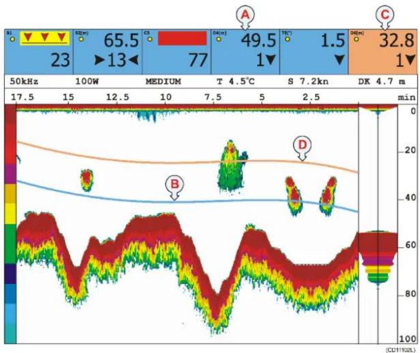
line
| Time (min) | Value | |------------|-------| | 100W | 65.5 | | 13 | 13 | | 4.5 | 77 | | 4.7 | 49.5 | | | 1 | | | 1.5 | | | 32.8 |(A)=Numericdepthdisplay, Sensor "4D" (Depth)
(B)=MarkerlinefromDepthsensor"4D"
(C)=Numericdepthdisplay, Sensor "6D" (Depth). Adifferent background colour has been chosen to tell themarker lines apart.
(D)=MarkerlinefromDepthsensor"6D"
Accesstothemarkerlineparameters
1 Make sure that a Graphic display presentation is active.
2 Press the ADJ button to open the Graphic setup dialogue.
3 Press the GAIN+ button until the Marker line setup dialogueappears.
4 Observethelistofsensors. Onlythesensorscapable of providing dataformarkerlinesarelisted.
Trawlcalculator
Inordertocalculatethecorrectdelay, wesuggestthatyouuse the built-in Trawl calculator. Observe the following procedure:
1 Press the GAIN+ button to access the Trawl calculator setuppage.
2 Set Trawl calculator mode to Auto.
3 Set Towing speed to Auto.
-Inordertoretrievespeedinformation,therelevant equipment(GPS)mustbeinterfacedtoyourPI44.
-WhenyoureadthespeedinformationfromaGPS,the informationisveryaccurate.Duetothefactthatthe trawlcalculationsaremadecontinuously,eventhe slightestchangeinspeedwillbereflectedonthe displaypresentation,andyoumayexperiencethatthe markersfluctuate.Ifthisisaproblem,enterthe averagevesselspeedmanually.
4 If you run a pelagic trawl, set Trawl depth to Manual, and enterthemeandepth.
5 If you run a bottom trawl, you can set the Trawl depth to Bottom, and read the depth from the echosounder.
-IfatransducerisconnectedtothePI44,thetrawl calculatorwillupdatethedelaybasedonthedatafrom theechosounder.
6 Enter the Wire length. In most cases, this is the length fromthesternofthevesseltothetrawldoors.
7 Enter the Wire length offset. This is the distance from the trawldoorstotheheadrope, and normally a fixed value. The calculator will add the wire length to the wire length offset, and uses the sum of these in the calculations.
DepthandHeightmarkerlines
The purpose of these marker lines is to provide an easy way to monitor the depth of the gear. The height sensor measures the distance from these abed and up to the sensor, while the depth sensor measures the distance from these as surface and down to the sensor.
1IdentifywhichofthesensorsthataretheDepthand/or Heightsensors.
2 For each sensor, set Auto to On.
- This enable the PI44 to set the delay calculated by the Trawl calculator.
- You can also set Auto to Off. You must then calculate the delay yourself, and enter it manually in the Delay column.
3 Enter your preferred value for marker line Width.
4 Enable each individual marker line by setting Show to On.
5Ifyouwishtoseethemarkerline(s)inexpandedview (Bottom Lock, Zoom and Shift), set the Sensor marker lineinexpansiontoOn.
6IfyouwishthePI44todrawathinwhitelineoverand underthemarkerlinetoenhancetheview,setMarker whitezonetoOn.
7IfyouwishtoviewtheHeightmarkerinexpandedmode only, set Height marker in main echogram to Off.
8 Select the appropriate setting for Height reference.
9 Press ENT to save the settings and exit to the graphic displaypresentation.
TheDepthandHeightmarkerlinesarepresentedonthe Graphicdisplaywithcontinuouslinesinthesamebackground colourasintheNumericdisplay.Toreadthedepth,consultthe depthrangeontherightsideofthedisplay,orthereadoutinthe Numericdisplay.
Spreadmarkerline
The purpose of this markerline is to provide an easy way to monitor the distance between the trawldors.
1IdentifywhichofthesensorsthatistheSpreadsensor.
2SetthemarkerlinetoON.
3EnterthepreferredsettingsforMarkerlinethickness andMarkerlinedelay.
4 Press ENT to save the settings and return the graphic presentation.
TheSpreadmarkerlineispresentedontheGraphicdisplay withacontinuousline.Thecolourofthelineisthesameasthe backgroundcolourinthenumericpresentation.Toreadthe distancebetweenthetrawldoors,consultthedepthrangeonthe rightsideofthedisplay,orthereadoutintheNumericdisplay. Ifthetrawldoordistanceisreducedorincreased,thiswillbe easilydetectedasthemarkerlinemovesupordown.Notethat youdonotmonitorthedepthofthetrawldoorseventthough youusethedepthscale,thescaleisusedasarangescale.
Surfacetemperaturemarkerline
The purpose of this marker line is to provide an easy way to monitor the surface temperature. Not that this is not a reading from temperatures sensor, but from a feeler. Such feelers are often built into the echosounders transducers.
1 Ensure that a proper feeler is connected to the PI44.
2SetthemarkerlinetoOn.
3EnterthepreferredsettingsforMarkerlinethickness andMarkerlinedelay.
4 Use the ADJ button to open the Temperature setup page.
5 Press ENT to save the settings and exit to the graphic displaypresentation.
The Temperaturemarkerline is presented on the Graphic display as a continuous line.
Related topics
→ Graphicsetup,page184
→ Markerlinesetup,page197
→ Temperaturesetup, page220
→ Trawlcalculator, page221
Special features for trawl marker lines
Whenyouhavechosenagraphicpresentation,youcanchoose tosuperimposetheinformationfromtheechosounder,andthen addmarkerlinestoseewhereyoursensorsarelocatedin relationtothebottomandfishechoes.Whenyouuseapelagic orbottomtrawl,thePI44offerscertainspecialfeaturesto provideadditionalinformation.

line
| Time (min) | Value | |------------|-------| | 13 | 65.5 | | 1 | 49.5 | | 1 | 32.8 |(A)=Numericdepthdisplay, Sensor "6D" placed on the headrope
(B)=Markerlinefromthefootrope,addedbyusingtheManual trawlmarkersetting
(C)=MarkerlinefromtheheadropeusingthedatafromDepth sensor“6D”
Therecommended sensor configuration to monitor the trawl openingistouse one Heightor Depth sensor on the headrope, and one Depth sensor on the footrope. However, if you only use one of these sensors, place it on the headrope. The PI44 will then manually draw the trawl opening markers for you provided that you enter the typical height of the trawl opening.
The following parameters will provide the extrainformation related to trawl markers:
- Headrope and footrope sensors: You need to tell the PI44 whichDepthand/orHeightsensor(s)youhaveplacedonthefootropeand/orheadropeofthetrawl.
- Trawlopeningmode: Thisparameterdecideshowthetrawl openingshallberecreatedonthegraphicpresentation.Ifyou havesufficientsensorsonthetrawlyoumustselectAuto, andthethePI44willautomaticallycalculatethetrawl openinganddrawitaccordingly.Ifyouonlyhaveonesensor onthetrawlopening(DepthorHeightsensoronthe headrope),theManualsettingwilladdanartificialllineon thepresentation.Thedistancefromtheheadropetothe footropemustthenbedefinedmanuallyusingtheManual trawlmarkerparameter.
Accesstotheparameters
1 Makesurethatagraphicpresentationisactive.
2 Press the ADJ button to open the Graphic setup dialogue.
3 Press the GAIN+ button to access the Trawl info setup page.
Setuptheparameters
1 Locate the setting Headrope sensor, and choose the sensor that you have placed on the headrope.
-IfyouhavenoDepthorHeightsensorsonthe headrope,leavethesettingtoNone.
2 Locate the setting Footrope sensor, and chose the sensor that you have placed on the footrope.
-IfyouhavenoDepthorHeightsensorsonthe footrope,leavethesettingtoNone.
3 Observe that the setting for Trawl opening mode is automatically settoAutoorManual.
-If you have sensors placed on both the footrope and the headrope, the PI44 will be able to calculate the trawl opening automatically, and them mode is set to Auto.
-If you have only onesensor, you will need to enter a manual trawl marker.
4If you have only onesensor, enter a value for Manual trawl marker.
-Thisvaluemustrepresenttheactualheightofyour trawlopening,basedonyourknowledgeaboutyour gear.TheinformationwillbeusedbythePI44todraw asecondtrawlmarkerline.
Related topics
→ Graphicsetup,page184
→ Markerlinesetup,page197
→ Trawlinfosetup, page223
How to access echo sounder parameters
The built-inechosounderiseasilycontrolled from separate dialogues.
- The Echo presentation setup dialogue controls the visual parameters, such as Range, Gain, Whiteline and Expansion window.
- The Echosounder setup dialogue controls the operational parameters, such as alarms, sound velocity and transducer selection.
Howtofindthemostcommonparametersareexplainedin separateprocedures. The parametersaredescribedindetailin theReferenceschapter.
Echopresentationsetup
1 Makesurethasty you have an echosounder presentation in your active window.
2 Press the ADJ button to open the Echo presentation setup.
Alternatively, you can press the ENT button to open the Echo quick menu, and then select Echo presentation setup (9).
Echosoundersetup
1 Press the MENU button to open the main menu.
2SelectSetup(4)
3SelectEchosoundersetup(STND).
Related topics
→ Echopresentationsetup,page177
→ Echosoundersetup,page180
How to use visual aids and filters
Whenyouusetheechosounder, severalvisualaidsandfilters areavailabletomaketheechoeseasiertoreadandinterpret.
Pingtopingfilter
This function employs a filter which compares the information from one ping with the information from the previous ping. This will "cleanup" the echogram by removing random noises spikes and interference with nocorrelation with the previous echo. The function will thus make the echoes appear more stable. You can switch this filter on or off.
1 Makesurethatyourechosounderpresentationisactive.
2 Press the ADJ button to open setup dialogue.
3 Locate the Ping to ping filter parameter. Set it to ON.
Colourthreshold
Thisfunctionallowsyoutochoosethenumberofcolourstouse forechogrampresentation.Byswitchingthisfilteronand selectingacolourinthebox,allechocolours“below”the chosencolourwillnotbeshownintheechogram.Youcanthus regardthisasan“echothreshold”whichwillremovethe weakestechoes.
1 Makesurethatyourechosounderpresentationisactive.
2 Press the ADJ button to open setup page
3 Locate the Colour threshold parameter. Set it to ON.
4Selectpreferredcolourinthebox.
Signalthreshold
Thisisanon/offfunction.Whenactivated,itwillremovethe weakestechoesfromthescreen.Thethresholdlevelis automatic.Activatewithcaution,asitmayremovesmallfishor otherweakunidentifiedechoesfromthepresentation.
1 Makesurethatyourechosounderpresentationisactive.
2 Press the ADJ button to open setup page
3 Locate the Signal threshold parameter. Set it to ON.
Depthgrid
When this function is enabled, thin horisontal depthlines will be added to the echogram to easier identify the depth intervals.
1 Makesurethatyourechosounderpresentationisactive.
2 Press the ADJ button to open setup page
3 Locate the Depth grid parameter. Set it to ON.
Scrollspeed
Thisfunctioncontrolshowfastthepresentationshallscroll fromrighttoleftacrossthedisplay.Bydefiningthisspeedyou alsocontrolthetimescale.Ifyouslowdownthescrollspeed, youwillalsoincreasethetimebetweeneachechosounder transmission(ping).IfyouchooseFREEZEthepresentation (andalsotheechosoundertransmissions)willstopaltogether.
1 Makesurethatyourechosounderpresentationisactive.
2 Press the ADJ button to open setup page
3 Locate the Scroll speed parameter. Set it to your preferred value.
Whiteline
Whenenabled, abandinthecurrentechogrambackground colourisinsertedimmediatelybelowthedetectedbottomdepth.
1 Makesurethatyourechosounderpresentationisactive.
2 Press the ADJ button to open setup page
3 Locate the White line parameter. Set it to ON.
Backgroundcolour
Youcanchoosewhichbackgroundcolourtouseonthe echogrampresentation.
1 Press the MENU button to open the main menu.
2SelecttheSetupmenu.
3SelectPalettesetup.
4Observethefirstpalettepageappear.Itcontainsfixed colours,whichcannotbealtered.Pressthe+button repeatedlyuntilyoureachacustompage.
5 Locate the Echogram background, and make the required changes.
6 Press the ENT button to save the changes and exit the setuppage.
Related topics
→ Echopresentationsetup,page177
→ Palettesetup,page205
How to define echo sounder range
Therearetwoparametersforrange:
- Rangestart: This is the upper depth from which the echo sounder will provide its presentation.
- Range: This is the vertical depth range for the echo sounder.
The PI44 also offers a Phased range function, where the Range is fixed, but the Rangestartismodified.
The Range and Range start parameters can be manually controlled from the Echo presentation setup dialogue. In most cases, you will however only use the button on the keypad.
Accesstothedialogue
1 Makesurethasty you have an echosounder presentation in your active window.
2 Press the ADJ button to open the Echo presentation setup.
Thetwoparametersinquestionarelocatedatthetopofthe parameterlist.
Standardmode
Inthismode,theRangestartisfixed.Itisnormallysetto0 meters,andifyowishtouseanothervalue,youmustdefine thismanuallyintheEchopresentationsetupdialogue.
1PresstheSTNDbutton.
2 Press the + and - buttons to change the range, or
3 Press the numerical buttons (1 to 9) to change the range.
4 Press the 0 button to enable Auto range.
Whenyoureachtheupperandlowerrangelimits,theecho sounderwillautomaticallyshifttoAutorange.
Phasedrangemode
In this mode, the Range start is variable, and the Range is fixed.
1PresstheSHIFTbutton.
2 Press the + and - buttons to change the Range start value.
3 Press the numerical buttons (1 to 9) to change the range.
4 Press the 0 button to enable Auto start range.
Youwillseethatdifferentrangesareused,butthevalueforthe Rangestartisalwaysadded.Forexample,ifyousettheRange startto30meters,andtheselectthe250metersrange,the totalrangeachievedisfrom30to280meters.Theupper30 metersarehowevernotshownintheechogram.
Related topics
→ Echopresentationsetup,page177
How to zoom in on bottom echoes
TheBottomLockfunctionsallowsyoutozoominonthe echoesclosesttothebottom.
Whenthisfunctionisactive,theechosounderpresentationis splitintwo.Theupperpartistheordinarypresentation,while thelowerpartshowstheechoesjustabovethebottom.The bottomappearstobeflat,butthismaynotbethecase,asthe zoomedareaisrelatedtothebottom.
ActivateBottomLock
1 Makesurethatyourechosounderpresentationisinan activewindow.
2PresstheB-LCKbutton.
If you were operating the echosounder in Phasedrangemode when you pressed the B-LCK button, the echosounder will automatically switch to Standard mode and use the applicable depth range.
Changetherangeintheexpansionwindow
1 Press the ADJ button to open the Echo presentation setup.
2 Change the Expansion window value.
3 Press the ENT button to save the choice and exit.
De-activateBottomLock
1 Press the STND button to return to Standard mode, or
2 Press the SHIFT button to return to Phased range mode.
Related topics
→ Echopresentationsetup,page177
How to zoom in on pelagic echoes
TheZoomfunctionsallowsyoutozoominonechoesinthe watercolumn.
When this function is active, the echosounderpresentation is split into two. The upper partistheordinary presentation, while the lower part show the expansion window with the echoes over and under are referenced depth.
ActivateZoom
1 Makesurethatyourechosounderpresentationisinan activewindow.
2PresstheZoombutton.
If you were operating the echosounder in Phasedrangemode when you pressed the ZOOM button, the echosounder will automatically switch to Standard mode and use the applicable depth range.
Changethereferencedepth
1 Press “up” and “down” on the Selector pad to change the referenced depth.
The depthyouselect will bestored by the echosounder. The next time you activate the Zoom, it will automatically us this reference value.
Changetherangeintheexpansionwindow
1 Press the ADJ button to open the Echo presentation setup.
2 Locate the Expansion window parameter, and change its value.
3 Press the ENT button save the setting and return to the echosounderpresentation.
De-activateZoom
1 Press the STND button to return to Standard mode, or
2 Press the SHIFT button to return to Phased range mode.
Related topics
→ Echopresentationsetup,page177
How to enable A-Scope presentation
TheA-Scopepresentationprovidestheechofromthelatestping only. Thestrengthofthereturnedsignalfromvariousdepthsin thewatercolumnareindicatedbythehorizontaldeflections fromtheY-axis. Thispresentationisveryusefulifyowishto searchforsinglefish,asthoseechoesarehardtoseeonthe regularechogram. Also,thepresentationwillgiveanindication onhowstrongthevariousechoesare.
ActivateA-Scope
1 Makesurethatyourechosounderpresentationisinan activewindow.
2 Press the ENT button to open the Echo quick menu.
3SelectActivateA-Scope(2).
De-activateA-Scope
1 Makesurethatyourechosounderpresentationisinan activewindow.
2 Press the ENT button to open the Echo quick menu.
3SelectHideA-Scope(2).
How to define alarm limits
ThePI44willprovideavarietyofaudibleandvisiblealarmsto keepyoupostedwhensomethingoccur.
Observethefollowingprocedurestosetupanenablethemost commonalarms.Formoredetailedinformationaboutthesetup pages, refertotheReferenceschapter.
Speedalarm
Thespeedalarmprovidesyouwithanaudiblewarningifthe vessel'sspeedexceedsapredefinedspeedlimit,orifthespeed islowerthanapredefinedminimum.
1 Press the MENU button to access the main menu.
2 On the Setup menu, select Speed alarm, units & language.
3 Move the cursor down the the Speed alarm parameters.
4 Makethenecessary changes, and seteachalarmtoON.
5 Press the ENT key to store the parameters and exit.
Fishalarm
Thefishalarmprovidesyouwithanaudiblewarningiffish echoesaredetectedbytheechosounder. Youcanselectthe alarmsensitivity(howstrongtheechoesneedtobetotrigger thealarm), and youcanalsodefineaverticaldepthareatolimit themonitoredarea.
1 Press the MENU button to access the main menu.
2 On the Setup menu, select Echo sounder setup (STND).
3 Move the cursor down the the Alarm for fish parameter.
4Selectrequiredstrength,andsetthealarmtoON.
5Movethecursortothenextline, andselectaverticalarea forthealarmbyenteringminimumandmaximumdepths.
6 Press the ENT key to store the parameters and exit.
Depthalarm
The depthalarm provides you with a audible warning if the water depth this shallower or deeper than predefined limits.
1 Press the MENU button to access the main menu.
2 On the Setup menu, select Echo sounder setup (STND).
Sensoralarms
Thesensoralarmsprovideyouwithanaudibleandvisual warningifthedatafromasensoreexceedspredefinedlimits.
1 Press the MENU button to access the main menu.
2 On the Setup menu, select Sensor alarm/calibration.
- ObservethattheSensoralarmdialogueopens. In this dialogue, only the sensors currently activated are shown. Each of them provide various alarm functions.
3Selectminimumand/ormaximumlimitsfortheindividual sensors, and activateeachalarmseparately.
4 Press the ENT key to store the parameters and exit.
NotethattheCatch,RipandBottomContactsensorscanonly providealarmswhentheyareactivated,thatiswhentheir detectorwireshavebeenpulledtight.
Surfacetemperaturealarm
Thesurfacetemperaturealarmprovideyouwithanaudibleand visualwarningifthetemperatureexceedspredefinedlimits,or ifitchangestoofast.
1 Press the MENU button to access the main menu.
2 On the Setup menu, select Sensor alarm/calibration.
- ObservethattheSensoralarmdialogueopens.
3 Press the GAIN+ button repeatedly until the Surface temperaturedialogueappears.
4Selectminimumand/ormaximumtemperaturelimitsfor thealarms, and activateeachalarmseparately.
5 Enter the appropriate value for the Shear alarm, and activatethealarm.
6 Press the ENT key to store the parameters and exit.
The Shear alarm will be triggered if the temperature changes faster per minute than the value you have entered.
Note: Inordertoenablethesealarms, your PI44 must have the relevant temperature feeler fitted!
Clearancealarms
The clearance alarm provide you with an audible and visual warning if at raw loranothertowed object either movestoo closeto the bottom, or lift sto of far off the bottom.
1 Verify that the echosounder is operational.
2 Press the MENU button to access the main menu.
3 On the Setup menu, select Sensor alarm/calibration.
- ObservethattheSensoralarmdialogueopens.
4PresstheGAIN+buttonrepeatedlyuntiltheClearance dialogueappears.
5Selectminimumand/ormaximumdistanceforthealarms, andactivateeachalarmseparately.
6 Press the ENT key to store the parameters and exit.
The clearance alarm will take the current depth reading from the echosounder and subtract the current depth reading from the Depthsensor. The calculated depth of the trawlortowed body is then compared to the alarm limits. Dueto the distance between the vessel and the trawl, you will have a completimetomakethe necessary adjustment to avoid damage.
If your Depthsensorismounted to the headrope, you must create a manual depth marker. This is made in the Trawlinfo dialogue.
Related topics
→ Speedsetup,page217
→ Echosoundersetup,page180
→ Trawlinfodialogue, page223
→ Sensoralarmsetup, page212
→ Surfacetemperaturealarmsetup,page213
→ Clerancealarmsetup,page214
How to select menu language
ThemenusonthePI44canbeprovidedinseveraldifferent languages.
Observethefollowingproceduretoselectmenulanguage. For more detailed information about these setuppages, refertothe Referenceschapter.
1 Press the MENU button to access the main menu.
2 On the Setup menu, select Speed alarm, units & language.
3 Move the cursor down the Display text in parameter.
4 Press the + or - buttons to select language.
5 Press the ENT button to store the parameter and exit.
Related topics
→ Pagesetup, page204
How to control automatic page rotation
YoucansetupthePI44toautomaticallyleafthroughthefour displaypages.Eachpagewillthenbeshownasettimebefore thenextpageisbroughtup.
Observethefollowingproceduretosetupautomaticpage rotation.Formoredetailedinformationaboutthesetuppages, refertotheReferenceschapter.
1 Press the MENU button to access the main menu.
2 On the Setup menu, select Speed alarm, units & language.
3MovethecursordownthePAGErotationinterval parameter.
4 Press the + or - buttons to select time interval.
5 Press the ENT button to store the parameter and exit.
6 To start the function, press the PAGE button, and hold it for minimum three seconds.
7 Toswitch the function off, press any other button on the keypad.
Related topics
→ Pagesetup, page204
How to restore default settings
Whenever necessary you can restore the default factory settings on the PI44.
Observethefollowingprocedure.
1 Press the MENU button to access the main menu.
2 On the Setup menu, select Factory settings.
3Selecttheparametersyouwishtoreset.
Caution: If you choose CLR to return to all factory presets, you will need to redefine every single parameter you have made on the PI44. This includes allechosounder settings, sensor selections and setup, system interfaces and alarms.
Related topics
→ Factorypresetsetup,page183
How to personalize your system
YoucansetupthePI44togreetyourwithyourvessel'sname whenyoupoweritup. Observethefollowingprocedure to personalizeyourPI44.
1 Press the MENU button to access the main menu.
2 On the Setup menu, select Quick guide.
3 In the quick guide, press the PAGE+ button until the Vesselnamepageappears.
4Usethekeypadtoenterthevessel'sname.
5 Press the ENT button to store the names and exit.
PRACTICAL USE OF THE SENSORS
ThePI44catchmonitoringcanoperatewithseveraldifferent sensors. In the following, themostimportantinformation regarding installation and use of each sensor is described.
BothPIandPSsensorsaredescribed.ThePIsensorshave longer ranges, they can be “fast-charged” using the PI Charger, andtheywillprovidesomeadditionalfunctionality.Forall otherpracticalpurposesthetwotypesmayberegardedas identical.ThePI44systemwillautomaticallyadapttoandwork withbothtypes,andyoucanalsousePSandPIsensors together.
Topics
→ Sensorconfiguration,page104
→ PIBottomContact,page107
→ PSBottomContact,page111
→ PICatch,page115
→ PSCatch,page120
→ PIDepth,page124
→ PSDepth,page129
→ PIHeight,page134
→ PIRip,page138
→ PISpread&Remote,page143
→ PITwinSpread,page148
→ PITemperature,page153
→ PSTemperature,page159
Related topics
→ Howtosetupthesensors, page58
→ Howtotestthesensors, page265
Sensor configuration
Communicationchannelsandupdaterates
Allsensorsareprovidedfromthefactorywithpre-defined communicationchannelsandupdaterates.
| SensorCom.channelUpdate | erate | |
| PIBottomContact6Normal | ||
| PICatch4Normal | ||
| PIDepth(300m)16Fast | ||
| PIDepth(600m)12Fast | ||
| PIDepth(1000m)10Fast | ||
| PIHeight14Fast | ||
| PISpread | 2Fast | |
| PI Twin Spread | 2 and 7 | Fast |
| PITemperature | 8Fast | |
| Factorydefaultcommunicationchannelsandupdaterates | ||
Changingatransmissionchannel
It may be required to change one more or more transmission channels, and there may be many reasons for this.
- You have more than one of each sensor. For example, if you havethreetemperaturesensors, they MUST communicate on threedifferentchannels.
- OthervesselsnearyourusethesamePI44system(ora similar), and they have one or more of their sensors set up to the same communication channels as you have. This will create interference, as you will "read" each others sensors.
- Ifyoursensorsaresetuptousecommunicationchannelstoo closetoeachother(forexample,youhavechosenchannels 4,5and6),thiswillimitthevessel'sspeed.Thereasonfor thisisthedopplereffect.Ifthespeedistoohigh,thedoppler willcausethetransmissionfrequenciestochangesomuch thattheyoverlap,andthiswillcreateinterference.ThePI44 willprovideawarningifthisisabouttohappen!Youmust theneitherchangetoothercommunicationchannelsfurther apart,orreducethemaximumshootingspeed.
- If you operate at the maximum range of the sensors, you may be able to increase this ranges slightly if you use lower communication channels. This because the lower communication channels user lower transmission frequencies.
Changingtheupdaterate
Itmayberequiredtochangetheupdaterateonasensor, that is how oftenitsendsinformationback to the PI44 system. A high updaterate will give frequent information updates, but the sensor will use more battery power. If you need your batteriesto last as long as possible, you must consider lowering the update rate.
- Alowupdaterate will provide you with fewer information updates, but the battery will last very long.
- Ahighupdateratewillgiveyoufrequentinformation updates,butthebatterywillrunoutfaster.
AllsensorsareprovidedfromSimradwithadefaultupdaterate setting.Insomecasesyoumayfindthatthisupdateratedoes notsuityouroperationalneeds.Thisisadecisionyouhaveto makedependingonthelocalfishingconditions.
Howtochangethesensorsetup
Tochangethesensorsetup,youcancallyourlocalSimrad dealer,oryoucandoityyourselfifyouhavetheproper equipment,trainingandthePIConfiguratorsoftware.
ThePIConfiguratorapplicationisprovidedtoenablelocal sensorconfiguration.Inordertoperformthisconfiguration,you willneedapersonalcomputer(desktoporlaptop)running Microsoft®Windows®2000orWindowsXP®,andaspecial cable.
SpecialconfigurationofPI Spread
The PI Spread sensor is always used with a PI Remote sensor, and these must be configured in a pair in order to make the transverse communication link work properly. In order to allow for additional spread application, you can set two predefined configurations: PI Spread 1 and/or PI Spread 2.
TheRemotesensorsareavailablepre-programmedforthese twopairs,andthesensorsareidentifiedasRemote1and
Remote2.
Thetwopairsmustbeconfiguredasfollows:
| ConfigurationSpreadsensorRemotesensor | ||
| PISpread1PISpread(*)Remote1 | ||
| PISpread2PISpread(*)Remote2 | ||
| (*)=ThesamePISpreadsensorisusedforbothconfigurations.Bydefault,itisprogrammedforPISpread1. If you wish to use it for PI Spread 2, you must re-configure it using thePIConfiguratorapplication. | ||
You can select the communication channels between the PI Spread sensors and the vessel to your preferences.
SpecialconfigurationofPI TwinSpread
The PI Twin Spread sensor is always used with two PI Remote sensors, and these must be configured as a group in order to make the transverse communication links work properly. In order to allow for adual spread application, you can set two predefined configurations: PI Twin Spread 1 and/or PI Twin Spread2.
The Remote sensors are available pre-programmed for these twopairs, and the sensors are identified as Remote1, Remote 2, Remote 3 and Remote 2. The two first (1 and 2) are the same sensors as forthestandardPISpreadapplication.
Thetwogroupsmustbeconfiguredasfollows:
| ConfigurationSpre | adsensorRemotesensors | ||
| PITwinSpread1PIT | winSpread(*)Remote | 1Remote3 | |
| PITwinSpread2PIT | winSpread(*)Remote | 2Remote4 | |
| (*) = The same PI Twin Spread sensor is used for both configurations. By default, it is programmed for PI Twin Spread 1. If you wish to use it for PI Twin Spread 2, you must re-configure it using the PI Configuratorapplication. | |||
YoucanselectthecommunicationchannelsbetweenthePI TwinSpreadsensorsandthevesseltosuityourpreferences.
PI Bottom Contact sensor
Purpose
The PI Bottom Contact sensor detects if a trawl is accidentally liftedofftheseabed,orapurseseineistouchingthebottom.

natural_image
Illustration of a fishing net with a yellow object and a rope, surrounded by fish (no text or symbols)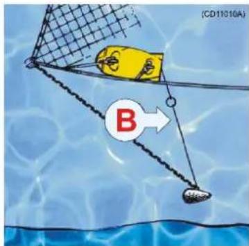
(A)=Thetrawlfollowsthebottom. Thedetectionwireonthesensorisnotreleased.
(B)=Thetrawlhasliftedoffthebottom,andthedetectionwireisreleased.
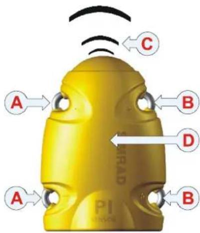
Mainparts
(A)=Negativecharging/fasteninglug
(B)=Positivecharging/fasteninglug
(C)=Communicationlink(Channel1-30)
(D)=Locationofsensorlamp
(E)=Waterswitchsensor
(F)=Detectionwire(in/out)
(G)=Groundweight
Dailyoperation
Onceinstalledandputtouse,thesensorwill automaticallybeswitchedononcethe waterswitchisactivated.Afteraninitialstartup, thesensorstartstransmissionofthedetectorwire (F)status(inorout).Whenthesensorisnotin use,checkthatthesensorlamp(D)isnotflashing fromtimetotime,asthisindicatiesthatthe sensorisonandisdischargingitsbatteries.In thiscase,washthesensorinfreshwaterto removesaltanddirt.
If you operate with Fastupdaterate, the sensor must be charged approximately every 35 hours. Used with Normal or Slow update rates, the operational life is approximately 60 or 250 hours respectively. The optimal sensor charging temperature is from +10 to +25°C.
(CD11013B)

Note: Chargingsensorsatsub-zerotemperaturescancreateexplosive gasses.SimradASassumesnoliabilityfortheimproper chargingofsensorsortheuseofchargersnotspecifiedin Simradsensorchargingdocumentation.
Bottom Contactpresentation
OnthePI44display,theBottomContactsensorstatusis displayedwithgraphicsymbols.Notethatthetimerscountthe totalnumberofminutesthesensorhaslostcontactwithbottom. Ifonlypredictedtimervaluesexist,thecharactersareshowning grey.Ifthesensorcommunicationislost,thegraphicsymbolis replacedbythecharacters***.*(ingrey).
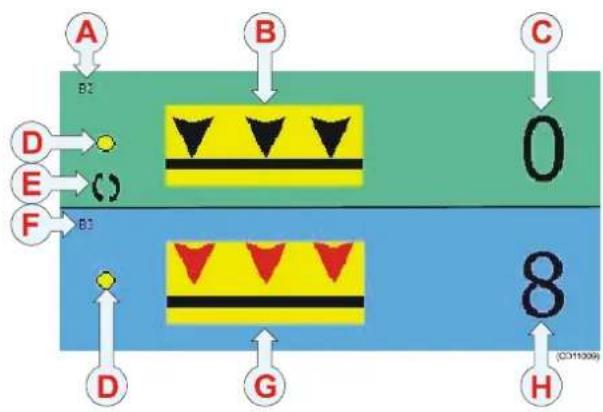
flowchart
graph TD
    A["A"] --> B["B"]
    B --> C["C"]
    D["D"] --> E["E"]
    E --> F["F"]
    F --> G["G"]
    G --> H["H"]
    style A fill:#f9f,stroke:#333
    style B fill:#ccf,stroke:#333
    style C fill:#cfc,stroke:#333
    style D fill:#fcc,stroke:#333
    style E fill:#cff,stroke:#333
    style F fill:#ffc,stroke:#333
    style G fill:#cfc,stroke:#333
    style H fill:#fcc,stroke:#333
(A)=Sensorsetupassensorno.2.
(B)=Sensorincontactwithbottom.
Thetimerhasstopped.
(C)=Thetimercountshowmany
minutesthesensorhasbeen "lifted off" thebottom.Itmustbereset manually.
(D)=Indicator, litforeverysensor interrogation.
(E)=Interferencesymbol.
(F)=Sensorsetupassensorno.3.
(G)=Sensorhaslostcontactwith bottom. Thetimerstarts.Anaudible alarmmaybeenabled.
(H)=Thetimershowshowmany minutesthenethas "liftedoff" duringatow.
Sensorconfiguration
Ondelivery, allBottomContactsensors are configured in Channel 6 and with Normal update rate.
Note: ThesensorandthePI44systemsetupmustcorrespond, otherwisethecommunicationwillnotwork.
Tochangethesensorsetup(channelselection,updaterateetc), usethePIConfiguratorutility.
Thesensorupdateratecontrolshowoftenthesensormonitors whetherthegearisonofoffthebottom.Threesettingsare available.Notethatafasterupdateratewilldecreasethebattery life.
- Fast(\~3,2sec):Recommendedfornewtrawlorgear,or changesinriggingtomonitorinstabilitiesingroundgear bottomcontact.
• Normal(\~5,3sec):Recommendedfornormalfishing.
- Slow(\~33sec):Recommendedifmaximumoperational batterylifebeforechargingisrequired. Thesystemwillbe moresensitivetobadcommunicationconditionsduetothe slowdataupdate.
System configuration
Sensorconfiguration: Thesensormustbeconfiguredwitha uniquesensornumber.Selectupdaterateandchannelnumber accordingtothesensor's configuration.Writedownthis configurationforfuturereference.
Status&Receiver:TheInterferencefiltermustbeswitchedon. Setittolevel9ifyouhavenoiseproblemsfromother hydroacousticsources.Notethatwiththefilteron,itwill influencethesignalspectrumshownintheStatusdisplay.
Catch/Bottomsensorfilter: Switchthisfilteroff.Setitto Light or Heavy only if you experience excessive noise.

Mounting
Location: Placethesensorwhereyou wishtomonitorbottomcontact. This isnormallyinthecenterofthenet. Seizetheattachmentring(A)forthe stayunderneaththenet, thenputtwo carabinehooksinsidethefootrope formingabridleof15to20cm securelyholdingthesensorinastable position.
Penetrationring: Placethe penetrationring(B) forthedetection wire approximately 30cm rear of the footrope. Before final seizing, mount the sensor to the carabine hooks and check that the detection wire(E) passestrough the center of the penetration ring(B). Remove anynet on the inside of the penetration ring.
Setup: Correct function requires that the length of the stay (F) and the detection chain (G) are trimmed with regard to each other and the gearin use. Standard delivery includes a 63 cm stay and 39 cm detection chain for use with 14 to 16 inch bobbinsorrockhoppers (C).

(A)=Attachmentstringforthe
stayseizedsecurelyunderneath
thefootrope
(B)=Penetrationringforthe detectionwire
(C)=Rockhopper,bobbinsetc.
(D)=Endlink
(E)=Detectionwire
(F)=Stay
(G)=Detectionchain
(H)=Weight\~5.5kg
(J)=Weightandstayhang freely.
(K)=Bottom
(L)=Angleapproximately25°
Adjustment: Laythesensoronanelevated surface. Adjust the length of the detection chain (G) as necessary. Observed detection wire (E) movement whilesimulating bottom contact by raising the weight. Tilt the weight approximately 25° to compensate for drag forces when towed through the water, and adjust the stay length to beaut. To avoid damage, removal the weight before coiling the gear on the drum.
Note: Thesensor'sdetectionwiremustalwaysbeallowedtopass freelythroughthecenterofthepenetrationringwhenitis deployed.Attachtherubberstrapssothatthesensorisheld horizontallyduringtowing.
Sacrificialwaterswitchsensor
Ifthewaterswitchonyoursensorisasacrificialbrassscrew, thisscrewmustbecheckedeverymonth. Wheneverrequired duetowearandtear,thescrewmustbereplaced.Refertothe Operationalproceduresintheoperatormanual.
PS Bottom Contact sensor
Purpose
The PS Bottom Contact sensor detects if a trawl is accidentally liftedofftheseabed,orapurseseineistouchingthebottom.

natural_image
Illustration of a fishing net with a gold object and a rope, surrounded by fish (no text or symbols)
(A)=Thetrawlfollowsthebottom. Thedetectionwireonthesensorisnotreleased.
(B)=Thetrawlhasliftedoffthebottom,andthedetectionwireisreleased.


Mainparts
(A)=Negativecharging/fasteninglug
(B)=Positivecharging/fasteninglug
(C)=Communicationlink(Channel1-30)
(D)=Locationofsensorlamp
(E)=Waterswitchsensor
(F)=Detectionwire(in/out)
(G)=Groundweight
Dailyoperation
Onceinstalledandputtouse,thesensorwill automaticallybeswitchedononcethe waterswitchisactivated.Afteraninitialstartup, thesensorstartstransmissionofthedetectorwire (F)status(inorout).Whenthesensorisnotin use,checkthatthesensorlamp(D)isnotflashing fromtimetotime,asthisindicatiesthatthe sensorisonandisdischargingitsbatteries.In thiscase,wasthesensorinfreshwatertoremove saltanddirt.
If you operate with Fastupdaterate, the sensor must be charged approximately every 35 hours. Used with Normal or Slow update rates, the operational life is approximately 60 or 250 hours respectively. The optimal sensor charging temperature is from +10 to +25°C.
Note: Notethatchargingsensorsatsub-zerotemperaturescancreate explosivegasses.SimradASassumesnoliabilityforthe improperchargingofsensorsortheuseofchargersnot specifiedinSimradsensorchargingdocumentation.
Bottom Contactpresentation
OnthePI44display,theBottomContactsensorstatusis displayedwithgraphicsymbols.Notethatthetimerscountthe totalnumberofminutesthesensorhaslostcontactwithbottom. Ifonlypredictedtimervaluesexist,thecharactersareshowning grey.Ifthesensorcommunicationislost,thegraphicsymbolis replacedbythecharacters***.*(ingrey).

flowchart
graph TD
    A["A"] --> B["B"]
    B --> C["C"]
    D["D"] --> E["E"]
    E --> F["F"]
    F --> G["G"]
    G --> H["H"]
    style A fill:#fff,stroke:#000
    style B fill:#fff,stroke:#000
    style C fill:#fff,stroke:#000
    style D fill:#fff,stroke:#000
    style E fill:#fff,stroke:#000
    style F fill:#fff,stroke:#000
    style G fill:#fff,stroke:#000
    style H fill:#fff,stroke:#000
(A)=Sensorsetupassensorno.2.
(B)=Sensorincontactwithbottom.
Thetimerhasstopped.
(C)=Thetimercountshowmany minutesthesensorhasbeen "lifted off" thebottom. It must be reset manually.
(D)=Indicator, litforeverysensor interrogation.
(E)=Interferencesymbol.
(F)=Sensorsetupassensorno.3.
(G)=Sensorhaslostcontactwith bottom. Thetimerstarts.Anaudible alarmmaybeenabled.
(H)=Thetimershowshowmany minutesthenethas "liftedoff" duringatow.
Sensorconfiguration
Ondelivery, allBottomContactsensors are configured in Channel 6 and with Normal update rate.
Note: ThesensorandthePI44systemsetupmustcorrespond, otherwisethecommunicationwillnotwork.
Tochangethesensorsetup(channelselection,updaterateetc), usethePIConfiguratorutility.
Thesensorupdateratecontrolshowoftenthesensormonitors whether the gearisonofoffthebottom. Threesettings are available. Notethatafasterupdaterate will decrease the battery life.
Fast(\~3,2sec):Recommendedfornewtrawlorgear,or changesinriggingtomonitorinstabilitiesingroundgearbottom contact.
Normal(\~5,3sec):Recommendedfornormalfishing.
Slow(\~33sec):Recommendedifmaximumoperationalbattery lifebeforechargingisrequired. Thesystemwillbemore sensitivetobadcommunicationconditionsduetotheslowdata update.
System configuration
Sensorconfiguration: Thesensormustbeconfiguredwitha uniquesensornumber.Selectupdaterateandchannelnumber accordingtothesensor'sconfiguration.Writedownthis configurationforfuturereference.
Status&Receiver:TheInterferencefiltermustbeswitchedon. Setittolevel9ifyouhavenoiseproblemsfromother hydroacousticsources.Notethatwiththefilteron,itwill influencethesignalspectrumshownintheStatusdisplay.
Catch/Bottomsensorfilter:Switchthisfilteroff.Setitto Light or Heavy only if you experience excessive noise.

Mounting
Location: Placethesensorwhereyou wishtomonitorbottomcontact. This isnormallyinthecenterofthenet. Seizetheattachmentring(A)forthe stayunderneaththenet, thenputtwo carabinehooksinsidethefootrope formingabridleof15to20cm securelyholdingthesensorinastable position.
Penetrationring: Placethe penetrationring(B) forthedetection wire approximately 30cm rear of the footrope. Before final seizing, mount the sensortothecarabine hooks and check that the detection wire(E) passestrough the center of the penetration ring(B). Remove anynet on the inside of the penetration ring.
Setup: Correct function requires that the length of the stay (F) and the detection chain (G) are trimmed with regard to each other and the gearin use. Standard delivery includes a 63 cm stay and 39 cm detection chain for use with 14 to 16 inch bobbinsorrockhoppers (C).

(A)=Attachmentringforthe
stayseizedsecurelyunderneath
thefootrope
(B)=Penetrationringforthe detectionwire
(C)=Rockhopper,bobbinsetc.
(D)=Endlink
(E)=Detectionwire
(F)=Stay
(G)=Detectionchain
(H)=Weight\~5.5kg
(J)=Weightandstayhang freely.
(K)=Bottom
(L)=Angleapproximately25°
Adjustment: Laythesensoronanelevated surface. Adjust the length of the detection chain (G) as necessary. Observed detection wire (E) movement whilesimulating bottom contact by raising the weight. Tilt the weight approximately 25° to compensate for drag forces when towed through the water, and adjust the stay length to beaut. To avoid damage, removal the weight before coiling the gear on the drum.
Note: Thesensor'sdetectionwiremustalwaysbeallowedtopass freelythroughthecenterofthepenetrationringwhenitis deployed.Attachtherubberstrapssothatthesensorisheld horizontallyduringtowing.
PI Catch sensor
Purpose
The PI Catch sensor detects when the trawl has been filled with fish. Thesensormonitorstheopeningofthemeshesinthecod end, and will be activated on cethevolumecaughtisenoughto pullthedetectorwires.
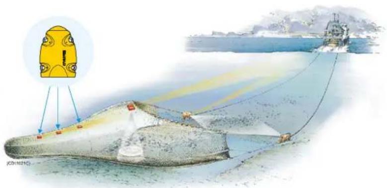
natural_image
Illustration of a submarine being grounded near a ship's deck, with a yellow vehicle component above (no text or symbols)
Catchsensorprinciple:Threesensors are mounted at the codendofthetrawl to detect the amount of fish caught.
Mainparts
(A)=Negativecharging/fasteninglug
(B)=Positivecharging/fasteninglug
(C)=Communicationlink
(D)=Locationofsensorlamp
(E)=Waterswitchsensor
(F)=Detectionwires
Dailyoperation
Tomonitorthefillingrate, were recommend that you use minimum twosensors. The first sensor is located at the forendof the cod-end indicating that the trawl is fishing, while these seconds sensor tells whentohaul. Dueto the fish moving back and forth in the cod-end, the sensor will normally changestatus (on/off) several times until the volumec aught keep the opening of themes hes stable.
Onceinstalledandputtouse,thesensorwillautomaticallybe switchedononcethewaterswitchisactivated.Afteraninitial startup,thesensorstartstransmissionofthedetectionwires(F) status(inorout).Whenthesensorisnotinuse,checkthatthe sensorlamp(D)isnotflashingfromtimetotime,asthis indicatiesthatthesensorisonandisdischargingitsbatteries. Inthiscase,washthesensorinfreshwatertoremovesaltand dirt.
If you operate with Fast update rate, the sensor must be charged approximately every 35 hours. Used with Normal or Slow updaterates, the operationallifeisapproximately150or300 hoursrespectively. Theoptimalsensorchargingtemperatureis from+10to+25°C.
Note: Notethatchargingsensorsatsub-zerotemperaturescancreate explosivegasses.SimradASassumesnoliabilityforthe improperchargingofsensorsortheuseofchargersnot specifiedinSimradsensorchargingdocumentation.
Presentation
OnthePI44display,theCatchsensorstatusisdisplayedwith graphicsymbols.Thetimerscountthetotalnumberofminutes thesensorhasbeenactivated(redrectangle).Ifonlypredicted timervaluesexist,thetimercharactersareshowningrey.Ifthe sensorcommunicationislost,thegraphicsymbolisreplacedby thecharacters***.*(ingrey).
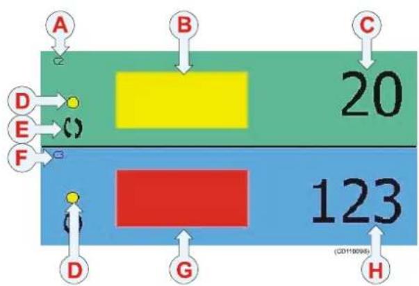
flowchart
graph TD
    A["A"] --> C["2"]
    B["B"] --> C["2"]
    C --> D["D"]
    D --> E["E"]
    E --> F["F"]
    F --> G["G"]
    G --> H["H"]
    C --> I["20"]
    I --> J["123"]
    style I fill:#f9f,stroke:#333
    style J fill:#bbf,stroke:#333
(A)=Sensorsetupassensorno.2.
(B)=Sensorinstandby. Thetimer hasstopped.
(C)=Thetimercountshowmany
minutesthesensorhasbeenactivated
duringatow.Itmustbereset
manually.
(D)=Indicator, litforeverysensor interrogation.
(E)=Interferencesymbol.
(F)=Sensorsetupassensorno.3.
(G)=Thesensorhasbeenactivated. Thetimerstarts. An audiblealarmmaybeenabled.
(H)=Thetimershowshowmanyminutesthesensorhasbeen activated.
Sensorconfiguration
Ondelivery, allCatchsensors are configured in Channel4 and with Normal update rate. If you use more than one Catch sensor, makes sure that you set them up to operate on different channels and with different sensor numbers!
Note: ThesensorandthePI44systemsetupmustcorrespond, otherwisethecommunicationwillnotwork.
Tochangethesensorsetup(channelselection,updaterateetc), usethePIConfiguratorutility.
TheCatchsensorcanbeconfigured(usingthePIConfigurator software)toactasaFA701catchsensor.Thiswillallowthe sensortobeusedwiththeSimradFStrawlsonar.The communicationchannelontheFSsonarmustbesetupto correspondtotheequivalentsensornumber(1,23or4).
Thesensorupdateratecontrolshowoftentheamountoffish caughtismeasuredandtransmittedtothevessel.Threesettings areavailable.Notethatafasterupdateratewilldecreasethe batterylife.
- Fast(\~5,3sec):Recommendedfortrawlinginareaswhere therateoffillingisveryhigh. Usethissettingtoavoid damagetothetrawlorexcessivecatches.
• Normal(\~33sec):Recommendedfornormalfishing. - Slow(\~125sec):Recommendedifmaximumoperational batterylifebeforechargingisrequired.Thesystemwillbemoresensitivetobadcommunicationconditionsduetotheslowdataupdate.
When the Catch sensor is configured as an FA701, it will have a constantupdaterateofapproximately80seconds. This rate mustnotbechanged.
System configuration
Sensorconfiguration: Thesensormustbeconfiguredwitha uniquesensornumber.Selectupdaterateandchannelnumber accordingtothesensor's configuration.Writedownthis configurationforfuturereference.
Status&Receiver:TheInterferencefiltermustbeswitchedon. Setittolevel9ifyouhavenoiseproblemsfromother hydroacousticsources.Notethatwiththefilteron,itwill influencethesignalspectrumshownintheStatusdisplay.
Catch/Bottomsensorfilter: Switch this filter off. Set to Light or Heavy only if you experience excessive noise.
Mounting
Location: Attachthesensorontopofthecod-endwherethe catchistobemonitored. Asthecod-endfills, thenet'smeshes willopenpullingthedetectorwiresandthusactivating the sensor.

flowchart
graph TD
    A["Yellow Component"] --> B["A"]
    A --> C["C"]
    A --> D["D"]
    A --> E["E"]
    A --> F["F"]
    B --> B1["B"]
    C --> C1["C"]
    D --> D1["D"]
    E --> E1["E"]
    F --> F1["F"]
    style A fill:#FFD700,stroke:#333
    style B fill:#FFA500,stroke:#333
    style C fill:#FFA500,stroke:#333
    style D fill:#FFA500,stroke:#333
    style E fill:#FFA500,stroke:#333
    style F fill:#FFA500,stroke:#333
Sensorattachmenttoanetwithanapproximatemeshsizeof140mm. Thedistance between the anchor points for the attachment rings and rubber straps will vary according to mesh size and sensitivity required.
(A)=Snaphookandscrewlink
(B)=Steelattachmentringsbenttothenet
(C)=Nylonattachmentringsbenttothenet
(D)=Detectionwires
(E)=Rubberstrap
(F)=Attachmentpoint
Attachment: The Catchsensor's orientation toward the vessel is maintained by the steel and nylon attachment rings. The number of meshest attachment rings are supported between must be restricted to avoid unnecessary stress on the sensors fastening lugs when the cod-end is filled to maximum. The use of both nylon and steel attachment rings is required to secure the sensor lugs if excessive forces are applied on them. Then nylon rings will stretch or breakdown, but the steel ring will prevent the sensor from being lost. Not that two steel rings must be mounted on these same side.
Sensitivity: ThesensitivityoftheCatchsensorisdeterminedby thenumberofmeshesseparatingtherubberstraps. Youcan simulatethisbystretchingthenet'smeshestoapproximatethe meshopeningestimatedtotriggerthesensor.Markthelocation (withcoloredthread)forfuturereferences.
Rubberstraps: Inspecttherubberstraps regularly and always before anewhaul. Replacethemifyoudetectvisiblesignsof cracksordamage.
Sacrificialwaterswitchsensor
Ifthewaterswitchonyoursensorisasacrificialbrassscrew, thisscrewmustbecheckedeverymonth. Wheneverrequired duetowearandtear,thescrewmustbereplaced.Refertothe Operationalproceduresintheoperatormanual.
PS Catch sensor
Purpose
The PSCatchsensordetectswhenthetrawlhasbeenfilled withfish. Thesensormonitorstheopeningofthemeshesinthe codend, and will beactivated oncethevolumecaughtisenough topullthedetectorwires.

natural_image
Illustration of a submarine being deployed at sea, with a yellow device and blue cables visible (no text or symbols)
Catchsensorprinciple:Threesensors are mounted at the codendofthetrawltodetectthe amountoffishcaught.
Mainparts
(A)=Negativecharging/fasteninglug
(B)=Positivecharging/fasteninglug
(C)=Communicationlink
(D)=Locationofsensorlamp
(E)=Waterswitchsensor
(F)=Detectionwires

Dailyoperation
Tomonitorthefillingrate, were recommend that you use minimum twosensors. The first sensor is located at the forendof the cod-end indicating that the trawl is fishing, while these seconds sensor tells whentohaul. Dueto the fish moving back and forth in the cod-end, the sensor will normally changestatus (on/off) several times until the volumec aught keepsthe opening of the meshes stable.
Onceinstalledandputtouse,thesensorwillautomaticallybe switchedononcethewaterswitchisactivated.Afteraninitial startup,thesensorstartstransmissionofthedetectorwire(F) status(inorout).Whenthesensorisnotinuse,checkthatthe sensorlamp(D)isnotflashingfromtimetotime,asthis indicatiesthatthesensorisonandisdischargingitsbatteries.In thiscase,washthesensorinfreshwatertoremovesaltanddirt.
If you operate with Fast update rate, the sensor must be charged approximately every 60 hours. Used with Normal or Slow updaterates, the operationalallifeisapproximately250or450 hoursrespectively. WhenthesensorisconfiguredasanFA701, the operationaltimeisapproximately250hours. The optimal sensorchargingtemperatureisfrom+10to+25°C.
Note: Notethatchargingsensorsatsub-zerotemperaturescancreate explosivegasses.SimradASassumesnoliabilityforthe improperchargingofsensorsortheuseofchargersnot specifiedinSimradsensorchargingdocumentation.
Catchpresentation
OnthePI44display,theCatchsensorstatusisdisplayedwith graphicsymbols.Thetimerscountthetotalnumberofminutes thesensorhasbeenactivated(redrectangle).Ifonlypredicted timervaluesexist,thetimercharactersareshowningrey.Ifthe sensorcommunicationislost,thegraphicsymbolisreplacedby thecharacters***.*(ingrey).

flowchart
graph TD
    A["A"] --> B["B"]
    B --> C["C"]
    D["D"] --> E["E"]
    E --> F["F"]
    F --> G["G"]
    G --> H["H"]
    style A fill:#fff,stroke:#000
    style B fill:#ff0000,stroke:#000
    style C fill:#ff0000,stroke:#000
    style D fill:#fff,stroke:#000
    style E fill:#fff,stroke:#000
    style F fill:#fff,stroke:#000
    style G fill:#ff0000,stroke:#000
    style H fill:#fff,stroke:#000
(A)=Sensorsetupassensorno.2.
(B)=Sensorinstandby. Thetimer hasstopped.
(C)=Thetimercountshowmany minutesthesensorhasbeenactivated duringatow.Itmustbereset manually.
(D)=Indicator, litforeverysensor interrogation.
(E)=Interferencesymbol.
(F)=Sensorsetupassensorno.3.
(G)=Thesensorhasbeenactivated. Thetimerstarts.Anaudiblealarm maybeenabled.
(H)=Thetimershowshowmany minutesthesensorhasbeen activated.
Sensorconfiguration
Ondelivery, allCatchsensors are configured in Channel4 and with Normalupdaterate. If you use more than one Catch sensor, makes sure that you set them up to operate on different channels and with different sensor numbers!
Note: ThesensorandthePI44systemsetupmustcorrespond, otherwisethecommunicationwillnotwork.
Tochangethesensorsetup(channelselection,updaterateetc), usethePIConfiguratorutility.
TheCatchsensorcanbeconfigured(usingthePIConfigurator software)toactasaFA701catchsensor.Thiswillallowthe sensortobeusedwiththeSimradFStrawlsonar.The communicationchannelontheFSsonarmustbesetupto correspondtotheequivalentsensornumber(1,2,3or4).
Thesensorupdateratecontrolshowoftentheamountoffish caughtismeasuredandtransmittedtothevessel.Threesettings areavailable.Notethatafasterupdateratewilldecreasethe batterylife.
- Fast(\~5,3sec):Recommendedfortrawlinginareaswhere therateoffillingisveryhigh. Usethissettingtoavoid damagetothetrawlorexcessivecatches.
• Normal(\~33sec):Recommendedfornormalfishing. - Slow(\~125sec):Recommendedifmaximumoperational batterylifebeforechargingisrequired.Thesystemwillbemoresensitivetobadcommunicationconditionsduetotheslowdataupdate.
- When the Catch sensor is configured as an FA701, it will have a constant updaterate of approximately 80 seconds. This ratemust not be changed.
System configuration
Sensorconfiguration: Thesensormustbeconfiguredwitha uniquesensornumber.Selectupdaterateandchannelnumber accordingtothesensor's configuration.Writedownthis configurationforfuturereference.
Status&Receiver:TheInterferencefiltermustbeswitchedon. Setittolevel9ifyouhavenoiseproblemsfromother hydroacousticsources.Notethatwiththefilteron,itwill influencethesignalspectrumshownintheStatusdisplay.
Catch/Bottomsensorfilter: Switch this filter off. Set to Light or Heavy only if you experience excessive noise.
Mounting
Location: Attachthesensorontopofthecod-endwherethe catchistobemonitored. Asthecod-endfills, thenet'smeshes willopenpullingthedetectorwiresactivatingthesensor.

flowchart
graph TD
    A["Yellow Robot"] --> B["A"]
    A --> C["C"]
    A --> D["D"]
    A --> E["E"]
    A --> F["F"]
    style A fill:#ffcccc,stroke:#333
    style B fill:#ffcccc,stroke:#333
    style C fill:#ffcccc,stroke:#333
    style D fill:#ffcccc,stroke:#333
    style E fill:#ffcccc,stroke:#333
    style F fill:#ffcccc,stroke:#333
Sensorattachmenttoanetwithanapproximatemeshsizeof140mm. Thedistance between the anchorpoints for the attachment rings and rubber straps will vary according to mesh size and sensitivity required.
(A)=Carabinehookandscrewlink
(B)=Steelattachmentringsbenttothenet
(C)=Nylonattachmentringsbenttothenet
(D)=Detectionwires
(E)=Rubberstrap
(F)=Attachmentpoint
Attachment: The Catchsensor's orientation towards the vessel is maintained by the steel and nylon attachment rings. The number of meshest attachment rings are supported between must be restricted to avoid unnecessary stress on the sensors fastening lugs when the cod-end is filled to maximum. The use of both nylon and steel attachment rings is required to secure the sensor lugs if excessive forces are applied on them. Then nylon rings will stretch or breakdown, but the steel ring will prevent the sensor from being lost. Not that two steel rings must be mounted on these sideside.
Sensitivity: Thesensitivity of the Catchsensor is determined by thenumberofmeshesseparatingtherubberstraps. You can simulate this by stretching thenet's meshestoapproximate the meshopening estimated to trigger the sensor. Markthelocation (with colored thread) for further references.
Rubberstraps: Inspecttherubberstraps regularly and always before anewhaul. Replacethemifyoudetectvisiblesignsof cracksordamage.
PI Depth sensor
Purpose
The PIDepthsensormonitorsthecurrentdepthofthenet, as wellastherateofanydepthchanges. All measurements are relatedtothesurface.

(A)=TwoDepthsensorsaremountedtothegroundropeto monitorthedepth.
(B)=OneBottomContactsensorismountedtothegroundrope todetectifthenethitsthebottom.

Mainparts
(A)=Negativecharging/fasteninglug
(B)=Positivecharging/fasteninglug
(C)=Communicationlink
(D)=Locationofsensorlamp
(E)=Waterswitchsensor
(F)=Pressuresensor(labelisremoved)
Dailyoperation
Onceinstalledandputtouse,thesensorwill automaticallybeswitchedononcethe waterswitchisactivated.Afteraninitialstartup, thesensorstartstransmissionofthecurrentdepth whenthisexceedsapredefineddepthyouhave selected.Whenthesensorisnotinuse,checkthat thesensorlamp(D)isnotflashingfromtimeto time,asthisindicatesthatthesensorisonandis dischargingitsbatteries.Inthiscase,washthe sensorinfreshwatertoremovesaltanddirt.
If you operate with Fastupdaterate, the sensormustbecharged approximately every 24 hours. Used with Normal or Slow updaterates, the operationallifeis approximately 75 or 150 hours respectively. The optimal sensorcharging temperature is from +10 to +25°C.
Note: Notethatchargingsensorsatsub-zerotemperaturescancreate explosivegasses.SimradASassumesnoliabilityforthe improperchargingofsensorsortheuseofchargersnot specifiedinSimrad'ssensorchargingdocumentation.
Numericalpresentation
OnthePI44display, thedepthisdisplayedinthenumeric display. Thedescendingorascendingrateisshowninunitsper minutesupported by an arrow indicating the direction. In order to monitor changes of depth as a function of time, the depth will also be displayed in the graphic display showing both the numeric value and corresponding marker line for each sensor. Whenthereadings are stable, the digits are shown in black colour. Whenthe values are predicted, the digits are grey, and if the contact is lost, the characters*. **areshowning grey.

bar
| Category | Value | |---|---| | E | 105 | | D | 99.5 | | F | 8 | | G | ( ) |(A)=Sensorsetupassensorno.1.
(B)=Currentdepth.
(C)=Currentrateofdepthchange. Thearrowindicates that the depth this ascending.
(D)=Indicator, litforeverysensor interrogation.
(E)=Graphicalarm
(F)=Sensorsetupassensorno.2.
(G)=Interferencesymbol.
(H)=Currentrateofdepthchange. Thearrowindicates that the depth this descending.
Sensorconfiguration
Ondelivery, alldepthsensors are configured in Channel16 (300 m), Channel 12 (600 m) or Channel 10 (1000 m) and with Fastupdaterate. If you use more than one sensor, you must set them up to operate indifferent channels.
Note: ThesensorandthePI44systemsetupmustcorrespond, otherwisethecommunicationwillnotwork.
Tochangethesensorsetup(channelselection), use the PI Configurator utility.
Thesensorupdateratecontrolshowoftenthesensorreadsand reportsthecurrentdepth.Threesettingsareavailable.Notethat afasterupdateratewilldecreasethebatterylife.
- Fast(\~4,5sec):Recommendedforpurseeseineortrawl, allows immediate update of critical depth information, and help to avoid damage to the purseeseineortrawl.
- Normal(\~14sec):Recommendedfortrawlandnormal fishing.
- Slow(\~34sec):Recommendedifmaximumoperational batterylifebeforechargingisrequired.Thesystemwillbe moresensitivetobadcommunicationconditionsduetothe slowdataupdate.
System configuration
Sensorconfiguration: Thesensormustbeconfiguredwitha uniquesensornumber.Selectchannelnumberaccordingtothe sensor's configuration.Writedowntheconfigurationforfuture reference.
Status&Receiver:TheInterferencefiltermustbeswitchedon. Setittolevel9ifyouhavenoiseproblemsfromother hydroacousticsources.Notethatwiththefilteron,itwill influencethesignalspectrumshownintheStatusdisplay.
Sensor filter: Switch this filter to Light. Set it to Heavy only if you experience excessivenoise.PositionOffwillprovideraw data and fastest possibleresponse.
Mounting
Purseseine: Inordertosecurestablecommunicationwiththe vessel'shydrophone, it is very important that the sensoris allowed to hang freely with the endpoint pointing towards the surfaced uringshooting and pursuing.

Attachthesensortoastandardpurse ringwithtwoseparatewires(A). Mountoneendofeachwiretoa commonsnaphook(B),andplace anothersnaphookattheotherendof eachwiretosnapontothesensor.
Mountasafetyline(C)between the sensorandtheadjacentbridle/purse ring. Makesurethatsecuritylinedoes notpreventthesensorfromhanging freely!
Removethesensorfromthepurse seinebeforeitpassesthroughthe powerblock.
Anyattachmentmaterial "permanently"attachedtothe sensor'scharginglugsmustnotform anelectricalconnectionbetweenthe twocharginglugsshortingthe chargingcurrent.
(A)=Twowireswithasnaphookin oneendandtheotherendattached permanentlyto(B).
(B)=Largesnaphook.
(C)=Safetywirewithsnaphookson eachend. Notethattheupperendis NOTattachedtothepurseseinewire.

Tunapurse: Thesensormustnotbe attachedtothefootropewire, butto thefoot-ropechain. Useasafetywire inadditionincasethesensorisripped offthenet.

TrawlorDanishseine: The depth sensoris normally attached to the headrope (A). For secure fastening and stable positioning of the sensor pointing toward the vessel, make a finemeshbag (B) located at the centre of the headrope. Sizetwosnap hooks (C) approximately 10-15cm from the headrope forming abridle, and keep the sensor stretched by means soft worubber straps (D) attached to the aft fastening lugs.
Sacrificialwaterswitchsensor
Ifthewaterswitchonyoursensorisasacrificialbrassscrew, thisscrewmustbecheckedeverymonth. Wheneverrequired duetowearandtear,thescrewmustbereplaced. Refertothe Operationalproceduresintheoperatormanual.
PS Depth sensor
Purpose
The PS Depth sensor monitors the current depth of the net, as wellastherateofanydepthchanges. All measurements are related to the surface.

(A)=TwoDepthsensorsaremountedtothegroundropeto monitorthedepth.
(B)=OneBottomContactsensorismountedtothegroundrope todetectifthenethitsthebottom.

Mainparts
(A)=Negativecharging/fasteninglug
(B)=Positivecharging/fasteninglug
(C)=Communicationlink
(D)=Locationofsensorlamp
(E)=Waterswitchsensor
(F)=Pressuresensor(labelisremoved)
Dailyoperation
Onceinstalledandputtouse,thesensorwill automaticallybeswitchedononcethe waterswitchisactivated.Afteraninitialstartup, thesensorstartstransmissionofthecurrentdepth whenthisexceedsapredefineddepthyouhave selected.Whenthesensorisnotinuse,checkthat thesensorlamp(D)isnotflashingfromtimeto time,asthisindicatesthatthesensorisonandis dischargingitsbatteries.Inthiscase,washthe sensorinfreshwatertoremovesaltanddirt.
YoucanonlyoperatethissensorwithFastupdaterate,the sensormustthenbechargedapproximatelyevery35hours.The optimalsensorchargingtemperatureisfrom+10to+25°C.
Note: Notethatchargingsensorsatsub-zerotemperaturescancreate explosivegasses.SimradASassumesnoliabilityforthe improperchargingofsensorsortheuseofchargersnot specifiedinSimrad'ssensorchargingdocumentation.
Numericalpresentation
OnthePI44display, thedepthisdisplayedinthenumeric display. Thedescendingorascendingrateisshowninunitsper minutesupported by an arrow indicating the direction. In order to monitor changes of depth as a function of time, the depth will also be displayed in the graphic display showing both the numeric value and corresponding marker line for each sensor. Whenthereadings are stable, the digits are shown in black colour. Whenthe values are predicted, the digits are grey, and if the contact is lost, the characters*. **areshowning grey.

bar
| Label | Value | |---|---| | A | 105 | | B | 3 | | C | 8 | | D | 99.5 | | E | [n] | | F | [n] | | G | () | (CD1103K)(A)=Sensorsetupassensorno.1.
(B)=Currentdepth.
(C)=Currentrateofdepthchange. Thearrowindicates that the depth this ascending.
(D)=Indicator, litforeverysensor interrogation.
(E)=Graphicalarm
(F)=Sensorsetupassensorno.2.
(G)=Interferencesymbol.
(H)=Currentrateofdepthchange. Thearrowindicatesthatthedepthis descending.
Sensorconfiguration
Ondelivery, alldepthsensors are configured in Channel16 (300 m), Channel 12 (600 m) or Channel 10 (1000 m) and with Fastupdaterate. It is not possible to change the updaterate setting. If you use more than one sensor, you must set them up to operate indifferent channels.
Note: ThesensorandthePI44systemsetupmustcorrespond, otherwisethecommunicationwillnotwork.
Tochangethesensorsetup(channelselection), usethe PI Configuratorutility.
Thesensorupdateratecontrolshowoftenthedepthis measured, and the datatransmitted to the vessel. Tobeableto monitor critical depth information and avoid damage to the pursese in the trawl, the depths sensor will only operate on Fastupdaterate.
System configuration
Sensorconfiguration: Thesensormustbeconfiguredwitha uniquesensornumber.Selectchannelnumberaccordingtothe sensor's configuration.Writedowntheconfigurationforfuture reference.
Status&Receiver:TheInterferencefiltermustbeswitchedon. Setittolevel9ifyouhavenoiseproblemsfromother hydroacousticsources.Notethatwiththefilteron,itwill influencethesignalspectrumshownintheStatusdisplay.
Sensor filter: Switch this filter to Light. Set it to Heavy only if you experience excessivenoise.PositionOffwillprovideraw data and fastest possibleresponse.
Mounting
Purseseine: Inordertosecurestablecommunicationwiththe vessel'shydrophone, it is very important that the sensoris allowed to hang freely with the endpoint pointing towards the surfaced uringshooting and pursuing.

Attachthesensortoastandardpurse ringwithtwoseparatewires(A). Mountoneendofeachwiretoa commonsnaphook(B),andplace anothersnaphookattheotherendof eachwiretosnapontothesensor.
Mountasafetyline(C)between the sensorandtheadjacentbridle/purse ring. Makesurethatsecuritylinedoes notpreventthesensorfromhanging freely!
Removethesensorfromthepurse seinebeforeitpassesthroughthe powerblock.
Anyattachmentmaterial "permanently"attachedtothe sensor'scharginglugsmustnotform anelectricalconnectionbetweenthe twocharginglugsshortingthe chargingcurrent.
(A)=Twowireswithasnaphookin oneendandtheotherendattached permanentlyto(B).
(B)=Largesnaphook.
(C)=Safetywirewithsnaphookson eachend. Notethattheupperendis NOTattachedtothepurseseinewire.

Tunapurse: Thesensormustnotbe attachedtothefootropewire, butto thefoot-ropechain. Useasafetywire inadditionincasethesensorisripped offthenet.

TrawlorDanishseine: The depth sensoris normally attached to the headrope (A). For secure fastening and stable positioning of the sensor pointing toward the vessel, make a finemeshbag (B) located at the centre of the headrope. Sizetwosnap hooks (C) approximately 10-15 cm from the headrope forming abridle, and keep the sensor stretched by means soft worubber straps (D) attached to the aft fastening glugs.
PI Height sensor
Purpose
The PI Height sensor monitors the current height of the trawl, as well as therate of any height changes. All measurements are related to the bottom.


(A)=ThePIHeightsensorisnormally mountedontheheadrope, andbymeansof thebuilt-inechosounderitwillmeasurethe distancetothebottom.
(B)=Echosoundertransmissionfield
Mainparts
(A)=Negativechargingandfasteninglug
(B)=Positivechargingandfasteninglug
(C)=Communicationlink
(D)=Locationofsensorlamp
(E)=Waterswitchsensor
(F)=Echosoundertransducer-mustbe directedtowardstheseabed!
Dailyoperation
Onceinstalledandputtouse,theHeightsensorwill automaticallybeswitchedononcethewaterswitchisactivated. Afteraninitialstartup,thesensorstartstheechosounder,and thedepthresultsaretransmittedtothevessel.Whenthesensors arenotinuse,checkthatthesensorlamp(D)donotflashfrom timetotime,asthisindicatesthatthesensorisonandis dischargingitsbatteries.Inthiscase,washthesensorinfresh watertoremovesaltanddirt.
If you operate with Fastupdaterate, the sensors must be charged approximately every 35 hours. Used with Normalor Slowupdaterates, the operational life is approximately 60 or 250 hours respectively. The optimal sensor charging temperature is from +10 to +25°C. Thesensor can only be charged with the PIC charger.
Note: Chargingsensorsatsub-zerotemperaturescancreateexplosive gasses.SimradASassumesnoliabilityfortheimproper chargingofsensorsortheuseofchargersnotspecifiedin Simrad'ssensorchargingdocumentation.
Numericalpresentation
OnthePI44display,thedistancetothebottomisdisplayedin thenumericdisplay.Iftheheightisincreasingordecreasing, thisisshownwithtwoarrowsandthevariationinmetersper second.Whenthereadingsarestable,thedigitsareshownin blackcolour.Whenthevaluesarepredicted,thedigitsaregrey, andifthecontactislost,thecharacters*.* *areshowningrey.

flowchart
graph TD
    A["A"] --> H1["H1"]
    B["B"] --> H1
    C["C"] --> H1
    D["D"] --> H1
    E["E"] --> H1
    F["F"] --> H1
    G["G"] --> H1
    H1 --> H2["△"]
    H2 --> H3["●"]
    H3 --> H4["☐"]
    H4 --> H5["☐"]
    H5 --> H6["☐"]
    H6 --> H7["☐"]
    H7 --> H8["☐"]
    H8 --> H9["☐"]
    H9 --> H10["☐"]
    H10 --> H11["☐"]
    H11 --> H12["☐"]
    H12 --> H13["☐"]
    H13 --> H14["☐"]
    H14 --> H15["☐"]
    H15 --> H16["☐"]
    H16 --> H17["☐"]
    H17 --> H18["☐"]
    H18 --> H19["☐"]
    H19 --> H20["☐"]
(A)=Sensorsetupassensorno.1.
(B)=Heightmeasuredinmeters.
(C)=Currentdistancefromthe sensortothebottom.
(D)=Thedistanceisdecreasingby1 meterspersecond.
(E)=Arrowspointing "out" meansthattheheightis increasing.Arrowspointing "in" meansthattheheightis decreasing.
(F)=Graphicalarm
(G)=Indicator,litforeverysensorinterrogation.
(H)=Interferencesymbol.
Sensorconfiguration
Ondelivery, allHeightsensorsareconfiguredinChannel14 andwithFastupdaterate.
Note: ThesensorandthePI44systemsetupmustcorrespond, otherwisethecommunicationwillnotwork.
Tochangethesensorsetup(channelselection), use the PI Configurator utility.
Thesensorupdateratecontrolshowoftenthesensorreadsand reportstheheight.Threesettingsareavailable.Notethatafaster updateratewilldecreasethebatterylife.
- Fast(\~5,5sec):Recommendedfornewtrawlorchangesin riggingtomonitoranyinstabilitiesorunexpectedchanges. Thismodeprovidestheshortestbatterylifebeforecharging.
- Normal(\~14sec):Recommendedforwellknowntrawl behaviorwithstablesituations. Usethissettingduring normalconditions.
- Slow (\~34 sec): Recommended to monitoring a stable situationovertime. Thesystemwillbemoresensitivetobad communicationconditionsduetotheslowdataupdate. This modeprovideslongestoperationalbatterylifebefore charging.
System configuration
Sensorconfiguration: Thesensormustbeconfiguredwitha uniquesensornumber.Selectchannelnumberandupdaterate accordingtothesensor's configuration.Writedownthe configurationforfuturereference.
Status & Receiver: The Interference filter must be switched on. Setittolevel9ifyouhavenoiseproblemsfromother hydroacousticsources.Notethatwiththefilteron,itwill influencethesignalspectrumshownintheStatusdisplay.
Sensor filter: Switch this filter to Light. Set it to Heavy only if you experience excessive noise. Position Off will provide raw data and fastest possibleresponse.
Mounting
Location: Placethesensorwhereyouwishtomonitorthe height. Thisisnormallyaftoftheheadropeathecenterofthe net.
Ensure that you mount the sensor with there reverseside (D) and the echosounder transducer (E) pointing toward the bottom! The SIMRAD print on the sensor (C) must point uptoward the watersurface!

Mounting: Securethetwoforward fasteninglugs(A)usingtwosnap hooksandrope. Then, securethetwo aftfasteninglugs(B)usingsnap hooksandstrongrubberbands. This mountingplacesthesensorinacradle supportedonallfoursides.
Inordertosecurethesensorinplace, werecommendthatyouassemblea bagoffine-meshednet,andtiesthis tothetrawlclosetothemiddleofthe headrope.Then,mountthesensor insidethisbag.Thesensormustbe properlysecuredtopreventitfrom movingsidewaysorrotateduringuse.
(A)=Ropeandsnaphooks
(B)=Rubberbandsandsnaphooks
(C)=SIMRADimprintonthesensor mustpointup!
(D)=Reversesideofsensor
(E)=Echosoundertransducermust pointtowardsthebottom!
Sacrificialwaterswitchsensor
Ifthewaterswitchonyoursensorisasacrificialbrassscrew, thisscrewmustbecheckedeverymonth. Wheneverrequired duetowearandtear,thescrewmustbereplaced.Refertothe Operationalproceduresintheoperatormanual.
PI Rip sensor
Purpose
The PI Rip sensor is identical to the PI Catch, and it must be regarded as a second application for the Catch sensor. The PI Ripsensor will monitor if your net is damaged and dropped apart due to obstructions or foreign objects on these seabed.


(A)=ThePIRipismountedonthefootropewith thetwosensorwiresstretchedoutandthewires engaged.
(B)=Twostrongrubberbandsensurethatthe sensorisactivated. If thenetistorn, theslackin thenetwilldisengagetheRipsensor.
Mainparts
(A)=Negativechargingandfasteninglug
(B)=Positivechargingandfasteninglug
(C)=Communicationlinktothevessel
(D)=Locationofsensorlamp
(E)=Waterswitchsensor
(F)=Detectionwires
Dailyoperation
Inmostcases, oneortwoRipsensorsmounted onthefootropewillbesufficienttomonitorthe conditionofthenet.
Once installed and puttouse, the sensor will automatically be switched on on the waters switch is activated. After an initial startup, the sensor will detect the status of the detection wires, and transmit this information to the vessel. When the sensor is not in use, check that the sensor lamps (D) donot flash from timetotime, asthis indicate that the sensor is on and discharging its batteries. In this case, wash the sensor in fresh watertore moves salt and dirt.
If you operate with Fastupdaterate, the sensors must be charged approximately every 35 hours. Used with Normalor Slowupdaterates, the operational life is approximately 150 or 300 hours respectively. The optimal sensor charging temperature is from +10 to +25°C.
Note: Notethatchargingsensorsatsub-zerotemperaturescancreate explosivegasses.SimradASassumesnoliabilityforthe improperchargingofsensorsortheuseofchargersnot specifiedinSimrad'ssensorchargingdocumentation.
Numericpresentation
OnthePI44display,theRipsensorstatusisdisplayedwith graphicsymbols.Thetimerscountthetotalnumberofminutes thesensorhasbeenactivated(redrectangle).Ifonlypredicted timervaluesexist,thetimercharactersareshowningrey.Ifthe sensorcommunicationislost,thegraphicsymbolisreplacedby thecharacters***.*(ingrey).
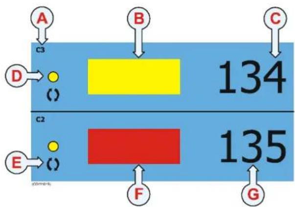
(A)=Sensorsetupassensorno.3.
(B)=Ayellowrectangleindicates that the sensor has deactivated, and that the has been damaged. The timer has stopped.
(C)=Thetimercountshowmany minutesthesensorhasbeenactivated withaserviceablenetduringatow.It mustberesetmanually.
(D)=Indicator, litforeverysensor interrogation.
(E)=Interferencesymbol.
(F)=Aredrectangleindicatesthatthesensorisactivated. This isthenormalposition, anditmeansthatthenetisserviceable. Thetimerisrunning.
(G)=Timer
Sensorconfiguration
Ondelivery, allRipsensorsareconfiguredinChannel4and withNormalupdaterate. If you wishtouse Rip and Catch sensorssimultaneously, one of them must be set to different communication channel.
Note: ThesensorandthePI44systemsetupmustcorrespond, otherwisethecommunicationwillnotwork.
Tochangethesensorsetup(channelselection), usethe PI Configuratorutility.
Thesensorupdateratecontrolshowoftenthesensorreadsand reportstheconditionofthenet.Threesettingsareavailable. Notethatafasterupdateratewilldecreasethebatterylife.
- Fast(\~5,3sec):Recommendedifyoususpectthatthebottom conditionsareroughandunpredicable,andthatdamagemay beeasilyinflicted.Thismodeprovidestheshortestbattery lifebeforecharging.
- Normal(\~33sec):Recommendedfornormalbottom conditions.
- Slow(\~125sec):Recommendedifthebottomconditionsare wellknown, and you know that no obstruction sexist. This mode provides longest operational battery life before charging.
System configuration
Sensorconfiguration: Thesensormustbeconfiguredwitha uniquesensornumber.Selectchannelnumberandupdaterate accordingtothesensor's configuration.Writedownthe configurationforfuturereference.
Status&Receiver:TheInterferencefiltermustbeswitchedon. Setittolevel9ifyouhavenoiseproblemsfromother hydroacousticsources.Notethatwiththefilteron,itwill influencechesignalspectrumshownintheStatusdisplay.
Sensor filter: Switch this filter to Light. Set it to Heavy only if you experience excessive noise. Position Off will provide raw data and fastest possibleresponse.
Mounting
Location: Placethesensorwhereyouwishtocheckthenet condition. Thisisnormallyclosetothefootropeatthecenterof thenet. If thenetistorn, theslack will release one or both of the sensor's detection wires.
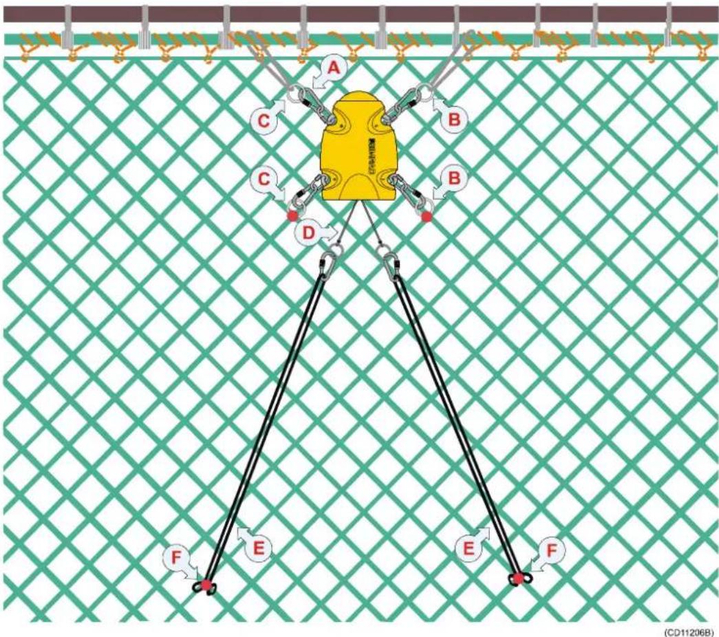
Ripsensorattachmenttothenet, locationjustaftofthefootrope. Thedistancebetween theanchorpointsfortheattachmentringsandrubberstrapsmustbedefineddepending onthesizeofthenetandhowlargeareayouwishtomonitor.
(A)=Snaphookandscrewlink
(B)=Steelattachmentringsbenttothenet
(C)=Nylonattachmentringsbenttothenet
(D)=Detectionwires
(E)=Rubberstrap
(F)=Attachmentpoint
Attachment: Thesensor's orientation toward the vessel is maintained by the steel and nylon attachment rings. Then number of meshest attachment rings are supported between must be restricted to avoid unnecessary stress on the sensors fastening lugs. The use of both nylon and steel attachment rings is required to secure the sensor lugs if excessive forces are applied on them. Then nylon rings will stretch or breakdown, but the steel ring will prevent the sensor from being lost. Not that two steel rings must be mounted on the same side of the sensor.
Rubberstraps: Thetworubberbands(E) must best stretched towards aft, and mounted tothemeshesinsuchaway that the detection wires are engaged during normal operations. The angle between the worubber band should be approximately 70 degrees. Inspecttherubber straps regularly and always before a newhaul. Replacethemify you detect visible sign so for cracks or damage.
Sacrificialwaterswitchsensor
Ifthewaterswitchonyoursensorisasacrificialbrassscrew, thisscrewmustbecheckedeverymonth. Wheneverrequired duetowearandtear,thescrewmustbereplaced. Refertothe Operationalproceduresintheoperatormanual.
PI Spread and Remote sensors
Purpose
The PI Spread and Remote sensors measure the physical distancebetweenthetrawldoors.
Note: EachSpreadsensorcanbeconfiguredtocommunicatewithone
oftworemotesensors; Remote1 or Remote2. LabeltheSpread sensoraccordingly, andensurethatyouonlyusethesensors in thecorrectpairs.


(S)=ThePISpreadsensorismountedina specialadapterontheporttrawldoor.
(R)=ThePIRemotesensorismountedina specialadapteronthestarboardtrawldoor.
(C)=ThePISpreadsensorcommunicateswith thePIsystemonthevessel.
(F)=Usingthetransversecommunicationlink, thetwosensorsmeasurethephysicaldistance betweenthetrawldoors.
Mainparts
(A)=Negativechargingandfasteninglug
(B)=Positivechargingandfasteninglug
(C)=Communicationlinktothevessel
(D)=Locationofsensorlamp(rearsideofPI Spread)
(E)=Waterswitchsensor
(F)=Transversecommunicationlink
Dailyoperation
Once installed and puttouse, the Spreadsensor will automatically beswitched on on cethewaters switch is activated. After an initial startup, the sensor starts interrogating the Remotesensortomeasurethed distance. There results are transmitted to the vessel. Whenthesensors are not in use, check that the sensor lamps (D) donot flash from timetotime, asthis indicate that the sensor is on and discharging its batteries.
If you operate with Fastupdaterate, the sensors must be charged approximately every 45 hours. Used with Normalor Slow update rates, the operational life is approximately 100 or 150 hours respectively. The optimal sensor charging temperature is from +10 to +25°C.
Note: Thetworubberinsertsprovidedatthebottomofeachsensor adaptermustnotbereplacedwithanyothertypesordesigns.It isessentialthattheseinsertsprovideasecurecradleforthe sensors,buttheymustalsoallowforfreewatercirculationto allowthesensor'swaterswitchtoengage.Also,thedesignof theinsertsallowssandandmudtoflowoutwhenthetrawl doorsarepulledupfromthewater.
Note: Notethatchargingsensorsatsub-zerotemperaturescancreate explosivegasses.SimradASassumesnoliabilityforthe improperchargingofsensorsortheuseofchargersnot specifiedinSimrad'ssensorchargingdocumentation.
Numericalpresentation
OnthePI44display,thedistancebetweenthetrawldoorsis displayedinthenumericdisplay.Ifthedistanceisincreasingor decreasing,thisisshownwithtwoarrowsandthevariationin meterspersecond.Whenthereadingsarestable,thedigitsare showninblackcolour.Whenthevaluesarepredicted,thedigits aregrey,andifthecontactislost,thecharacters*.***are showingrey.Ifthetransverecommunicationlinkfails,thisis indicatedwiththecharacters±±±.
![A E S [m] F G () 69.5 ←18 D C D (CD:100%)](/content/2026/05/1048044/images/f52b2364c82a7f14a04f201fbca6515202acb83450f33f7b685cf7f75272357c.jpg)
(A)=Sensorsetupassensorno.3. Thedistanceismeasuredinmeters.
(B)=Currentdistancebetweenthe trawldoors.
(C)=Thedistanceisincreasingby 18meterspersecond.
(D)=Arrowspointing "out" meansthatthedistance is increasing. Arrowspointing "in" meansthatitisdecreasing.
(E)=Graphicalarm
(F)=Indicator,litforeverysensorinterrogation.
(G)=Interferencesymbol.
Sensorconfiguration
Ondelivery, allSpreadsensorsareconfiguredinChannel2, with Fast update rate, and for use with Remote 1.
Note: ThesensorandthePI44systemsetupmustcorrespond, otherwisethecommunicationwillnotwork.
Tochangethesensorsetup(channelselection), usethePI Configuratorutility.
Thesensorupdateratecontrolshowoftenthesensorreadsand reportsthedoorspread.Threesettingsareavailable.Notethata fasterupdateratewilldecreasethebatterylife.
- Fast(\~5,5sec):Recommendedfornewtrawlorgearor changesinriggingtomonitoranyinstabilitiesorunexpected changes.Thismodeprovidestheshortestbatterylifebefore charging.
- Normal(\~14sec):Recommendedforwellknowntrawl,gear anddoorbehaviorwithstablesituations. Usethissetting duringnormalconditions.
- Slow(\~34sec):Recommendedtomonitoringastable situationovertime, focusondoornotfallingover, broken sweeplinesetc.duringthetow. Thesystemwillbemore sensitivetobadcommunicationconditionsduetoslowdata update. Thismodeprovideslongestoperationalbatterylife beforecharging.
System configuration
Sensorconfiguration: Thesensormustbeconfiguredwitha uniquesensornumber.Selectchannelnumberandupdaterate accordingtothesensor's configuration.Writedownthe configurationforfuturereference.
Status&Receiver:TheInterferencefiltermustbeswitchedon. Setittolevel9ifyouhavenoiseproblemsfromother hydroacousticsources.Notethatwiththefilteron,itwill influencethesignalspectrumshownintheStatusdisplay.
Sensor filter: Switch this filter to Light. Set it to Heavy only if you experience excessivenoise.PositionOffwillprovideraw data and fastest possibleresponse.
Mounting
TheSpreadandRemotesensorsmustbemountedinspecial adaptersoneachtrawldoor.Theseadaptersmustbeinstalled aforehand.Detailedinformationonhowtoinstalltheadapters areprovidedwiththeinstallationkit.
Installationprinciple
ThePISpreadsensorismountedontheportdoor,whilethePI Remotesensorismountedonthestarboarddoor.Itisessential thatthereisaclearlineofsightbetweenthewotransverse communication“eyes”(oneoneachsensor),andbetweenthe topofthePISpreadsensorandthehydrophoneonthevessel.

Topview:
(A)=Starboarddoor
(B)=Portdoor
(C)=Communicationlinktovessel's hydrophone
(D)=Angleofattack
(E)=Directionoftow
(F)=Transversecommunicationlink
(R)=PIRemotesensorinitsadapter
(S)=PISpreadsensorinitsadapter
Sacrificialwaterswitch sensor
Ifthewaterswitchonyoursensorisa sacrificialbrassscrew, thisscrew mustbecheckedeverymonth.
Wheneverrequiredduetowearand tear,thescrewmustbereplaced.
RefertotheOperationalprocedures intheoperatormanual.
PI Twin Spread
Purpose
The PI Twin Spread is used with two Remote sensors to measure the physical distance between the trawldoors during twintrawloperations.
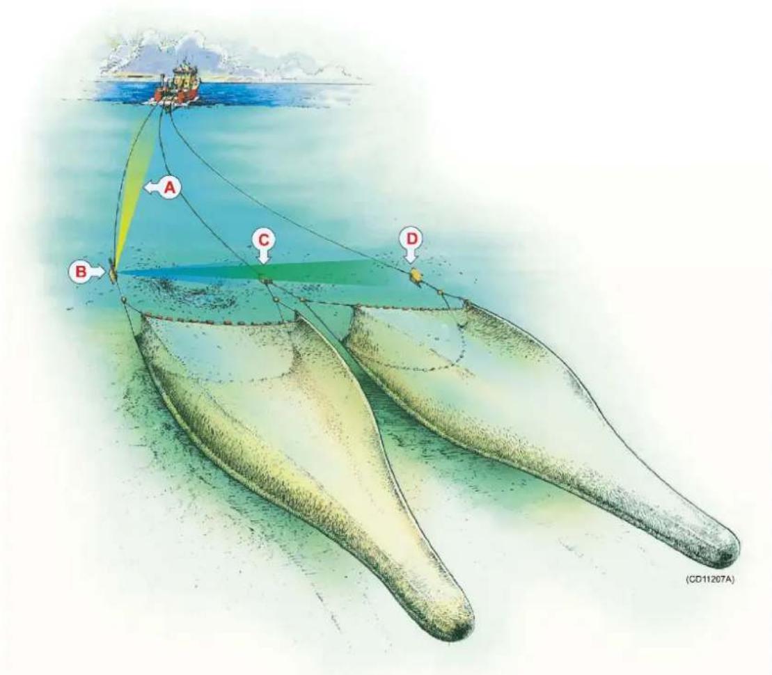
(A)=ThePITwinSpreadsensorcommunicateswiththePIsystemonthevessel.
(B)=ThePITwinSpreadsensorismountedontheporttrawldoor.
(C)=OnePIRemotesensorismountedonthecenterclump.
(D)=OnePIRemotesensorismountedonthestarboardtrawldoor.
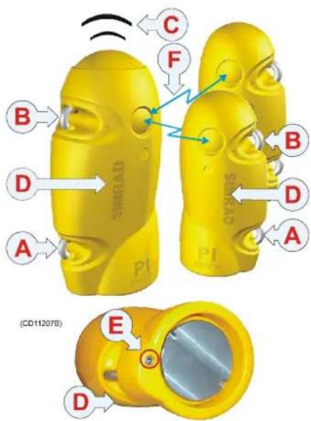
Mainparts
(A)=Negativechargingandfasteninglug
(B)=Positivechargingandfasteninglug
(C)=Communicationlinktothevessel
(D)=Locationofsensorlamp(rearsideofPI TwinSpread)
(E)=Waterswitchsensor
(F)=Transversecommunicationlinkstothetwo
Remotesensors
Dailyoperation
Onceinstalledandputtouse,theTwinSpreadsensorwill automaticallybeswitchedononcethewaterswitchisactivated. Afteraninitialstartup,thesensorstartsinterrogatingthe Remotesensorstomeasurethetwodistances.Theresultsare transmittedtothevessel.Whenthesensorsarenotinuse,check thatthesensorlamps(D)donotflashfromtimetotime,asthis indicatethatthesensorisonandisdischargingitsbatteries.In thiscase,washthesensorinfreshwatertoremovesaltanddirt.
If you operate with Fastupdaterate, the sensors must be charged approximately every 24 hours. Used with Normalor Slowupdaterates, the operation all life is approximately 48 or 70 hours respectively. For the Remotesensors, the batteries will last approximately 50, 100 and 150 hours respectively. The optimalsensor charging temperature is from +10 to +25°C.
Note: Thetworubberinsertsprovidedatthebottomofeachsensor adaptermustnotbereplacedwithanyothertypesordesigns.It isessentialthattheseinsertsprovideasecurecradleforthe sensors,buttheymustalsoallowforfreewatercirculationto allowthesensor'swaterswitchtoengage.Also,thedesignof theinsertsallowssandandmudtoflowoutwhenthetrawl doorsarepulledupfromthewater.
Note: Notethatchargingsensorsatsub-zerotemperaturescancreate explosivegasses.SimradASassumesnoliabilityforthe improperchargingofsensorsortheuseofchargersnot specifiedinSimrad'ssensorchargingdocumentation.
Numericalpresentation
OnthePI44display,thedistancesbetweenthetrawldoorsare displayedinthenumericdisplay.Tworectanglesareused,one foreachdistance.Ifthedistanceisincreasingordecreasing,this isshownwithtwoarrowsandthevariationinmetersper second.
When thereadingsarestable, the digits are shown in black colour. Whenthe values are predicted, the digits are grey, and if the contact is lost, the characters **.* a r e s h o w n i n g r e y . The characters ± ±. indicate that the Twin Spread sensor has lost contact with the Remotesensor(s), while characters??. means that the Remotesensors are out of range.
![A B C E D E S1 [m] 34.5 1 F G H () S3 [m] 68.9 >0.5](/content/2026/05/1048044/images/9ad9a1a0512b458173da58c489bb0756eefcbfb7ef160aef85811ce7023383f1.jpg)
(A)=TwinSpreadsensorsetupas sensorno.1.
(B)=Thedistanceaaremeasuredin meters.
(C)=Currentdistancebetweenthe portdoorandthecenterclump.
(D)=Thedistanceisincreasingby1 meterspersecond.
(E)=Arrowspointing "out" means that the distance is increasing. Arrowspointing "in" mean that it is decreasing.
(F)=Graphicalarm
(G)=Indicator,litforeverysensorinterrogation.
(H)=Interferencesymbol.
Thebottomnumericdisplayshowsthedistancefromtheport doortothestarboarddoor,andindicatesthatthedistanceis decreasingwith0.5meterspersecond.
Sensorconfiguration
YoucanoperatetwosetsofTwinSpreadsensors,thesesetsare identified as Twin Spread 1 and Twin Spread 2.
Twin Spread 1 uses two Remote sensors: Remote 1 and 2.
Twin Spread 2 uses two Remote sensors: Remote 2 and 4.
Ondelivery, all TwinSpread sensors are configured as Twin Spread 1 in Channels 2 and 5, with Fast update rate, and for use with Remote sensors 1 and 3. The four Remote sensors can be ordered pre-programmed from Simrad, but if you wish to use a TwinSpread2 set up you must re-configure a TwinSpread1 sensor using the PI Configurator utility.
Note: The TwinSpreadsensor and the PI44 system setup must also correspond, otherwise communication will not work.
Thesensorupdateratecontrolshowoftenthesensorreadsand reportsthedoorspread.Threesettingsareavailable.Notethata fasterupdateratewilldecreasethebatterylife.
- Fast(\~5,5sec):Recommendedfornewtrawlorgearor changesinriggingtomonitoranyinstabilitiesorunexpected changes.Thismodeprovidestheshortestbatterylifebefore charging.
- Normal(\~14sec):Recommendedforwellknowntrawl,gear anddoorbehaviorwithstablesituations. Usethissetting duringnormalconditions.
- Slow(\~34sec):Recommendedtomonitoringastable situationovertime, focusondoornotfallingover, broken sweeplinesetc.duringthetow. ThePI44systemwillbe moresensitivetobadcommunicationconditionsduetoslow dataupdate. Thismodeprovideslongestoperationalbattery lifebeforecharging.
System configuration
Sensorconfiguration: Thesensormustbeconfiguredwitha uniquesensornumber.Selectchannelnumberandupdaterate accordingtothesensor's configuration.Writedownthe configurationforfuturereference.
Status & Receiver: The Interference filter must be switched on. Setittolevel9ifyouhavenoiseproblemsfromother hydroacousticsources.Notethatwiththefilteron,itwill influencethesignalspectrumshownintheStatusdisplay.
Sensor filter: Switch this filter to Light. Set it to Heavy only if you experience excessivenoise.PositionOffwillprovideraw data and fastest possibleresponse.
Mounting
TheSpreadandRemotesensorsmustbemountedinspecial adaptersoneachtrawldoorandonthecentreclump. These adaptersmustbeinstalledaforehand. Detailedinformationon howtoinstalltheadaptersareprovidedwiththeinstallationkit.
Installationprinciple
ThePITwinSpreadsensorismountedontheportdoor.OnePI Remotesensorismountedonthecenterclump,whiletheother Remotesensorismountedonthestarboarddoor.Itisessential thatthereisaclearlineofsightbetweenthetransverse communication“eyes”(oneoneachsensor),andbetweenthe topofthePITwinSpreadsensorandthehydrophoneonthe vessel.
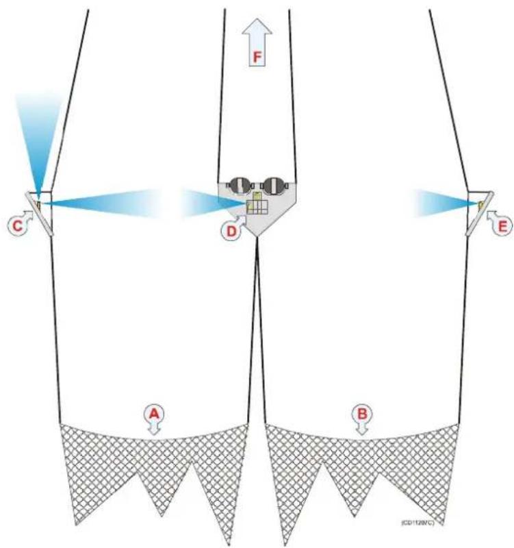
Topview:
(A)=Porttrawl
(B)=Starboardtrawl
(C)=Portdoorwiththe PITwinSpreadsensor mountedinanadapter. Oneacoustic communicationlinkis directedforwardtowards thevessel,whiletwoare directedtowardsthettwo Remotesensors.
(D)=Centerclumpwith oneRemotesensor
(E)=Starboarddoorwith theotherRemotesensor
(F)=Forward
InaTwinSpread1set-up, thetworemotesensors wouldneedtobeRemote 1andRemote3.
Sacrificialwaterswitchsensor
Ifthewaterswitchonyoursensorisasacrificialbrassscrew, thisscrewmustbecheckedeverymonth. Wheneverrequired duetowearandtear,thescrewmustbereplaced.Refertothe Operationalproceduresintheoperatormanual.
PI Temperature sensor
Purpose
The PIT temperaturesensormonitorsthecurrentwater temperatureatthechosenlocationonthepurseseineortrawl.

(A)=ThesinkingrateofthenetismonitoredbytwoDepth sensors
(B)=OneTemperaturesensorismountedonthefootropeto monitorthelocationofthethermo-cline.

natural_image
Illustration of a large ship deploying a coastal structure with visible cables and equipment, no text or symbols present.(C)=OneTemperaturesensorismountedontheheadropeto monitoriftheseawatertemperatureisfavourableforthetarget species.

Mainparts
(A)=Negativechargingandfasteninglug
(B)=Positivechargingandfasteninglug
(C)=Communicationlink
(D)=Locationofsensorlamp
(E)=Waterswitchsensor
(F)=Temperaturesensor(labelisremoved)
Dailyoperation
Onceinstalledandputtouse,thesensorwill automaticallybeswitchedononcethe waterswitchisactivated.Afteraninitialstartup, thesensorstartstransmissionofthecurrent temperature.Whenthesensorisnotinuse,check thatthesensorlamp(D)isnotflashingfromtime totime,asthisindicatesthatthesensorisonand isdischargingitsbatteries.
If you operate with Fastupdaterate, the sensor must be charged approximately every 24 hours. Used with Normal or Slow update rates, the operational life is approximately 75 or 150 hours respectively. The optimal sensor charging temperature is from +10 to +25°C.
Notethatchargingsensorsatsub-zerotemperaturescancreate explosivegasses.SimradASassumesnoliabilityforthe improperchargingofsensorsortheuseofchargersnotspecified inSimrad'ssensorchargingdocumentation.
Temperaturepresentation
OnthePI44display, the temperature is displayed in the numeric display. If the temperature is falling or rising, this is shown with an arrow. When thereadings are stable, the digits are shown in black colour. When the values are predicted, the digits are grey, and if the contact with the sensor is lost, the characters ^* . **are showing grey.

(A)=Sensorsetupassensorno.2.
(B)=Currenttemperature.
(C)=Denomination(Celciusor Fahrenheit)
(D)=Temperaturechange. This arrowindicates that the temperature is rising.
(E)=Graphicalarm
(F) = Indicator,litforeverysensor interrogation.
(G)=Interferencesymbol.
Sensorconfiguration
Ondelivery, alltemperaturesensorsareconfiguredinChannel8 and with Fast update rate. If you use more than one sensor, you mustsetthemuptooperateindifferentchannels.
Note: ThesensorandthePI44systemsetupmustcorrespond, otherwisethecommunicationwillnotwork.
Tochangethesensorsetup(channelselection), usethe PI Configuratorutility.
Thesensorupdateratecontrolshowoftenthesensorreadsand reportsthetemperature.Threesettingsareavailable.Notethata fasterupdateratewilldecreasethebatterylife.
- Fast(\~4,5sec):Recommendedforpurseseineortrawl, allows immediate update of changes in these at temperature.
- Normal(\~14sec):Recommendedfortrawlandnormal fishingwithfairlyconstantseatemperatures.
- Slow(\~34sec):Recommendedifyouexperienceconstant seatemperatures,orifmaximumoperationalbatterylife beforechargingisrequired.Thesystemwillbemore sensitivetobadcommunicationconditionsduetotheslow dataupdate.
System configuration
Sensorconfiguration: Thesensormustbeconfiguredwitha uniquesensornumber.Selectchannelnumberaccordingtothe sensor's configuration.Writedowntheconfigurationforfuture reference.
Status&Receiver:TheInterferencefiltermustbeswitchedon. Setittolevel9ifyouhavenoiseproblemsfromother hydroacousticsources.Notethatwiththefilteron,itwill influencethesignalspectrumshownintheStatusdisplay.
Sensor filter: Switch this filter to Light. Set it to Heavy only if you experience excessivenoise.PositionOffwillprovideraw data and fastest possibleresponse.
Mounting
Purseseine: Inordertosecurestablecommunicationwiththe vessel'shydrophone, it is very important that the sensoris allowed to hang freely with the endpoint pointing towards the surfaced uringshooting and pursuing.
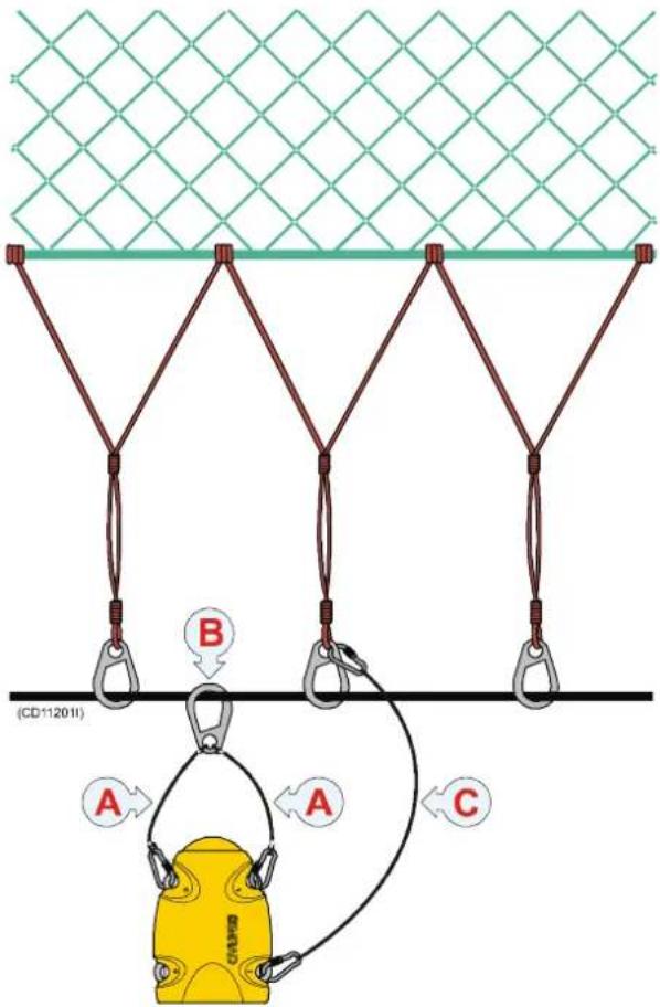
Attachthesensortoastandardpurse ringwithtwoseparatewires(A). Mountoneendofeachwiretoa commonsnaphook(B),andplace anothersnaphookattheotherendof eachwiretosnapontothesensor.
Mountasafetyline(C)between the sensorandtheadjacentbridle/purse ring. Makesurethatsecuritylinedoes notpreventthesensorfromhanging freely!
Removethesensorfromthepurse seinebeforeitpassesthroughthe powerblock.
Anyattachmentmaterial "permanently"attachedtothe sensor'scharginglugsmustnotform anelectricalconnectionbetweenthe twocharginglugsshortingthe chargingcurrent.
(A)=Twowireswithasnaphookin oneendandtheotherendattached permanentlyto(B).
(B)=Largesnaphook.
(C)=Safetywirewithsnaphookson eachend. Notethattheupperendis NOTattachedtothepurseseinewire.

Tunapurse: Thesensormustnotbe attachedtothefootropewire, butto thefoot-ropechain. Useasafetywire inadditionincasethesensorisripped offthenet.

natural_image
Diagram of a yellow mechanical component with two arms and chains, mounted on a chain-link base against a green mesh background (no text or symbols)TrawlorDanishseine: Thesensoris normallyattachedtotheheadrope. Forsecurefasteningandstable positioningofthesensorpointing towardsthevessel,makeafinemesh bagsizedtothemiddleofthe head-rope.Sizetwosnaphooks approximately 10-15cmfromthe headropeformingabridle,andkeep thesensorstretchedbymeansoftwo rubberstrapsattachedtotheaft fasteninglugs.
Sacrificialwaterswitchsensor
Ifthewaterswitchonyoursensorisasacrificialbrassscrew, thisscrewmustbecheckedeverymonth. Wheneverrequired duetowearandtear,thescrewmustbereplaced.Refertothe Operationalproceduresintheoperatormanual.
PS Temperature sensor
Purpose
ThePSTemperaturesensormonitorsthecurrentwater temperatureatthechosenlocationonthepurseseineortrawl.

(A)=ThesinkingrateofthenetismonitoredbytwoDepth sensors
(B)=One Temperature sensor is mounted on the footropeto monitor the location of the thermo-cline.

natural_image
Illustration of a large ship deploying a coastal structure with visible cables and no text or symbols(C)=OneTemperaturesensorismountedontheheadropeto monitoriftheseawatertemperatureisfavourableforthetarget species.

Mainparts
(A)=Negativechargingandfasteninglug
(B)=Positivechargingandfasteninglug
(C)=Communicationlink
(D)=Locationofsensorlamp
(E)=Waterswitchsensor
(F)=Temperaturesensor(labelisremoved)
Dailyoperation
Onceinstalledandputtouse,thesensorwill automaticallybeswitchedononcethe waterswitchisactivated.Afteraninitialstartup, thesensorstartstransmissionofthecurrent temperature.Whenthesensorisnotinuse,check thatthesensorlamp(D)isnotflashingfromtime totime,asthisindicatesthatthesensorisonand isdischargingitsbatteries.
YoucanonlyoperatethissensorwithFastupdate rate. Thesensormustthenbecharged approximately every 30 hours. The optimal sensorcharging temperature is from +10 to +25°C.
Notethatchargingsensorsatsub-zerotemperaturescancreate explosivegasses.SimradASassumesnoliabilityforthe improperchargingofsensorsortheuseofchargersnotspecified inSimrad'ssensorchargingdocumentation.
Temperaturepresentation
OnthePI44display, the temperature is displayed in the numeric display. If the temperature is falling or rising, this is shown with an arrow. When thereadings are stable, the digits are shown in black colour. When the values are predicted, the digits are grey, and if the contact with the sensor is lost, the characters ^* . **are showing grey.

(A)=Sensorsetupassensorno.2.
(B)=Currenttemperature.
(C)=Denomination(Celciusor Fahrenheit)
(D)=Temperaturechange. This arrowindicates that the temperature is rising.
(E)=Graphicalarm
(F)=Indicator,litforeverysensorinterrogation.
(G)=Interferencesymbol.
Sensorconfiguration
Ondelivery, alltemperaturesensorsareconfiguredinChannel8 and with Fast update rate. It is not possible to change the update ratesetting. If you use more than onesensor, you must set them up to operate indifferent channels.
Note: ThesensorandthePI44systemsetupmustcorrespond,
otherwisethecommunicationwillnotwork.
Tochangethesensorsetup(channelselection), usethe PI Configuratorutility.
Thesensorupdateratecontrolshowoftenthetemperatureis measured, and the datatransmitted to the vessel. Tobeableto monitor fast changes in these atemperature, the sensor will only operate on Fast updaterate.
System configuration
Sensorconfiguration: Thesensormustbeconfiguredwitha uniquesensornumber.Selectchannelnumberaccordingtothe sensor's configuration.Writedowntheconfigurationforfuture reference.
Status&Receiver:TheInterferencefiltermustbeswitchedon. Setittolevel9ifyouhavenoiseproblemsfromother hydroacousticsources.Notethatwiththefilteron,itwill influencethesignalspectrumshownintheStatusdisplay.
Sensor filter: Switch this filter to Light. Set it to Heavy only if you experience excessive noise. Position Off will provide raw data and fastest possibleresponse.
Mounting
Purseseine: Inordertosecurestablecommunicationwiththe vessel'shydrophone, it is very important that the sensoris allowed to hang freely with the endpoint pointing towards the surfaced uringshooting and pursuing.

Attachthesensortoastandardpurse ringwithtwoseparatewires(A). Mountoneendofeachwiretoa commonsnaphook(B),andplace anothersnaphookattheotherendof eachwiretosnapontothesensor.
Mountasafetyline(C)between the sensorandtheadjacentbridle/purse ring. Makesurethatsecuritylinedoes notpreventthesensorfromhanging freely!
Removethesensorfromthepurse seinebeforeitpassesthroughthe powerblock.
Anyattachmentmaterial "permanently"attachedtothe sensor'scharginglugsmustnotform anelectricalconnectionbetweenthe twocharginglugsshortingthe chargingcurrent.
(A)=Twowireswithasnaphookin oneendandtheotherendattached permanentlyto(B).
(B)=Largesnaphook.
(C)=Safetywirewithsnaphookson eachend. Notethattheupperendis NOTattachedtothepurseseinewire.

Tunapurse: Thesensormustnotbe attachedtothefootropewire, butto thefoot-ropechain. Useasafetywire inadditionincasethesensorisripped offthenet.
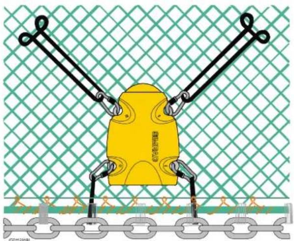
natural_image
Diagram of a yellow mechanical component with two arms and chains, mounted on a chain-link base against a green mesh background (no text or symbols)TrawlorDanishseine: Thesensoris normallyattachedtotheheadrope. Forsecurefasteningandstable positioningofthesensorpointing towardsthevessel,makeafinemesh bagsizedtothemiddleofthe head-rope.Sizetwosnaphooks approximately10-15cmfromthe headropeformingabridle,andkeep thesensorstretchedbymeansoftwo rubberstrapsattachedtotheaft fasteninglugs.
SENSOR CHARGERS
Overview
TwodifferentbatterychargerscanbeusedtochargethePIand PSsensors:
- PICharger
- PS30Charger
Event though both chargers can be used to charge any of the sensors (except the PI Height sensor), only the PI Charger will provide fast and intelligent charging of the PIsensors.
Note: ThePIHeightsensorcanonlybechargedwiththePICharger.
Topics
→ PICharger,page165
→ PS30Charger,page167
PI Charger
Purpose
ThePIChargerisanintelligentbatterychargerforfastand securechargingofthePIsensors. Thechargerwill automaticallysetupthecorrectchargingcurrentdependingon thesensortypeandthebatterytemperature.EventhoughthePI ChargerisdesignedforfastchargeofthePIsensors,itcanalso chargethePSsensors,butonlyatnormalchargerate.Afuel metershowsthestatusofthebatteryduringthecharge.
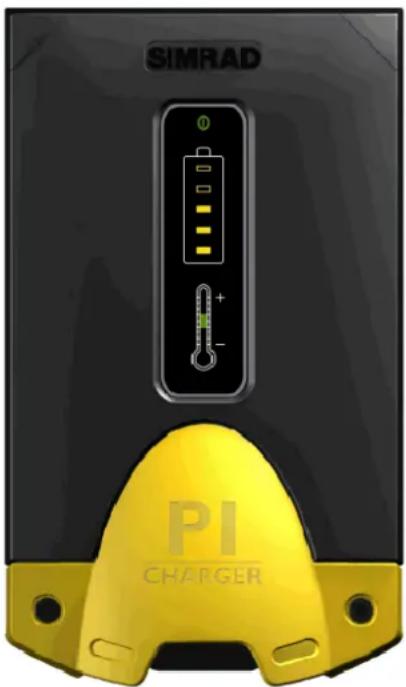
Dailyoperation
1) Attach the charging clamp stothesensor as follows:
Redclamp: Positive fastening lug(+)
Blackclamp: Negative fastening lug(-)
2) Ensure that attachment materials, rope etc. donot short circuit the charginglugs, preventing charging and causing damage to the sensorlugs.
Onceconnected,thechargerwillidentifywhether thesensorconnectedcanbefastchargedornot. Thebatterytemperaturewillalwaysbemonitored forafastchargingsensor.Asensorwhichcannot befastcharged,willnotdisplaythebattery temperature,andthetemperatureLEDwillbe dark.
3) Observethechargetimesandtemperaturelimitations:
Fastcharge: Firstapproximately 1 hour for 70% battery capacity, then approximately 3 hour store each 100% capacity. Once fully charged, a constant trickle chargewill compensate for self discharging. Not that fast charging appliesto PI sensor only!
Normalcharge: 16 hours for full battery capacity. This mode applies for charging outside specified temeparture range, and for all PS sensors.
Chargingtemperature:Forbestresults,keeptheambient temperaturebetween+10and+25°C.Donotchargein temperaturesabove+50°Corbelow0°C!

Indicators
(A)=Mains:12to32Vdc
(B)=Fuelmeter. ThenumberofLEDsilluminatedshowsthe currentchargingstatus. Acompletechargingcycleisindicated withall“full”battery.Charging:
Fast: Fast flash
Normal: Slowflash
Trickle: On, off every 4 second
(C)=Batterytemperatureindicatorsduringfastcharging:
Green: Battery temperature between +5 and +40°C. Fast chargeisenabled.
Green and Blue: Battery temperature between 0 and +5°C. Fastcharge is disabled, normal charge is used.
Green and Red: Battery temperature between +40 and +50°C. Fastchargdisabled, normalchargeisused.
Blue: Battery temperature is below 0^ C. No charging takes place.
Red: Batterytemperatureisabove+50°C. Nocharging takes place.
Warning:Chargingasensoratsub-zerotemperaturemight developexplosivegasesrepresentingapotential danger.Simradassumesnoliabilityforimproper charging, or the use of other chargers than those approvedbySimrad.
Automaticconfiguration
Thechargercommunicateswiththesensoratregularintervals. Thefastchargecycleiscontrolledbydataexchangedbetween thePIsensorandthecharger,andaseriesofsafetymechanisms controlstheterminationofthefastchargingcurrent.
The PS sensors donot communicate with the charger. A constant charge current of 58 mA isthen setup by the charger regardless of the battery temperature.

Typicalsensor(PI Depth)
(A)=Negativecharging/fasteninglug
(B)=Positivecharging/fasteninglug
(C)=Communicationlink
(D)=Locationofsensorlamp
(E)=Waterswitchsensor
ThePSChargerisabatterychargerforsecurechargingofthe PSandPIsensors.

natural_image
Yellow electroplating device connected to a SIMPAD sensor device via cable (no visible text or symbols on the device itself)Dailyoperation
1) Attachthechargingclampstothesensorasfollows:
Redclamp:Positivefasteninglug(+)
Blackclamp:Negativefasteninglug(-)
2) Ensure that attachment materials, rope etc. does not short circuit the charging lugs, preventing charging and causing damage to the sensor lugs.
3) Observethesensor'sindiactorlamp.Itwillflashonceevery foursecondsduringcharging.
4) Observethechargetimesandtemperaturelimitations:
Normalcharge:\~16hoursforfullbatterycapacity.
Chargingtemperature: Toobtainbestresults, trytokeep the ambient temperature between +10°C and +25°C. The sensormust not be charged in temperatures above +50°C or below 0°C!
Warning:Chargingasensoratsub-zerotemperaturemight developexplosivegasesrepresentingapotential danger.Simradassumesnoliabilityforimproper charging,ortheuseofotherchargersthanthose approvedbySimrad.
Generalguidelines
Operationaltimeandservicelifeofthesensor'sNiCdbattery dependsonproperuseandregularcharging. Observethe followingprecautions, asthesewillhaveaninfluenceonthe batteryperformance:
- Observethechargingtemperatures.
- Chargesensors regularly. Avoiddrainingthesensorbattery completelybeforecharging.
- Chargethesensorbatterybeforestorage, and at three-month intervals under long-term storage.
- Operationallifemaybeinitiallyreducedafterlong-term storageorchargingforalongtime.
- Sensorsarenotdamagedbybeingleftattachedtoacharger forseveraldays. However, donotstorethesensorfor extendedperiodsundercharge.
- Werecommendthatawoodenboxismadetokeepthesensor inasecureplaceduringchargingandstorage.Makeopenings inthebottomtodrainforseawater.
Batterydepletedfrequently
If the charger lamp is illuminated, but the sensor lamp does not flare every four seconds, the battery is not being charged properly. Most likely, this is because the sensor was not switched off when the charger was connected.
Tocorrect, chargethesensorfortenminutes, thendisconnect thealligatorclips. Useasmallwire, and makecontactbetween thewaterswitchsensorandoneofthefasteninglugs. This will causethesensortoflashitsstart-upcode. If not, washthesensor infreshwatertodisengagethewaterswitch.

Typicalsensor(PI Depth)
(A)=Negativecharging/fasteninglug
(B)=Positivecharging/fasteninglug
(C)=Communicationlink
(D) = Location of sensor lamp
(E)=Waterswitchsensor
(F)=Waterpressuresensor
MENU SYSTEM
ThePI44iscontrolledusingasmallmenysystem. Although severalshortcutsexist, themainfunctionsandsetupparameters can be accessed from themainmenu. To access themainmenu, presstheMENUbutton.
Topics
→ Mainmenu,page170
→ Echoquickmenu,page172
The main menu
Toaccesstheimainmenu, presstheMENUbutton.

(CD11034B)
Fishery
OntheFisherymenu,youcanselectdisplaymodesrelatedto catchmonitoring.
→ Numericdisplay,page33
→ Graphicdisplay, page41
→ Surfacetemperature, page45
→ Statusdisplay, page46
Echo
OntheEchomenu,youcanselectdisplaymodesrelatedtothe built-inechosounder.Twomodesareavailable.Theyare howeveridenticalusingtwodifferentfrequencies.
→ EchoxxkHz,page50
Navigation
OnthePilotmenu,youcanselectdisplaymodesrelatedto vesselnavigation.
→ Position, page54
→ Highway, page53
Setup
OntheSetupmenu,youcanaccesssetupparameterstocontrol theoperationofthePI44.
Notethatadditionalparametersareaccesseddirectlyfromthe presentations by pressing the ADJ and/or ENT buttons.
→ Echosoundersetup,page180
→ Pilot/Positionsetup,page200
→ Speedalarm, unitsandlanguage:
→ Speedalarm,page217
→ Units,page225
→ Language,page204
→ Interfacesetup,page187
→ Sensoralarm/calibration, page211
→ Sensorsetup,page215
→ Receiversetup,page208
→ Palettesetup,page205
→ Factorysettings,page183
→ Quickguide, page207
Echo quick menu
To access the Echo quick menu, press the ENT button while operating with an echosounder in the active window.
Choices
→ Changefrequency,page54
→ ActivateA-Scope,page52
→ Activatedepthbars,page43
→ Graphicsetup,page184
→ Echopresentationsetup,page177
→ Transmitpoweron/off,page177
If you press the ENT button while operating in other modes, you will access the applicable setup menus.
REFERENCES
Thischaptercontainsreferenceinformation.Itthusprovides detailedinformationaboutthevariousparametersusedto controltheoperationandperformanceofthePI44system.You donotneedtoreadandunderstandthicchaptertooperatethe PI44,buttheinformationmayguideyoutoamoreefficientuse.
Thesetuppagesareprovidedinalphabeticalorder.Someare accessed from the Setup menu, others directly from the display presentationsbymeansoftheADJbutton.
Topics
→ Depthcalibration,page176
→ Echopresentationsetup,page177
→ Echosoundersetup,page180
→ Factorypresets,page183
→ Graphicsetup,page184
→ Interfacesetup, page187
→ Markerlinesetup,page197
→ Navigationsetup, page200
→ Numericsetup, page202
→ Offsetadjust,page203
→ Pagesetup,page204
→ Palettesetup,page205
→ Positiondisplaysetup,page206
→ Quickguide, page207
→ Receiversetup, page208
→ Sensoralarm/calibration,page211
→ Sensorsetup,page215
→ Speedsetup,page217
→ Statussetup,page218
→ Surfacetemperaturesetup,page219
→ Temperaturesetup, page220
→ Trawlcalculator, page221
→ Trawlinfosetup,page223
→ Unitssetup, page225
Setup map
The various setup dialogues controlling the PI44 behaviour can be accessed from several places. The tables below provide an oversight.
Accessfrom the display presentations
| DisplaypresentationPressADJto access: | PressENTto access: | |
| NumericalNumericsetup | Numericsetup | |
| GraphicGraphicsetup | TemperatureMarkerlineTrawlinfoTrawlcalculator | Echoquickmenu |
| SurfacetemperatureSurface | temperaturesetup | Surface temperaturesetup |
| StatusStatussetupStatus | setup | |
| EchoEchopresentation | setup | Echoquickmenu |
| Highway (Navigation) | Navigation setup | Navigation setup |
| Position | Positiondisplay setup | Positiondisplay setup |
AccessfromtheEcho quick menu
| Menuoption | Accesstosetupdialogues: |
| Changefrequency | N/A |
| A-Scope | N/A |
| Depthbars | N/A |
| Graphicsetup | GraphicsetupTemperatureMarkerlineTrawlinfoTrawlcalculator |
| Echopresentation setup | Echopresentationsetup |
| Transmitpower | N/A |
Accessfrom the Setupmenu
| MenuoptionAccesstosetupdialogues: | |
| EchosoundersetupEchosoundersetup | |
| NavigationsetupPilot/Positionsetup | |
| Speedalarm,units andlanguage | Setupforspeed Setupforunits Language Pagerotation |
| InterfacesetupNodes | PIFunction Position Navigation Water Alarm SimNetdiagnostics SimNetinput SimNetoutput NMEA0183input NMEA0183output Identification |
| Sensor alarm/calibration | Sensoralarm Surfacetemperature Clearance Depthcalibration Offsetadjust |
| SensorsetupSensorsetup | |
| ReceiversetupReceiversetup | |
| PalettesetupPalettesetup | |
| FactorysettingsFactoryypresets | |
| QuickguideQuickguide | |
Depth calibration
ThisfunctionisusedtoenablecalibrationofthePI44Depth sensor.
To access this function, press the MENU button to open the main menu. Then, open the Setup menu, and select Sensor alarm/calibration.
Whentheredialogueopens, press the GAIN + button a few times to open the Depth calibration dialogue.

The Depthcalibrationfeaturewillcalibratethecurrentdepth of the Depthsensortoone-1-meter.
1Lowerthesensoroverthesidetoadepthofonemeter, to acertaindraftdepthplusonemeter, ortoanyreference levelthatyouwishtobedefinedasonemeter.
2Oncethereadingfromthesensorisstable,setDepth sensorcalibrationtoYES.
Thecalibrationtakesoneminute. While the process is running, then numerical presentation is shown with grey text. Not that the sensor must be submerged into salt water to perform the calibration.
Related topics
→ Howtocalibratethesensor,page65
→ PIDepthsensor,page124
→ PSDepthsensor,page129
Echo presentation setup
Thesesettingsareusedtosetuptheechosounderpresentation parametersonthePI44. Theoperationalparametersaresetup usingtheEchosoundersetupdialogue.
Toaccesstheparameters, presstheADJ(Adjust)buttonwhen youhaveanechosounderpresentationintheactivewindow. You can also press the ENT button, and then select Echo presentation setup on the Echo quick menu.
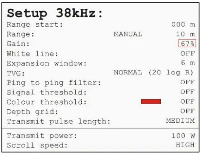
(CD11103C)
Rangestart: This is the upper depth from which you wish the echosoundershall start. This value will typically be 0 meters, but you may fore examples setup the echosoundert oonly present echoes from 5 meters below these as surface and downwards.
Range: Thisistheverticaldepthrangefortheechosounder. Youcansetittochangedepthrangeautomatically(AUTO), or youcandefinyourownfixedrange. Themaximumrangewill dependonthechosenechosounderfrequency, asthe38or50 kHzmodeswilldetectechoesdeeperthanthe200kHzmode.
Gain: Thisisthegainintheechosounder'spreamplifier. The gainmustbedefinedmanually, and you can choose any value between 1 and 100% . In most cases, use a value around 60% . If you set to much gain, the echogram will contain a lot of noise and false echoes.
Whiteline: This parameter allows y outoswitch the Whiteline functiononoroff. When enabled, abandin the current echogram background colour is inserted immediately below the detected bottom depth.
Expansionwindow:ThePI44providesbottomexpansionand zoomfunctions.Whenoneoftheseisenabled,youcancontrol thedepthrangeintheexpandedwindowusingthisparameter.Toenablethebottomexpansionfunction,presstheB-LCK buttononthekeypad.Toenablethezoomfunction,pressthe ZOOM button.To disable both,press the STND or SHIFT buttons.YoucanalsoaccessthisparameterintheGraphic setup.
TVG(Time VaryingGain): The PI44 provides a TVG function to enhance the echoes from deeper waters. You can switch the TVG to OFF (not recommended), or select either Special (40 log R) or Normal (20 log R) setting, depending on your preferences. For all normal operation, leave it at Normal. Try specialify you are looking forechoescloseto these abedindeeperwaters.
Pingtopingfilter: This function employs a filter which compares the echo information from one ping with the information from the previous ping. This will “cleanup” the echogram by removing random noises spikes and interference with no correlation with the previous echo. The function will thus make the echoes appear more stable. You can switch this filter on or off.
Signalthreshold: This is an on/off function. When activated, it will remove the weakest echoes from the screen. The threshold level is automatic. Activate with caution, as it may remove small fish or other weak unidentified echoes from the presentation.
Colour threshold: This function allows you to choose the numberofcolourstouseforechogrampresentation.By switchingthisfilteronandselectingacolourinthebox,all echocolours“below”thechosencolourwillnotbeshowninthe echogram.Youcanthusregardthisasan“echothreshold” whichwillremovetheweakestechoes.
Depthgrid: Whenthisfunctionisenabled, thinhorisontaldepth lineswillbeaddedtotheechogramtoeasieridentifythedepth intervals. Whenyouoperatewithagraphicdisplay, thisfunction canalsobeswitchedonandoffintheGraphicsetup.
Transmitpulselength: This parameter allows you to choose the length of the echosounders pulse transmissions. You can choose OFF (to observ the ambient seanoise), SHORT, MEDIUM, LONG or AUTO. In most cases, select AUTO. The PI44 will then automatically choose the pulselength depending on your current depth range. If you choose to try a manual mode, try long pulselengths when you operate in deeper waters, and shorter pulses with higher frequency in shallower waters.
Asageneralrule, shortpulsesservetomaketheechoes from variousobjectsmoredistinct. It is therefore used to obtain optimal vertical resolution, as it will separate individual fishes from each other and from the bottom. Longer pulses will penetrate deeper, but with less resolution.
Transmitpower: This parameter allows you to change the power output from the echosounder. You can choose OFF (and nochogram will appear!), 10W, 100W, 500W, 1000W or AUTO. In most cases, select AUTO. The echosounder will then automatically adjust the power output depending on the current operational frequency and the current depth.
Scrollspeed: This function control show fast the presentation shall scroll from right to left across the display. By defining this speed you also control the timescale. If you slowdown the scroll speed, you will also increase the time between each echo sounder transmission (ping). If you choose FREEZE the presentation (and also the echosounder transmissions) will stop altogether. Not that this parameter can also be set in the
Graphicsetup.
Note: Theechosounderfrequencyyouchoosemustbesupportedby thetransduceryouhaveinstalled!
Related topics
→ Howtodefinetheechosounderrange,page91
→ Echosoundersetup,page180
→ Graphicsetup,page184
→ Bottomexpansion,page51
Echo sounder setup
Thesesettingsareusedtosetuptheoperationalparametersfor thePI44echosounder.
Toaccessthedialogue, presstheMENUbuttonontoaccessthe main menu. Then, open the Setup menu, and select Echo soundersetup.
Notethatthepresentationparametersaredefinedinaseparate dialogue;theEchopresentationsetupdialogue.
| Echo sounder setup: | ||
| Select transducer: TYPE Transducer 1: ECHO2S BEAM ANGLE DEPTH Transducer 1: 12/07° 02.3 m | ||
| Keel depth below surface: 02.6 m Display: DEPTH BELOW KEEL Data on NMEA-out from: 50kHz Alarm for fish: Strength: 065% OFF Depth DS fish: min:0010m max:0100m Depth DK alarm min: 0010m OFF Depth DK alarm max: 0100m OFF Water profile: SALT Velocity of sound in water: 1470m/s Time scale: ON Restart of AUTO pulse/power: 20 sec. Echo sampling: BOTTOM Demo mode: OFF | ||
| MENU Exit Accept ENT |
Transducerinstallation
Note:
TheupperpartoftheEchosoundersetupdialogueisusedto defineandsetuptheechosoundertransducer(s)usedonthe PI44.Thisoperationisonlycarriedoutonce,andthatisduring thesysteminstallation.DONOTADJUSTthesettingsduring normaloperationoftheechosounder,asincorrectsettingsmay resultindamagetothePI44and/orthetransducer(s).
Formoredetailedinformationontransducerinstallation,consult thePI44installationmanual.
Selecttransducer: Enterthetype and main parameters of each transducer connected to the PI44 system.
Transducertype: Entertransducertype. You can leaf through a number of predefined transducertypes, or define your own. Not that some of the predefined types are “dual” transducers, which mean that both transceiver outputsports (Echo1 and Echo2) will be used.
Transducerport: Enter which transceiver port (output) the transducer is connected to; Echo 1 or Echo 2. With the predefined transducertypes, the ports are also set by the software.
Transducerbeamangle: Enter therefore-and-aft and athwartships beam angles forthetransducer. With the predefined transducertypes, this information is already known.
Transducerdepth: Entertheverticaldistancebetween the transducerfaceandthewatersurface. Normally, thisvaluecan befixed, butifitchangesconsiderablywhenthevesselis loaded, youmayneedtochangeit. Thevalueisusedtoprovide youwithacorrectdepthunderkeel(DK)valueintheecho sounderpresentation.
Echosounderparameters
Keeldepthbelowsurface: Enterthedistancebetweenthekeel andthewatersurface. Normally, thisvaluecanbefixed, butifit changesconsiderablywhenthevesselisloaded, youmayneed tochangeit. Thisparameterisusedtoprovideyouwith the correctdepthbelowkeelvalueintheechosounderpresentation.
DataonNMEA-outfrom: Chooseiftheechosounderdata outputontheNMEAinterfaceshallbetakenfromthe38kHz, 50kHzor200kHzzechosounderfrequency.
Alarmforfish, strength: This parameter enables the fish detection alarm, and adjust the sensitivity (strength). With high sensitivity, smaller fish (with weakerechoes) will trigger the alarm.
D e p t h D S f i s h : Thisparameterallowsyoutodefineavertical deptharea(betweenamaximumandaminimumdepth)in whichthefishalarmcanbetriggered.Echoesoutsidethechosen areawillnottriggerthealarm.
DepthDKalarm(minimumandmaximumvalues): This parameterenablesanalarmtosoundoffifthewaterdepthunder thekeelisshallowerordeeperthantwopredefinedlimits.
Waterprofile: This parametersetsuptheechosounderfor operationinfreshorsaltwater.
Velocityofsoundinwater: This parameter allows you to fine the performance of the PI44 echosoundertothespeed of soundinthewater. However, in most cases, the accurates speed is not known, and this parameter is not important at all when operating in shallow waters. For all practical purposes, leave this setting to the default value of 1470 m/s.
Timescale: This parameter allows youtoswitch the timescale in the echosounder presentation on or off.
RestartofAUTOpulse/power:Ifyouhavesetthetransmit powerandpulselengthparameterstoAuto,theechosounder willautomaticallyrestarttheparametersatfixedintervalsto ensurecorrectsettings.Bymeansofthisparameter,youcan controltheintervals.Inmostcases,leavethissettingto20 seconds,whichisthedefaultvalue.
Echosampling: Using this function, you can select if the automatic pingrates shall be defined by the current depth or the current range.
Demomode: This parameter allows you to our the echosounder in a "demonstration" mode. When this mode is enabled, the echosounder will automatically use a "demotransducer" to avoid damage to the output circuitry.
Related topics
→ Echosounderdisplay, page50
→ Echopresentationsetup,page177
Factory presets
ThisfunctionallowsyoutorestorethePI44parameterstothe defaultsettingschosenbySimrad.

To access the presets, press the Menu key, and select Setup (4). Onthesubmenu, select Factorysettings. Once accessed, you havethe following choices:
(1):RestoretheSimNet/NMEAfactorypresets.Thiswillonly restoretheinterfaceparametersyouhaveselectedonthePI44. Anysettingsyouhavemadeforechosounderandsensor operationwillnotbeaffected.
(2):Restoretheechosounderfactorypresets. This will only affect the parameters related to echosounderoperation.
(3):RestorethePI44factorypresets.Thiswillonlyaffectthe parametersyouhavemadeconcerningsensorselectionand setup.Sensorsetupwillnotbeaffectedbythisreset,butthe Demomodewillbeswitchedoff.
(CLR): This will clear ALL current parameters and replace them with the factory presets.
Caution: If you choose CLR to return to all factory presets, you will need to redefine every single parameter you have made on the PI 44. This includes allechosounder settings, sensor selections and setup, system interfaces and alarms.
(0): This option will open a test display. This display is only provided for software debugging and maintenance use, and it will not give you any useful information. Toclosethetest display, press the MENU button.
Related topics
→ Howtorestoredefaultsettings,page101
Graphic setup
ThesesettingsareusedtosetupthePI44parametersrelatedto theGraphicdisplay.
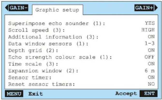
TheGraphicdisplayshowsthedatafromthesensorsintheir alphanumericalpresentations,aswellashistoricalplots sumperimposedontheechogram.Thedigitsinthe alphanumericalpresentationsareblackwhenthedataarevalid, theyaregreywhenthevaluesareonlypredicted,ortheyare replacedwithasterixcharacters(*)whenthecontactwiththe sensorislost.Theyellowpulselampisliteverytime informationinreceivedbackfromthesensor.Thepositioningof thealphanumericalpresentationsiscontrolledbytheorderof whichthesensorswereconfiguredintheSensorsetup dialogue.
Toaccesstheparameters, presstheADJbuttonwhenyouhave agraphicdisplayintheactivewindow. Youcanalsopressthe MENU button to access the Echo quick menu, and then select Graphicsetup.
Superimposeechosounder: When activated, the presentation from the echosounder is added to the graphic display. Not that this option is only valid if you have the echosounder transducer(s) installed, and the echosounder is setup for normal operation. You can only switch this function on or off.
Scrollspeed: This function control show fast the presentation shall scroll from right to left across the display. By defining this speed you also control the timescale. If you slowdown the scroll speed, you will also increase the time between each echo sounder transmission (ping). If you choose FREEZE the presentation (and also the echosounders transmissions) will stop altogether. Not that this parameter can also be set in the Echo presentation setup.
Additionalinformation: Thefeaturewilldisplayan informationbarbelowthenumericpresentationsontheGraphic display. Thebarprovideskeytechnicalpararametersrelatedto theechosounderoperation; frequency, outputpowerandpulse length. It will also show you the ambient air temperature, the vessel's speed and the current depth. If you set these selectorpad to adjust the depth of the VRM (Variablerangemarker) or the echosounder receiver gain, it will show your current depth and gain settings while you do this. The default setting is ON.
Depthgrid: Whenthisfunctionisenabled, thinhorisontaldepth lineswillbeaddedtothepresentationtoeasieridentify the depthintervals. Notethatthisfunctioncanalsobeswitchedon andoffintheEchopresentationsetup.
Datawindowsensors: WhenyouhavesetuptheGraphic displayononlyahalfscreen, thereisnotspaceformorethan threesensorpresentationrectanglesatthetopofthedisplay. Withthisparameter,youcanchooseifyouwishtoseesensors 1 , 2 and 3 or 4,5and6.WhenyouhavesetuptheGraphic displayonafullscreen,thisparameterisnotvisible.
Echostrengthcolourscale: This parameter allows you to switch the echostrengthcolourscale on the left side of the Graphic display presentation on or off. Aturquoise colour indicates the weakest echoes, while dark red indicates the strongest echoes. Not that this colourscale cannot be enabled simultaneously with the temperature scale.
Timescale: This parameter allows youtoswitch the timescale in the Graphic display presentation on or off. When enabled, it is positioned immediately abovetheechogram. Not that the timescaler lies on the chosenscroll speed: alowspeed results in along timescale and vice versa.
Expansionwindow:ThePI44providesbottomexpansionand zoomfunctions.Whenoneoftheseisenabled,youcancontrol thedepthrangeintheexpandedwindowusingthisparameter.Toenablethebottomexpansionfunction,presstheB-LCK buttononthekeypad.Toenablethezoomfunction,pressthe ZOOM button. To disable both, press the STND or SHIFT buttons.YoucanalsoaccessthisparameterintheEcho presentationsetup.
Sensor timer: The Catch and Bottom Contact sensors have a timerfeatureindicatinghowmanytimeseachsensorhasbeen activatedduringatow. Thetimerrunwhenthesensoris activated, andstopsoncethesensorisreleased. This parameter allowsyoutoenableordisablethesetimers. Thedefaultsetting isON. YoucanalsoaccessthisparameterintheNumeric setup.
Reset sensor timers: The Catch and Bottom Contact sensors haveatimerfeatureindicatinghowmanytimeseachsensorhas beenactivatedduringatow.Toresetthetimersto0priortoa newtow,selectYES.DefaultsettingisNO.Youcanalsoaccess thisparameterintheNumericsetup.
Related topics
→ Echopresentationsetup,page177
→ Sensorsetup, page215
→ Numericsetup,page202
Interface setup
ThesesettingsareusedtosetupthePI44parametersrelatedto thecommunicationtoandfromperipheralunits.Toaccessthe parameters,presstheMENUbuttontoaccessthemainmenu. Then, select Interface setup on the Setup menu.
Note: TheparametersintheInterfacesetupwillnormallyonlybe accessedduringingsysteminstallation.Ifyouchangeanyofthese parametersduringnormaloperation,yoursystemmaynotbe abletocommunicatewithexternaldevices,andthismayleadto operationaldegradation.
Background
BymeansoftheconnectorsontherearsideofthePI44cabinet, itcancommunicatewithseveralperipheraldevices. This is useful, as it allows y outo export and import information to and from these devices. In order to establish this communication, the devices one each end of the cable must speak the same “language”. The National Marine Electronics Association (NMEA) has defined communication standards for maritime electronicequipment, and the PI44 system conform to these standards. Themost common standard is NMEA 0183, and the National Marine Electronics Association describes it as follows: “The NMEA 0183 Interface Standard defines electrical signal requirements, datatransmission protocol and time, and specific sentence formats fora 4800-baud serial database. Each bus may have only on etalker but many listeners.” Form more information about the National Marine Electronics Association and the NMEA 0183 standard, referto the organization’s web pages at www.nmea.org.
Telegrams
Tomoveinformationbetweenwoelectronicunits,thedataare collectedintelegrams_.Thecontent(protocol)ofeachtelegram isdefinedbytheNMEAstandard,andseveraltelegramtypes existtoallowdifferenttypeofdatatobedistributed.Unlessyou wishtowriteyourownsoftware,youdonotneedtoknowhow thesetelegramsaredesigned.However,wheneveryousetup equipmentinterfaces,youneedtoensurethateachsystemon yourcommunicationlineissetuptosendandreceivethesame telegram.Thestandardallowsonesystemtosenddata(a "talker")andseveralotherstoreceivedatasimultanously ("listeners")onthesameline.Therefore,youmustensurethat allproductsreceivingdataonacommunicationlineissetupto receivethesametelegram(s)thatthetransmittingproduct provides.
Configurationwindows
WhenyouaccesstheInterfacesetup,youmustfirstwaitfor thesystemtoaccesstherequiredinformation.Duetothe amountofchoicesavailableforthePI44,theinterface parametersarethenorganizedinseveraldialogues.
Nodes: This dialogue is only used if your PI44 is connected to external devices using the SimNetnework interface.
PIFunction: This window allows you to define NMEA0183 output data on the two serial lines (NMEA1 and NMEA2).
Position: This window allows youtodefinethesourceforan external positioningsystem, incase you wishtousethe position information in the PI44 as well. You can also setup the PI44 to export waypoints on one or both of the twoserial lines.
Navigation: This window allows youtodefinethesourcefor an external navigation system, incase you wishtousethe information from this in the PI44.
Water: This window allows youtodefinethesources for various water-related sensors, such as depth (from anecho sounder), temperature (from a thermometer) and speed (from a speedlog). You can also define several water related data output on one or both of the two serial lines.
SimNetdiagnostics: This page is not applicable for the PI44.
SimNetinput: ThispageisnotapplicableforthePI44.
SimNetoutput: ThispageisnotapplicableforthePI44.
NMEA0183input: Thispageshowsthecurrenttrafficonthe NMEAinputline. Thisishexadecimalinformationprovidedfor debuggingandtroubleshooting, andyoucannotperformany changestoit.
NMEA0183output: Thispageshowsthecurrenttrafficonthe NMEAoutputline. Thisishexadecimalinformationprovided fordebuggingandtroubleshooting, and you cannot perform anychangestoit.
Identification: Thispageallowsyoutodefinyoursystem's identificationinformation.
Topics
→ PIfunction,page189
→ Position,page190
→ Navigation,page191
→ Water,page192
→ Identification, page194
→ Applicablelegramformats, page 195
PI Function
The Interface setup / PI Function window allows you to defineNMEA0183outputs.
TheinformationprovidedforthetwoNMEAoutputsare derivedfromtherealtimeoperationalparametersinthePI44. Someofthesewillrequireinputfromotherperipheraldevices. Alldataistransmittedonthe\$PSIMPsentenceformat.The informationisonlyrequiredifyouhavespecificneeds.Toset themupcorrectly,consultaSimraddealer.

(CD11103R)
Configuration:ThePI44willexportthe\$PSIMP Configurationsentence(C)onthechosenNMEAports.
Dataoutput:ThePI44willexportthe\$PSIMPDatasentence (D)onthechosenNMEAports.
Sensordefinition:ThePI44willexportthe\$PSIMPSensor definitionsentence(F)onthechosenNMEAports.
Frequencyspectrum:ThePI44willexportthe\$PSIMP Frequencyspectrumsentence(S)onthechosenNMEAports.
Transit:ThePI44willexportthe\$PSIMPTransmitsentence (T)onthechosenNMEAports.
Position
The Interfacesetup/Positionwindowallowsyoutodefinea sourceforpositioninformation.Italsoallowsyoutosetup exportofnavigationalwaypoints.
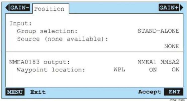
Groupselection: This parameter allows you to connect the PI44 to a group of SimNet instruments. If such a group is not present, the parameter is unavailable, and fixed to STAND-ALONE. This mean that you can manually select data source from third-party units.
Source:ThePI44willautomaticallyreadtheNMEAinputsto searchforavailablesources.Ifnosourcesarefound,thephrase “(noneavailable)”isgiven.Ifoneormoresourcesarefound youmaychoosebetweenthem.
Waypointlocation: Using this parameters, you can setup the PI44toexport navigational waypoints as WPL telegramson NMEA1 and/or NMEA2. A waypoint is automatically generated every time you press the EVENT button.
Navigation
The Interfacesetup/Navigationwindowallowsyoutodefine asourceforpositioninformation.Italsoallowsyoutosetup exportofnavigationalwaypoints.

Groupselection: This parameter allows you to connect the PI44 to a group of SimNet instruments. If such a group is not present, the parameter is unavailable, and fixed to STAND-ALONE. This mean that you can manually select data source from third-party units.
Source:ThePI44willautomaticallyreadtheNMEAinputsto searchforavailablesources.Ifnosourcesarefound, thephrase (noneavailable)isgiven.Ifoneormoresourcesarefoundyou maychoosebetweenthem.
Navigation
The Interfacesetup/Waterwindowallowsyoutodefinesourcesforwaterrelatedinformation.Italsoallowsyoutosetupexportofwaterrelatedinformationtelegrams.

(CD11103U)
Waterdepthinput: The PI44 is here configured to either supply its own water depth information, ortoreceivethat information from an external source.
Groupselection(Waterdepthinput): This parameter allows you to connect the PI44 to a group of SimNet instruments. If such a group is not present, the parameter is unavailable, and fixed to STAND-ALONE. This mean that you can manually select data source from third-party units.
Source(Waterdepthinput):ThePI44willautomaticallyread theNMEAinputstosearchforavailablewaterdepthsources. If nosourcesarefound, thephrase“(noneavailable)”isgiven. If oneormoresourcesarefoundyoumaychoosebetween them. Intheexampleabove, theinternalechosounderistheonly sourceavailable.
Watertemperatureinput:ThePI44ishereconfiguredto eithersupplyitsownwatertemperatureinformation,orto receivethatinformationfromanexternalsource.
Groupselection(Watertemperatureinput):Thisparameter allowsyoutoconnectthePI44toagroupofSimNet instruments. If such a group is not present, the parameter is unavailable, and fixed to STAND-ALONE. This mean that you can manually select data source from third-party units.
Source(Watertemperatureinput): The PI44 will automatically read the NMEA input to search for available watertemperature sources. If nosources are found, the phrase “(none available)” is given. If oneormoresources are found you may choose between them. In the example above, the internalechosounder transduceristheonlysource available.
Watertemperatureoffset: This function allows you to enter an offset value for the temperaturesensor.
Waterspeedinput:ThePI44ishereconfiguredtoreceive waterspeedinformationfromanexternalsource.
Groupselection(Waterspeedinput): This parameter allows you to connect the PI44 to a group of SimNet instruments. If such a group is not present, the parameter is unavailable, and fixed to STAND-ALONE. This mean that you can manually select data source from third-party units.
Source(Waterspeedinput):ThePI44willautomaticallyread theNMEAinputstosearchforavailablewaterspeedsources. If nosourcesarefound, thephrase“(noneavailable)”isgiven. If oneormoresourcesarefoundyoumaychoosebetween them. Intheexampleabove, nosourceshavebeenfound. Tocorrect this, youmustsetupyourspeedlogtoprovidethecurrentspeed onNMEAformat, andconnectaserialcabletothePI44 operatorstation.
LOGspeedcal(ibration): The PI44 is preset to receive 19.000 pulses per nautical mile from a paddle wheels speed log. However, this figure may need to be compensated for known variances or if an others speed logs is used. The pulserate is calculated by the following equation:
(19.000xIndicatedspeed)dividedby(ActualspeedfromGPS)
NMEA0183Output:Selectanyofthetelegramformats providedbelow,andswitchthemonorofforoutputonthe NMEA1orNMEA2seriallines.Notethattheinformationcan onlybeexportedifthePI44caninfactprovidetheinformation.
Identification
The Interfacesetup/Identificationwindowallowsyouto defineidentificationdataforthesystem.
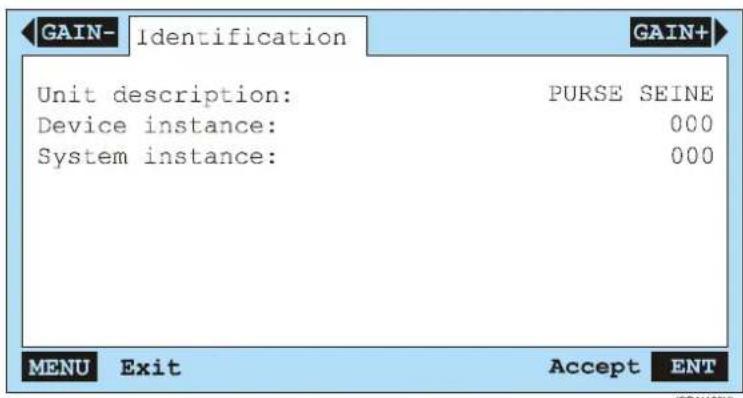
Unitdescription: Enteranynameorphrasethatyouwishto identifythePI44with.Typicalphrasesare“Purseseine”, “Trawlmonitoring”etc.
Deviceinstance: ThisparameterisonlyusedifyourPI44is connectedtoaSimNetnetwork.Ifthisisthecase,youmust provideauniquedevicenumber.
Systeminstance:ThisparameterisonlyusedifyourPI44is connectedtoaSimNetnetwork.Ifthisisthecase,youmust provideauniquedevicenumber.
Applicable telegram formats
The following NMEA telegram formats are used by the PI44.
APB = Autopilot Sentence "B". The information provided includes Status, Crosstrackerormagnitude, Directiontosteer, Crosstrackunits, Bearingorigintodestination, Destination waypointidentification, Bearing, and Headingtosteer.
DBK = Depth below keel. The information provided includes the depthin meters, fathomsand feet.
DBS = Depth below surface. The information provided includes the depth in meters, fathoms and feet.
DPT = Heading - Deviation & Variation. The information provided include the depth and the offset from the transducer.
GGA = Global positioning system fix data. The information provided includes Universaltimecoordinated, Latitude, Longitude, GPSqualityindicator, Numberofsatellitesinview, Horizontaldilutionofprecision, Antennaaltitude, Geoidal separation, AgeofthedifferentialGPSdata, and Differential referencestation.
GLL = Geographic Position - Latitude/Longitude. The information provided includes Latitude, Longitude and Universaltimecoordinated.
MTW = Water temperature. The information provided includes watertemperature in Celsius.
RMA = Recommended minimum navigation information. The information provided includes Blinkwarning, Latitude, Longitude, Timedifference, Speedoverground, Trackmade good, and Magnetic variation.
RMB = Recommended minimum navigation information. The information provided includes Status, Crosstrackerror, Direction to steertowaypoint, Destination waypoint latitude and longitude, Rangetodestination (in nautical miles), Bearing to destination (in degrees True), and Destination closing velocity (inknots).
RMC = Recommended minimum navigation information. The information provided includes Universaltimecoordinated, Latitude, Longitude, Speedoverground(inknots), Trackmade good, degreestrue, Date, and Magnetic Variation.
VHW = Water speed and heading. The information provided includes Vesselspeedrelativetothewater(inknotsand kilometersperhour)andHeading(trueandmagnetic).
VTG = Track made good and Ground speed. The information provided includes Trackdegrees(trueandmagnetic)andSpeed(inknotsandkilometersperhour).
XTE = Cross-Track Error, Measured. The information provided includes Status, CrosstrackerrorandDirectiontosteer.
Marker line setup
ThesesettingsareusedtosetupthePI44parametersrelatedto themarkerlinesonthegraphicdisplay.Whenenabled,these markerlineswillbesuperimposedonthegraphicdisplay.
Toaccesstheparameters, presstheADJbuttonwhenyouhave agraphicdisplayintheactivewindow. Then, presstheGAIN+ buttontwotimesuntilthesettingsappear. Youcanalsopressthe MENU button to access the Echo quick menu, select Graphic setup (8), and then press the GAIN+ button until the setup dialogueappears.

TheMarkerlinesetupcontrolshowthemarkersfromtheapplicablesensorsaredisplayedontheGraphicdisplay.Thesetupfunctionwillreadthecurrentsensorconfiguration,andlisttherelevantsensorsonthemenu.
In the example provided, the PI44 is setup with two depth sensors, one height sensor, as well as input from surface temperature feeler. These will all provide information to the graphic display. Those sensor that will not provide presentable information will not be listed.
Note:
The Catch and Bottom Contact sensors will not be able to provide information for such markers, astheyonlytrigger on/off.
Auto: This option allows you to enable and set the delay automatically calculated by the Trawl calculator. Select On to enable the function. The current delay is then shown with grey characters, and the values cannot be edited. If you select Off you must enter the Delay values manually. Note that the Trawl calculator must be enabled to provide the delay information. If such information is unavailable, the On/Off choice is shown with grey characters.
Delay: Foreachsensormarker, you can define a presentation delay. The echogram information provided by the PI44 is from directly below the hull, but the marker information comes from the sensors, which are positioned and distance away. You can therefore calculate an additional delay (in minutes and seconds) manually based on the wire length, towing depth and speed, and with this delay place them as a marker at its correct location on the echogram. You can also enable the Trawl calculator function, and have the delay calculated automatically.
Width: Foreachsensormarker, you can definethewidth of the markerline in pixels. The colour of the line will automatically be set to the current background colour of the numeric presentation of the sensor data. The default linewidth this 2 pixels.
Show: Switchthemarker(s)onorofftosuityourpreferences andneedforinformation. Usethepalettetodefineunique coloursinordertodistingushthemarkersfromeachother.
Surfacetemperature: This parameter allows youto superimpose atemperature curve on the graphic display. Toread the values, you need to enable the temperature scale in the Graphic setup. You can change the width of the temperature markerline, and choose a colour from the palette.
Sensormarkerinexpansion: With this setting active, the Depth and Height marker lines are expanded, and thus easiest to read. This is useful feature when the sensoristowed closeto the bottom, and its particular important for the Heights sensor.
Markerwhitezone: When enabled, whitepixels are added above and under themarkertomakeiteasiertodistinguishit from the background colours.
Heightmarkerinmainechogram: If you have a Height sensor on the top of bottom trawland the trawlopening is small, it may be difficult to tell the Height marker from the bottom echo. If this is the case, set this function to Off, and view the Height marker in expanded mode only.
Heightreference:TheHeightsensormeasuresthedistance fromtheheadropetothebottom.IfyouusethePI44echo sounder, set Height reference to Bottom (default), and the heightmarkerwillfollowthebottomcontour.Ifyoueven definethedelaycorrectly,youwillbeabletoseethetrawlin truemotion.Ifyoudonothaveenactiveechosounder,set
Height reference to Surface. The height will then be shown with 0mdepthasreference, and themarkerlinewillappearasa nearly straightlinesomedistance below 0 meters. Thedistance from the 0 meterline and downtothemarkerlinewill bethe currentopeningofthetrawl.
Related topics
→ Graphicdisplay, page41
→ Graphicsetup,page184
→ Trawlcalculator, page221
Navigation setup
TwoNavigationsetupdialoguesmaybeaccessed:
• From the Highway display presentation
- FromtheSetupmenu
Inbothcases, settingsareprovidedtosetupthePI44 parametersrelatedtothenavigationdisplaypresentation. The parametersdefinedfortheHighwaypresentationarespecific forthatpresentationonly.TheNavigationsetupchoiceonthe Setup opens the Pilot/Position setup dialogue with parameters validfortheentirePI44operation.
Highwaydisplaypresentationparameters
To access the parameters, press the ADJ (Adjust) or ENT buttonwhenyouhavethenavigationdisplay("Highway")inan activewindow.
Navigation setup:
XTE distance:
00.10nm
XTEdistance:DefinehowlargecrosstrackerrorthePI44can acceptbeforethealarmistriggered.
Pilot/ Positionsetup
ThesesettingsareusedtosetupthePI44parametersrelatedto thenavigationdisplaypresentations.Toaccesstheparameters, presstheMENUbuttonontoopenthemainmenu.Selectthe Setup menu (4) and then Pilot/Position Setup (1).

Displaypositionas: Select how you wish the position datato bedisplayed; LAT/LON (Latitude/Longitude), LORAN Cor DECCA.
Displayspeedas: Selecthowyouwishthespeedinformationto bedisplayed; SOG(speedoverground)orSTW(speedthrough water).
Courseandbearingas: Selecthowyouwishthecourseand bearinginformationtobedisplayed;TRUEorMAGNETIC reading.
TimeandDate:Settheinternalclock.
Related topics
→ Highwaydisplay, page53
Numeric setup
ThesesettingsareusedtosetupthePI44parametersrelatedto theNumericdisplay.
TheNumericdisplayshowsthedatafromthesensorsintheir rectangularalphanumericalpresentations. Thedigitsinthe alphanumericalpresentationsareblackwhenthedataarevalid, theyaregreywhenthevaluesareonlypredicted, ortheyare replacedwithasterixcharacters(*)whenthecontactwiththe sensorislost. Theyellowpulselampislittoindicateeverytime informationinreceivedbackfromthesensor. Thepositioningof thealphanumericalpresentationsiscontrolledbytheorderof whichthesensorswereconfiguredintheSensorsetup dialogue.
To access the parameters, press the ADJ (Adjust) or ENT buttonwhenyouhavethenumericpresentationsinanactive window.

Showgraphicalarm: Thegraphicalarmisthesmallred triangleineachsensorpresentation. If the triangle is lit, it indicates an alarmsituation. If the triangle points upwards a "minimum" alarm has been triggerd, if it points downwards, a "maximum" alarm has been triggerd. The default setting for this parameter is ALWAYS.
Sensor timer: The Catch and Bottom Contact sensors have a timerfeatureindicatinghowmanytimeseachsensorhasbeen activatedduringatow. Thetimerrunwhenthesensoris activated, and stopsoncethesensorisreleased. This parameter allowsyoutoenableordisablethesetimers. Thedefaultsetting isON. YoucanalsoaccessthisparameterintheGraphicsetup.
Reset sensor timers: The Catch and Bottom Contact sensors haveatimerfeatureindicatinghowmanytimeseachsensorhas beenactivatedduringatow.Toresetthetimersto0priortoa newtow,selectYES.DefaultsettingisNO.Youcanalsoaccess thisparameterintheGraphicsetup.
Related topics
→ Howtodefinesensorpresentations, page56
→ Numericdisplay,page33
Offset adjust
ThesesettingsareusedtosetupoffsetvaluesfortheDepthandSpreadsensors.
Toaccesstheparameters, presstheMENUbuttonontoopenthe main menu. Then, open the Setup menu (4) and select Sensor alarm/calibration(4). Whenthedialogueopens, pressthe GAIN+ button four times to open the Offset adjust dialogue.

Whenaccessed, this dialogue will only display the Depth and Spread sensors currently configured. Offset adjustments can be only bemade on the listed sensors. Enter anegative or positive valuetodecrease or increase all readings from the chosen sensor.
Related topics
→ Howtodefinesensoroffsets,page66
→ PIDepthsensor,page124
→ PSDepthsensor,page129
→ PISpreadsensor,page143
Page setup
ThesesettingsareusedtosetupthePI44parametersrelatedto thepage;automaticpagerotationandmenulanguage.
Toaccesstheparameters, presstheMENUbuttonontoaccessthe main menu. Then, open the Setup menu (4) and select Speed alarm, units&language(2).
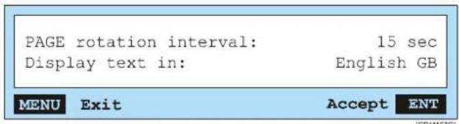
PAGE rotation interval: If you press the PAGE button and holdsitdepressedforminimumthreeseconds,youwillstart automaticpagerotation. ThefeaturewillmakethePI44leaf throughitsfourpagesautomatically. Therotationintervalisthe timeitkeepseachpagedisplayedbeforeitbringsupthenext page.Toswitchthisfunctionoff,pressanyotherbuttononthe keypad.
Displaytextin: This parameter allows you to change the language. Not that the presence of other language is the will depend on the software version.
Related topics
→ Howtocontrolautomaticpagerotation,page100
Palette setup
ThesesettingsareusedtosetupthePI44parametersrelatedto presentationcolours.
The information provided by the PI44 can be presented using one outoften palettes. In each palette, the text and background colours are defined. Four of the palettes are user defined, and you can make your own preferences.
To access the Palette setup, press the Menu key, and select Setup (4). On the submenu, select Palette setup (7).
To leaf through the palette pages, use the + and - buttons. To changecoloursettings, usetheSelectorpadto findthegraphic element, and the + and - buttonstoleafthroughthe available colours.
- Palettes1through4arefactorydefaults,thesecannotbe changed.
- Palettes5through8aresetupbySimrad, butyouarefreeto changethemtosuityourpreferences.
- Palette9isspare.
Position display setup
ThesesettingsareusedtosetupthePI44parametersrelatedto thepositiondisplaypresentation.
To access the parameters, press the ADJ (Adjust) or ENT buttonwhenyouhavethePositiondisplayinanactivewindow.
Pos display setup:
| Log 1: | 00000.0 nm |
| Log 2: | 00000.0 nm |
Log1/2:Usethisparametertoresetthetwodistancelogs.
Related topics
→ Positiondisplay,page54
Quick guide
This function provides you key information about PI44 operation.
To access the quick guide, press the Menu key, and select Setup (4).Onthesubmenu,selectQuickguide(9).Youcanalso accessthequickguidefromthestart-upscreen.Onceaccessed, youcanleafthroughthepagesusingtheGAIN+andGAIN-buttons.
Receiver setup
Thesesettingsareusedtoestablishthecommunication parametersbetweenthePI44andthesensors.
Toaccesstheparameters, presstheMENUbuttonontoaccessthe Setup menu (4). Then, select Receiver setup (6). You need to acknowledge the access with the ENT button before the dialogue is displayed.

TheReceiversetupparametershaveamajorinfluenceonthe PI44performance. Thedefaultsettingsarethosewehavefound tobethebestforgeneraluse,butforindividualinstallations optimizedsettingsmayenhancetheperformance.
Interferencefilter: Whenthisfilterisactiveitwillremove interference(noiseandfalseechoes)fromotherechosounders andsonarsinthethevincinityofyourownvessel.Itmaynot removeallinterference,butinmostcasesyouwillfindthis filtertobeveryefficient.Ifyousufferfrompoorrange performance, and the spectrum on the Status Display is nearly flat,thisfiltermayalsoproveuseful.Anormalsensorwillthen showupwithanarrowpeakatitsdedicatedfrequency.This filterisbydefaultswitchedonandsettolevel9,andwilltend toprioritizestrongersignals.
Interferencefilterlevel:Usethissettingtocontrolthestrength of the Interference filter. 9 is the default value and the heaviest filtering.Selecting0willhardlyhaveanyeffect,andisreally equivalentwiththefilterswitchedoff.
Sensorfilter:ThePI44isdesignedtoquicklyupdatedata. Afterthesensorshavebeensubmerged,thereceiverrequires onlythreeconsecutivepingsfromindividualsensorstocalculate anddisplaytheirrespectiveinformation.However,ifyou experienceproblemswiththereception,youmayalsotrythis filter:itwillaveragethedatareceivedfromthesensors.Light filteringwillaveragethedatareceivedbythelastfourpings, whileheavyfilteringaveragesthedatareceivedbythelasteight pings.Werecommendthatyouonlyuseheavyfilteringifthere arelargefluctuationsinthedisplayeddata,orifterateof changeissmall.Reducedfilteringshortensthedelaybetween updatingthechangesinsensorlocationandthecorresponding displayedinformation.DefaultsettingisLIGHT.
Catch/BottomSensorfilter: This filter is used to smooth out the information from the Catch and Bottom Contact sensors. When the filter is switched off any change in sensor status will immediately be shown on the display. Set to LIGHT the change in status must last and remain stable for least twopings before the display is changed. When HEAVY filtering is applied the change in status must last and remain stable for least four pings before the change is shown on the PI44 display.
AGC(AutomaticGainControl): This function allows the PI44 to automatically control there receive vergain. The units read and interpret these received signal strength, and adjust the gain accordingly. During normal operation, ONisthere recommended (and default) setting.
Manualgain: If you decide to switch the AG Coff you must set the gain manually. This can be useful when you work at maximum detection ranges with favourable noise levels. The default setting is 0dB, and you can adjust the gain in steps of 20dB.
Multipathfilter(MPfilter): When you operate in an areas with substantial reverberation duetobottom topography, or in shallow waters, you may experience problems when consecutive operating channels have been configured, but the corresponding sensors are not in use. False signals and sporadic error values can also be caused by other types of hydroacoustic equipment operating on the PI44 frequency range. This filter has been implemented to remedy for such interference problem. Default setting is OFF.
Multipathfilterlevel(MPfilterlevel): WhentheMultipath filterhasbeenenabled, you can adjust the filter level in small step to correct the interference problem. Lower filter values represent stronger filtering. It is best to experiment with this parameter by reducing the value in step of 3dB until the
detectionerrordisappears. Checkthatthesignalsfromthe sensorinusearestillbeingreceived,iftheyarenot,thefilter willnotbeofhelpinthisparticularsituation.Thefilter's effectivenessisbothlocationandnetspecific.Therefore,the sameparameterswillnotnecessaryworkindifferentareasor usingvarioustypesofnets.Defaultsettingis42dB.
DetectionThreshold(DT): This function will inhibit reception of the weakest signals. If you experience problems with interferences, signal generating fals data and all of the configured sensors are operative (analogous with the Multipath problem); increase the Detection Threshold value carefully in step of 1 dB. High values allow only strong sensors signal to be detected. Alower threshold value will provide greater range if conditions are optimal, but if toolow, interference will be detected. It is best to experiment with different value to determine which to employ.
Note: If the Detection Threshold (DT) value is set higher than 28 dB, all signals will be prevented from being detected.
Maxshootingspeed:ThePI44hasabuiltindoppler compensationfunctionwhichisconfiguredusingthisparameter. Theparameterandrelatedfunctionishoweveronlyrelevantif sensordataisdesiredwhilethepurseseineisbeingdeployed.It hasnoeffectoncethevesselisstoppedwaitingforthenetto sink.Notethatifyousetthisparametertohigh,youcancreate aconflictwiththechannelselection.Shouldthissituationarise, thefollowingmessagewillappear:Maxshootingspeeddiffers fromwanted,channelsaresettooclosetoeachother.
Sensor alarms
ThesesettingsareusedtosetupthePI44parametersrelatedto sensoralarms.
Toaccesstheparameters, presstheMENUbuttonontoopenthe main menu. Then, open the Setup menu, and select Sensor alarm/calibration.
Each sensor has an individual alarm setting, and you can also trigger alarm to warn you about sudden temperature changes and shallow water. Whenever an alarm is triggered a audible signal is provided, and a message on the display presents the cause of the alarm. Unless there are on the alarm is corrected, or the alarm disabled, it will sound again after 20 seconds.
DuetotheamountofchoicesavailableforthePI44,thealarm parametersareorganizedinthreedialogues.
- Sensor alarm: This dialogue allows you to defined alarms related to the information provided by the sensors.
- Surfacetemperature: This dialogue allows you to setup alarmstowarn you about surfacetemperatures, and to indicate sudden temperature changes.
- Clearance: This dialogue allows you to define alarms to monitorifatrawlortowedobjectcomestoocloseortoofar offthebottom.
The Sensor alarm/calibration choice on the Setup menu also allows youtodefineparametersfordepthcalibrationandoffset. Theseareexplainedseparately.
Topics
→ Sensoralarms, page212
→ Surfacetemperaturealarms, page213
→ Clearancealarm,page214
Related topics
→ Depthcalibration,page176
→ Offsetadjust,page203
→ Depthalarmsetup,page180
→ Fishalarmsetup,page180
Sensoralarms
This dialogue allows you to define alarms related to the information provided by the sensors you have in current use on your PI44 system. The appearance of the dialogue will thus automatically chan get out your individual configuration.

[CD11103W A]
Eachsensorhasanindividualalarmsetting.Toenablealarm, youmustdefineminimumandmaximumlimitsforthesensor, andsetittoON.Ifthealarmistriggered,anaudiblesignalwill beprovided,andamessagewilltellyouwhichsensorthat causedthealarm.Onceanalarmhasbeentriggered,itis automaticallydisabledfor20seconds.Afterthistimeitmaybe triggeredagainunlessthealarmsituationhasbeenrectified,or youhavedisabledthealarm.
The Bottom Contact and Catch sensors can only provide alarmswhentheyareactivated.
Related topics
→ Howtodefinealarmlimits,page96
Surfacetemperaturealarms
This dialogue allows y out o define alarms related to the surface temperature. Inorderto enable these alarms, yoursystem must have relevant sensors fitted.

Thesurfacetemperaturesensorhasindividualalarmsettingsfor maximumandminimumtemperature.Toenablealarm,you mustdefinetheappropriatelimits,andsetittoON.Ifthealarm istriggeredanaudiblesignalwillbeprovided,andamessage willtellyouthatthesurfacetemperaturealarmwassetoff. Onceanalarmhasbeentriggered,itisautomaticallydisabled for20seconds.Afterthistimeitmaybetriggeredagainunless thealarmsituationhasbeenrectified,oryouhavedisabledthe alarm.TheShearalarmwillbetriggeredifthetemperature changesfasterperminutethanthevalueyouhaveentered.
Alarmmaximum/minimum: Toenablethetemperature alarms, selectupperandlowerlimits, andthenswitchOn.
Shearalarm: This alarm triggers if the temperature changes faster per minute than the limit value provided.
Related topics
→ Howtodefinealarmlimits,page97
Clearancealarms
Thesealarmswillnotifyyouifatrawlortowedobjectcomesto closeorfaroffthebottom.

The Clearancepre-warningalarmsareusedtowarnyouifa trawloranothertowedobjecteithermovestooclosetothe bottom,orliftstoofaroffthebottom. Youmusthavetheecho sounderswitchedontousethisalarm.Toenableit,setthe minimumlimittotheminimumalloweddistancebetween the footropeandthebottom,and/orthemaximumlimittothe maximumalloweddistancebetween thefootropeandthe bottom.Then,switchoneorbothalarmstoON.Thealarmis triggeredifthereadingfromaDepthsensormountedonthe footrope(oramanualdepthmarker)exceedsoneofthedefined limits.Tousethisalarmforasingletowedobject,selectthe Depth sensor as a Foot rope sensor in the Trawl info dialogue.
Clearancepre-warning,min:Setminimumalarmlimit,and selectONwhenyouwishtoenablethealarm.
Clearancepre-warning,max:Setmaximumalarmlimit,and selectONwhenyouwishtoenablethealarm.
Related topics
→ Howtodefinealarmlimits,page97
→ Trawlinfodialogue,page223
Sensor setup
Theseparametersareusedtoestablishcommunicationbetween thePI44andthesensors.
Toaccesstheparameters, press the MENU button to open the main menu, Then select Sensor setup on the Setup menu.
Note: Inordertosetuptheseparameterscorrectly,youneedtoknow whatkindofsensorsyouhave,howoftentheprovide informationupdates,andonwhichchannelstheycommunicate. Aformhasbeenprovidedinthefrontofthisbooktowritedown thisinformation.
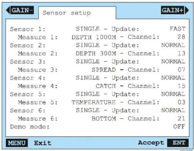
Foreachofthesensors, enableit, and selectsensortype, communicationrate and communicationchannel.
Sensor: Choose Single to enable the sensor, or None to disable it.
Measure: Choosethesensortype.
Update: Select Normal, Fast or Slow. This is the time elapsed between each information update from the sensor. The setting you choose her most match with the setting defined in the applicable sensor.
Channel: Select any channel between 0 and 30, or No (none). Thesettingyouchooseheremust matchwiththesettingdefined intheapplicablesensor.
Demo mode: Set to Off to enable normal operation using sensorsandechosoundertransducer.
If you configure less thens six sensors, you will be able to set the Sensor parameter to Dual. You can not use this setting. Dual sensors are not yet available, and this functionality is not yet supported by the digital signal processing in the PI44. The ability to choose Dual is implemented for future expansion only, and any attempt to choose this setting will not work.
Note: Thesettingsyouchooseforupdaterateandcommunication channelmustbeidenticaltothesettingsintherelevantsensor.If thesesettingsarenotmatched,yourPI44willnotbeableto readtheinformationfromthesensor!
Related topics
→ Howtosetupthesensors, page58
Speed setup
ThesesettingsareusedtosetupthePI44parametersrelatedto speed.
Toaccesstheparameters, presstheMENUbuttonontoaccessthe mainmenu. Then, selectSpeedalarm, units&languageon theSetupmenu.
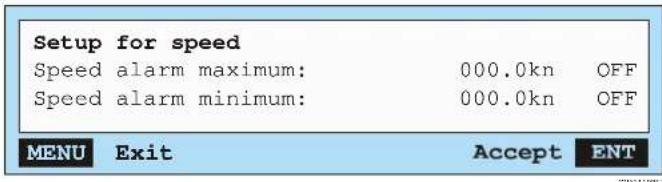
Speedalarmmaximum: This parameter provides you with an audible warning if the vessel's speed exceeds a predefined speed limit.
Speedalarmminimum: This parameter provides you with an audible warning if the vessel's speed is slower than a predefined minimum.
Related topics
→ Alarmprocedures,page96
Status setup
ThesesettingsareusedtosetupthePI44parametersrelatedto theStatusdisplay.
To access the parameters, press the ADJ (Adjust) or ENT buttonwhenyouhavetheStatusdisplayintheactivewindow.
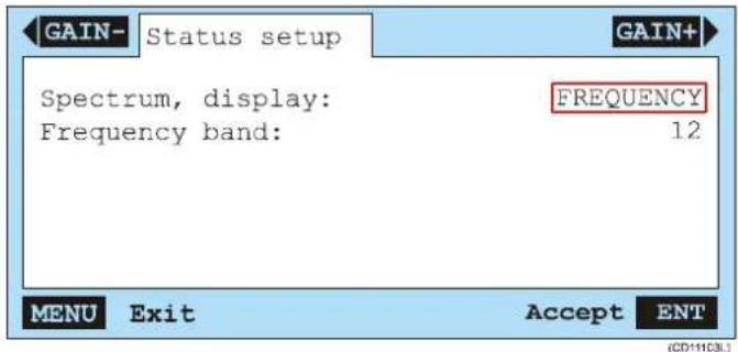
Spectrum, display: Use this parameter to select Frequency or Channel in the left hand graph in the Status display. When Channelisselected, each comminication channel is shown with ablackbar.
Frequency band: The graph in the Status display is not wide enough to show allentire frequency bandwidth sufficient resolution. For this reason, you can select which frequency band you wish to see. Select any value between 00 and 15. Selecting 00 provides the full bandwidth. Each band (except 00) covers between 800 and 1000 Hz with some overlap, and there are shown in the table below.
| BandFrom (kHz) | To (kHz) | BandFrom (kHz) | To (kHz) |
| 0043,250.40846,347,3 | |||
| 0143,244,10946,847,7 | |||
| 0243,744,61047,348,2 | |||
| 0344,145,01147,748,6 | |||
| 0444,645,51248,249,1 | |||
| 0545,045,91348,649,5 | |||
| 0645,546,31449,150,0 | |||
| 0745,946,81549,550,4 |
Related topics
→ Statusdisplay, page46
Surface temperature setup
ThesesettingsareusedtosetupthePI44presentation parametersrelatedtothesurfacetemperaturepresentation.
To access the parameters, press the ADJ (Adjust) or ENT buttonswhenyouhaveaSurfacetemperaturedisplayinthe activewindow.

(CD1103Q)
Temperaturescalemax/min:Usethesesettingstodefinethe maximumandminimumvaluesinyourtemperaturescale.
Temperaturegrid: When enabled, this function places horizontal gridlines in the temperature graph to make it easier to read the data.
Temperatureoffset: Using this function, you can add or subtract a fixed temperature value for compensate for known deviations in the sensor.
Averageoftemperaturereadings: If you wishtoread the avergatemperature, you must define how many readingstotake before theresultiscomputed.
Related topics
→ Surfacetemperaturedisplay,page45
Temperature setup
ThesesettingsareusedtosetupthePI44parametersrelatedto the temperature representationonthegraphicdisplay. When enabled, atemperaturescale will be placed on the graphic display.
Additionally, atemperatureline can be superimposed on the graphic display. This feature is enabled in the Markerline setup.
Toaccesstheparameters, presstheADJ(Adjust)buttonwhen youhaveagraphicdisplayintheactivewindow. Then, pressthe GAIN+buttonuntilthesettingsappear. Youcanalsopressthe MENU button to access the Echo quick menu, and then select Graphicsetup(8).
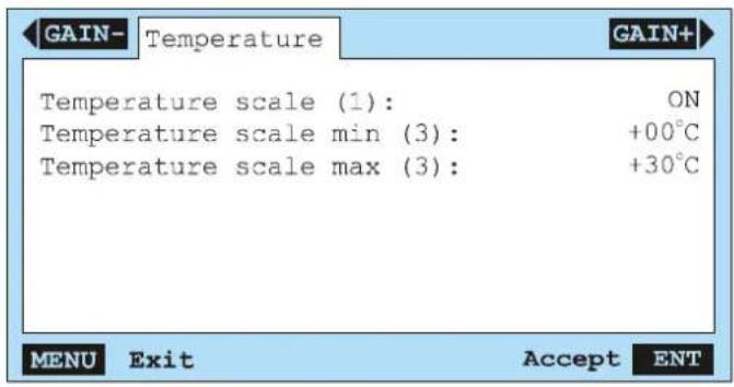
Temperaturescale: Thisselectionswitchesthetemperature scaleonoroff.
Temperaturescalemin/max: Thesetwosettingsdefinethe maximumorminimumtemperaturesonthescale.
Related topics
→ Markerlinesetup,page197
→ Graphicdisplay,page41
→ Graphicsetup,page184
Trawl calculator
ThesesettingsareusedtosetupthePI44parametersrelatedto theTrawlcalculator.
Toaccesstheparameters, press the ADJ button when you have agraphic display in the active window. Then, press the GAIN+ button four times until these settings appear. You can also press the MENU button to access the Echo quick menu, select Graphic setup (8), and then press the GAIN+ button four times.

Purpose
The Trawlcalculatorisusedwhenyouhavechosento superimposesensordataontotheGraphicdisplay.However,in ordertopositionthesensormarkercorrectlyontheechogram, youneedtocalculatethedelay.Thisisbecausetheechosounder informationisprovidedbyatransducerlocatedunderthevessel, whilethesensorsarelocatedonthegear,whichmaybe positionedseveralhundredmetersbehindthevessel.Toadjust forthisdelay,youmustcalculatethevalue(inminutes)based onthevessel'sspeed,thewirelengthandthedepthofthegear. YoucandoitmanuallyandenteraMarkerlinedelayinthe Markerlinesetupdialogue,oryoucanleavethecalculationto theTrawlcalculator.
For a complete procedure, referto the Operational procedures chapter.
Parameters
Trawl calculator mode: Select Auto or Manual. When SelectingAutoallowsyoutoretrieveorentertrawldata, and thePI44willperformthecalculation.SelectingManual switchestheTrawlcalculatoroff.
Towing speed: Select Manual to enter the average vessel speed, or AutotoallowthePI44toretrievetheinformation automatically. If you select Autoyou can choose to read the speed over ground (SPG) or the speed through water (STW).
Note: Inordertoretrievespeedinformation, therelevant equipment (GPS) must be interfaced to your PI44.
WhenyoureadthespeedinformationfromaGPS,the informationisveryaccurate.Duetothefactthatthetrawl calculationsaremadecontinuously,eventheslightestchangein speedwillbereflectedonthedisplaypresentation,andyoumay experience thatthemarkersfluctuate.Ifthisisaproblem,enter theaveragevesselspeedmanually.
Trawl depth: Select Manual to enter average trawl depth. If yourunapelagictrawl,youmustusethissetting.Select Bottomifyourunabottomtrawl,andyouexpectthetrawl depthtobeequaltothedepthmeasuredbythechosounder. Notethatinordertoupdatethecalculatorautomatically,the echosoundermustbeoperationalprovidingvaliddepthdata. Theseareshownwithgreycharacters.
Wirelength: Enterthelengthofthetrawlwire. Inmost cases, this is thelength from the stern of the vessel to the trawldoors.
Wirelengthoffset: Enterthedistancefromthetrawldoorsto theheadrope. Thisisnormallyafixedvalue. Thecalculatorwill addthewirelenghtothewirelengthoffset, andusethesumof theseinthecalculations.
Calculated marker delay: When in Auto mode, the delay is shown in minutes and seconds.
Related topics
→ Howtosetupmarkerlines,page81
→ Markerlinesetup,page197
Trawl info setup
ThesesettingsareusedtosetupthePI44parametersrelatedto thetrawlpresentationsontheGraphicdisplay.Whenenabled, markerlinesprovidingtrawldepthinformationwillbe superimposedonthedisplay.
ThemarkerlinesareenabledintheMarkerlinesetup.
Toaccesstheparameters, presstheADJ(Adjust)buttonwhen youhaveaGraphicdisplayintheactivewindow. Then, press theGAIN+buttonuntiltheparametersappear. Youcanalso press the MENU button to access the Echo quick menu, and thenselectGraphicsetup(8).
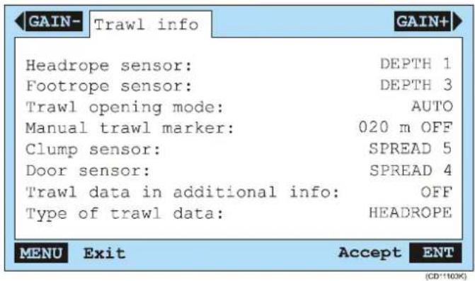
Headropesensor: Thissettingdefineswhichsensorthatis placedontheheadrope.
Footropesensor: This setting defines which sensor that is placed on the footrope.
Trawlopeningmode: Thisparameterdecideshowthetrawl opening shall be recreated on the Graphic Display. If you have sufficientsensorsonthetrawlyoumustselectAuto, and the PI44willautomaticallycalculatethetrawlopeninganddrawit accordingly. If you only have onesensoronthetrawlopening (DepthorHeightsensorontheheadrope), the Manualsetting will add an artificial line on the Graphic Display. The distance from the headropeto the footropemust then be defined manually using the Manualtrawlmarkerparameter (below).
Manualtrawlmarker:Setthemanualtrawlopeningheightfor usewiththeTrawlopeningmodeparameter(above).
Clumpsensor: Thissettingdefineswhichsensorthatisplaced ontheclump.
Doorsensor: This setting defines which sensor that is placed on the door.
Trawldatainadditionalinfo:Whenenabled,thecurrenttrawl depthwillbeaddedtotheAdditionalinformationlineinthe GraphicDisplay.
Typeoftrawldata: This parameter defines which information that is provided in the Additional information bar on the GraphicDisplay.
Related topics
→ Markerlinesetup,page197
→ Graphicdisplay,page41
→ Graphicsetup,page184
Units setup
ThesesettingsareusedtosetupthePI44parametersrelatedto units.
Toaccesstheparameters, presstheMENUbuttonontoaccessthe mainmenu. Then, selectSpeedalarm, units&languageon theSetupmenu.

Selecttheunitsyouwishtouseonthevariousdata. These parametersareselfexplanatory.
PI CONFIGURATOR
Purpose
The purpose of the PI Configurator utility is to be able to configuresensorssothattheycanoperateondifferent communicationchannels.SeveralPIequippedvesselsmaythen operatesimultaneouslyinthesameareawithoutinterference.
Theutilityalsoallowsyoutochangetheupdaterateoneach sensor. Thisisthetimeelapsedbetweeneachdatatransmission fromthesensortothehostPIsystem.
Thisdocumentdescribessoftwareversion3.40.
Introduction
→ Basicinformation,page227
→ Aboutsensorconfiguration,page229
→ Maindialoguedescription, page231
Procedures
→ Howtoperformsoftwareinstallation,page234
→ Howtointerfaceesensor, page235
→ Howtoperformbasicsensorconfiguration, page236
→ HowtosetupaTwinSpreadsystem,page237
→ Howtuploadfactorysettings, page239
Reference information
→ References, page240
Maintenance
→ Programmingmodes,page262
→ Makingaprogrammingcable, page263
→ Troubleshooting, page264
Sensor test procedures
→ Sensortestprocedures, page265
Basic information
Defaultsensorsettings
PIandPSsensorsaredeliveredfromSimradconfiguredwith commondefaultsettings.Whenrequired,theindividualsensors maybere-configuredwithregardto:
- Communicationchannel
- LEDcontrol
- Pingcontrol
- DataUpdaterate
- Remote
• ShowchannelwithLEDflashatstartup
WhocanconfigurePI sensors?
Sensorconfigurationisnormallyperformedbyauthorized Simradtechnicians. However, individualswithbasiccomputer skillsandaccesstothenecessaryequipmentshouldnotfindit difficult.
Programmingmodes
ThePIConfiguratorconfigurationsoftwarehastwo programming modes, Standard and Professional.
Note: ItishighlyrecommendedthattheconfigurationofPIandPS sensorsintheProfessionalmodeisonlyperformedbyskilled andexperiencedpersonnel.
Necessaryequipment
The following hard-and software is required to set the PI Configurator utility:
• PICoufigurationsoftware
- A PC with Microsoft Windows© 2000 or XP operating systemandaCOMport(serialline).
- Asensorprogrammingcableforeitherastationaryor portablePC.
The sensor programming cables for stationary and portable PCs are constructed differently and are not ____ interchangeable.
Available equipment
The following is available from Simrad:
• UserGuide(857-164924)
• Software(889-204037)
• ProgrammingcableforstationaryPCs(380-204624)
• ProgrammingcableforportablePCs(380-208429)
• Servicehydrophone(314-204480)
Theconfigurationequipmentisalsoisavailableinkits:
• KIT1,Userguideandsoftware(KIT-208780)
- KIT2,Userguide,softwareandprogrammingcablefor stationaryPC(KIT-208781)
- KIT3,Userguide,softwareandprogrammingcablefor portablePC(KIT-208782)
About sensor configuration
Allsensorsareprovidedfromthefactorywithpre-defined communicationchannelsandupdaterates.
| SensorCom.channelUpdate | erate | |
| PIBottomContact6Normal | ||
| PICatch4Normal | ||
| PIDepth(300m)16Fast | ||
| PIDepth(600m)12Fast | ||
| PIDepth(1000m)10Fast | ||
| PIHeight14Fast | ||
| PISpread2Fast | ||
| PI Twin Spread | 2 and 7 | Fast |
| PITemperature | 8Fast | |
| Factorydefaultcommunicationchannelsandupdaterates | ||
Changing a transmission channel
It may be required to change one more or more transmission channels, and there may be many reasons for this.
- You have more than one of each sensor. For example, if you havethreetemperaturesensors, they MUST communicate on threedifferentchannels.
- OthervesselsnearyourusethesamePICconfiguratorsystem (orasimilar), and they have one or more of their sensors set up to the same communication channels as you have. This will create interference, as you will "read" each others sensors.
- Ifyoursensorsaresetuptousecommunicationchannelstoo closetoeachother(forexample,youhavechosenchannels 4,5and6),thiswilllimitthevessel'sspeed.Thereasonfor thisisthedopplereffect.If thespeedistoohigh,thedoppler willcausethetransmissionfrequenciestochangesomuch thattheyoverlap,andthiswillcreateinterference.ThePI Configuratorwillprovideawarningifthisisaboutto happen!Youmusttheneitherchangetoothercommunication channelsfurtherapart,orreducethemaximumshooting speed.
- If you operate at the maximum range of the sensors, you may be able to increase this ranges slightly if you use lower communication channels. This is because the lower communication channels user lower transmission frequencies.
Changingtheupdaterate
Itmayberequiredtochangetheupdaterateonasensor, thatis howoftenitsendsinformationbacktothePICfigurator system. Ahighupdateratewillgivefrequentinformation updates, butthesensorwillusemorebatterypower. If youneed yourbatteriestolastaslongaspossible, youmustconsider loweringtheupdaterate.
- Alowupdaterate will provide you with fewer information updates, but the battery will last very long.
- Ahighupdateratewillgiveyoufrequentinformation updates,butthebatterywillrunoutfaster.
AllsensorsareprovidedfromSimradwithadefaultupdaterate setting.Insomecasesyoumayfindthatthisupdateratedoes notsuityouroperationalneeds.Thisisadecisionyouhaveto madedependingonthelocalfishingconditions.
Main dialogue description
Observetheillustrationanddescriptionsbelow. Notethatthe appearanceoffunctionbuttonswilldifferdependingonthe sensortypeconnectedtotheapplication. Whenfunctionsare unavailable, thefieldsareidentifiedaccordinglywithashaded appearance.
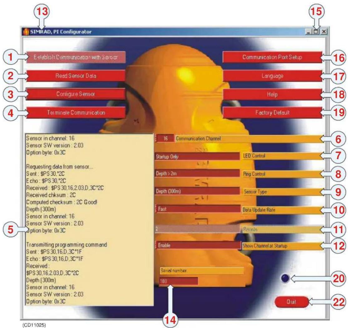
| IDButton/FunctionUse | ||
| 1Establishcommunicationwith sensor | OncethesensorisconnectedtothePC,clicktoinitiate sensorinterface. | |
| 2 | Read sensor data | Click to download current parameter settings from the sensor.Theinformationisshowninthemessagefield (5). |
| 3ConfiguresensorClicktouploadthenew | configurationparameterstothesensor. | |
| IDUse | Button/Function | |
| 4 | TerminatecommunicationClicktodisconnectthesensorfromthePC. | |
| 5 | MessagefieldDisplaysprogramandsensordata. | |
| 6 | Communication channel | Select channel number to be uploaded to the sensor. If aTwinSpreadsensorisconnected,two communicationchannelsmustbedefined. |
| 7 | LED control | Click and drag the slider bar to control the behaviour of the sensor'sinternalLED. |
| 8 | Pingu controlClickanddragthesliderbartocontrolhowoftenther sensorwilltransmit("ping"). | |
| 9 | SensortypeDisplaysthesensortype. | |
| 10 | Data update rate | Select the time interval between data transmissions fromthesensor. |
| 11 | Remote | Only available for Twin Spread sensors, used to definedthesetof Remotesensorstobeusedinthe TwinSpreadsystem. |
| Number | OnlyavailableforRemotesensors, usedtodefineits identificationnumber(1- 4) | |
| 12 | Show channel at startup | Click to activate or deactivate the sensor's internal LED identificationflash. |
| 13 | PI Configurator title | Displays current software version. |
| 14 | Serial number | Displays the sensor's serial number. This parameter is notavailableforPSsensors. |
| 15 | Dialogue box function buttons | Standard operating system functionality. |
| 16 | Communication port setup | Click to select which COM port you use to communicatewiththesensor. |
| 17 | Language | Clicktochangelanguage. |
| 18 | Help | Click to open on-line help. |
| 19 | Factory default | Click to configure the sensor with the corresponding factorydefaultsettings. |
| 20 | Indicator lamp | Indicates sensor interrogation. |
| 21 | Quit | Close the PI Configurator utility. |
Operational procedures
Observethefollowingprocedures.
→ Howtoperformsoftwareinstallation,page234
→ Howtointerfaceesensor, page235
→ Howtoperformbasicsensorconfiguration,page236
→ HowtosetupaTwinSpreadsystem,page237
→ Howtuploadfactorysettings,page239
Softwareinstallation
ObservethefollowingprocedureinstallthePIConfigurator softwareonastationaryorportablecomputer.Notethatthe computermusthaveeitherMicrosoftWindows©2000or MicrosoftWindows©XPoperatingsystem.Youmustalsohave the Winzip utility installed on your computer. if this is not the case,itcanbedowloadedfromwww.winzip.com_.
Note: Certainantivirus applications may cause the installation process to fail. If you suspect this, closed down the antivirus protection, and reinstall the PIC configurator.
1 Locate the zip file containing the PI Configurator utility. -ThefilecanbefoundonaCD, itcanbedownloaded, ordistributedbye-mail.
2 Copy the zip file to your harddrive, and open it. - The Winziputilityisrequiredtoopenthefile.
3 Unpacktheinstallationfilestoatemporaryfolderonyour harddrive.
4 Locate and run the setup.exe file.
5 Allowtheinstallationwizardtostart.Followtheonline instructionscarefully.
Note: If you have a previous version of the PIC configurator utility, the installation program will remove it. You will then need to restart the setup.exe file to complete the installation of the new version.
TheuserguideisavailableinelectronicformonthePI ConfiguratorCD.ItmaybeviewedbyopeningtheCD's contentsanddouble-clickingthefile.
How to interface the sensor
Beforeyoucanconfigurethesensor,youneedtoconnectitto thecomputer. Observetheprocedurebelow.
1StartthePIC configuratorutility.
2Plugtheprogrammingcableintooneofcomputer'sCOM ports(COM1isrecommended).
3Ensurethatthesensortobeconnecteddisswitchedoff. CheckthattheinternalLEDdoesnotflash,andthatthe seawaterswitchisnotactivatedinanyway.
4 Attachtheprogrammingcable'spositive(red)alligator cliptooneofthesensor'spositivefasteninglugs (designatedwithaplussymbol).
5Attachtheprogrammingcable'snegative(black)alligator cliptooneofthesensor'snegativefasteninglugs (designatedwithaminussymbol).
6InthePIConfiguratorutility, clicktheCommunication Port Setup button to open the Com Port Setup dialogue box.

7SelecttheCOMporttheprogrammingcableisplugged intobyclickingit,thenclickOK.
8ObservethattheEstablishCommunicationwithSensor buttonhasbeenactivated.
9 Click the Establish Communication with Sensor button.
Smalldialogueswilltellyouthatthecomputerfirstopensthe COMport, and then wakes up the sensor. If there is a malfunction, you will be notified accordingly. Once the communication between the PC and interfaced sensors is established, they yellow text field will display the key parameters retrieved from the sensor. Also, the indicator lamp in the lower right-hand corner of the PIC configurator dialogue will turn on and off every two seconds. The indicator lamp inside the sensor will illuminate at the samerate.
How to perform basic configuration
Oncethesensorisconnectedtothecomputer, and you have established communication, you can us the PIC configurator utility to changethe basicsensor parameters.
1ClicktheReadSenorDatabutton.
- Observethatthecurrentsensorconfiguration parametersaredisplayedinthemessagefield. The informationincludessensortype,channelnumber,and thesensor'ssoftwareversion.
2Ifrequired,selectanewcommunicationchannelinthe spinboxnexttotheCommunicationchannellabel.
3Ifrequired,selectadifferentupdaterateinthespinbox nexttotheDataupdateratelabel.
4 Press the Configure sensor button to upload the new parameters.
5 Press Terminate communication, and disconnect the sensor.
HowtoconfigureaTwinSpreadsystem
ThisproceduredescribeshottosetupaTwinSpreadsystem usingoneTwinSpreadsensorandtwoRemotesensors.
Setting up the Twin Spread sensor
1ConnecttheTwinSpreadsensortothePIConfigurator.
2 Press Establish communication with Sensor.
- Observethatthecurrentsensorconfiguration parametersaredisplayedinthemessagefield. The informationincludessensortype,channelnumber,and thesensor'ssoftwareversion.
3Ifrequired,selectnewcommunicationchannelsinthe spinboxesnexttotheCommunicationchannellabels.
-Twocommunicationchannelsarerequiredbecausethe TwinSpreadsystemmeasuretwodifferentdistances. ThechannelsyouselecthereMUSTmatchthe channelsyouselectionthePI44.
4Ifrequired,selectadifferentupdaterateinthespinbox nexttotheDataupdateratelabel.
5 Use the spin box next to the Remote label to choose the setofRemotesensoryouwishtouse.
- You can either use Remote set 1 and 3 or 2 and 4. - TheselectionyoumakehereMUSTmatchthetwo Remotesensorsyouwishtouse.
6 Press the Configure sensor button to upload the new parameters.
7 Press Terminate communication, and disconnect the sensor.
Setting up the first Remote sensor
1ConnectthefirstRemotesensortothePIConfigurator.
2 Press Establish communication with Sensor.
- Observethatthecurrentsensorconfiguration parametersaredisplayedinthemessagefield.
3 Use the spin box next to the Number label to define the sensor'snumberintheTwinSpreadsystem.
-ThenumberyouchooseMUSTmatchoneofthe numberschoseninstep5intheTwinSpreadsensor setup.
4 Press the Configure sensor button to upload the new parameters.
5 Press Terminate communication, and disconnect the sensor.
Setting up the second Remote sensor
1ConnectthesecondRemotesensortothePIConfigurator.
2 Press Establish communication with Sensor.
- Observethatthecurrentsensorconfiguration parametersaredisplayedinthemessagefield.
3 Use the spin box next to the Number label to define the sensor'snumberintheTwinSpreadsystem.
-ThenumberyouchooseMUSTmatchtheother numberchoseninstep5intheTwinSpreadsensor setup.
4 Press the Configure sensor button to upload the new parameters.
5 Press Terminate communication, and disconnect the sensor.
How touploadfactorysettings
Oncethesensorisconnectedtothecomputer, and you have established communication, you can us the PIC configurator utility to upload the applicable sensor's factory settings.
1ClicktheReadSenorDatabutton.
- Observethatthecurrentsensorconfiguration parametersaredisplayedinthemessagefield. The informationincludessensortype,channelnumber,and thesensor'ssoftwareversion.
2 Click the Factory default button to retrieve the default parameters for the current sensor.
3 Press Configure sensor button to upload the parameters tothesensor.
4 Press Terminate communication, and disconnect the sensor.
References
ThefeaturesavailablewhenusingPIConfiguratorsoftware depend which mode it is in (Standard or Professional) and the typeofsensorathatisinterface. All commands are described here, and they are listed in alphabetical order.
→ CommunicationChannel, page241
→ CommunicationPortSetup, page242
→ ConfigureSensor, page243
→ DataUpdateRate, page244
→ EstablishCommunicationwithsensor,page245
→ FactoryDefault, page246
→ Help, page247
→ Language, page248
→ LEDcontrol,page249
→ Messagefield, page250
→ Number,page251
→ Pingcontrol, page252
→ Quit,page253
→ ReadSensorData, page254
→ Remote,page255
→ SensorType,page256
→ Serialnumber,page257
→ Showchannelatstartup, page258
→ TerminateCommunication,page260
CommunicationChannel
Thisparameterallowsyoutoredefinethesensor'stransmission channel(1to30).
Sensorssendinformationusingspecificfrequencies, each designated as an individual channel. PI and PS sensors have 30 channelstochoosefrom,andtheFA701sensorshavefour.The frequencyrangeofthesechannelsareoffrom43.5to49.5kHz for PI and PS systems, and 70 to 80 kHz for FA710 systems.
Note: Thisisakeyparameter.Unlessthecommunicationchannel definedinthesensormatchesthechanneldefinedonthehostPI system,thecommunicationwillnotwork!
Operation
Tooperate, click the upordownarrow on the Communication Channel spinbox until the desired channel is shown in the text box. It is also possible to enter a channel directly by clicking the textbox and inputting the value with the PC's keyboard.
ClicktheConfigureSensorbuttontoprogramtheinterfaced sensorwiththenewchannelnumberparameter.Finally,check thatthemessagefieldisupdatedwiththenewparameter,and thatthemessageSuccess!!isdisplayedatthebottomas confirmationthatthecommandwasexecuted.
Spread sensors
NotethatSpreadsensorscanbeconfiguredtocommunicate withRemotesensorsNo.1or2;butshouldbelabelled accordinglybecausetheymustbeusedinpairsandcannotbe interchanged.Itisimportanttoremembertore-configurethe Spread2communicationchannel.
Note: Spread sensors configured as Sensor Type / Twin Spread have two CommunicationChanneldialogueboxes.
Related topics
→ Remote,page255
CommunicationPortSetup
ThisbuttonopenstheC o m P o r t S e t u p dialogue. The integrated sliderbarisusedtodesignate which COMport(COM1 to COM8) the programming cable is plugged into. COM1 is the factory default setting and recommended parameter.
Operation
Tooperate, click the CommunicationPort Setup button to open the C o m P o r t S e t u p dialoguebox. Click on the desired port, or use the slider bar to select. Click OK to save and exit.
If the chosen COM port is unavailable on the computer, a corresponding message will inform you about this.
ConfigureSensor
Thisbuttonisusedtore-programthecurrentlyinterfacedsensor withthenewparametersselected(thosepresentlydisplayed).
Thisoperationcannotbe“undone”however,thesensor’s previousstatusinformationandparameterconfigurationisstill availableinthemaindialogueboxandmaybere-enteredif necessary.
Operation
To operate, click the Configure Sensor button to program the sensorwiththenewparametersshownonthescreen.Checkthat themessagefieldisupdatedwiththenewparametersandthe messageSuccess!!isdisplayedatthebottomasaconfirmation thatthecommandwasexecuted.
DataUpdateRate
Thisparameterisusedtoselectaninterfacedsensor'sdata updaterate.
Note: Thisisakeyparameter.Unlessthedataupdateratedefinedin thesensormatchestherateddefinedonthehostPIsystem,the communicationwillnotwork!
The data update rate is the time interval between individual transmissions from the sensor containing measurement data. The rates selected must match the corresponding setting in the PI Cabinet's Setup window.
Operation
Tooperate, click the spinbox next to the Data Update Rate label. Select the desired rate. Then, click the Configure Sensor button to program the interfaced sensor with the new data updaterate parameter. Finally, check that the message field is updated with the new parameter, and that the message success!! is displayed at the bottom as confirmation that the command was executed.
Related topics
→ Aboutsensorconfiguration, page229
Establish Communication With Sensor
Thisbuttoninitiatescontactbetweenthecomputerandawell chargedsensorbysendingita"wake-up"command.
Oncetwo-waycommunicationisestablishedthefollowing occurs:
- Theindicatorlamp(inthelowerright-handcornerofthe dialogue)willbeturnedonandoffeverytwoseconds.
- TheLEDinsidetheinterfacedsensorwillilluminateevery twoseconds.
- Thesensorwilldownloaditscurrentconfigurationdatatothe PC.Theinformationisshowninthemessagefield.
Operation
Tooperate:clicktheEstablishCommunicationwithSensor button.Checkthatthemessagefieldshowstheinterfaced sensor'scurrentconfigurationparameters,andthatethemessage Success!!isdisplayedasconfirmationatthebottomofthetext.
Toterminatethecommunicationwiththesensor,clickthe TerminateCommunicationbutton.
FactoryDefault
Thisbuttonisusedtorestoreasensor'sfactorydefaultvalues, accordingtothetypeofsensorcurrentlyinterfaced.
Factorydefaultsettingsinclude:
- SensorCommunicationChannel
- LEDcontrol
- Pingcontrol
- DataUpdaterate
- Remote
• ShowchannelwithLEDflashatstartup
Operation
Tooperate, click the Factory Default button to select the original factory default settings. Then, click the Configure Sensor button to program the interfaced sensor with the original factory default settings. Finally, check that the message field is updated with the factory default settings, and that the message Success!! is displayed at the bottom as confirmation that the command was executed.
Help
Thisbuttonopenstheon-lineHelp.
Theon-linehelpincludegeneralinformationconcerningtheuse ofPIConfiguratorsoftwareandsensorinterface.
Tooperate, click the Help button to open the on-line help.
Toaccesscontextsensitivehelp, clicktherightmousebutton overagivenbuttonorparameter. This will open help window with specific information concerning the parameter or button the cursor is located over.
Language
ThisbuttonopenstheLanguagedialogue.
Thedialogueallowsyoutoselectoperationallanguageby clickingononeoftheflagicons.Clickinganiconwillconvert thePIConfigurator'sbuttons,information,helpfunctionsand interfacedsensordatatotherespectivelanguage.
Operation
Tooperate, click the Language button to open the dialogue. Click on the desiredicontoselect language, or click Cancel to closeted dialogue without replacing the present language in use.
When you have changed the language, click the Configure sensor button to have the information in the message field translated.
LEDControl
ThisparametercanonlybeaccessedintheProfessionalmode.
Thedialogueboxisusedtocontrolthebehaviourofthe interfacedsensor'sinternalLEDduringnormaloperation.LED behaviourinboththechargeandcommunicationmodescannot bealtered.SensorLEDparametersare:
- StartupOnly-TheLEDwillonlyilluminate(flashingits identificationcode)whenitisenergized.Itwillnotbeturned onduringnormaloperation.
- OnlywhenPinging-TheLEDwillonlyilluminatewhenit "pings"(transmitsdata).
- When<2m-TheLEDwillflasheverytimethesensor "pings",butonlywhenitisatadepthoflessthanttwo meters.Thisparameterisonlyavailablefordepthsensors.
- Always - If the sensor is disabled from pinging at depths less than two meters by the Ping Control parameter being set to Depth > 2m, the Always parameter causes the sensor's LED toilluminateatdepthsoflessthantwometersevenwhenthe sensordoesnot"ping".
Operation
Tooperate, usetheLEDControlspinbuttontoselectthe desiredLEDbehaviour. Then, clicktheConfigureSensor buttontoprogramtheinterfacedsensorwiththenewparameter. Finally, check thatthemessagefieldisupdatedwiththenew parameter, and thatthemessageSuccess!! is displayed at the bottomasconfirmationthatthecommandwas executed.
Messagefield
Thismessagefielddisplayspresentandpastconfigurationdata, communicationstatus, errormessagesandotherinformation. Configuredparameterscannotbe"undone"however,the previousparameterconfigurationisstillavailableinthemain dialogueboxandmaybere-enteredifnecessary.
EachtimetheConfigureSensorbuttonisclicked,themessage fieldwillbeautomaticallyupdated. Thelateststatusinformation andparameterswilldisplace(vertically)theoldervaluestuntil theyarenolongerdisplayedinthewindow.

(1)=Previousstatusinformationand parameters
(2)=Newstatusinformationand parameters
Tooperate, click the Configure Sensor buttonoupdatethemessagefield information. Check that the message field was updated and the message Success!! displayed at the bottom as confirmation that the command was executed.
Number
Thisboxallowsyoutodefinetheidentificationnumberforthe currentlyconnectedRemotesensor. Thisisakeyparameter whenyousetupaTwinSpreadsystem.
Related topics
→ HowtosetupaTwinSpreadsystem,page237
Pingcontrol
Thisparameterisonlyavailablefordepthsensors, andcanonly beaccessedintheProfessionalmode.
Thedialogueboxisusedtocontrolwhenasensorwill“ping”(transmitanacousticsignal).Forexample,itispossibleto disablethesensorfrombeinginadvertentlyactivatedwhenlying inawetnetondeck(adepthoflessthantwometers)toprolong itsbatterylife.Theavailableparametersare:
- Always-Thesensorwill "ping" atalldepthsduringnormal operation.
- Depth>2m-Thesensorwill“ping”onlywhenitisata measureddepthofmorethantwometers(deployed).
Operation
Tooperate, clickthePingControldialogueboxanddragthe sliderbartoselectthedesired“ping”behaviour. Then, clicktheConfigureSensorbuttontoprogramtheinterfacedsensorwith thenewPingControlparameter.Finally, checkthatthe messagiefiledisupdatedwiththenewparameter, and thatthe messageSuccess!!isdisplayedatthebottomasconfirmation thatthecommandwasexecuted.
Quit
ClickthisbuttontoclosethePIConfiguratorutility.
ReadSensorData
Thisbuttonrequeststhatconfigurationdatabesentfromthe interfacedsensortothePC.
WhentheReadSensorDatabuttonisclicked,thesensorwill downloadinformationtothePC.Thisdataisthenusedto populatethemessagefieldjustaswhentheEstablish CommunicationwithSensorbuttonisclicked.
Operation
Tooperate, click the Read Sensor Databutton. Check that the message field is populated with the interfaced sensor's data and the message success!! is displayed as confirmation that the command was executed.
Remote
ThisparameterisonlyavailableforSpread,TwinSpreadand Remotesensors. Thedialogueboxallowsselectionofthe channelsusedtocommunicatebetweenSpreadandtheRemote sensors.
Note: ThesearekeyparameterswhenyouworkwithSpreadand
Remotesensors.Makesurethecorrectchannelsareselectedfor allthesensors.Shouldincorrectparametersbechosen,the sensorswillnotbeabletocommunicatewitheachother,andthe PIOperatorUnitwilldisplay“±±±”.
TheSpreadandRemotesensorsmustalwaysbesetupinsetsas follows:
Singletrawl:
- Spread 1 must communicate with Remote 1
- Spread 2 must communicate with Remote 2
Twintrawl:
- Twin Spread 1 must communicate with Remote 1 and 3
- Twin Spread 2 must communicate with Remote 2 and 4
ATwinSpreadsensorusestwochannelstocommunicate withtheRemotesensors;onechannelforeachRemote.
Dualtwintrawl:
- Twin Spread 1 must communicate with Remote 1 and 3
- Twin Spread 2 must communicate with Remote 2 and 4
Tosetupadualtwintrawlconfiguration,thetwosetsof TwinSpreadsensorsmustworkwithdifferent communicationchannels.
Operation
UsetheRemotespinbox, and select the desired channel or channel combination. Click the Configure Sensor button to program the interfaced sensor with thenew channel parameter. Check that the message field is updated with thenew parameter and the message success!! displayed at the bottom as confirmation that the command was executed.
SensorType
Thisparameteristobeconfiguredinaccordancewiththe sensor'slabelandcanonlybeaccessedintheProfessional mode.
Thedialogueboxisusedtoselectwhichofthesensor'sinternal programstorunwhenactivated.WhenusingthePI Configurator in the Standard mode, it will only display the type of sensorinterfaced.
Itisnotpossibletochangeasensor'stype.
Operation
Tooperate, click the SensorTypedialoguebox and drag the sliderbartothetype of sensor written on its label. Then, click the ConfigureSensorbutton to toprogram the interfaced sensor with thenew parameter. Finally, check that the message field is updated with thenew parameter, and that the message Success!! is displayed at the bottom as confirmation that the command was executed.
Serialnumber
Thistextboxdisplaystheinterfacedsensor'sserialnumber.It cannotbere-configured. ThisfeatureisnotavailableforPS sensors.
Show ChannelAtStartup
This dialogue box controls weather or not the interfaced sensor will flash a channel identification code using its internal LED when first energized.
WhenEnabledisselected, the sensor will flash its presently configured communication channel number at startup when in thenormal mode (not in the charge or communication modes).
Thisfeaturemayalsobeactivatedbytouchingasensor'slidand charginglugsimultaneously.
When activated, the sensor will respond by flashing its individual LED identification codes, as follows:
(1)=Onelongflash:Ithasadurationofapproximately1 second.
(2)=Onestartflash:Thissignalsthatthefirstdigitofthe channelnumberisnext.
(3)=None,one,twoorthreeshortflashes:Thenumberofshort flashessignifiesthefirstdigitoftheconfiguredchannelnumber.
(4)=Asecondstartflash:Thissignalsthattheseconddigitof thechannelnumberisnext.
(5)=Nonetonineshortflashes: Thenumberofshortflashes signifiesthesseconddigitoftheconfiguredchannelnumber.
Operation
To operate, use the spin box and choose Enable or Disable. Then.clicktheConfigureSensorbuttontoprogramthe interfacedsensorwiththenewparameter.Finally,checkthatthe messagefielddisupdatedwiththenewparameter,andthatthe messageSuccess!!isdisplayedatthebottomasconfirmation thatthecommandwasexecuted.
Examples
Exampleofchannelnumber16atstartup(below):
(1)=Aonesecond"longflash"
(2)=Astart"flash"
(3)=One“quickflash”(firstdigitof16is1)
(4)=Astart"flash"
(5-10)=Six"quickflashes"(seconddigitof16is6)
Normaloperationstarts

flowchart
graph TD
    A["1"] --> B["Block 1"]
    C["2"] --> D["Block 2"]
    E["3"] --> F["Block 3"]
    G["4"] --> H["Block 4"]
    I["5"] --> J["Block 5"]
    K["6"] --> L["Block 6"]
    M["7"] --> N["Block 7"]
    O["8"] --> P["Block 8"]
    Q["9"] --> R["Block 9"]
    S["10"] --> T["Block 10"]
Exampleofchannel2atstartup(below):
(1)=Aonesecondflash
(2)=A"start-flash"
(3)=Noshortflashes(firstdigitof02is0)
(4)=A "start-flash"
(5-6)=Twoshortflashes(seconddigitof02is2)
Normaloperationstarts
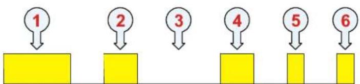
flowchart
graph TD
    A["1"] --> B["Yellow Block"]
    C["2"] --> D["Yellow Block"]
    E["3"] --> F["Yellow Block"]
    G["4"] --> H["Yellow Block"]
    I["5"] --> J["Yellow Block"]
    K["6"] --> L["Yellow Block"]
(CD11012C)
Terminate Communication
Pressthisbuttontoterminatetheserialdataflowbetween the sensorandthecomputer.
Operation
Pressthebuttontoterminatethecommunication,then disconnectthecable.
If you disconnect the cable before you terminate the data flow, the PIC configurator will issue an error message.
Maintenance
Thischaptercontainsinformationrelatedtomaintenance,setup andtroubleshooting.
Topics
→ Programmingmodes,page262
→ Makingaprogrammingcable, page263
→ Troubleshooting, page264
Programmingmodes
Available modes
ThePIConfiguratorutilityhastwoprogrammingmodes:
• Standard-defaultmode,describedinthismanual.
• Professional-forusebySimradpersonnelonly.
Caution: TheuseofPI ConfiguratorsoftwareintheProfessional modeisforqualified Simradpersonnelonly.Improper useofPI ConfiguratorsoftwareintheProfessional modecancausepermanent,irreparabledamageto sensors.Itmustthereforeneverbeactivatedby unqualifiedpersonnel.
To change mode
To activate PI Configurator software in the Professional mode:
1ClosethePICoufiguratorutility.
2 Open the folder C:\Program Files\PI Configurator.
3 Find the file named ps30_cfg.ini and open it with a text editor.
4Locatethelineofcodethatcontainstheword STANDARD and overwrite it to PROFESSIONAL. Makesurethathavea
5Savetheps30_cfg.inifile.
6RestartthePIConfiguratorsoftware.
If you install anewsoftware version, you must repeat this procedure.
After changing modes
AfteractivatingPIConfiguratorsoftwareintheProfessional mode, thestartupscreenwilldisplay:
UKB(unchanged)
COM1(unchanged)
PROFESSIONAL(previouslySTANDARD)
Makingaprogrammingcable
ShouldaSimradprogrammingcablenotbeavailable,itis possibletomakeanadequatesubstitutionasdescribedbelow.
Itisonlypossibletomakeprogrammingcablesforstationary computers. If you wishtouse a portable computer the cable must be ordered from Simrad. Somenewstationary computers have been found to provide the same output specifications as portable computers using lowervoltage on the serial line. On these computers, a “portable” cable is also required.
Youwillneedthefollowingparts:
• A9-pin, Sub-Dfemaleconnector
• Approximatelyonetotwometersof2-wirecable
- A3kohmresistor
- Twoalligatorclamps
Thecableassemblyprocedureisasfollows:
1Connectpinnumbertwoofthe9-pin, Sub-Dfemale connectortooneendofthepositive(+)leadofthe2-wire cable. Attheotherendofthepositive(+)lead, connect thepositive(red)alligatorclamp.
2Connectpinnumberfiveofthe9-pin,Sub-Dfemale connectortooneendofthenegative(-)leadofthe2-wire cable.Attheotherendofthenegative(-),connectthe negative(black)alligatorclamp.
3Connectthe3kohmresistorbetweenpinsnumbertwoand threeofthe9-pin,Sub-Dfemaleconnector.
4Checkbothalligatorclampsandrespectivepinsfor continuity.
Troubleshooting
Mostproblemsareeasilysolved. Troubleshootinterface, configurationorothercomplicationsbycheckingthefollowing:
• Theinterfacedsensorissufficientlycharged.
- ThecorrectPIsensorprogrammingcableisusedandingood condition
- ThePIsensorprogrammingcableisconnectedtothePC's COMportcorrectly.
- ThePIsensorprogrammingcableisconnectedtothesensor correctly.
- ThePIsensorprogrammingcableisconnectedtotheCOM portselectedintheComPortSetupdialoguebox.
- ThemodeofoperationforthePICfiguratorsoftwarehas beencorrectlyselected.
- Thetypeofsensorinterfacedhasthefeatures/parameters attemptingtobeaccessed.
- ThelatestversionofPIConfiguratorsoftwarehasbeen correctlyinstalled.
SENSOR TEST PROCEDURES
Overview
Using the PIC configurator application, you can test the operational status of each sensor. In the following, you will find the test procedures. Not that PI and PS sensors are tested using the same procedures.
Topics
→ BottomContactsensor,testprocedure,page266
→ Catch&Ripsensors,testprocedure,page273
→ Depthsensor,testprocedure,page276
→ Heightsensor,testprocedure,page282
→ Spread&Remotesensors,testprocedure,page269
→ TemperatureSensor,testprocedure,page279
Seawaterswitchdesignchange
TheseawaterswitchdesignonallthePIsensorswaschanged in2005.Onsensorsproducedafterthedesignchange,thesea waterswitchiscomprisedofasacrificialbrassbolt.Thisbolt mustbereplacedwhenandifitisworn.Adedicatedprocedure isprovidedinthePISystemoperatormanual.
Bottom Contact test procedure
Tools and equipment required
- Multimeter
- Asmallpieceofwire
• PIServiceHydrophone(Orderno.314-204480) - PISystem
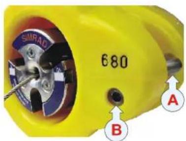
Initial check and setup identification
Keeptheareabetweenthenegativecharginglug(A)andthe waterdetector(B)cleantoreducetheriskofactivating the sensor. If necessary, applysilicongreasetodisruptconductive paths.
1Usingamultimeter,checkthevoltagebetweenthe negativecharginglug(A)andthewaterdetector(B). Makesurethesensorischarged:
-Fullydischarged: Voltagelessthan11.5Vdc
-Fullycharged: Voltagegreaterthan13.5Vdc
-Approximately50%capacityleft:12.8Vdc
2Withasmallpieceofwire,completethecircuitbetween thesensor'sseawaterdetector(B)andnegativecharging lug(A).
- ThesensorwillrespondbyflashingitsindividualLED identificationcodes.

flowchart
graph LR
    A["1"] --> B["2"]
    B --> C["3"]
    C --> D["4"]
    D --> E["5"]
(1)=Onelongflash:Ithasadurationof approximately1second.
(2)=Onestartflash: This signal that the first digit of the channel number is next.
(3)=None,one,twoorthreeshortflashes:The numberofshortflashessignifiesthefirstdigitofthe configuredchannelnumber.
(4)=Asecondstartflash:Thissignalsthatthesecond digitofthechannelnumberisnext.
(5)=Nonetonineshortflashes:Thenumberofshort flashessignifiestheseconddigitoftheconfigured channelnumber.
3Usingamultimeter,checktheDCcurrentbetweenthe negativecharginglug(A)andthewaterdetector(B).
-Withtheinitialseawaterswitchandaafullycharged battery, thecurrentshouldnotexceed150μA.
-Witharedesignedseawaterswitch(sacrificialbolt) andaafullychargedbattery, thecurrentshouldnot exceed67μA.
-Ifyoumeasure0μA, checkthefuseonyour multimeter.
Testing on land
1ConnectthePIServiceHydrophonetothePIOperator Unit.
2Placethesensoronalevelsurfacewithits“domedtop” pointingtowardsthetesthydrophoneapproximatelyfive metersaway.
3 Use the Status display on the PI to monitor the sensor's signalstrength.
-If the interference filter is on, the spectrum displayed should be relatively flat (approximately 25 dB, interference filters at level 9) with a peak detected in the configured channel.
4CheckthatthebottomcontactsymbolonthePIis "touchingthebottom"whenthedetectorwireisnotpulled out.
5Pulloutthedetectorwire, and check that the sensor presentation changes.
Testing in water
1 Disconnect the PIServicehydrophone, and reconnect the vessel's normal hull mounted hydrophone.
2Switchoffthevessel'sechosounders,sonarsandother hydroacousticalequipmenttoavoidinterference.
3Lowerthesensoroverthesideofthevessel.
-Notethattheweightofthesensorinwater (approximately 1.4kg) may not provide sufficient resistancetotriggerthesensor's bottom contact function whenthedetectorwire is pulled. Apply extra weight if required.
4SwitchoffthePIsystem'sinterferencefilter,andobserve thenumericdisplay. -Iftheinterferencesymbolisnotdisplayed,leavethe interferencefilterswitchedofftoincreasethesystem's rangeandperformance.
Note: Shouldanyproblemsariseduringthisprocedure,checkthatthe communicationchannelandupdateratehasbeenconfigured correctly.
5Checkthattheinformationfromthesensorisdisplayedon thePI.
6Engagethesensor, and check that this is registered by the PI.
7 Check the PI Status Display, and record the signal strength.
8Switchonthevessel'sechosoundersandother hydroacousticalequipmentusedduringnormalfishing operations.
9SwitchthePI44interferencefilteronandoff, and observe thenumericdisplay. If the interferences symbol is not shown when the filter is off, leavethe interference filter switched off to increase the system's range and performance.
10Useawater-proofpen, writethesensor's number, configured channel number and any other pertinent information on its label.
-Adedicatedformhasalsobeenprovidedinthefrontof thePIOperatorManualtorecordthisinformation.
Note: Donotwriteonthesensor!Suchinformationmaybe misunderstoodwhenfutureserviceorreplacementisperformed.
Spread & Remote sensors test procedure
Tools and equipment required
- Multimeter
- Asmallpieceofwire
• PIServiceHydrophone(Orderno.314-204480) - PISystem

Initial check and setup identification
Onbothsensortypes, keep the are abetween thenegative charginglug(A) and the water detector(B) cleantoreducethe risk of activating the sensor. If necessary, apply silicongreaseto disrupt conductive paths.
1Onbothsensors, use amultimetertocheck the voltage between the negative charging lug(A) and the water detector(B). Makes sure the sensor is charged:
-Fullydischarged:Voltagelessthan11.5Vdc
-Fullycharged: Voltagegreaterthan13.5Vdc
-Approximately50%capacityleft:12.8Vdc
2Withasmallpieceofwire,completethecircuitbetween thesensor'sseawaterdetector(B)andnegativecharging lug(A).
-ThesensorwillrespondbyflashingitsindividualLED identificationcodes.

flowchart
graph LR
    A["1"] --> B["2"]
    B --> C["3"]
    C --> D["4"]
    D --> E["5"]
(1)=Onelongflash:Ithasadurationof approximately1second.
(2)=Onestartflash: This signal that the first digit of the channel number is next.
(3)=None,one,twoorthreeshortflashes:The numberofshortflashessignifiesthefirstdigitofthe configuredchannelnumber.
(4)=Asecondstartflash:Thissignalsthatthesecond digitofthechannelnumberisnext.
(5)=Nonetonineshortflashes:Thenumberofshort flashessignifiestheseconddigitoftheconfigured channelnumber.
3Usingamultimeter,checktheDCcurrentbetweenthe negativecharginglug(A)andthewaterdetector(B).
-Withtheinitialseawaterswitchandaafullycharged battery, thecurrentshouldnotexceed150μA.
-Witharedesignedseawaterswitch(sacrificialbolt) andaafullychargedbattery, thecurrentshouldnot exceed67μA.
-If you measure 0 A , check the fuse on your multimeter.
Testing on land
1ConnectthePIServiceHydrophonetothePIOperator Unit.
2PlacetheSpreadandRemotesensorsonalevelsurface with their "transversaleyes" pointingtowardseachother atameasureddistance(onetothreemeters). Record this distance.
3Placethetesthydrophoneapproximatelyfivemetersaway fromboththeSpreadandRemotesensors.
4TurnonthePI, and recordthedistanceshownonits display.
5Multiplytherecordedphysicaldistancebyafactorof4.5 andcompareittothedistancedisplayedbythePI.
-Thephysicaldistancebetweenthetwosensors multiplied by 4.5 and the displayed distances shown on the PI should be almost identical.
Testing in water
1DisconnectthePIServicehydrophone, andreconnectthe vessel'snormalhullmountedhydrophone.
2Switchoffthevessel'sechosounders,sonarsandother hydroacousticalequipmenttoavoidinterference.
3LowertheSpreadsensor(A)overthesideofthevessel withitshead(C)pointingtowardsthehydrophone.Lower ittominimumthreemeters.
4SwitchoffthePIsystem'sinterferencefilter,andobserve thenumericdisplay.
-If the interferences symbol is not ____ displayed, leavethe interference filters switched off to increase the system's range and performance.
Lowerthetwo sensorsasshown, andmakesurethat theSpreadsensor's headpointstowards thevessel's hydrophone(C). Also,makesurethat thereisafreelineof sightforthe transverse communication(D).

5OnthePInumericdisplay, verify that thereading is +++.
- This signifest that there is no communication between the Spread and Remotesensors.
6LowertheRemotesensor(B)overtheoppositesideofthe vesselwithitsheadpointinginthesamedirectionasthe Spreadsensor.LowerittothesamedepthastheSpread sensor,andensurethatthereisafreelineofsightforthe transversecommunication(D).
-If both sensors are suspended under the vessel at its widest point, the physical distance between the Spread and Remotesensors is equivalent to the vessel's maximum beam.
7 Observ the P Inumeric display. Thereadings should be the same asthe physical distance (without any compensation) between the two sensors.
Note: Shouldanyproblemsariseduringthisprocedure,checkthatthe type(1or2),communicationchannelandupdateratehavebeen configuredforbothsensors.
8Switchonthevessel'sechosoundersandother hydroacousticalequipmentusedduringnormalfishing operations.
9SwitchthePI44interferencefilteronandoff, and observe thenumericdisplay. If the interferences symbol is not shown when the filter is off, leavethe interference filter switched off to increase the system's range and performance.
10Useawater-proofpen, writethesensor's number, configured channel number and any other pertinent information on its label.
-Adedicatedformhasalsobeenprovidedinthefrontof thePIOperatorManualtorecordthisinformation.
Note: Donotwriteonthesensor!Suchinformationmaybe misunderstoodwhenfutureserviceorreplacementisperformed.
Catch sensor, test procedure
Tools and equipment required
- Multimeter
- Asmallpieceofwire
• PIServiceHydrophone(Orderno.314-204480) - PISystem
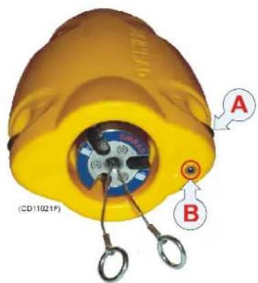
Initial check and setup identification
Keeptheareabteweenthenegativecharginglug(A)andthe waterdetector(B)cleantoreducetheriskofactivating the sensor.Ifnecessary,applysilicongreasetodisruptconductive paths.
1 Using amultimeter, check the voltage between the negative charging lug(A) and the water detector(B). Makes sure the sensor is charged:
-Fullydischarged:Voltagelessthan11.5Vdc
-Fullycharged:Voltagegreaterthan13.5Vdc
-Approximately50%capacityleft:12.8Vdc
2Withasmallpieceofwire,completethecircuitbetween thesensor'sseawaterdetector(B)andnegativecharging lug(A).
- ThesensorwillrespondbyflashingitsindividualLED identificationcodes.
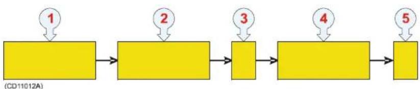
flowchart
graph LR
    A["1"] --> B["2"]
    B --> C["3"]
    C --> D["4"]
    D --> E["5"]
(1)=Onelongflash:Ithasadurationof approximately1second.
(2)=Onestartflash:Thissignalsthatthefirstdigitof thechannelnumberisnext.
(3)=None,one,twoorthreeshortflashes:The numberofshortflashessignifiesthefirstdigitofthe configuredchannelnumber.
(4)=Asecondstartflash: This signal that these second digit of the channel number is next.
(5)=Nonetonineshortflashes:Thenumberofshort flashessignifiestheseconddigitoftheconfigured channelnumber.
3Usingamultimeter,checktheDCcurrentbetweenthe negativecharginglug(A)andthewaterdetector(B).
-Withtheinitialseawaterswitchandaafullycharged battery, thecurrentshouldnotexceed150μA.
-Witharedesignedseawaterswitch(sacrificialbolt) andaafullychargedbattery, thecurrentshouldnot exceed67μA.
-Ifyoumeasure0μA, checkthefuseonyour multimeter.
Testing on land
1ConnectthePIServiceHydrophonetothePIOperator Unit.
2Placethesensoronalevelsurfacewithits“domedtop” pointingtowardsthetesthydrophoneapproximatelyfive metersaway.
3 Use the Status display on the PI to monitor the sensor's signalstrength.
-If the interference filter is on, the spectrum displayed should be relatively flat (approximately 25dB, interference filters at level 9) with a peak detected in the configured channel.
4CheckthattheCatchsymbolonthePIisactivated(red symbolandaudiblealarm)whenoneofthedetectorwire ispulledout.
5Releasethedetectorwire,andcheckthatthesensor presentationchangestoyellow.
Testing in water
1 Disconnect the PIService hydrophone, and reconnect the vessel's normal hull mounted hydrophone.
2Switchoffthevessel'sechosounders,sonarsandother hydroacousticalequipmenttoavoidinterference.
3Lowerthesensoroverthesideofthevessel.
-Notethattheweightofthesensorinwater (approximately 1.4kg) may not provide sufficient resistancetotriggerthesensorfunction when the detectorwirerarepulled. Applyextraweightif required.
4TurnoffthePIsystem'sinterferencefilter,andobserve thenumericdisplay.
-If the interferences symbol is not displayed, leave the interference filters switched off to increase the system's range and performance.
Note: Shouldanyproblemsariseduringthisprocedure,checkthatthe communicationchannelandupdateratehasbeenconfigured correctly.
5Checkthattheinformationfromthesensorisdisplayedon thePI.
6Engagethesensor, and check that this is registered by the PI.
7 Check the PI Status Display, and record the signal strength.
8Switchonthevessel'sechosoundersandother hydroacousticalequipmentusedduringnormalfishing operations.
9SwitchthePI44interferencefilteronandoff, and observe thenumericdisplay. If the interferences symbol is not ____ when the filterisoff, leavethe interference filters switched off to increase the system's range and performance.
10Useawater-proofpen, writethesensor's number, configured channel number and any other pertinent information on its label.
-Adedicatedformhasalsobeenprovidedinthefrontof thePIOperatorManualtorecordthisinformation.
Note: Donotwriteonthesensor!Suchinformationmaybe misunderstoodwhenfutureserviceorreplacementisperformed.
Depth sensor, test procedure
Tools and equipment required
- Multimeter
- Asmallpieceofwire
- PISystem

natural_image
Close-up of a yellow mechanical component with labeled points A and B, no readable text or symbols beyond labelsInitial check and setup identification
Keeptheareabetweenthenegativecharginglug(A)andthe waterdetector(B)cleantoreducetheriskofactivating the sensor.Ifnecessary,applysilicongreasetodisruptconductive paths.
1Usingamultimeter, checkthevoltagebetween the negativecharginglug(A)andthewaterdetector(B). Makesurethesensorischarged:
-Fullydischarged:Voltagelessthan11.5Vdc
-Fullycharged:Voltagegreaterthan13.5Vdc
-Approximately50%capacityleft:12.8Vdc
2Withasmallpieceofwire,completethecircuitbetween thesensor'sseawaterdetector(B)andnegativecharging lug(A).
- ThesensorwillrespondbyflashingitsindividualLED identificationcodes.

flowchart
graph LR
    A["1"] --> B["2"]
    B --> C["3"]
    C --> D["4"]
    D --> E["5"]
(1)=Onelongflash:Ithasadurationof approximately1second.
(2)=Onestartflash:Thissignalsthatthefirstdigitof thechannelnumberisnext.
(3)=None,one,twoorthreeshortflashes:The numberofshortflashessignifiesthefirstdigitofthe configuredchannelnumber.
(4)=Asecondstartflash:Thissignalsthatthesecond digitofthechannelnumberisnext.
(5)=Nonetonineshortflashes:Thenumberofshort flashessignifiestheseconddigitoftheconfigured channelnumber.
3Usingamultimeter,checktheDCcurrentbetweenthe negativecharginglug(A)andthewaterdetector(B).
-Withtheinitialseawaterswitchandaafullycharged battery, thecurrentshouldnotexceed150μA.
-Witharedesignedseawaterswitch(sacrificialbolt) andaafullychargedbattery, thecurrentshouldnot exceed67μA.
-If you measure 0 A , check the fuse on your multimeter.
Testing on land
Thesensorcanonlybetestedinwater.
Testing in water
1LowertheDepthsensoroverthesideofthevesseltoa measureddepthgreaterthantwometers.
2Switchoffthevessel'sechosounders,sonarsandother hydroacousticalequipmenttoavoidinterference.
3SwitchoffthePI44'sinterferencefilter,andobservethe numericdisplay.
-If the interferences symbol is not displayed, leavethe interference filters switched off to increase the system's range and performance.
4 Use the PI44 Status display to monitor the sensor's signal strength.
-If the interference filter is activated, the spectrum displayed should be relatively flat (approximately 25 dB with interference filters at level 9) with a peak detected in the configured channel.
5Checkthatthedepthread-outonthePI44correspondsto theactualmeasureddepthatwhichthesensoris suspended.
-If these values vary, calibratethe PI44 depth offset. The procedure is described below.
6Hoistandlowerthesensorinthewater, and observethat the depthreadout changes accordingly.
7Turnonthevessel'sechosoundersaswellasother hydroacousticalequipmentusedduringnormalfishing operations.
8SwitchthePI44interferencefilteronandoff, and observe thenumericdisplay. If the interferences symbol is not shown when the filter is off, leavethe interference filter switched off to increase the system's range and performance.
9Useawater-proofpen, writethesensor's number, configured channel number and any other pertinent information on its label.
-Adedicatedformhasalsobeenprovidedinthefrontof thePIOperatorManualtorecordthisinformation.
Note: Donotwriteonthesensor!Suchinformationmaybe misunderstoodwhenfutureserviceorreplacementisperformed.
PI32 Calibration procedure
Observethisproceduretocalibratethedepthsensorusingthe functionalityonthePIsystem.
1 Press the Menu button, and select Setup.
2 On the Setup menu, select Sensor alarm/calibration.
3 Press the Enter button to allow the parameters to be changed.
4MovethecursordowntheDepth/Spreadsensor calibration, and switch Depth sensor calibration to ON.
-If these values vary, calibrate by adjusting the PI44 depth offset function until theme measured depth under the vessel correspond to the PI44's displayed depth.
-Another method of calibration is to spend the sensor to measure depth of three meters under the vessel, and then using the PI44's depth sensor calibration functionality. When this calibration procedure is performed, the offset value will be reduced by two meters.
PI44 Calibration procedure
Observethisproceduretocalibratethedepthsensorusingthe functionalityonthePIsystem.
Temperature sensor, test procedure
Tools and equipment required
- Multimeter
- Asmallpieceofwire
• PIServiceHydrophone(Orderno.314-204480)
• Waterproofthermometer - PISystem

natural_image
Close-up of a yellow mechanical component with labeled points A and B, no readable text or symbols beyond labelsInitial check and setup identification
Keeptheareabetweenthenegativecharginglug(A)andthe waterdetector(B)cleantoreducetheriskofactivating the sensor.Ifnecessary,applysilicongreasetodisruptconductive paths.
1 Using amultimeter, check the voltage between the negative charging lug(A) and the water detector(B). Makes sure the sensor is charged:
-Fullydischarged: Voltagelessthan11.5Vdc
-Fullycharged: Voltagegreaterthan13.5Vdc
-Approximately 50% capacityleft:12.8Vdc
2Withasmallpieceofwire,completethecircuitbetween thesensor'sseawaterdetector(B)andnegativecharging lug(A).
-ThesensorwillrespondbyflashingitsindividualLED identificationcodes.
flowchart
graph LR
    A["1"] --> B["2"]
    B --> C["3"]
    C --> D["4"]
    D --> E["5"]
(1)=Onelongflash:1thasadurationof approximately1second.
(2)=Onestartflash:Thissignalsthatthefirstdigitof thechannelnumberisnext.
(3)=None,one,twoorthreeshortflashes:The numberofshortflashessignifiesthefirstdigitofthe configuredchannelnumber.
(4)=Asecondstartflash:Thissignalsthatthesecond digitofthechannelnumberisnext.
(5)=Nonetonineshortflashes: Thenumberofshort flashessignifiestheseconddigitoftheconfigured channelnumber.
3Usingamultimeter,checktheDCcurrentbetweenthe negativecharginglug(A)andthewaterdetector(B).
-Withtheinitialseawaterswitchandaafullycharged battery, thecurrentshouldnotexceed150μA.
-Witharedesignedseawaterswitch(sacrificialbolt) andaafullychargedbattery, thecurrentshouldnot exceed67μA.
-Ifyoumeasure0μA, checkthefuseonyour multimeter.
Testing on land
1ConnectthePIServiceHydrophonetothePIOperator Unit.
2Placethesensoronalevelsurfacewithits“domedtop” pointingtowardsthetesthydrophoneapproximatelyfive metersaway.
3 Use the Status display on the PI to monitor the sensor's signalstrength.
-If the interference filter is on, the spectrum displayed should be relatively flat (approximately 25dB, interference filters at level 9) with a peak detected in the configured channel.
4CheckthatthePI'sdisplayedtemperaturecorresponds withtheactualambienttemperature.
Testing in water
1DisconnectthePIServicehydrophone, and reconnectthe vessel'snormalhullmountedhydrophone.
2Switchoffthevessel'sechosounders,sonarsandother hydroacousticalequipmenttoavoidinterference.
3Lowerthesensoroverthesideofthevessel.
4Lowerthewaterproofthermometeroverthesideofthe vessel, and keepitasclosetothesensoraspossible.
5SwitchoffthePIsystem'sinterferencefilter,andobserve thenumericdisplay.
-If the interferences symbol is not ____ displayed, leavethe interference filters switched off to increase the system's range and performance.
Note: Shouldanyproblemsariseduringthisprocedure, check that the communicationchannelandupdateratehasbeenconfigured correctly.
6CheckthatthePIsystem'sdisplayedtemperature correspondswiththevaluefromthereference thermometer.
7Switchonthevessel'sechosoundersandother hydroacousticalequipmentusedduringnormalfishing operations.
8SwitchthePI44interferencefilteronandoff, and observe thenumericdisplay. If theinterferencesymbolisnot shown when the filterisoff, leavethe interferencefilter switched off to increase the system's range and performance.
9Useawater-proofpen, writethesensor's number, configured channel number and any other pertinent information on its label. -Adedicated form has also been provided in the front of the PIOperator Manual to record this information.
Note: Donotwriteonthesensor!Suchinformationmaybe misunderstoodwhenfutureserviceorreplacementisperformed.
Height sensor, test procedure
Tools and equipment required
- Multimeter
- Asmallpieceofwire
• A referenceechosounder - PISystem

natural_image
Close-up of a yellow mechanical component with labeled parts A and B, no readable text or symbols beyond labelsInitial check and setup identification
Keeptheareabetweenthenegativecharginglug(A)andthe waterdetector(B)cleantoreducetheriskofactivating the sensor.Ifnecessary,applysilicongreasetodisruptconductive paths.
1Usingamultimeter,checkthevoltagebetween the negativecharginglug(A)andthewaterdetector(B). Makesurethesensorischarged:
-Fullydischarged: Voltagelessthan10.4Vdc
-Fullycharged: Voltagegreaterthan12.2Vdc
-Approximately50%capacityleft:11,5Vdc
2Withasmallpieceofwire,completethecircuitbetween thesensor'sseawaterdetector(B)andnegativecharging lug(A).
- ThesensorwillrespondbyflashingitsindividualLED identificationcodes.

flowchart
graph LR
    A["1"] --> B["2"]
    B --> C["3"]
    C --> D["4"]
    D --> E["5"]
(1)=Onelongflash:Ithasadurationof approximately1second.
(2)=Onestartflash: This signal that the first digit of the channel number is next.
(3)=None,one,twoorthreeshortflashes:The numberofshortflashessignifiesthefirstdigitofthe configuredchannelnumber.
(4)=Asecondstartflash:Thissignalsthatthesecond digitofthechannelnumberisnext.
(5)=Nonetonineshortflashes:Thenumberofshort flashessignifiestheseconddigitoftheconfigured channelnumber.
3Usingamultimeter,checktheDCcurrentbetweenthe negativecharginglug(A)andthewaterdetector(B).
-With the initial seawaters switch and a fully charged battery, the current should not exceed 150μA.
-Witharedesignedseawaterswitch(sacrificialbolt) andaafullychargedbattery, thecurrentshouldnot exceed67μA.
-If you measure 0μA, check the fuse on your multimeter.
Testing on land
Thesensorcanonlybetestedinwater.
Testing in water
1Usethevessel'smostaccurateechosounderasreference, andmeasurethewaterdepthbelowthekeel.
2LowertheHeightsensoroverthesideofthevessel.Make surethattheechosoundertransducerfacesthebottom.
-Lowerittothesamedepthasofthevessel'secho soundertransducer.
3Switchoffthevessel'sechosounders,sonarsandother hydroacousticalequipmenttoavoidinterference.
4SwitchoffthePI44'sinterferencefilter,andobservethe numericdisplay.
-If the interferences symbol is not ____ displayed, leave the interference filters switched off to increase the system's range and performance.
5 Use the PI44 Status display to monitor the sensor's signal strength.
-If the interference filter is activated, the spectrum displayed should be relatively flat (approximately 25 dB with interference filters at level 9) with a peak detected in the configured channel.
6Checkthatthedepthread-outonthePI44correspondsto theactualdepthmeasuredbythevessel'sechosounder.
7Hoistandlowerthesensorinthewater,andobservethat thedepthreadoutchangesaccordingly.
8Turnonthevessel'sechosoundersaswellasother hydroacousticalequipmentusedduringnormalfishing operations.
9SwitchthePI44interferencefilteronandoff, and observe thenumericdisplay. If the interferences symbol is not shown when the filter is off, leavethe interference filter switched off to increase the system's range and performance.
10Useawater-proofpen, writethesensor's number, configured channel number and any other pertinent information on its label.
-Adedicatedformhasalsobeenprovidedinthefrontof thePIOperatorManualtorecordthisinformation.
Note: Donotwriteonthesensor!Suchinformationmaybe misunderstoodwhenfutureserviceorreplacementisperformed.
TECHNICAL SPECIFICATIONS
Thischapterprovidesthebasictechnicalspecifications.
Topics
→ PISensors,page285
Sensors
Specificationscanbealteredwithoutpriornotification.
PI Bottom Contact
• PISystem:PI32,PI44orPI54
- Updaterates:
-Fast:Every3,2second(approx.)
-Normal:Every5,3second(approx.)
-Slow:Every33second(approx.)
- Defaultupdaterate:Normal
- Lifetimebetweeneachrecharge:
-Fastupdaterate:26hours
-Normalupdaterate:40hours
-Slowupdaterate:175hours
• Communicationfrequencyrange:43,5to49,5kHz
• Defaultcommunicationchannel:6
- Physicalproperties:
-Length:246mm
-Width:171mm
-Thickness:123mm
-Weightinair:4,6kg(withoutchainandgroundweight)
- ChargingtimewithPICharger:
-To70%capacity:1hour
-To100%capacity:4hours
- ChargingtimewithPSCharger: -To100%capacity:16hours
PI Catch & PI Rip
• PISystems:PI32,PI44orPI54
- Updaterates:
-Fast:Every5,3second(approx.)
-Normal:Every33second(approx.)
-Slow:Every125second(approx.)
- Defaultupdaterate:Normal - Lifetimebetweeneachrecharge:-Fastupdaterate:35hours -Normalupdaterate:150hours -Slowupdaterate:300hours
• Communicationfrequencyrange:43,5to49,5kHz
• Defaultcommunicationchannel:4
• Physicalproperties:
-Length:246mm
-Width:171mm
-Thickness:123mm
-Weightinair:4,3kg
• ChargingtimewithPICharger:
-To70%capacity:1hour
-To100%capacity:4hours
• ChargingtimewithPSCharger:
-To100%capacity:16hours
PI Depth
• PISystems:PI32, PI44 or PI54
- Updaterates:
-Fast:Every4,5second(approx.)
-Normal: Every 14 second (approx.)
-Slow:Every34second(approx.)
- Defaultupdaterate:Fast
• Lifetimebetweeneachrecharge:
-Fastupdaterate:24hours
-Normalupdaterate:75hours
-Slowupdaterate:100hours
• Communicationfrequencyrange:43,5to49,5kHz
• Defaultcommunicationchannels:
-100mdepthrange:16
-300mdepthrange:12
-1000mdepthrange:10
• Accuracy: 1% of total range
• Depthranges:100m,300mand1000m
• Physicalproperties:
-Length:246mm
-Width:171mm
-Thickness:123mm
-Weightinair:4,3kg
• ChargingtimewithPICharger:
-To70%capacity:1hour
-To100%capacity:4hours
• ChargingtimewithPSCharger:
-To100%capacity:16hours
PI Height
• PISystem:PI32,PI44orPI54
- Updaterates:
-Fast:Every5,5second(approx.)
-Normal: Every 14 second (approx.)
-Slow:Every34second(approx.)
- Defaultupdaterate:Fast
• Lifetimebetweeneachrecharge:
-Fastupdaterate:35hours
-Normalupdaterate:60hours
-Slowupdaterate:250hours
• Echosounderfrequency:70kHz
• Echosounderrange:0,7to60m
• Communicationfrequencyrange:43,5to49,5kHz
• Defaultcommunicationchannel:14
• Physicalproperties:
-Length:300mm
-Width:205mm
-Thickness:131mm
-Weightinair:6,8kg
• ChargingtimewithPICharger:
-To70%capacity:1hour
-To100%capacity:4hours
PI Spread& Remote
• PISystems:PI32, PI44 or PI54
- Updaterates:
-Fast:Every5,5second(approx.)
-Normal: Every 14 second (approx.)
-Slow:Every34second(approx.)
- Defaultupdaterate:Fast
• Lifetimebetweeneachrecharge:
-Fastupdaterate:45hours
-Normalupdaterate: 100 hours
-Slowupdaterate:150hours
• Communicationfrequencyrang:43,5to49,5kHz
• Defaultcommunicationchannel:2
• Accuracy:0,2%
• Maximumrange:350meters
• Physicalproperties(Spread/Remote):
-Length:298/248mm
-Width:149/121mm
-Thickness:120/98mm
-Weightinair:5,7/2,9kg
• ChargingtimewithPICharger:
-To70%capacity:1hour
-To100%capacity:4hours
• ChargingtimewithPSCharger:
-To100%capacity:16hours
PI Temperature
• PISystems:PI32,PI44orPI54
- Updaterates:
-Fast:Every4,5second(approx.)
-Normal: Every 14 second (approx.)
-Slow:Every34second(approx.)
- Defaultupdaterate:Fast
• Lifetimebetweeneachrecharge:
-Fastupdaterate:24hours
-Normalupdaterate:75hours
-Slowupdaterate:150hours
• Communicationfrequencyrange:43,5to49,5kHz
• Defaultcommunicationchannel:8
• Accuracy:0,2%
• Physicalproperties:
-Length:246mm
-Width:171mm
-Thickness:123mm
-Weightinair:4,3kg
• ChargingtimewithPICharger:
-To70%capacity:1hour
-To100%capacity:4hours
• ChargingtimewithPSCharger:
-To100%capacity:16hours
SOFTWARE UPDATES
Overview
YoucanupdatetheoperationalsoftwareinthePI44Operator Unityourselfbyfollowingtheproceduresprovided.Thereare twodifferentprogramsthatmustbeupdatedindependently:
• DPS(DigitalSignalProcessor)
• MMI(Man-MachineInterface)
ThesoftwarecanbedistributedonCDs, bye-mailorby downloadingthefilesfromSimrad'swebsite.
Inordertoperformthesoftwareupdates,youwillneeda personalcomputerwithaseriallineconnector,andaspecial uploadcable.
Note: Even though the software update procedures are uncomplicated,
Simrad cannot be held responsible for errors or malfunctions that may occur after as software update, if the update has not been performed according to the procedures, or a result of technical problems during the upload process.
Topics
→ DSPSoftwareupdate, page292
→ MMISoftwareupdate,page296
→ ThePIDSPUploadapplication,page299
DSP Software upgrade
Purpose
TheDSPsoftwareisusedbythedigitalsignalprocessorinside thePI44OperatorUnit.Thisprocessorcontrolsthe interpretationofthecodedsignalsfromthesensors.Changing theDSPsoftwarewillnotchangeanyofthemenusor presentationsonyourPI44.
How to check the current version
Tocheck which DSP software version that is currently installed on your PI44, observ the following procedure.
1 Press the MENU button to open the main menu.
2 Select Fishery on the main menu, and then Status display.
3 In the top right corner of the Status display presentation, justbeneaththenumericpresentation,youwillreadthe followingsentence:DSP=y.zz
-y.zisthecurrentsoftwareversioninuse.
-Whenanewsoftwareversionisreleased, it will always have a higher number.
Prerequisites
InordertoupgradetheDSPsoftware,youwillneedthe followingtoolsandequipment:
- Apersonalcomputer(desktoporlaptop)withoperating systemMicrosoft®Windows2000®orWindowsXP®and witha9-pinseriallineconnector.
• NMEA1PCdatacable(Orderno.298-079852)
• PIDSPUploadprogram(Orderno.880-281039)
• DSPSoftware(Orderno.880-281036)
Notethatoncetheuploadprocesshasstarteditwilltakemore thanonehourtocompleteit!
Theprogramfile
TheDSPsoftwareprogramfileisprovidedonthefollowing format:
281036xxDSPVyzz.hex
- 281036isthelastpartoftheordernumber,andSimrad's internalidentificationnumberforthissoftware.
- xxisaninternalversioncode.
• DSPidentifiesthesoftware. - Vyzidentifiesthesoftwareversion. Youmustreadthe informationasVyzz.
- .hex means that the file is on hexadecimal format.
Procedure
InordertougradetheDSPsoftware, observethefollowing procedure.
1SwitchoffthePI44.
2Powerupyourcomputer.
3ConnecttheNMEA1PCdatacablebetweenthe9-pin seriallinemaleD-connectoronyourcomputerandthe NMEA1socketontherearsideofthePI44OperatorUnit.
4SwitchonthePI44.
5 Open the Status display presentation and leave the PI44 onthatpage.
6 Start the PI DSP Upload program on your computer.
7SelecttheCOMPort(seriallineconnector)youhaveused toconnecttheinterfacecable.
-If you havemorethanoneseriallineconnector and you donot know which is which, just try out the different COM ports until it works. Antimeouterrormessage will inform you if you have chosen the wrong COM port.
8 Click the Select file button to select the DSP software programfile.
-Thesoftwarefileisprovidedon.hexformat. Thefile nameandhowtointerpretithasbeenpreviously explained.
9 If you wish to record the process in a log file, click Want a log file. Then, click the Choose file name button to selectalogfileortocreateanew.
10 Click the Upload file button to start the upload.
11 Observethemessagesprovidedbytheprogram.Theywill keepyouupdatedonthecurrentstatus.
12 Whentheuploadprocesshasbeenstarted, donotswitch offpoweronthePI44orthecomputer, anddonotunplug theinterfacecable.
13 Allow the process to finish. Whenthesoftware has been uploaded, amessagewill inform you.
14SwitchoffthePI44.
15SwitchonthePI44.
16 Verify that thenewsoftware version is shown in the Status display presentation.
Messages
ThePIDSPUploadprogramwillkeepyoupostedonthe processbymeansofmessages.Atypicalsequencefora successfuluploadisprovidedbelowasanexample.
UploadFiletoFlashPROMstarted, Date: 31.05.05 Time: 12:48:48
UploadFileNameis:V001.hex
MESSAGE: THEDSPARENOWINFLASHPROMPROGRAMMING MODE
MESSAGE: FLASHPROMIDENTIFIED
MESSAGE: STARTERASINGSCRATCHPADINFLASHPROM
MESSAGE: STARTPROGRAMMINGSCRATCHPADINFLASH PROM
MESSAGE:PROGRAMMINGSCRATCHPADINFLASHPROM COMPLETED
MESSAGE: STARTERASINGBOOTAREAINFLASHPROM
MESSAGE: STARTMOVINGNEWPROGRAMFROMSCRATCHPAD TOBOOTAREA
MESSAGE: THEDSPHASNOWFINISHEDPROGRAMMINGTHE FLASHPROM
SWITCHPOWEROFFANDONAGAINTOSTARTTHENENEW PROGRAM
UploadFiletoFlashPROMcompletedsuccessfully, Date:31.05.05Time:13:59:17
Safetymeasures
The following safety measures have been implemented to minimize risk of errors during the upload process.
- Whenthesoftwareisuploadedfromthecomputertothe PI44cabinet, thedataarestoredinascratchpad(buffer). ThedataarenottransferredtotheFlashPROM(the microprocessor'sstoragearea)untilallsoftwaredatahave beentransferredcorrectlytothescratchpad.
- If the interface cable is unplugged, or you loose power on the computer and/or the PI44 cabinet during the upload process, you can simply abort the upload and restart it. Error messages will provide guidance.
- WhenthePI44cabinetdetectsthatsoftwareisuploaded, it will automaticallypresentarelevantinformationpage, and thekeypadwillbelocked.Itisnotpossibletoswitchoffthe PI44cabinetduringthesoftwareupload, exceptby disconnectingpower.
Criticalprocess
Onceallthesoftware data have been uploaded correctly to the scratchpad, it will automatically be transferred to the microprocessor (FlashPROM). This is a critical process.
WhenthemessageStarterasingbootareainFlashPROM appearstheinternaltransferprocesshasstarted. Thisprocess willonlylastafewseconds.Theendofthecriticalprocessis identifiedwiththemessageSwitchpoweroffandonagainto startthenewprogram.
If you loose power on the PI44 cabinet during this critical internal transfer process, you cannot restart the upload. You must then contact your Simrad deal to have the PI44 cabinet shipped for reprogramming.
MMI Software upgrade
Purpose
TheMMIsoftwareisusedtocreatethemenusanddisplay presentationsusedinthePI44OperatorUnit,andtoacceptand handletheparametersettings.ChangingtheMMIsoftwaremay changemenus,presentationsandparametersettings,anditmay provideadditionalfeaturesonyourPI44.
How to check the current version
TocheckwhichMMIsoftwareversionthatiscurrentlyinstalled onyourPI44,observethefollowingprocedure.
1 Press the MENU button to open the main menu.
2 Select Fishery on the main menu, and then Status display.
3 In the top right corner of the Status display, just beneath thenumericpresentation,youwillreadthefollowing sentence:Main=y.zz
-y.zzisthecurrentsoftwareversioninuse.
-Whenanewsoftwareversionisreleased, it will always have a higher number.
Prerequisites
InordertougradetheMMIsoftware,youwillneedthe followingtoolsandequipment:
- Apersonalcomputer(desktoporlaptop)withoperating systemMicrosoft®Windows2000®orWindowsXP®and witha9-pinseriallineconnector.
- Uploadcable(Orderno.298-079853)
• MMISoftware(Orderno.880-281037)
NotethattheMMIsoftwareupgradefileincludesanupload programthatwillrunonyourcomputer.
Theprogram file
TheMMIsoftwareupgradefileisprovidedonthefollowing format:
281037xxMMIVyzz.zip
- 281037 is the last part of the order number, and Simrad's internalidentificationnumberforthissoftware.
- xxisaninternalversioncode.
• MMIidentifiesthesoftware. - Vyzz identifies the software version. You must read the informationas Vyzz.
- .zip means that the upgrade file is a “packed” (zipped) file containingnumerousseparatefiles.
Procedure
InordertougradetheMMIsoftware,observethefollowing procedure.
1SwitchoffthePI44.
2Connecttheuploadcablebetweenaseriallineconnector onthecomputerandtheNMEA2connectorontherear sideofthePI44OperatorUnit.
3Onyourcomputer,locatheMMIsoftwareupgradefile (on.zipformat).
4Unpackthefiletoachosendirectoryonyourharddisk.
- Microsoft™ XP™ supports the zip format, and will open the file in an new folder. If your unolder operating systems, you will need the WinZiputility available from www.winzip.com.
5 Allow the installation filestounpack to the chosen directory.
6 Click the Start button at the lower left corner of your computerdisplay, and selectRun.
7Gotothedirectoryyouunpackedtheinstallationfilesto (Step 7), and select upload.exe in the Upload subdirectory.ClickOk.
8SwitchonthePI44.
-Theuploadprogramwillautomaticallydetectwhich seriallineport(COMport)youhaveconnectedthe uploadcableto,andthataPI44cabinetisconnected.
-Theuploadprogramwillfurthercheckyourcurrent softwareversion.IfthecurrentMMIsoftwareonyour PI44OperatorUnitisnewerthantheversionyou attempttoinstall,itwillinformyouofthis.
-Finally, the upload program will start the data transfer.
-Thetransferprogresscanbemonitoredinthemessage field.
9 Allow the transfer process to complete.
10SwitchoffthePI44OperatorUnit.
11Disconnecttheuploadcable.
12SwitchonthePI44OperatorUnit.
13 Verify that the new software version is shown in the Status display.
Messages
TheMMIuploadprogramwillkeepyoupostedontheprocess bymeansofmessages.
Safetymeasures
The following safety measures have been implemented to minimize risk of errors during the upload process.
- Whenthesoftwareisuploadedfromthecomputertothe PI44cabinet, thedataarestoredinascratchpad(buffer). ThedataarenottransferredtotheFlashPROM(the microprocessor'sstoragearea)untilallsoftwaredatahave beentransferredcorrectlytothescratchpad.
- If the upload cable is unplugged, or you loose power on the computer and/or the PI44 cabinet during the upload process, you can simply abort the upload and restart it.
- ItisnotpossibletoswitchoffthePI44cabinetduringthe softwareupload, exceptbydisconnectingpower.
Criticalprocess
Onceallthesoftware data have been uploaded correctly to the scratchpad, it will automatically be transferred to the microprocessor (FlashPROM). This is a critical process.
When the message Blanking Flash appears the internal transfer processhasstarted. Thisprocesswillonlylastafewseconds. Theendofthecriticalprocessisidentifiedwiththemessage
ProgrammingDone.
If you loose power on the PI44 cabinet during this critical internal transfer process, you may not be able to restart the upload. Try onemoretime. If still unsuccessful, contact your Simrad deal alert to have the PI44 cabinet shipped for reprogramming.
PI DSP Upload
Purpose
ThePIDSPUploadapplicationisusedtuploadDSP(Digital SignalProcessor)softwaretothePI44OperatorUnit.The applicationrunsonastandardcomputerwithoperatingsystems Microsoft®Windows2000®orWindowsXP®.
How to install the application
The PI DSP Upload application is provided on an .exe file. To install, observethefollowingprocedure.
1 Locate the *.exe file, and double-click on it to start the execution.
2Selectatemporarydirectorytosavetheinstallationfiles.
3 Press the Start button in the lower left corner of your display, and select Run.
4Selectthedirectoryyouplacedtheinstallationfilesin,and select Setup.exe. Press Ok to start the installation.
5Furtherguidanceisprovidedbytheinstallationprogram.
Howtoruntheapplication
InordertorunthePIDSPUploadprogram,youmustaccessit fromtheStartbuttoninthelowerleftsideofyourscreen. SelectPrograms,andlocatetheapplicationonthemenu.
Howtoremovetheapplication
If you wishtoremovetheapplication from your computer, you must locate the directory where the files are located, and then delete all the files and the directory. The default directory is:
c:\programfiles\PIDSPUload
Thenyoumustmanuallyremovetheprogramshort-cutfromthe Programsmenu.Todothis,findtheshortcutfileanddeleteit. OnaWindowsXPcomputer,youwillfindthisfileatthe followinglocation:
c:\documentsandsettings\
INDEX
Thenextpagesprovideanalphabeticalindextothismanual.
Symbols
\$PSIMP:References189
A
A-Scope, Howto: Operational procedures 95
Additionalinformation,Parameter: References185
ADJ, Buttondescription: Gettingstarted17
AGC, Parameter: References209
Alarm
Clearance:References214
Depth:References181
Fish:References181
Sensors:References212
Setup:References211
Surfacetemperature:References213
Auto, Markerlineparameter: References197
Autopulse/powerrestart, Parameter: References182
Automaticpagerotation, Procedure: Operationalprocedures100
B
B-LCK, Buttondescription: Gettingstarted 18
Backgroundcolour, Howtochangeon echogram: Operationalprocedures90
Backgroundcolour,sensor,Howto: Operationalprocedures56
Batterycharger Description:Systemdescription8 Practicaluse:Batterychargers16
Beamangleoftransducer|,Parameter:References181
Bearingdisplay, Parameter:References201
BottomContactsensor
Numericpresentation:Displaymodes35
Practicaluse(PI):Sensors107
Practicaluse(PS):Sensors111
Specifications: Technical specifications286
Testprocedure: Sensortestprocedures266
Bottomlock, Howto: Operational procedures93
Bottomtrawl, Applicationexample: Applications28
C
C/Bfilter,Parameter:References209
Calculatedmarkerdelay, Trawlcalculator information: References222
Calibration
Depthsensor:References176
Logspeed:References193
Catchsensor
Numericpresentation:Displaymodes36
Practicaluse(PI):Sensors115
Practicaluse(PS):Sensors120
Specifications: Technical specifications286
Testprocedure: Sensortestprocedures273
Catch/BottomSensorFilter, Parameter: References209
Channel
Sensorsetupparameter:References215
Statusdisplayparameter:References218
Charger,Description:Systemdescription8
Clearancealarm, Procedure: Operational procedures97
Clock,internal:References201
CLR, Buttondescription: Gettingstarted19
Clumpsensor, Parameter:References223
Colourscale, Parameter:References185
Colourthreshold
Howtoactivate:Operationalprocedures89
Parameter:References178
CommunicationChannel, Sensorsetup parameter: References215
Communicationrate, Sensorsetupparameter: References215
Configuration,NMEAParameter:References 189
Coursedisplay,Parameter:References201
D
Danishseine, Applicationexample: Applications27
DataoutonNMEA, Parameter:References 181
Dataoutput,NMEAParameter:References 189
Datawindowsensors, Parameter:References 185
Defaultsettings
Parameters:References183
Procedure:Operationalprocedures101
Delay,Markerlineparameter:References198
Demo,Echosounder:References182
Demomode
Parameter:References182
Sensorsetupparameter:References215
Depth
Alarm:References181
Fishalarm:References181
NMEAoutput:References181
Transducer:References181
Depthalarm
Parameter:References181
Procedure:Operationalprocedures96
DepthDSfish,Parameter:References181
Depthgrid
Howtoactivate:Operationalprocedures89
Parameter:References178,185
Depthinput,Parameters:References192
Depthlines:References178,185
Depthofkeel, Parameter:References181
Depthsensor
Howtocalibrate:Operationalprocedures65
Calibration:References176
Howtoadjustoffset:Operationalprocedures 66
Numericpresentation:Displaymodes37
Offset:References203
Practicaluse(PI):Sensors124
Practicaluse(PS):Sensors129
Specifications:Technicalspecifications287
Testprocedure: Sensortestprocedures276
Depthsensorcalibration, Setup:References 176
Det.thresh.,Parameter:References210
DetectionThreshold, Parameter:References 210
Deviceinstance, Parameter:References194
Displaycolours:References205
Displaypresentations,Overview:Display modes32
Displaytextin, Parameter:References204
Doorsensor, Parameter:References223
DT,Parameter:References210
E
Echopresentationsetup:References177
Echoquickmenu: Menusystem172
Echosampling, Parameter:References182
Echosounder, Application example: Applications30
Echosounderdisplay, Description: Display modes50
Echosoundersetup:References180
ENT, Buttondescription: Gettingstarted17
EVENT, Buttondescription: Getting started 17
Expansionwindow, Parameter:References 178,185
F
Factorysettings
Parameters:References183
Procedure:Operationalprocedures101
Fishalarm
Parameter:References181
Procedure:Operationalprocedures96
Footropesensor, Parameter:References223
Frequency, Statusdisplayparameter: References218
Frequencyband, Statusdisplayparameter: References218
Frequencyspectrum:Displaymodes48 NMEAParameter:References189
Freshwaterprofile, Parameter:References 181
G
GAIN, Buttondescription: Getting started 17
Gain, Parameter: References177
Gainindicators:Displaymodes48
Graphicalarm
Howto:Operationalprocedures56
Parameter:References202
Graphicdisplay
Applicationexample:Applications31
Description: Displaymodes41
Graphicsetup:References184
H
Headropesensor, Parameter:References223
Heightmarkerinmainechogram, Parameter: References198
Heightmarker, reference, Parameter: References199
Heightreference,Parameter:References199
Heightsensor
Numericpresentation:Displaymodes38
Practicaluse:Sensors134
Specifications: Technical specifications288
Testprocedure: Sensortestprocedures282
Help, On-line: References207
Highwaydisplay, Description: Display modes53
Howto
A-scope:Operationalprocedures95
Accessechosounderparameters: Operationalprocedures88
Accessgraphicdisplayparameters: Operationalprocedures79
Backgroundcolour,sensor:Operational procedures56
Bottomlock:Operationalprocedures93
Colourthreshold:Operationalprocedures89
Defineinitialpresentationpages:Getting started13
Definewindowinformation:Gettingstarted 12
Depthgrid:Operationalprocedures89
Depthsensorcalibration:Operational procedures65
Depthsensoroffset:Operationalprocedures 66
Echogrambackgroundcolour:Operational procedures90
Graphicalarm:Operationalprocedures56
Markerlines:Operationalprocedures81
Phasedrange:Operationalprocedures91
Pingtopingfilter:Operationalprocedures 89
Range:Operationalprocedures91
Scrollspeed:Operationalprocedures90
Sensorconfiguration:Operational procedures58
Sensormounting:Operationalprocedures61
Sensortimerreset: Operationalprocedures 56
Sensortimers:Operationalprocedures56
Setupapresentationpage:Gettingstarted 11
Signalthreshold:Operationalprocedures89
Spreadsensoroffset:Operationalprocedures 66
Superimposeechodataongraphicdisplay: Operationalprocedures80
Switchpoweronandoff:Gettingstarted10
Trawlinformation:Operationalprocedures 86
Twinspreadsetupfordualtwintrawl: Operationalprocedures72
Twinspreadsetupfortwintrawl: Operationalprocedures67
UpgradeMMIsoftware:Softwareupdates 296
Viewechodataongraphicdisplay: Operationalprocedures80
Waterswitchreplacement:Operational procedures63
Whiteline: Operationalprocedures90
Zoombottomechoes:Operational procedures93
Zoompelagicechoes:Operational procedures94
Hydrophone, Description: Systemdescription 6
|
Input
Navigationparameters:References191
Positionparameters:References190
Waterdepth:References192
Waterparameters:References192
Waterspeed:References193
Watertemperature:References192
Interf.filter,Parameter:References208
Interfacesetup:References187
Interferencefilter, Parameter:References208
Internalclock:References201
K
Keeldepth, Parameter:References181
Keypad, Introduction: Gettingstarted17
L
Language
Parameter:References204
Procedure:Operationalprocedures99
Level,Parameter:References208
Log1, Parameter:References206
Logspeedcalibration, Parameter:References 193,217
M
MainMenu: Menusystem170
Introduction: Gettingstarted16
Manualgain,Parameter:References209
Manualtrawlmarker, Parameter:References 223
Markerlinedelay, Parameter:References198
Markerlineon/off, Parameter:References 198
Markerlinesetup:References197
Markerlinewidth, Parameter:References 198
Markerwhitezone, Parameter:References 198
Marker, height, Parameter: References 198
Marker,sensor,Parameter:References198
Marker, temperature, Parameter:References 198
Masterreset:References183
Maxsh.speed,Parameter:References210
MaxShootingSpeed,Parameter:References 210
Measure, Sensorsetupparameter:References 215
MENU, Buttondescription: Gettingstarted 17
Menulanguage
Parameter:References204
Procedure:Operationalprocedures99
Menusystem: Menusystem 169
MMISoftwareupgrade,Procedure:Software updates296
Mode,Echosounder:References182
MPFilter,Parameter:References209
MPFlevel,Parameter:References209
MultiPathfilter, Parameter:References209
MultiPathFilterLevel, Parameter: References209
N
Navigationparameters, Input:References191
Navigationsetup:References200
NMEAdataout,Parameter:References181
NMEAtelegrams:References195
Numericdisplay,Overview:Displaymodes 33
Numericsetup:References202
O
Offsetadjust, Setup:References203
On-linehelp:References207
Operationalparameters, Output:References 189
OperatorUnit,Description:System description5
Output,Operationalparameters:References 189
P
PAGE, Buttondescription: Gettingstarted19
Pagerotation
Parameter:References204
Procedure:Operationalprocedures100
Pagesetup:References204
Palette, Setup: References205
Pelagictrawl, Applicationexample: Applications29
Personalization, Procedure: Operational procedures 102
Phasedrange, Howto: Operational procedures91
PICharger
Description:Systemdescription8
Practicaluse:Batterychargers165
PIFunction:References189
Pilot/Positionsetup:References200
PingtoPingfilter, Howtoactivate: Operationalprocedures89
Pingtopingfilter,Parameter:References178
Portfortransducer, Parameter:References 181
Positiondisplay
Description:Displaymodes54
Parameter:References200
Positiondisplaysetup:References206
Positionparameters, Input:References190
Power, On/offprocedure: Gettingstarted10
Presentation
Define:Gettingstarted13
Principles:Gettingstarted11
Presentationcolours:References205
Presets,Factory:References183
PSCharger, Description: Systemdescription 8
Purseseine, Application example: Applications26
PWR, Buttondescription: Gettingstarted19
Q
Quickguide:References207
Quickmenu: Menusystem172
R
Range
Howto:Operationalprocedures91
Parameter:References177
Rangestart,Parameter:References177
Receiversetup:References208
Remotesensor
Practicaluse:Sensors143
PracticalusewithTwinSpread:Sensors148
Specifications:Technicalspecifications288
Testprocedure: Sensortestprocedures269
Resetsensortimers, Parameter:References 186,202
RestartofAutopulse/power,Parameter:References182
Ripsensor
Practicaluse:Sensors138
Specifications: Technical specifications 286
S
Saltwaterprofile,Parameter:References181
Scrollspeed
Howtoadjust:Operationalprocedures90
Parameter:References179
Select transducer, Parameter: References 180
Selectorpad, Buttondescription: Getting started17
Sensor,Sensorsetupparameter:References 215
Sensoralarms
Procedure:Operationalprocedures96
Setup:References212
Sensorcharger, Practicaluse: Battery chargers165
Sensorconfiguration, Howto: Operational procedures58
Sensordefinition,NMEAParameter: References189
SensorFilter, Parameter:References209
Sensormarkerinexpansion, Parameter: References198
Sensormounting, Howto: Operational procedures61
Sensorsetup:References215
Sensortimer, Parameter:References186,202
Sensortimerreset, Howto: Operational procedures56
Sensortimers, Howto: Operational procedures56
SensorType, Sensorsetupparameter: References215
Sensors, Introduction: Gettingstarted20
Shearalarm,Parameter:References213
SHIFT, Buttondescription: Gettingstarted 18
Show,Markerlineparameter:References198
Signalthreshold
Howtoactivate:Operationalprocedures89
Parameter:References178
Software,HowtouupgradeMMI:Software updates296
Softwareversion:Displaymodes47
Soundspeed, Parameter:References181
Spectrum,display,Parameter:References218
Speedalarm, Procedure: Operational procedures96
Speeddisplay, Parameter:References200
Speedinput, Parameters:References193
Speedsetup:References217
Spreadsensor
Howtoadjustoffset:Operationalprocedures 66
Numericpresentation:Displaymodes39
Offset:References203
Practicaluse:Sensors143
Specifications:Technicalspecifications288
Testprocedure: Sensortestprocedures269
Statusdisplay, Description: Displaymodes 46
Statussetup:References218
STND, Buttondescription: Gettingstarted 17
Strength, Fishalarm: References181
Superimposeechosounder, Parameter: References184
Surfacetemperature
Description:Displaymodes45
Markerlineparameter:References198
Surfacetemperaturealarm, Procedure: Operationalprocedures97
SWversion:Displaymodes47
System,Description:Systemdescription3
Systemidentification:References194
Systeminstance,Parameter:References194
T
Technicalspecifications:Technical specifications285
Temperaturegrid, Parameter:References219
Temperatureinput, Parameters:References 192
Temperaturemarker, Parameter:References 198
Temperatureoffset, Parameter:References 219
Temperaturescale, Parameter:References 219,220
Temperaturesensor Numericpresentation:Displaymodes40 Practicaluse(PI):Sensors153 Practicaluse(PS):Sensors159 Specifications:Technicalspecifications289 Testprocedure:Sensortestprocedures279
Temperaturesetup:References220
Testprocedures,Sensors:Sensortest procedures265
Timeanddate,Parameter:References201
Timescale, Parameter:References181, 185
Towingspeed, Trawlcalculatorparameter: References221
Transducer,Select:References180
Transducerbeamangle, Parameter: References181
Transducer depth, Parameter: References 181
Transducerport, Parameter:References181
Transducertype, Parameter:References180
Transit,NMEAParameter:References189
Transmitpower, Parameter:References179
Transmitpulselength, Parameter:References 178
Trawlcalculatormode, Parameter: References221
Trawldata, Parameter:References224
Trawldepth, Trawlcalculatorparameter: References222
Trawlinfosetup:References219,223
Trawlmarker, Parameter:References223
Trawlopeningmode, Parameter:References 223
TVG,Parameter:References178
Twinspread
Sensorsetup,dualtwintrawl:Operational procedures72
Setupfortwintrawl:Operationalprocedures 67
TwinSpreadsensor, Practicaluse: Sensors 148
Typeoftransducer,Select:References180
U
Unitdescription,Parameter:References194
Units,Parameter:References225
Unitssetup:References221,225
Update, Sensorsetupparameter: References 215
V
Velocityofsoundinwater, Parameter: References181
Vesselname, Procedure: Operational procedures102
VRM, Buttondescription: Gettingstarted17
W
Waterdepthinput, Parameters:References 192
Waterparameters, Input:References192
Waterprofile, Parameter:References181
Waterspeedinput, Parameters:References 193
Waterswitch, Replacement: Operational procedures63
Watertemperatureinput, Parameters: References192
Watertemperatureoffset,Parameter:References193
Waypointdata, Output: References190
Waypointlocation, Parameter: References 190
Whiteline
Howtoactivate:Operationalprocedures90 Parameter:References177
Whitezone, marker, Parameter: References 198
Width, Markerlineparameter: References 198
WIN, Buttondescription: Getting started 18
Wirelength, Trawlcalculatorparameter: References222
Wirelengthoffset, Trawlcalculator parameter: References222
X
XTEdistance, Parameter:References200
Z
ZOOM, Buttondescription: Gettingstarted 18
Zoom, Howto: Operational procedures 94
©2005SimradAS
ISBN82-8066-046-1
Simrad Horten AS
Strandpromenaden 50
P.O.Box 111
NO-3191 Horten
Norway
Telephone: +47 33 03 40 00
Facsimile: +47 33 04 29 87
www.simrad.com
SIMRAD
A KONGSBERG Company
- Catch monitoring system
- Sim radPI 44
- Catchmonitoringsystem
- Operatormanual
- Important notice
- About this document
- Sections
- l n t r o d u c t i o n
- System description
- Getting started
- Applications
- Display modes
- Operational procedures
- Practical use of the sensors
- Sensor chargers
- M e n u s y s t e m
- References
- PI Configurator
- Sensor test procedures
- Technical specifications
- Software updates
- INTRODUCTION 1....
- SYSTEM DESCRIPTION 3......
- GETTING STARTED 9
- APPLICATION EXAMPLES 25
- DISPLAY PRESENTATIONS 32
- OPERATIONAL PROCEDURES 55
- PRACTICAL USE OF THE SENSORS 103
- SENSOR CHARGERS 164
- MENU SYSTEM 169
- REFERENCES 173....
- PI CONFIGURATOR 226
- SENSOR TEST PROCEDURES 265
- TECHNICAL SPECIFICATIONS 285......
- SOFTWARE UPDATES 291
- INDEX 300
- Sensors
- INTRODUCTION
- Topics
- Changes to this manual
- Rev.A
- Rev.B
- SYSTEM DESCRIPTION
- Operator Unit
- Hull mounted and portable hydrophones
- Sensor overview
- Related topics
- Battery chargers
- PS30 Charger
- PI Charger
- GETTING STARTED
- How to switch power on and off
- Poweron
- Poweroff
- Introducing the presentation principles
- PagesandWindows
- Tosetupapresentationpage
- Todefinewindow information
- Window sizes and information
- Defining initial presentation pages
- Page1:Echosounder
- Page2:Numericdisplay
- Page3:Graphicdisplay
- Page4:Navigationdisplay
- Leafingthroughthepages
- Otherdisplaypresentations
- Introduction to the main menu
- Introduction to the keypad
- Introducing the sensors
- Bottom Contact: Bestatthebottom!
- Catchsensor:Whenisthetrawlfull?
- Depth: How deepcanyougo?
- Heightsensor: Accurated distancetothe bottom!
- Rip:Checkfordamages!
- SpreadandRemote:CheckthetrawIdoors!
- Temperature: Toowarmortoocoldwater?
- APPLICATION EXAMPLES
- Purse seine
- Danish seine
- Bottom trawl
- Pelagic trawl
- Echo sounder
- Graphic display
- DISPLAY PRESENTATIONS
- Numeric display
- Tochangepresentationparameters
- Bottom Contactpresentation
- Catchpresentation
- Depthpresentation
- Heightpresentation
- Spreadpresentation
- Temperaturepresentation
- Numericinformation
- Numericinformation
- Numericinformation
- Numericinformation
- Numericinformation
- Numericinformation
- Additional information
- Timescale
- Depthscale
- A-scopepresentation
- Colourscale
- Bottomecho
- Fishecho
- Information not shown in this example
- Surface temperature
- Status display
- Informationfields
- Upperstatusfield
- Frequency spectrum
- Gainindicators
- Lowerstatusfield
- Echo sounder display
- Bottomexpansion
- A-Scope
- Highway display
- Position display
- Localtimeanddate
- OPERATIONAL PROCEDURES
- Overview
- Sensor procedures
- Graphic display procedures
- Echo sounder procedures
- Common procedures
- How to define sensor presentation
- How to show or hide the graphical alarm
- Howtoshoworhidethesensortimers
- How toresetthesensortimers
- Howtochangethebackgroundcolour
- How to set up the sensors
- Predefinedsettings
- Changingatransmissionchannel
- Changingtheupdaterate
- Howtochangethesensorsetup
- How to mount the sensors on the net
- How to use the sensors
- Applications
- Displaypresentation
- Practicalinformation
- How to replace the sacrificial water switch
- How to test the sensors
- How to calibrate the Depth sensor
- How to define sensor offsets
- How to set up a Twin Spread sensor for twin trawl applications
- Sensorconfiguration
- Communicationchannelsandupdaterate
- Placingthesensorsonthetrawl
- Sensorsetup
- Readoutadjustments
- Readouts
- How to set up two Twin Spread sensors for dual twin trawl application
- How to access graphic display parameters
- Access
- Howtoviewechosounderdata
- How to set up marker lines
- Accesstothemarkerlineparameters
- Trawlcalculator
- DepthandHeightmarkerlines
- Spreadmarkerline
- Surfacetemperaturemarkerline
- Special features for trawl marker lines
- Accesstotheparameters
- Setuptheparameters
- How to access echo sounder parameters
- Echopresentationsetup
- Echosoundersetup
- How to use visual aids and filters
- Pingtopingfilter
- Colourthreshold
- Signalthreshold
- Depthgrid
- Scrollspeed
- Whiteline
- Backgroundcolour
- How to define echo sounder range
- Accesstothedialogue
- Standardmode
- Phasedrangemode
- How to zoom in on bottom echoes
- ActivateBottomLock
- Changetherangeintheexpansionwindow
- De-activateBottomLock
- How to zoom in on pelagic echoes
- ActivateZoom
- Changethereferencedepth
- De-activateZoom
- How to enable A-Scope presentation
- ActivateA-Scope
- De-activateA-Scope
- How to define alarm limits
- Speedalarm
- Fishalarm
- Depthalarm
- Sensoralarms
- Surfacetemperaturealarm
- Clearancealarms
- How to select menu language
- How to control automatic page rotation
- How to restore default settings
- How to personalize your system
- PRACTICAL USE OF THE SENSORS
- Sensor configuration
- Communicationchannelsandupdaterates
- SpecialconfigurationofPI Spread
- Remote2.
- SpecialconfigurationofPI TwinSpread
- PI Bottom Contact sensor
- Purpose
- Mainparts
- Dailyoperation
- System configuration
- Mounting
- Sacrificialwaterswitchsensor
- PS Bottom Contact sensor
- PI Catch sensor
- Presentation
- PS Catch sensor
- PI Depth sensor
- Numericalpresentation
- PS Depth sensor
- PI Height sensor
- PI Rip sensor
- Numericpresentation
- PI Spread and Remote sensors
- Installationprinciple
- Topview:
- Sacrificialwaterswitch sensor
- PI Twin Spread
- PI Temperature sensor
- PS Temperature sensor
- SENSOR CHARGERS
- Indicators
- Automaticconfiguration
- Typicalsensor(PI Depth)
- Generalguidelines
- Batterydepletedfrequently
- MENU SYSTEM
- The main menu
- Fishery
- Echo
- Navigation
- Setup
- Echo quick menu
- Choices
- REFERENCES
- Setup map
- Depth calibration
- Echo presentation setup
- Graphicsetup.
- Echo sounder setup
- Transducerinstallation
- Echosounderparameters
- Factory presets
- Graphic setup
- Interface setup
- Background
- Telegrams
- Configurationwindows
- PI Function
- Position
- Identification
- Applicable telegram formats
- Marker line setup
- Note:
- Navigation setup
- Highwaydisplaypresentationparameters
- Navigation setup:
- Pilot/ Positionsetup
- Numeric setup
- Offset adjust
- Page setup
- Palette setup
- Position display setup
- Pos display setup:
- Quick guide
- Receiver setup
- Sensor alarms
- Surfacetemperaturealarms
- Sensor setup
- Speed setup
- Status setup
- Surface temperature setup
- Temperature setup
- Trawl calculator
- Parameters
- Trawl info setup
- Units setup
- PI CONFIGURATOR
- Procedures
- Reference information
- Maintenance
- Sensor test procedures
- Basic information
- Defaultsensorsettings
- WhocanconfigurePI sensors?
- Programmingmodes
- Necessaryequipment
- Available equipment
- About sensor configuration
- Changing a transmission channel
- Main dialogue description
- Softwareinstallation
- How to interface the sensor
- How to perform basic configuration
- 1ClicktheReadSenorDatabutton.
- HowtoconfigureaTwinSpreadsystem
- Setting up the Twin Spread sensor
- Press Establish communication with Sensor.
- Setting up the first Remote sensor
- Setting up the second Remote sensor
- How touploadfactorysettings
- CommunicationChannel
- Operation
- Spread sensors
- CommunicationPortSetup
- ConfigureSensor
- DataUpdateRate
- Establish Communication With Sensor
- FactoryDefault
- Help
- Language
- LEDControl
- Messagefield
- Number
- Pingcontrol
- Quit
- ReadSensorData
- Remote
- SensorType
- Serialnumber
- Show ChannelAtStartup
- Examples
- Terminate Communication
- Available modes
- To change mode
- Makingaprogrammingcable
- Troubleshooting
- Seawaterswitchdesignchange
- Bottom Contact test procedure
- Tools and equipment required
- Initial check and setup identification
- Testing on land
- Testing in water
- Spread & Remote sensors test procedure
- Catch sensor, test procedure
- Depth sensor, test procedure
- PI32 Calibration procedure
- PI44 Calibration procedure
- Temperature sensor, test procedure
- Height sensor, test procedure
- TECHNICAL SPECIFICATIONS
- PI Bottom Contact
- PI Catch & PI Rip
- PI Depth
- PI Height
- PI Spread& Remote
- PI Temperature
- SOFTWARE UPDATES
- DSP Software upgrade
- How to check the current version
- Prerequisites
- Theprogramfile
- 281036xxDSPVyzz.hex
- Procedure
- Messages
- Safetymeasures
- Criticalprocess
- MMI Software upgrade
- Theprogram file
- 281037xxMMIVyzz.zip
- ProgrammingDone.
- PI DSP Upload
- How to install the application
- Howtoruntheapplication
- Howtoremovetheapplication
- INDEX
- Symbols
- A
- B
- C
- D
- E
- F
- G
- H
- |
- K
- L
- M
- N
- O
- P
- Q
- R
- S
- T
- U
- V
- W
- X
- Z
Brand : SIMRAD
Model : PI44
Category : Browser