CEQ231 - DJ Equipment Citronic - Free user manual and instructions
Find the device manual for free CEQ231 Citronic in PDF.


| Product Type | 31-Band Graphic Equalizer |
| Channels | 2 (Stereo) |
| Frequency Bands | 31 ISO bands per channel |
| Frequency Range | 20 Hz – 20 kHz |
| Input Connectors | 2 x XLR, 2 x 1/4" TRS |
| Output Connectors | 2 x XLR, 2 x 1/4" TRS |
| Input Impedance | 20 kΩ (balanced) |
| Output Impedance | 100 Ω (balanced) |
| Maximum Input Level | +21 dBu |
| Maximum Output Level | +21 dBu |
| Signal-to-Noise Ratio | > 95 dB |
| Total Harmonic Distortion | < 0.005% |
| Frequency Response | 20 Hz – 20 kHz, ±0.5 dB |
| Controls | 31 sliders per channel, bypass switch, level control |
| Indicators | LED level meters, power LED |
| Power Supply | AC 110-240V, 50/60 Hz (internal) |
| Power Consumption | 15 W |
| Dimensions (W x D x H) | 483 x 200 x 88 mm (19" rack, 2U) |
| Weight | 4.2 kg |
| Cooling | Natural convection (no fan) |
| Maintenance | Clean with dry cloth; avoid liquids |
| Safety Compliance | CE, RoHS |
| Spare Parts / Repairability | Contact Citronic support; sliders and connectors replaceable |
Frequently Asked Questions - CEQ231 Citronic
User questions about CEQ231 Citronic
0 question about this device. Answer the ones you know or ask your own.
Ask a new question about this device
Download the instructions for your DJ Equipment in PDF format for free! Find your manual CEQ231 - Citronic and take your electronic device back in hand. On this page are published all the documents necessary for the use of your device. CEQ231 by Citronic.
USER MANUAL CEQ231 Citronic
- Switchable Bypass per channel
- Switchable Low Cut filter per channel
• Independent Gain controls - ±12dB adjustment per band
• Balanced or unbalanced signal path
• LED VU display per channel

Caution: Please read this manual carefully before operating
Damage caused by misuse is not covered by the warranty
Introduction
Thank you for choosing a Citronic equalizer unit. This product has been designed to deliver professional tone-shaping facilities with reliable and accurate function. In order to achieve the best results from this equipment and avoid damage through misuse, please read and follow these instructions and retain for future reference.
Warning
To prevent the risk of fire or electric shock, do not expose any part of the unit to rain or moisture. If liquids are spilled on the surface, stop using immediately, allow unit to dry out and have checked by qualified personnel before further use.
Avoid impact, extreme pressure or heavy vibration to the unit.
There are no user serviceable parts inside the equalizer—refer all servicing to qualified service personnel.
Safety
- Check that the supplied mains lead is in good condition and the supply voltage is correct.
- Ensure signal leads are of good condition and connected to appropriate inputs/outputs
- Do not allow any foreign particles to enter the console through slider or connector apertures
Placement
- Keep out of direct sunlight and away from heat sources.
- Keep away from damp or dusty environments.
- When rack-mounting, avoid placing heavy units above the unit and ensure all connectors are accessible
Cleaning
• Use a soft cloth with a neutral detergent to clean the casing as required
- Use a soft brush to clear debris from the control surface
- Do not use strong solvents for cleaning the unit.
Front Panel
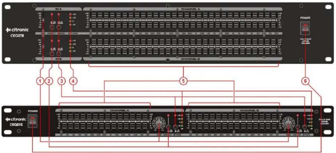
1 Independent GAIN controls
2 LOW CUT filter switches and indicators
3 IN/OUT bypass switches and indicators
4 LED VU indicators
5 Frequency sliders
6 Power button
Rear Panel
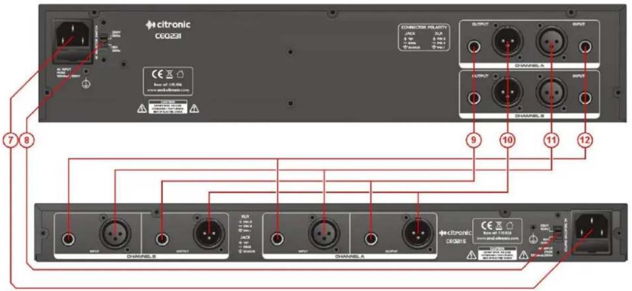
7 Independent GAIN controls
8 LOW CUT filter switches and indicators
9 IN/OUT bypass switches and indicators
10 LED VU indicators
11 Frequency sliders
12 Power button
3 170.923UK, 170.926UK User Manual
What is Equalization?
Equalization (or EQ) is so called because its primary function is to accurately “equalize” or balance the frequency profile of a signal for a given application or environment. This is especially noticeable in large rooms, which can emphasise “boominess” in the low frequencies or rooms with soft furnishings, which can absorb a lot of the high frequencies. An equalizer can be set to reduce “boomy” low frequencies or replace lost high frequencies.
At best, human ears can detect sound from 20Hz to 20000Hz (or 20Hz – 20kHz). All natural (and some unnatural) sounds have many harmonics and overtones across the listening spectrum, giving them varying tonal characteristics. We often refer to the lowest frequencies as “Bass” and the highest frequencies as “Treble” but this only describes 2 regions of tone, whereas the listening spectrum could be divided into as many sections as desired in order to give more accurate measurement and manipulation of the sound characteristics.
EQ can also be used as a tool to push a signal forward in a mix or set it further back into the mix by boosting or cutting key mid frequencies, reducing feedback by cutting frequencies which are prone to resonance and boosting specific frequencies to lift certain instruments in a piece of music.
Connection
The unit can be used in 2 configurations...
- As 2 independent mono graphic equalizers – e.g. for 2 separate microphones on channel inserts
- As a stereo left & right EQ – e.g. as a main L+R EQ on master inserts or between the mixer and amp.
Before connecting to an amplifier or other equipment, turn down all volume controls to avoid loud noises which may cause damage to other equipment. Always switch amplifier power on last in line with volume levels down. Use good quality 6.3mm jack or XLR signal leads to connect the equalizer to allied equipment. The unit can be used as 2 independent mono equalizers (e.g. for 2 microphone channels, requiring specific EQ profiles). Connect mains power via the IEC (ensuring lead is in good condition and the voltage selector is same as the supply voltage) and switch the POWER on.
Operation
Begin with all frequency sliders and the GAIN controls in the centre position (no boost or cut) at 0dB. Switch the "IN/OUT" button to IN and the respective LED will light.
Adjust each frequency in turn to acquire the best response and reduce any problem frequencies.
Bear in mind that many loudspeakers cannot reproduce frequencies down as far as 20Hz and that the energy from the amplifier at these low frequencies is wasted as heat in the speaker coil. Therefore, the "LOW CUT" may be preferred to be on in sound reinforcement scenarios.
Also, with live PA situations, the crossover point between subs and mid-top cabs can generate phase problems which may be alleviated by reducing frequencies around this point.
Extremely high frequencies are often not feasible for live sound systems, due to the limitations of microphones and loudspeakers (and most people's ears) and 20kHz may be reduced to save wasted amplifier energy at these high frequencies.
For whichever particular application, experimentation and practice will eventually give the best results from your equalizer.
Specifications
| Power supply | 115/230Vac 50/60Hz - selectable (IEC) |
| Frequency response | 20Hz - 20kHz |
| Input impedance : Balanced | 40kohms |
| Input impedance : Unbalanced | 20kohms |
| Output impedance : Bal/Unbal | 330ohms |
| Channel separation | >50dB |
| Signal to noise ratio | >102dB |
| THD | 0.01% |
| Dimensions | 44 x 482 x 138mm |
| Weight | 2.0kg |
| Power supply | 115/230Vac 50/60Hz - selectable (IEC) |
| Frequency response | 20Hz - 20kHz |
| Input impedance : Balanced | 40kohms |
Troubleshooting
| No function and Power switch LED is not lit | Ensure mains voltage is correct and connected properly |
| Ensure front panel power switch and mains outlet switch are on | |
| Power is on but no audio output | Check XLR and/or jack leads are OK and connected properly |
| Check that GAIN control and sliders are not set to -12dB | |
| Check that inputs and outputs are connected the correct way around | |
| Distorted output | If overall frequency settings are above zero on average, reduce the Gain |
| Reduce frequency sliders with very high settings to check which is distorting | |
| Output is very low level | If output from mixer is XLR, connect via XLR to equalizer |
| If input to amplifier is XLR, connect via XLR from equalizer | |
| If output from mixer is jack, connect via jack to equalizer | |
| If input to amplifier is jack, connect via jack from equalizer | |
| Increase Gain control(s) to compensate |
Note: for further troubleshooting, refer equipment to qualified service personnel for testing

Disposal: The "Crossed Wheelie Bin" symbol on the product means that the product is classed as Electrical or Electronic equipment and should not be disposed with other household or commercial waste at the end of its useful life. The goods must be disposed of according to your local council guidelines.
Errors and omissions excepted. Copyright© 2013. AVSL Group Ltd.
Brand : Citronic
Model : CEQ231
Category : DJ Equipment