
DS-PAN-112-2 - Computer accessory PANASONIC - Free user manual and instructions
Find the device manual for free DS-PAN-112-2 PANASONIC in PDF.


| Product Type | Computer Accessory |
| Brand | Panasonic |
| Model | DS-PAN-112-2 |
| Connectivity | Wired USB 2.0 |
| Compatibility | Windows, macOS, Linux |
| Cable Length | 1.5 m (approx.) |
| Power Source | USB port (5V, 500mA) |
| Dimensions (W x H x D) | 60 x 20 x 10 mm |
| Weight | 25 g |
| Color | Black |
| Material | ABS plastic |
| Operating Temperature | 0°C to 40°C |
| Storage Temperature | -20°C to 60°C |
| Humidity | 10% to 90% non-condensing |
| Certifications | CE, FCC, RoHS |
| Package Contents | Device, Quick Start Guide |
| Warranty | 1 year |
Frequently Asked Questions - DS-PAN-112-2 PANASONIC
User questions about DS-PAN-112-2 PANASONIC
0 question about this device. Answer the ones you know or ask your own.
Ask a new question about this device
Download the instructions for your Computer accessory in PDF format for free! Find your manual DS-PAN-112-2 - PANASONIC and take your electronic device back in hand. On this page are published all the documents necessary for the use of your device. DS-PAN-112-2 by PANASONIC.
USER MANUAL DS-PAN-112-2 PANASONIC
Havis Rugged Mobile Docking Station
For Panasonic CF-30& CF-31 Toughbooks
Owner's Manual
DS-PAN-111
DS-PAN-112
DS-PAN-113
DS-PAN-111-1
DS-PAN-112-1
DS-PAN-111-2
DS-PAN-112-2
natural_image
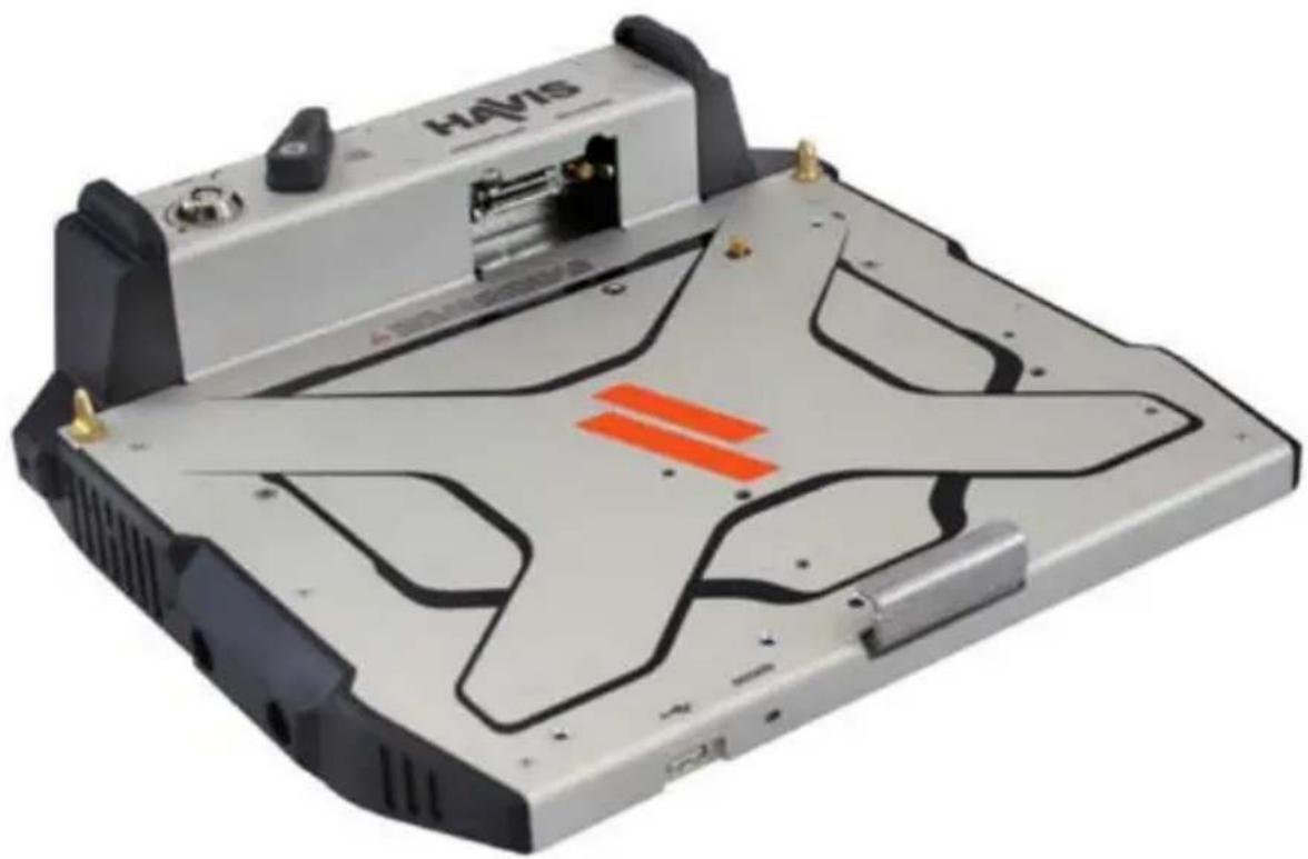
Exterior view of a Havis computer chassis with black plastic panels and orange warning stripe (no readable text or symbols)Havis is pleased to provide this Owner's Manual to aid in the proper installation and use of the DS-PAN-110 Series Docking Station for the Panasonic CF-30 & CF-31 laptop computers.
For questions regarding the set-up of your DS-PAN-110 Series Docking Station, please contact Havis at 1-800-524-9900 or visit www.havis.com/CF31 for additional product support and information.
This Owner's Manual applies to the following Product Numbers:
Port Replication Capability....3
Installation & Cable Management 4
Operation - Docking....7
Dock Indicator LED Diagnostics....8
Operation - Undoing 8
Zip Tie/Push Pin Information....9
Installation of Power Supply (LPS-101/LPS-104 - Optional).... 10
Precautions
- Do not place containers of liquid or metal objects on top of the Docking Station
- If a malfunction occurs, immediately unplug the Power Supply and remove the laptop
- Use only the specified Power Supply with this Docking Station
Recommended: Part # LPS-101 (90W) for CF-30, CF-31 Medium & Low Power Computers Recommended: Part # LPS-104 (120W) for CF-31 High Power Computers - Do not store the Docking Station where water, moisture, steam, dust, etc. are present
- Do not connect cables into ports other than what they are specified for
- Do not leave the Docking Station in a high temperature environment for a long period of time (greater than +60°C, 140°F)
Specifications
| Power Supply Input 15.6V DC-In |
| Dimensions* 12.4” (31.5 cm) W x 11.9” (30.2 cm) D x 4.0” (10.2 cm) H |
| Weight* 4.6 lbs (2.1 kg) |
| Operating Environment 5°C to 35°C (41°F to 95°F) |
| Storage Environment -20°C to 60°C (-4°F to 140°F) |
* DS-PAN-111
DECLARATION OF CONFORMITY FOR CE MARKING
Havis, Inc. declares that their DS-PAN-110 SERIES DOCKING STATIONS:
Are classified within the following EU Directives:
EU Electromagnetic Compatibility Directive 2004/108/EC
And further conform with the following EU Harmonized Standards:
EN 55022 (2006) + A1 2007, EN 55024 (1998) + A2: 2003
Dated: August 19, 2010
Position of signatory: Chief Information Officer / Chief Financial Officer
Name of signatory: Steve Ferraro
Signed:

Docking Station
Mounting Bracket

natural_image
Simple line drawing of a rectangular container with circular holes and labeled sections (no text or symbols)Hardware Kit
This Hardware Kit includes:
- Zip Ties/Push Pins (2)
- Keys (2)
- 1/4"-20 Screws (7)
- Zip Ties (6)
Tools required for installation:
- 5/32" Hex Drive (For securing 1/4"-20 Screws)

Port Replication Capability
Forward Exiting Connectivity

* NOTE
For CF-30 computers, WWAN pass-through can be controlled according to Wireless On/Off switch setting. For CF-31 computers, WWAN will always function as pass-through regardless of switch setting.
Rearward Exiting Connectivity (Optional Single or Dual Antenna)

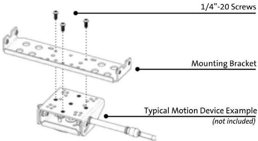
1). Install the Mounting Bracket to the Motion Device using (3) 1/4"-20 screws (Hardware Kit Item 3). Torque screws to 13.4Nm (120 in-lbs) ± 10%.
NOTE: Numerous hole patterns present in Mounting Bracket should accommodate most competitor's motion devices.
2). Orient the Docking Station in a position that is comfortable to work with.
3). Install all cables that are necessary for computing needs.
NOTE: If mounting Power Supply to Docking Station, go to Page 10 before completing Step 3
4). Use Zip Ties (Hardware Kit Item 4) to strain relieve cables to the Strain Relief Loops at front of Docking Station.
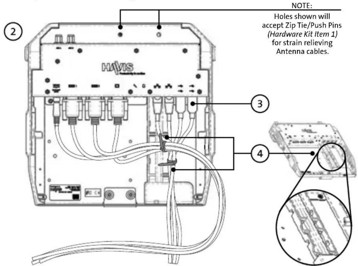
5). Gather all strain relieved cables into a single bundle and secure with Zip Ties to facilitate routing in later installation steps.
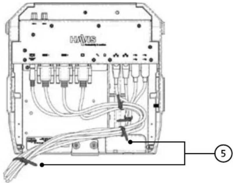
6). Lower the Docking Station onto the Mounting Bracket as shown, being cautious not to pinch the cable bundle. Secure with (4) 1/4"-20 screws (supplied). Torque screws to 13.4 Nm (120 in-lbs) ± 10%.
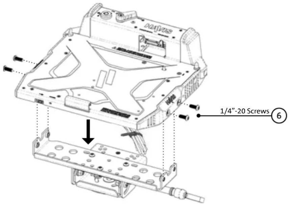
NOTE: It is recommended to use a drop of medium strength (blue) thread locking adhesive applied to the threads of all fasteners.
7). Tilt the Motion Device to a position allowing you access to the back side of docking station and route cables out the side as shown.

8). Route cable bundle and tie off to Mounting Bracket with Zip Tie (Hardware kit Item 4).
9). Create a service loop with cable bundle to ensure that no tension is on the connectors and to enable intended range of motion.
10). Tie off cables onto a stationary part of the mounting system.

11). Position Docking Station as desired for use inside mobile workspace.
CAUTION
- DO NOT MATE COMPUTER TO DOCKING STATION UNLESS COMPUTER'S DOCKING CONNECTOR ACCESS DOOR IS FULLY OPEN OR DAMAGE MAY RESULT.
- DO NOT FORCE LAPTOP ONTO DOCKING STATION. IF THERE IS RESISTANCE, CHECK ALIGNMENT OF COMPUTER ON DOCKING STATION.
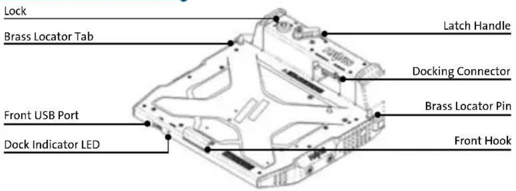
1). Ensure Docking Station is unlatched by positioning the Latch Handle to the "UNDOCK" position.
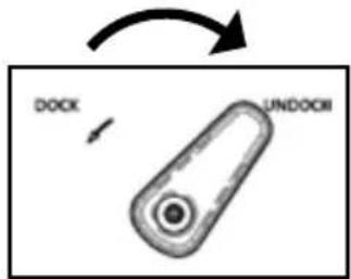
2). With rear of computer elevated, load front of computer into Docking Station by aligning Front Hook with the appropriate recess in the computer case.

natural_image
Technical line drawing of a mechanical component with an inset close-up view (no text or symbols)3). Lower back of computer onto Brass Locator Pins.

natural_image
Technical line drawing of a computer hard drive casing with mounting holes and ventilation slots (no text or symbols)4). Apply light downward pressure over rear of computer as indicated by Arrow A and rotate Latch Handle counter-clockwise to the "DOCK" position.

natural_image
Technical line drawing of a computer case with labeled component (A), no readable text or symbols present
5). For theft deterrence, secure computer by locking Docking Station with supplied key.

6). Power on computer. The Dock Indicator LED will light up green to indicate proper system function.

DOCK INDICATOR LED DIAGNOSTICS:
GREEN: Computer docked, all ports ready for use.
ORANGE: USB and LAN ports are not functioning.
RED: Computer is not supported or a connection is not made.
RED (Blinking): Firmware error has occurred.
NOT LIT: Computer is not installed, is turned off, or in standby or sleep mode.
Operation - Undocking
1). If previously locked, unlock Docking Station using supplied key.

2). Rotate Latch Handle clockwise to the "UNDOCK" position.

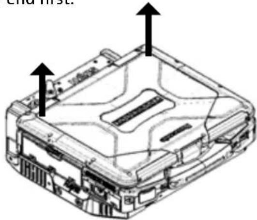
3). Once unlatched grab both sides of computer and carefully lift out of Docking Station, rear end first.
Zip Tie/Push Pin Information
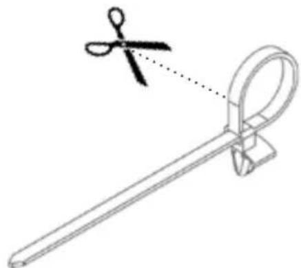
1). In the event that a strain relieved cable needs to be removed or replaced, do not attempt to remove entire Zip Tie/Push Pin. Cut Zip Tie as shown, taking care to not damage the cables.
natural_image
Line drawing of a pair of scissors cutting a metal tool (no text or symbols)2). Pull the cut Zip Tie through the Push Pin housing. Trim excess so sharp edge does not damage reinstalled cables.

3). Insert a new Zip Tie into the Push Pin housing and strain relieve cables.

natural_image
Simple line drawing of a long rod with a black arrow pointing downward (no text or symbols)NOTE: Refer to Page 1 to ensure that you have the appropriate Power Supply for your Specific computer model.
1). Power off computer and ensure all cables are disconnected from computer.
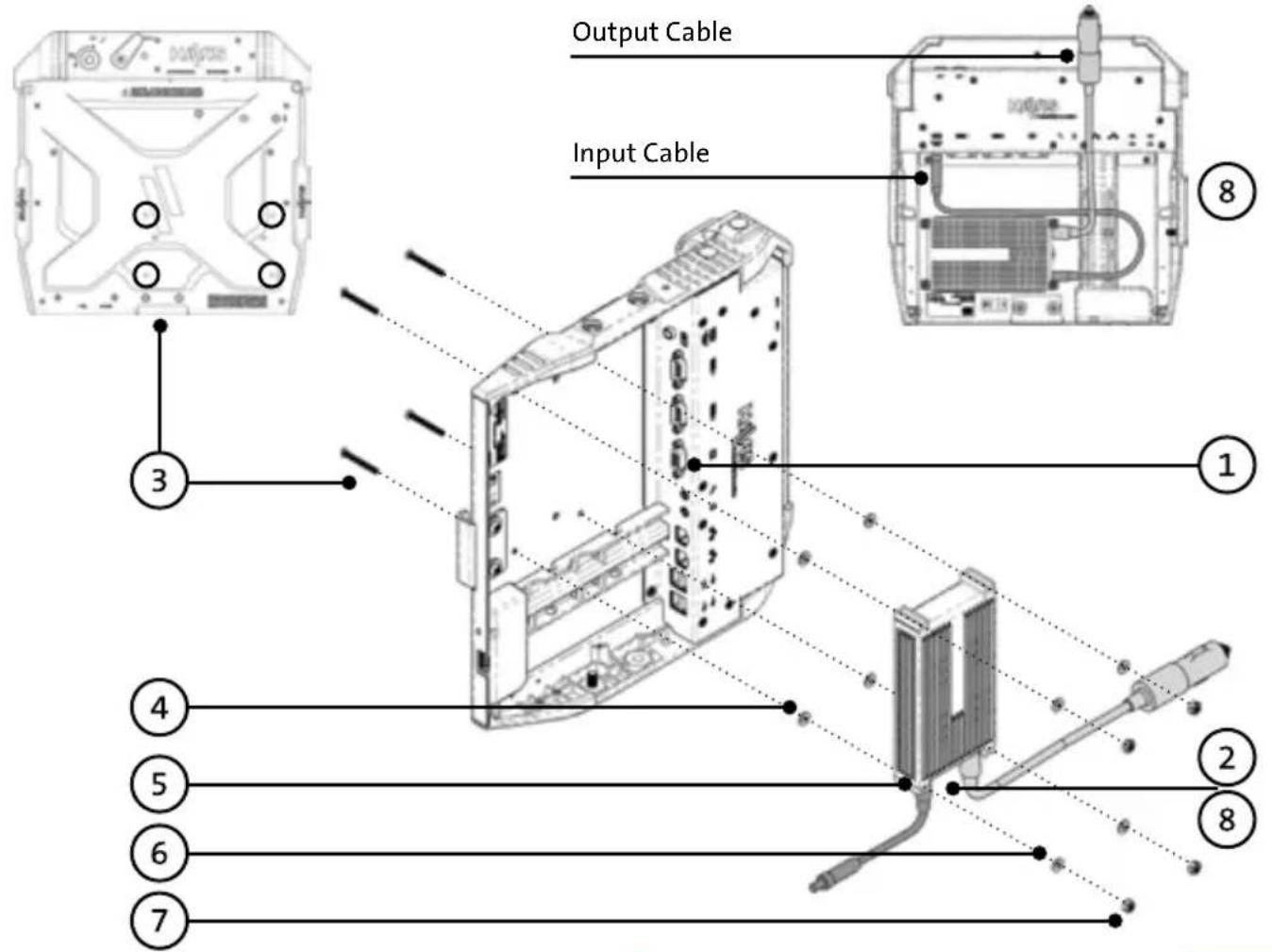
2). Plug in both input and output cables (supplied with LPS-101/LPS-104) into the Power Supply brick.
3). With the Docking Station right side up, drop (4) #6-32 screws (supplied with LPS-101/LPS-104) through the holes in Docking Station as shown.
4). While supporting the (4) #6-32 screws, flip the Docking Station upside down and place (1) flat washer over each of the (4) #6-32 screws.
5). Place the Power Supply brick over the (4) #6-32 screws ensuring that the screws pass through all of the bosses on the Power Supply brick and the cables are pointing in the direction shown.
6). Place the remaining (4) flat washers over each of the #6-32 screws and hand start a #6-32 locking nut onto each of the screws.
7). Torque all (4) #6-32 locking nuts to 0.9 Nm (8.0 in-lbs) ±10% ensuring that the #6-32 screws stayed properly aligned with the bosses of the Power Supply brick.
8). Route the Power Supply output cable as shown and secure connector to power input port on Docking Station. Be sure to coil and strain relieve excess cabling.
9). Return to Installation & Cable Management Step #3 on Page 4.
Related Products
Havis offers a wide variety of accessory products for use with the DS-PAN-110 Series Docking Station.
For more information or to order please visit www.havis.com.

natural_image
Black electronic device with coiled cable and rectangular connector (no visible text or symbols)LPS-104
120W Power Supply
External power supply and cable for Panasonic CF-31
Toughbooks with cigarette lighter adaptor.
natural_image
Simple black mechanical component resembling a lever or fulcrum, isolated on white background (no text or symbols)DS-DA-409
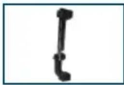
Screen Stiffener
Secure your laptop screen to prevent excess wear and reduce vibration while in use.

natural_image
Exterior view of a gray electronic component with a black internal structure (no visible text or symbols)DS-DA-601
Rugged Communications Hub
Rugged USB/Ethernet hub makes adding peripherals to your mobile workspace easy and safe.

natural_image
Simple line drawing of a pen-like object (no text or symbols)DS-DA-102
USB Powered Keyboard Light
Soft red LED light illuminates the laptop keyboard for night viewing.

natural_image
Black metal bracket with two mounting holes (no text or symbols visible)DS-DA-207
Card Reader Mounting Bracket
Mount an E-Seek Model 250 card reader to the side of the Docking Station.
(Bracket can be customized for other Card Reader Models)
Interactive Online Catalog
This new and exciting interactive catalog is an easy to use, full color, online version of our printed catalog.
Visit www.haviscatalog.com for direct access to the Interactive Catalog!

Havis, Inc.
75 Jacksonville Road, PO Box 2099
Warminster, PA 18974
47801 Anchor Court
Plymouth, MI 48170
www.havis.com 1-800-524-9900



- Havis Rugged Mobile Docking Station
- For Panasonic CF-30& CF-31 Toughbooks
- Owner's Manual
- Precautions
- Specifications
- DECLARATION OF CONFORMITY FOR CE MARKING
- Docking Station
- Mounting Bracket
- Hardware Kit
- This Hardware Kit includes:
- Tools required for installation:
- Port Replication Capability
- Forward Exiting Connectivity
- Rearward Exiting Connectivity (Optional Single or Dual Antenna)
- CAUTION
- DOCK INDICATOR LED DIAGNOSTICS:
- Operation - Undocking
- Zip Tie/Push Pin Information
- Related Products
- Interactive Online Catalog
Brand : PANASONIC
Model : DS-PAN-112-2
Category : Computer accessory