PAC15 - Air Conditioning Andrews - Free user manual and instructions
Find the device manual for free PAC15 Andrews in PDF.


| Product Type | Portable Air Conditioner |
| Brand | Andrews |
| Model | PAC15 |
| Cooling Capacity | 15000 BTU/h |
| Power Consumption | 1500 W |
| Voltage | 220-240 V / 50 Hz |
| Dimensions (W x D x H) | 30 x 35 x 70 cm |
| Weight | 20 kg |
| Airflow | 300 m³/h |
| Noise Level | 55 dB |
| Refrigerant | R410A |
| Modes | Cool, Fan, Dehumidify |
| Controls | Remote control + touch panel |
| Timer | 24-hour programmable |
| Sleep Mode | Yes |
| Auto Swing | Yes |
| Installation | Window kit included |
| Filter Cleaning | Every 2 weeks |
| Safety Features | Overload protection, auto restart |
| Spare Parts | Filter, remote control |
Frequently Asked Questions - PAC15 Andrews
User questions about PAC15 Andrews
0 question about this device. Answer the ones you know or ask your own.
Ask a new question about this device
Download the instructions for your Air Conditioning in PDF format for free! Find your manual PAC15 - Andrews and take your electronic device back in hand. On this page are published all the documents necessary for the use of your device. PAC15 by Andrews.
USER MANUAL PAC15 Andrews
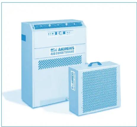
PAC15 Portable Air Conditioning
natural_image
Two blue industrial air conditioning machines, one large and one smaller, displayed against a white background (no visible text or symbols on the devices themselves).Operating Instructions & Safety Guide

General Safety
Keep children and animals away from air conditioning units. Never leave them alone in a room where the units in use.
This equipment should only be used by a competent person who has read and understood these instructions.
Never operate this equipment if you are ill, feeling tired or under the influence of alcohol or drugs.
- Keep the Air Conditioning vents clear of all obstructions.
Never put anything on top of the unit or block the air outlets.
Make sure equipment is switched off and unplugged after use.
Never leave switched on or unattended.
Do not use the unit where sunlight is shining directly onto it.
Check condition of equipment before use. If unit is showing signs of damage contact your supplier immediately.
Electrical Safety
This unit requires a 230 volt electrical supply. It plugs into a standard BS1363 domestic socket.
Always inspect plugs and leads for damage before plugging into the supply - DO NOT USE IF ANY DAMAGE IS FOUND
Ensure cables are run as not to cause a hazard.
If an extension lead is used, ensure it is of the correct standard, and fully uncoiled when being used.
Do not lay electrical cables in wet / damp areas.
Do not move equipment whilst operating.
Do not pull equipment by its cable.
It is recommended that electrical equipment is used via a suitable RCD.
Machine not working?
ONLY A COMPETENT ELECTRICIAN SHOULD ATTEMPT TO RECTIFY ELECTRICAL SUPPLY PROBLEMS. DO NOT REMOVE ANY PANELS FROM THE MACHINE.

natural_image
Person installing or adjusting a device panel in a blue-tinted indoor setting (no visible text or symbols)| Problem Likely Cause Solution | ||
| No air flow from the room unit | Red 'MAINS' light off Tum on electricity and/or check mains supply fuse | |
| No air flow from the room unit | Red 'MAINS' light on. White 'DEFROST' light on | Machine is in defrost mode, do not adjust anything, machine will revert to normal run after 10 mins |
| Insufficient air flow from the room unit | Blocked air filter Clean filter | |
| No cooling Green 'COOLING' light off | Revolve thermostat knob fully anti-clockwise to '1'. Wait 10 minutes for time delay on start-up. | |
| No cooling Amber 'ATTENTION' light illuminated. High pressure trip. | Press '+' button to re-set and check for: Lack of water flow...kinked hoses? Shortage of water..... top up. External heat exchanger unit mounted in very high temperature? Water frozen? Add glycol (33%) External heat exchanger coil blocked with dirt.... clean Air cooled units.... lack of air flow from exhaust.... kinked or blocked duct, duct too long. | |
| No cooling Amber 'ATTENTION' light illuminated. Low pressure trip. | Press '-' button to re-set and check for: No air flow, blocked filter? Evaporator blocked with ice. Very low air temperature? | |
| No cooling Amber 'ATTENTION' light illuminated. High level condensate trip. | Condensate pump not reducing water level. Kink in condensate tube between room unit and external heat exchanger? Leak inside room unit. Pump filter inside room unit blocked. Condensate tube frozen | |
Routine Maintenance
The air filter must be kept clean, never allow to become choked with dust or dirt. If allowed to do so, the performance of the unit will become impaired, resulting in loss of air flow, freezing up the evaporator coil and possible component damage.
To access the filter, lift out the return air grille on the front face of the unit (fig. 4). On refitting the filter ensure that it is correctly positioned covering the whole face of the grille.
The filter (see fig. 4) can be washed in warm, soapy water, rinsed and shaken dry before replacement. Frequency of cleaning depends upon application and can
Operating Instructions - PAC15
only be determined by the user. However, you should never allow more than two months to elapse between cleaning. The probable life of the filter will be about one year and spares are available from the supplier of the unit itself. Failure to have filter fitted during operation will cause serious damage.
The refrigeration circuit inside the room unit is fitted with a HIGH and a LOW pressure sensing switch. They are both manually re-settable. Necessary access is provided either via the lower front panel or through the control console. A pencil or screwdriver with gentle pressure on the knob behind is all that is required to re-set.
HOWEVER, DO NOT ATTEMPT TO RE-SET WITHOUT FIRST DISCOVERING WHY THE TRIP OCCURRED IN THE FIRST PLACE
Installation
USE THE CHAINS PROVIDED TO SUPPORT THE HEAT EXCHANGER - IT WOULD BE HIGHLY DANGEROUS TO SUPPORT THE HEAT EXCHANGER BY MEANS OF THE FLEXIBLE LINES ALONE.
In operation the room unit is constantly condensing water vapour out of the atmosphere (reducing relative humidity). This water has to be drained away, An automatic condensate pump is fitted inside the room unit. The flexible hose outlet from the condensate pump runs to the outside, inside the flexible sheath and the condensate is deposited in the base of the heat exchanger, but please remember that there will also be a degree of dripping through the base of the heat exchanger
HAVE GREAT REGARD FOR THIS CHARACTERISTIC WHEN POSITIONING THE EXTERNAL HEAT EXCHANGER
The flexible water pipes should be routed so as to avoid any possibility of kinking or unnecessary restrictions to the flow of water inside. Also, remember that plastic and rubber becomes much more flexible when warm and. as a result, much more susceptible to distortion.
Machine Link-Up
Ensure the mains supply lead to the room unit is disconnected, A 5m (extendable to 30m) line set to connect all services between the room unit and the external heat exchanger will have been supplied. The water pipe connections are by means of 'quick connect couplers'. These are simple 'push-on' connectors which, when disconnected (after pulling back sprung loaded locking ring), re-seal the water system on either side. The complete system will have been filled with the necessary amount of water/ antifreeze prior to its arrival on site. A water proof 3 pin quick connect electrical coupler (push fit with screw lock ring, hand tight only), and condensate drain pipe coupler 6mm clear polythene (push fit), should also be connected. Having made the couplings, the system is operational immediately.
Room Water Levels
The water system in the room unit will be to the correct level when delivered.
However if for some reason the level has fallen, antifreeze (33%) and water will have to be added. The header tank filler and level indication is located to the rear of the room unit and can be accessed by removing the two screws holding the security plate over the filter tank cap. Ensure the machine is running in cooling mode before removing the header tank cap, and as with all the pressure caps, remove slowly. It is recommended that a mixture, by volume, of one part antifreeze to two parts water is utilised, this will prevent freezing down to an external temperature of -20C/-5F. The approximate total volume of both the available systems, large or small room unit with external heat exchanger and lines is as follows.
This unit MUST be transported and operated in the upright position at all times.
Electrical Supply
WARNING! As standard this unit requires a 13 amp fused electrical supply rated at 230 volts. -1N, 50Hz.
The unit will operate from a standard 13A wall socket. The size of any extension cable that may be 2-5mm2 minimum up to a maximum length of 10 metres. For longer lengths 4mm^2 cable must be used. If the cable is on a 'cable drum' then ensure that it is completely unwound; serious complications will occur otherwise.
System Description
The system comprises a room unit cooling section, an external heat exchanger and the two are interconnected by means of a flow and return water pipe and an electrical supply to the heat exchanger fan. The room unit is fitted with an automatic condensate disposal pump which discharges the condensate via a small plastic pipe into the base of the external heat exchanger and all interconnecting pipes and electrics are enclosed in a flexible plastic sheath. In addition, both ends of each pipe are fitted with 'quick connect' couplings that open on coupling but reseal to become water tight on disconnect.
Airflow
The angled air outlets at the top of the room unit are fitted with air grilles that allow the angle of air outlet to be adjusted vertically and horizontally and, in conjunction with the fan speed control switch, the air velocity and direction can be carefully set up to obtain maximum coverage of the area being cooled without causing drafts. Care should be taken to avoid outlet air being obstructed as this will cause the air to 'eddy' around the unit resulting in recirculation and short/inaccurate cycling of the machine. Ideally, cold air should be directed to create a 'blanket' all across the ceiling area allowing natural convection to drop the air over the whole area at very low velocity.
Siting
Ideally, the room unit should be positioned equidistant along he shortest wall in the room blowing down the length of the room. Of there is more than one unit in the same area, then they would normally be positioned side by side, and equidistant along the long wall, all pointing in the same direction. Sometimes it may be
necessary to position units around the perimeter of an area but, in this case, great care should be taken to avoid one unit blowing cold air straight into another which will adversely affect the machine operation. Good and correct air flow is, perhaps, the single most important aspect of satisfactory applying portable air conditioners. If in doubt seek the advice of your supplier.
The heat exchanger must stand external to the area being cooled and, preferably, in the outside atmosphere. It can stand freely on a flat surface or may be hung in the upright position, from a window-sill, balcony etc (see fig. 1).
flowchart
graph TD
    A["MAINS LIGHT (RED)"] --> B["COOLING LIGHT (GREEN)"]
    B --> C["FAN DLYL POSITION"]
    C --> D["MOOD SWITCH"]
    D --> E["FAN SPEED SWITCH"]
    E --> F["FAN SPEED HIGH"]
    F --> G["ATTENTION LIGHTS (AMBER)"]
    G --> H["FAN SPEED LOW"]
    I["DEFROST LIGHT (WHITE)"] --> J["COOLING POSITION"]
    J --> K["MODE SWITCH"]
    K --> L["FAN SPEED SWITCH"]
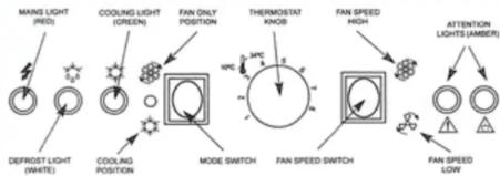
- Revolve thermostat knob fully
CLOCKWISE to the number '8' position - Plug in the room unit mains cable, and switch on the electricity, red mains light will illuminate.
- Select 'Fan Only' with the mode switch. The fan will start.
-
Select 'Fan Speed' with the fan speed switch, high or low depending on air velocity required.
-
Select 'Cooling' with the mode switch, and revolve the thermostat knob fully ANTI-CLOCKWISE to he number '1' position. If fitted the external heat exchanger fan and the water pump in the room unit will start. After a delay of 10 mins the green 'Cooling' light will illuminate and the machine will proceed to cool the air.
Monitor the room temperature and when it has reduced to the desired level, very slowly revolve the thermostat knob back, clockwise until the green 'Cooling' light goes out. The room unit will now control the room temperature cooling automatically at this setting.


Brand : Andrews
Model : PAC15
Category : Air Conditioning