PD-2800UN - Customer display Posiflex - Free user manual and instructions
Find the device manual for free PD-2800UN Posiflex in PDF.


| Product Type | Customer Pole Display |
| Display Technology | Vacuum Fluorescent Display (VFD) |
| Number of Rows | 2 |
| Characters per Row | 20 |
| Dot Matrix | 5 x 7 dots |
| Digit Height | 9.03 mm |
| Digit Width | 5.25 mm |
| Display Color | Blue or Green |
| Total Height | 265 - 395 mm (adjustable) |
| Total Width | 200 mm |
| Total Depth | 116 mm |
| Display Head Dimensions (H x W x D) | 58.5 x 200 x 56.5 mm |
| Weight | ~1.2 kg (estimated based on typical pole displays) |
| Power Supply | +5 VDC, 1 A via USB interface from POS terminal |
| Interface | USB with RS-232 emulation |
| Command Emulation Modes | ADM, Aedex, Epson, Futaba, Noritake, UTC (selectable via DIP switch) |
| Code Pages | 12 code pages of 128 characters each |
| International Character Sets | 12 character sets of 12 characters each |
| Software Support | OPOS 1.8, JPOS, UPOS, WEPOS ready |
| Mounting Options | Standalone pole with adjustable height, rear base mount for Posiflex Gen. 1 base, screw holes for flat surface, Velcro support |
| Operating Temperature | 0°C to +40°C |
| Storage Temperature | -20°C to +70°C |
| Operating Humidity | 20% to 85% (non-condensing) |
| Storage Humidity | 5% to 90% (non-condensing) |
| Case Color | Black or Ivory |
Frequently Asked Questions - PD-2800UN Posiflex
User questions about PD-2800UN Posiflex
0 question about this device. Answer the ones you know or ask your own.
Ask a new question about this device
Download the instructions for your Customer display in PDF format for free! Find your manual PD-2800UN - Posiflex and take your electronic device back in hand. On this page are published all the documents necessary for the use of your device. PD-2800UN by Posiflex.
USER MANUAL PD-2800UN Posiflex
PD – 2800/320 Series User's Manual
Rev. A0
FCC Notes:
This equipment generates, uses, and can radiate radio frequency energy and, if not installed and used in accordance with the instructions manual, may cause interference to radio communications. It has been tested and found to comply with limits for a Class A digital device pursuant to subpart J of Part 15 of FCC Rules, which are designed to provide reasonable protection against interference when operated in a commercial environment. Operation of this equipment in a residential area is likely to cause interference in which case the user at his own expense will be required to take whatever measures to correct the interference.
Warranty Limits:
Warranty terminates automatically when any person other than the authorized technicians opens the machine. The user should consult his/her dealer for the problem happened. Warranty voids if the user does not follow the instructions in application of this merchandise. The manufacturer is by no means responsible for any damage or hazard caused by improper application.
About This Manual:
Posiflex has made every effort for the accuracy of the content in this manual. However, Posiflex will assume no liability for any technical inaccuracies or editorial or other errors or omissions contained herein, nor for direct, indirect, incidental, consequential or otherwise damages, including without limitation loss of data or profits, resulting from the furnishing, performance, or use of this material.
This information is provided “as is” and Posiflex Technology, Inc. expressly disclaims any warranties, expressed, implied or statutory, including without limitation implied warranties of merchantability or fitness for particular purpose, good title and against infringement.
The information in this manual contains only essential hardware concerns for general user and is subject to change without notice. Posiflex reserves the right to alter product designs, layouts or drivers without notification. The system integrator shall provide applicative notices and arrangement for special options utilizing this product. The user may find the most up to date information of the hardware from web sites: http://www.posiflex.com or http://www.posiflex.com.tw
All data should be backed-up prior to the installation of any drive unit or storage peripheral. Posiflex will not be responsible for any loss of data resulting from the use, disuse or misuse of this or any other Posiflex product.
All rights are strictly reserved. No part of this documentation may be reproduced, stored in a retrieval system, or transmitted in any form or by any means, electronic, mechanical, photocopying, or otherwise, without prior express written consent from Posiflex Inc. the publisher of this documentation.
© Copyright Posiflex Technology, Inc. 2011
All brand and product names and trademarks are the property of their respective holders.
P/N: 19460902020

About PD-2800 / 320
The PD-2800/320 is a standalone pole mount customer display designed for discrete POS applications. It delivered in separate carton for HT / PB / KS / TP / FT / XP series and should be installing refer to the instruction which in this manual.
FEATURES
- PD-2800 is a bright two-line VFD (vacuum fluorescent display) display with 20 characters per line and combines with green or blue filter.
- PD-320 is a two-line LCD display with 20 characters per line
- Stand along customer pole display for Posiflex POS terminals.
- Easy-to-read large characters (9.03 mm × 5.25 mm for PD-2800, 6.0 mm × 9.66 mm for PD-320).
● Longlife and double free design.
● Various command emulation modes selectable by DIP switch.
● Support 12 Code Pages of 128 characters each on PD-2800.
● Support 12 international character sets of 12 characters each on PD-2800. - USB interface with RS-232 emulation for numerous applications without modify the software.
● UPOS 1.8 and is WEPOS ready supported. - Euro dollar sign supported in USA/European font table.
- Selectable command emulation modes including PST and EPSON command emulation modes for PD-320.
- Composed of several members in the family for versatile applications as tabulated below.
INSTALLATION GUIDES
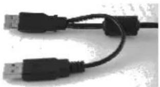
The power of PD-2800/320 is supported through USB connection. For PD-2800/320 customer display, there are two USB connector needs to link to the host system. Please confirm that both of these two USB connectors connect to terminal in order to support the power and data transmission.
natural_image
Close-up of two USB cables with black connectors (no text or symbols visible)INSTALLATION FOR STAND ALONG MODEL
For this type mechanical design of standalone customer pole display, it can operate straight away and no needs to assemble with any other host system. Nevertheless, it also can fix on the counter or any place when it needs to be fixed. Following pictures A to D will describe such as how to adjust the height of the pole and how to fasten the PD-2800/320 in a flat surface.
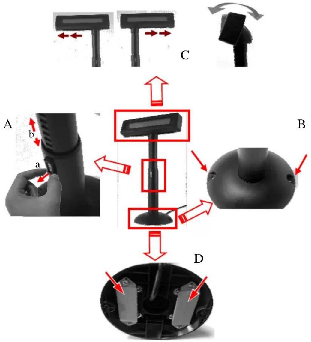
Picture A is going to describe how to adjust the height of customer displays:
a). Please hold the compression lock by using thumb and index finger and pull out the lock.
b). Please use another hand to hold the tube and extend to higher or lower of display's height. After adjust to a satisfied height, please push back the compress lock to fix the tube.
Note: Please align the compress lock and the grooves in order to fix the height of customer display.
Picture B is going to show how to screw PD-2800/320 in a flat surface. In the base stand of PD-2800/320, there are two screws holes for user to fix the customer display. Please choose a flat surface to fix the customer display in order to keep the PD-2800/320 stable. (The screws are come with PD-2800/320 and in the carton)
Picture C, the display head of PD-2800/320 can move as horizontal direction to right or left, as well as front-rear adjustable degree from 15^ or 23^
Picture D, there are two plates in the bottom of customer display which can use for Velcro and provides more stable without screws fixed. (The Velcros are come with PD-2800/320 and in the carton)
INSTALLATION FOR REAR BASE MOUNT MODEL
For this type mechanical design of rear base mount pole display, it needs to assemble with any a host system. For base stand of host system, it only suit for Posiflex Gen. 1 ^st base and which will show in the following steps. Please follow the instruction to assemble this customer pole display.
natural_image
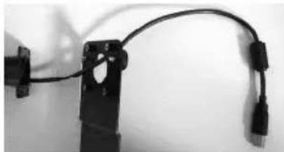
Close-up of a black cable with two connectors, no visible text or symbolsStep 1: Please pass the connecting cable through the hole which in the base metal plate.
natural_image
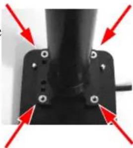
Close-up of a black mechanical component with four red arrows pointing to its mounting holes (no text or symbols visible)Step 2: Hold the display with pole and aim to the base metal plate as well as let these four screw tubes join these holes which in the end of pole. Please notice that the customer display face to the short side of metal plate.
Step 3: Turn the pole display and base stand upside-down before combination. Pass the cable through base stand and connect to the host system.
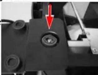
Step 4: Aim the hole which on the metal plate to the rubber foot on the Gen. 1^st base stand's bottom as show in the right picture. Hold the system with customer display and turn them upside down to the regular position.
natural_image
Close-up of a mechanical component with a red arrow pointing to a circular feature (no visible text or symbols)PD-2800 COMMAND EMULATION MODE SETUP
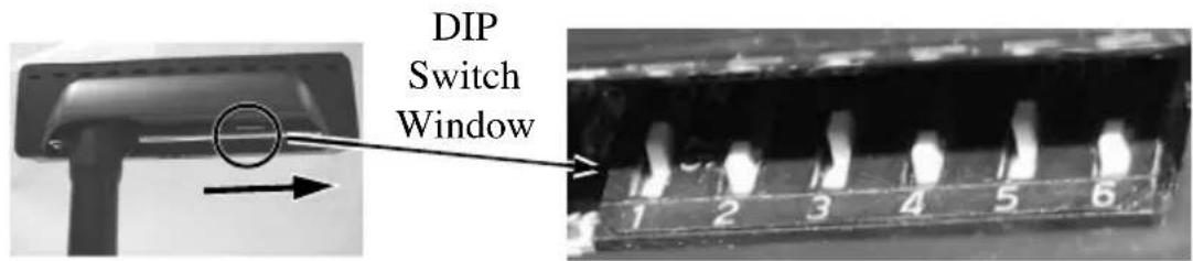
Now please check the back of PD-2800 display head as in the picture below. There is a small DIP switch window in the right side of display head. Slide the display head to right then you can find 6 positions of DIP switches in this window. Please use a tiny stick to adjust for the appropriate command mode used by the application program according to below table. Switch position counts from left to right and “ON” means pushed up as indicated in the right part picture below.
| Switch Position | Command Mode | |||||
| 1 2 | 3 4 5 | 6 | ||||
| ON | OFF | OFF | ON | OFF | OFF | ADM |
| ON | OFF | ON | ON | OFF | OFF | Aedex |
| ON | OFF | ON | OFF | OFF | OFF | Epson |
| ON | OFF | OFF | ON | ON | OFF | Futaba |
| ON | OFF | ON | OFF | ON | OFF | Noritake |
| ON | OFF | ON | ON | ON | OFF | UTC |
The default command mode is set to Noritake mode for normal delivery. Please change it to Epson mode if OPOS or UPOS driver is used for the application program.
USING THE PD-2800 COMMAND MODE SELECTION GUIDE
The below table provides some comparison for selection on command mode to be used in the application program if it is not yet determined.
| Mode ADM Aedex | Epson Futaba | Noritake | UTC | ||
| Cursor N.A. N.A. Invisible | Blinking Block | Blinking Block | Blinking Block (DP) | ||
| Default mode N.A. N.A. Over/W | V. scroll | Over/W | PT | ||
| User defined font N.A. | N.A. 2 | chars | N.A. 2 chars | 2 chars (PT) | |
| Brightness control NO | NO YES | S YES YES YES | (DP) | ||
| Leading code change | NO YES | NO YES YES YES | YES (PT) | ||
| Code page select NO | NO YES | YES YES YES | |||
| Auto scroll message | NO NO | NO YES YES YES | (PT) | ||
| Timer clock NO NO | YES NO | NO YES (PT) | |||
DRIVER INSTALLATION
The OPOS (OLE POS) driver or the JPOS (Java POS) driver would be required for OPOS or JPOS programs and the PD-2800/320 would have to be set into “Epson” command mode. These drivers are available from our web page:
http://www.posiflex.com.tw/Download%20list.asp?Status=1&Series_Name=UPOS&Model_Name=OPOS and execute the file “SETUP.EXE” to install the OPOS Control Manager. To add the customer display under OPOS control please set in OPOS Control Manager device name “PD2x-Line Display” in the top row. Select “USB” in third row as in the right sample picture below. Please visit our web site and find the driver from the class “PD23_26U”. The guidance for each function call in the library “USBPD.dll” is covered in the “ReadMe” file in that class.
For more information about driver installation, please contact your local dealer or authorized technician.
SPECIFICATION
OPTICAL
| Number of digits | 20 digits/row, 2 rows |
| Dot matrix | 5 X 7 dots |
| Digit height | 9.03 mm (PD-2800) |
| 9.66 mm (PD-320) | |
| Digit width | 5.25 mm (PD-2800) |
| 6.0 mm (PD-320) | |
| Display color | Blue or Green (for PD-2800) |
| Dark Blue character with yellow background (for PD-320) |
MECHANICAL
Total Height (PD-2800/320) 395\~265 mm
Total Width (PD-2800/320) 200 mm
Total Depth (PD-2800/320) 116 mm
Display Head Height 58.5 mm
Display Head Width 200 mm
Display Head Depth 56.5 mm
Case color Black or Ivory
ELECTRICAL
Power from interface port of POS terminal: +5VDC 1A
ENVIRONMENTAL
Operating temperature 0^ to +40^
Storage temperature -20° to +70°C
Operating humidity 20% to 85%, non-condensing
Storage humidity 5% to 90%, non-condensing
WARNING: If the user opens the pole display housing to make any modification, all product warranty will be void.
NOTE: Please refer to Posiflex Product Information CD or DVD or visit our web http://www/posiflex.com.tw for further information when needed.
- PD – 2800/320 Series User's Manual
- FCC Notes:
- Warranty Limits:
- About This Manual:
- © Copyright Posiflex Technology, Inc. 2011
- About PD-2800 / 320
- FEATURES
- INSTALLATION GUIDES
- INSTALLATION FOR STAND ALONG MODEL
- INSTALLATION FOR REAR BASE MOUNT MODEL
- PD-2800 COMMAND EMULATION MODE SETUP
- USING THE PD-2800 COMMAND MODE SELECTION GUIDE
- DRIVER INSTALLATION
- SPECIFICATION
- MECHANICAL
- ELECTRICAL
- ENVIRONMENTAL
Brand : Posiflex
Model : PD-2800UN
Category : Customer display