
AP150WN1X1OG - Access Point StarTech.com - Free user manual and instructions
Find the device manual for free AP150WN1X1OG StarTech.com in PDF.


| Product Type | Access Point |
| Wireless Standard | IEEE 802.11b/g/n |
| Wireless Speed | Up to 150 Mbps |
| Frequency Band | 2.4 GHz |
| Interface | 1 x 10/100 Mbps Ethernet (RJ-45) |
| Power | Power over Ethernet (PoE) 802.3af or DC 5V (adapter not included) |
| Security | WEP, WPA/WPA2, WPA-PSK/WPA2-PSK |
| Mounting | Wall-mountable with included bracket |
| Dimensions | 160 x 120 x 30 mm (6.3 x 4.7 x 1.2 in) |
| Weight | 200 g (7.05 oz) |
| Operating Temperature | 0°C to 40°C (32°F to 104°F) |
| Storage Temperature | -20°C to 60°C (-4°F to 140°F) |
| Humidity | 10% – 90% non-condensing |
| Certifications | FCC, CE |
| Warranty | 2 years |
| Package Contents | Access point, mounting bracket, quick start guide |
| Maintenance | Clean with a dry, soft cloth; avoid liquids. |
| LED Indicators | Power, LAN, WLAN |
| Antenna | Internal antenna |
Frequently Asked Questions - AP150WN1X1OG StarTech.com
User questions about AP150WN1X1OG StarTech.com
0 question about this device. Answer the ones you know or ask your own.
Ask a new question about this device
Download the instructions for your Access Point in PDF format for free! Find your manual AP150WN1X1OG - StarTech.com and take your electronic device back in hand. On this page are published all the documents necessary for the use of your device. AP150WN1X1OG by StarTech.com.
USER MANUAL AP150WN1X1OG StarTech.com
Outdoor 150Mbps Wireless N Access Point - 1T1R 2.4GHz
AP150WN1X1OD / AP150WN1X1OE / AP150WN1X1OG
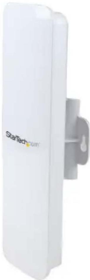
natural_image
White wireless router with 'StarTech.com' branding, mounted on a gray wall (no additional text or symbols visible)*actual product may vary from photos
For the most up-to-date information, please visit: www.startech.com
FCC Compliance Statement
This equipment has been tested and found to comply with the limits for a Class B digital device, pursuant to part 15 of the FCC Rules. These limits are designed to provide reasonable protection against harmful interference in a residential installation. This equipment generates, uses and can radiate radio frequency energy and, if not installed and used in accordance with the instructions, may cause harmful interference to radio communications. However, there is no guarantee that interference will not occur in a particular installation. If this equipment does cause harmful interference to radio or television reception, which can be determined by turning the equipment off and on, the user is encouraged to try to correct the interference by one or more of the following measures:
- Reorient or relocate the receiving antenna.
- Increase the separation between the equipment and receiver.
- Connect the equipment into an outlet on a circuit different from that to which the receiver is connected.
- Consult the dealer or an experienced radio/TV technician for help.
This Class B digital apparatus complies with Canadian ICES-003.
This device complies with Industry Canada licence-exempt RSS standard(s).
Operation is subject to the following two conditions:
(1) This device may not cause interference, and
(2) This device must accept any interference, including interference that may cause undesired operation of the device.
IC Radiation Exposure Statement:
This equipment complies with IC RSS-102 radiation exposure limit set forth for an uncontrolled environment. This equipment should be installed and operated with minimum distance 20cm between the radiator and your body.
Use of Trademarks, Registered Trademarks, and other Protected Names and Symbols
This manual may make reference to trademarks, registered trademarks, and other protected names and/or symbols of third-party companies not related in any way to StarTech.com. Where they occur these references are for illustrative purposes only and do not represent an endorsement of a product or service by StarTech.com, or an endorsement of the product(s) to which this manual applies by the third-party company in question. Regardless of any direct acknowledgement elsewhere in the body of this document, StarTech.com hereby acknowledges that all trademarks, registered trademarks, service marks, and other protected names and/or symbols contained in this manual and related documents are the property of their respective holders.
Important Notice
This product MUST be installed by a professional installer who is familiar with local building and safety regulations, where appropriate, and is licensed by applicable authorities. The professional installer is responsible for making sure grounding is available and that it meets the relevant local and national electrical codes. Failure to employ a professional installer may render the product warranty void and it may also expose the end user or service provider to legal and financial liabilities. StarTech.com expressly disclaims any and all liabilities for injury, damage, or violation of regulations due to improper installation of outdoor units or antennas.
Always remember to protect the AP by installing grounding lines as it is necessary to protect your outdoor installations from lightning strikes and the build-up of static electricity. The AP must be grounded properly before powering up, as direct grounding of an outdoor AP is critical and must be done correctly to protect your networks from harsh outdoor environments and destructive ESD surge.
CAUTION: Be sure that earth grounding is available and that it meets local and national electrical codes. If in doubt always consult with a qualified electrician to make sure the outdoor installation is properly grounded. For additional lightning protection, lightning rods, lightning arrestors or RJ45 surge protectors may be used to compliment the installation.
Table of Contents
Product Diagram....1
Rear View....1
Introduction......2
Packaging Contents 2
System Requirements....2
Connection Ports....3
LED Indicators....4
Installation 4
Preparing Your Site 4
Hardware Installation....5
Operation 6
Advanced Configuration 8
Wireless Settings 9
Smart Features 14
IP Settings 16
Management Settings....17
Password Settings (recommended) 18
Specifications....19
Technical Support 20
Warranty Information......20
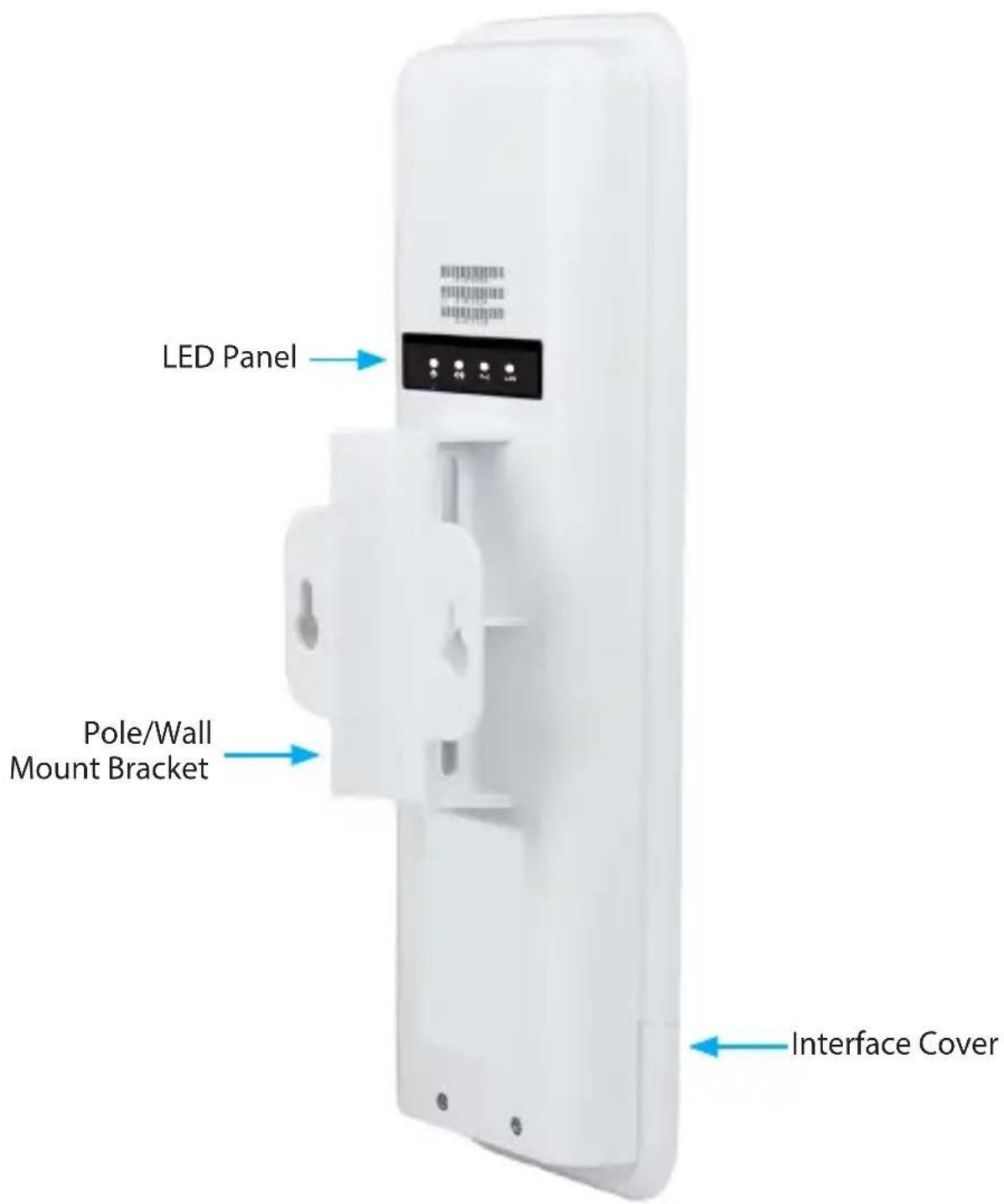
Product Diagram
Rear View
Introduction
Packaging Contents
• 1 x Outdoor Access Point
- 1 x PoE Injector
- 1 x Metal Hose Clamp
- 1 x Power Adapter
• 1 x Quick Start Guide (CD)
System Requirements
- A networked computer system with a Java-enabled web browser (for configuration)
- Cat 5 (or better) network cabling from PoE Injector to Wireless AP and PoE Injector to LAN Switch/router (no more than 100m total)
- Mounting screws / anchors if wall mounting PoE Injector and/or Wireless AP
Connection Ports
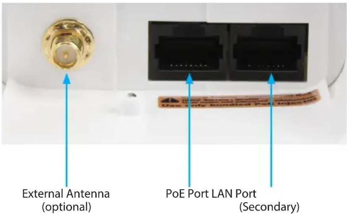
Interface Description
| External Antenna | External RP-SMA Antenna connector (optional).Upgradable to high gain antennas for more range. See the External Antenna configuration section for setup procedures. |
| PoE Port | Power over Ethernet RJ-45 port used to connect the Access Point to the included PoE Injector for power and data connectivity. |
| LAN Port (secondary) | RJ-45 port used to connect additional network devices to the Access Point. |
LED Indicators
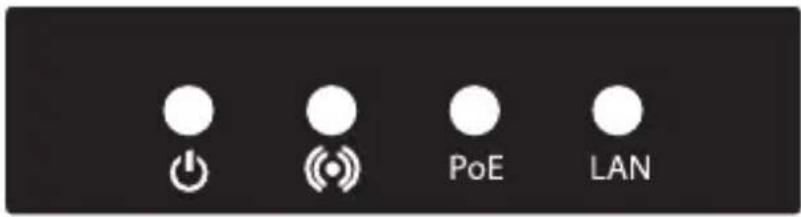
| Indicator State Description | ||
| PWR | ON The device is powered on | |
| Off The device is powered off | ||
| Wifi activity | Flashing Data is being transmitted / received over wireless | |
| Off No link detected | ||
| PoE | ON Link detected | |
| Off No link detected | ||
| Flashing | Data is being transmitted / received on the PoE LAN interface | |
| LAN | ON Link detected | |
| Off No link detected | ||
| Flashing | Data is being transmitted / received on the Secondary LAN interface | |
Installation
Preparing Your Site
- Determine the location for the included PoE injector and mount using the appropriate screws/anchors for the material you are mounting to (not included).
- Determine the location for the Wireless AP. If you are pole-mounting the AP, use the included clamp to secure the device. If you are wall mounting the AP, use the appropriate screws/anchors for the material you are mounting to (not included).
- Prepare/purchase the required length of Ethernet cabling to go from the PoE Injector to your LAN Switch or router, and from PoE Injector to the AP.
Note: The total length of Ethernet cabling from the Wireless AP to your LAN switch or router should not exceed 100m.
Hardware Installation
- Connect the included power adapter to an available wall outlet and the DC jack on the PoE injector.
- Connect an Ethernet cable from the LAN port of the PoE Injector to your LAN switch or router.
- Connect a second Ethernet cable from the PoE port of the PoE Injector, the other end of this cable will connect to the AP as instructed in the following steps.
- Slide the bottom cover of the unit down to remove it and expose the ports.
- Connect the Ethernet cable from the PoE port of the PoE Injector, to the PoE Port port on the AP (closest to the antenna connector).
- Slide the cover back on as shown.
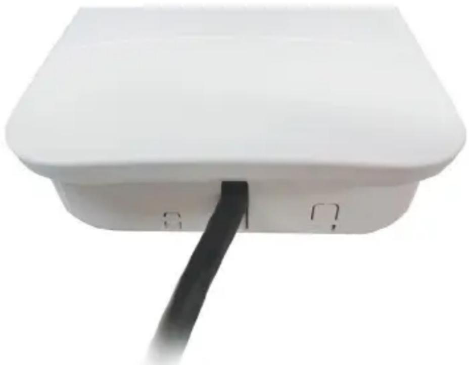
natural_image
White rectangular device with a black cable inserted into the base (no visible text or symbols)Note: the AP may take approximately up to 2 mins to complete the power on sequence.
Operation
Before operation, it is recommended that you ensure the Access Point is using the latest firmware version. Check www.startech.com/downloads for the latest firmware version.
Default Settings
SSID: AP150WN1X1OD
Security: None
Default IP Address: 192.168.1.200
ID: admin; PW: admin
DHCP: Auto
- Scan for available wireless networks on your PC and connect to the AP150WN1X1OD network
- Open a web browser and enter the IP address 192.168.1.200 into the address bar, then press Enter.
- When the web menu appears, click the Start button at the bottom of your screen to begin the Setup Wizard. The wizard will guide you through the following basic setup options:
a. System Clock
b. Network Name (wireless SSID)
c. Network Security
System Clock
The System Clock is used for system logs and setting schedules for Internet access. Click the Sync button to synchronize the System Clock with the time on your computer, or set manually.
Click Next to continue

System Clock
Update the System Clock for the Smart Access Point by clicking the Sync button below.
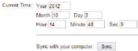
Click Next to confirm your settings and continue

Network Name
The default SSID of your Wireless Network is: AP150WN1X1OD
To change it, enter your desired name in the SSID field. Users connecting wirelessly to the Access Point will use this ID to identify your wireless network.
Click Next to continue

Network Name
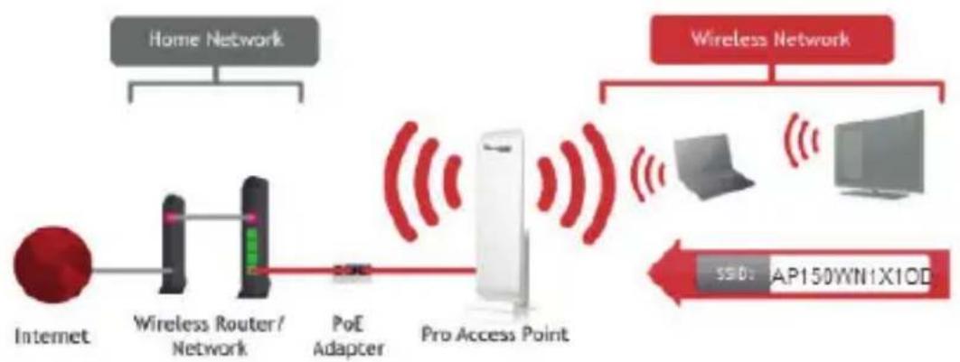
flowchart
graph LR
    A["Home Network"] --> B["Internet"]
    B --> C["Wireless Router/ Network"]
    C --> D["PoE Adapter"]
    D --> E["Pro Access Point"]
    E --> F["Wireless Network"]
    F --> G["AP150WN1X1OD"]
    G --> H["SSD: 6.0"]
Wireless Network ID (SSID): AP150WN1X10D
Click Next to confirm your settings and continue.

Network Security
By default, there is no Security Key configured on the Access Point. Enter your desired security key (WPA) in the Security Key field (recommended).
Note: The key must be at least 8 characters long
Click Next to apply your settings. The Access Point will reboot and may take up to 2 minutes. Please do not refresh the web page; it will automatically reload with the Setup Summary page with the details of what has been configured.

Network Security
Your wireless network is secured with the following (WPA) security password/key. You must enter this key when connecting wirelessly for the first time to the High Power Wireless-N 600mW Pro Access Point. You may change the key below.
Note: To specify the use of another type of encryption please view the More Settings > Wireless Settings > Security menu for more security options after your setup is complete.
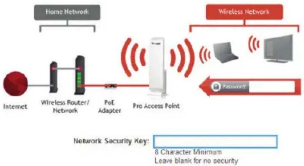
flowchart
graph LR
    A["Home Network"] --> B["Internet"]
    B --> C["Wireless Router/ Network"]
    C --> D["PoE Adapter"]
    D --> E["Pro Access Point"]
    E --> F["Wireless Network"]
    F --> G["Phone Icon"]
    F --> H["Computer Icon"]
    F --> I["Password*"]
    J["Network Security Key: 8 Character Minimum\nLeave blank for no security"]
Advanced Configuration
The following sections outline the advanced configuration settings available on the Access Point. These options can be accessed by clicking the More Settings link from the left side of the page, or by clicking the Finish button at the bottom of the Setup Summary page.
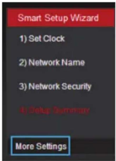
Wireless Settings
Basic
The Wireless Basic Settings page allows you to adjust the settings for your wireless network. These settings are for adjusting the Access Point after you have already gone through the Smart Setup Wizard and wish to further adjust your configurations.
Basic Settings
Disable Wireless LAN Interface: □
Band: 2.4 GHz (B+G+N)
Broadcast SSID: ● Enable ○ Disable
Data Rate: Auto
Wireless Network ID (SSID): AP150WN1X1OD
Multiple AP
Channel Width: 40MHz
Control Sideband: Upper
Channel Number: Auto
WMM: Enabled
Associated Clients: Show Active Clients
Disable Wireless LAN Interface:
Turns off all wireless access.
Band:
Allows you to setup access under a specific combination of Wi-Fi speed standards.
Broadcast SSID:
Disabling the broadcasting of your SSID will make it so outside users cannot see your network when they scan for wireless networks - users must manually enter the SSID to connect.
Data Rate:
Adjust the speed of your wireless network. It is recommended that you use Auto for this selection.
SSID of Wireless network:
This is the name of your Wireless network and the name that users will scan for to connect wirelessly.
Multiple AP:
You may add one additional (SSID) to you Wireless network. The additional SSID can have its own security, band and data rate settings. You may restrict users for specific SSIDs or provide access only to some users with lower bandwidth by changing the band (i.e. only allow 802.11b access to specific users).
Channel Width:
Wi-Fi operates in two separate channel widths, 20Hz and 40Hz. 20Hz allows operation on channels 1-11, while 40Hz is 5-11. 40Hz allows for faster speeds. Select the channel width you wish to use for your network.
Control Sideband:
This relates to the channel number used for your wireless network. An upper band represents higher channels and vice versa.
Channel Number:
The channel number used for your wireless network. If there are other wireless networks using the same channel, this may cause slower performance. You may adjust the channel here to attempt to improve performance through less interference.
WMM:
Prioritizes audio and video content going over your wireless network.
Associated Clients:
Displays all wireless connections to the Pro Access Point.
Security
Wireless security allows you to change the security type, password/key and format for your wireless network. The security key you select must be used by all computers and devices connecting to the Access Point wirelessly.
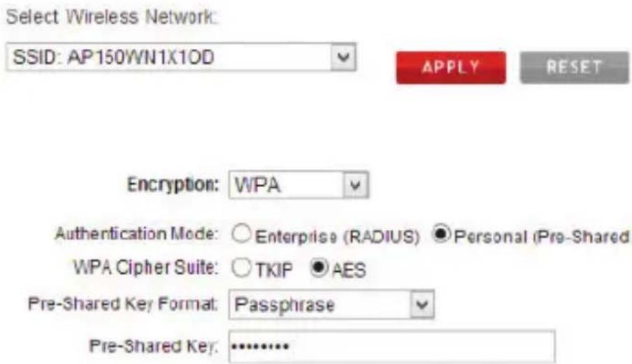
Using the drop down menu, you can select which network you wish to configure and adjust the security settings for (standard wireless network or the multiple SSID network).
Note: It is recommended to use WPA or WPA2 as your encryption type. WEP 64bit and 128bit security is a more primitive WiFi security encryption type which may limit wireless performance and speed from the Access Point. (Pre Service Pack 3 Windows XP computers may not support WPA2).
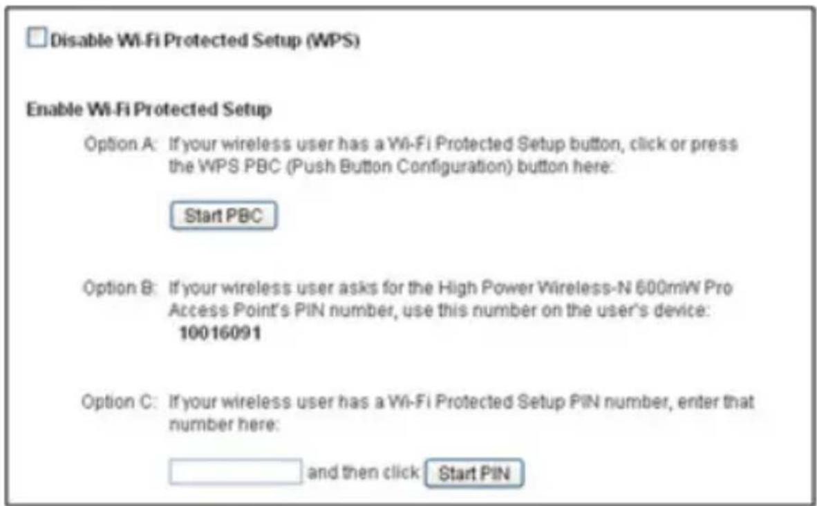
Wi-Fi Protected Setup (WPS)
WPS is a Wi-Fi feature created to make Wi-Fi setup simpler and easier. Some wireless devices and adapters support this feature with varying names (i.e. one touch setup or WPS). You may enable WPS setup here by selecting the type of WPS setup you wish to use. Push button
You may push the WPS button on the web menu. The Access Point does not have a physical WPS button.
WDS Settings
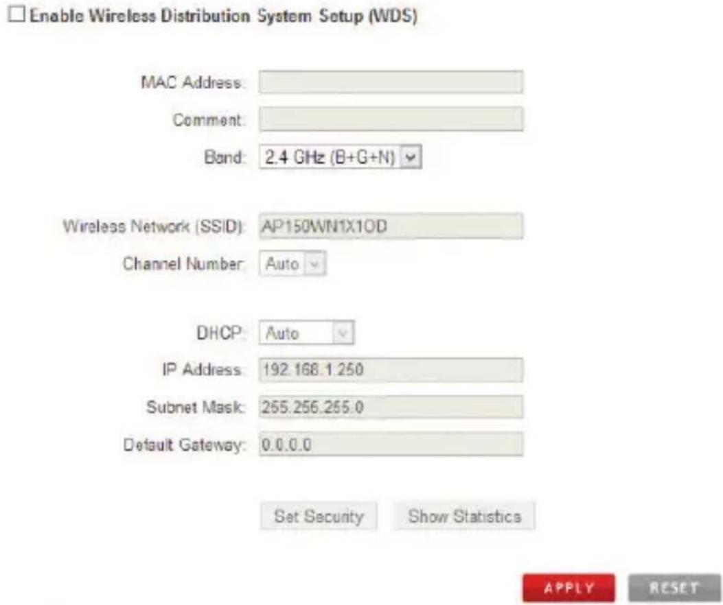
Wireless Distribution System (WDS) allows you to use the Access Point to wirelessly connect to other Access Points. In WDS mode, the Access Point can function as a Main Access Point which is connected to a network using a cable, or it can be a Relay Access Point which is wirelessly connected to the Main Access Point.
Current WDS AP List

To configure WDS mode you will need to adjust the settings for the following fields:
a) Enable WDS: First you must enable the WDS function to use it.
b) MAC Address: Enter the MAC address of the Access Point that you wish to connect to. If you are configuring the Main Access Point then you would need to enter the Relay Access Point's MAC Address here.
c) Comment: Provide a comment, such as "Main Access Point" to easily remember which Access Point belongs to which MAC Address entry.
d) Band: Select the wireless band you wish to operate on.
e) Wireless Network (SSID): Enter the wireless SSID of your Access Point. Do not use the same SSID for two separate Access Points.
f) Channel: Ensure that all Access Points, Main or Relay, operate on the same wireless channel.
g) DHCP: WDS mode requires that you have a static IP address for your Access Point. Enter a static IP address for your Access Point by selecting "Disable" under the DHCP field.
h) IP Address: The IP address of the Access Point should be on the same subnet as the Main or Relay Access Points. For example, if the network you are connected to has an IP address range of 192.168.1.100 – 192.168.1.200, then the IP address of the Access Point should be 192.168.1.1xx.
i) Subnet Mask: The subnet mask for the Access Point should be the same as the network you are connecting to. (e.g. 255.255.255.0)
j) Default Gateway: This entry is typically the IP address of your network router. (e.g. 192.168.1.1)
Antenna Settings
The Access Point includes an internal High Gain Antenna, however if you wish to use an external antenna instead, you may activate the External Antenna port here. The External Antenna Port is a RP-SMA port and accepts RP-SMA antenna connections. It is compatible with most high gain antennas.
Note: It is important that you attach the external antenna to the External Antenna Port BEFORE activating the External Antenna Port to avoid damage to the Access Point.
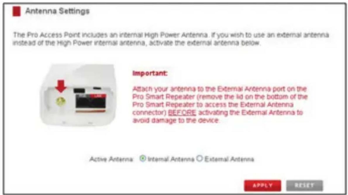
After you have attached the external high gain antenna, select the External Antenna selection under Active Antenna and click Apply. After the Access Point reboots, your external antenna will be active and ready for use.
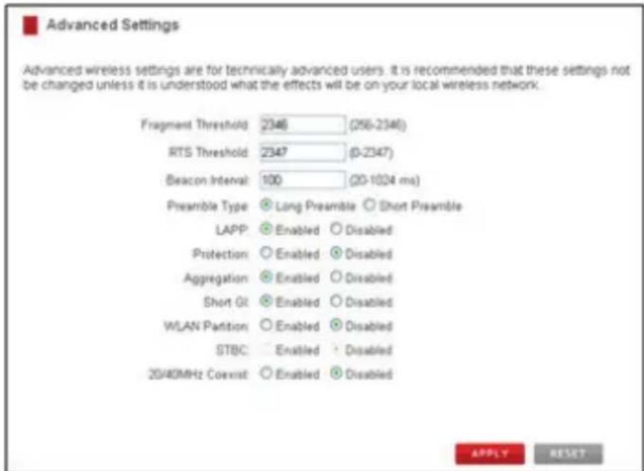
Advanced Settings
These settings allow you to control the advanced details of your wireless network configuration. Please use caution in changing these settings.
Smart Features
The Access Point provides Smart Features that offer convenience and protection for your wireless network. The Smart Features allow you to control access to your wireless network through on/off schedules, specific user authorizations, as well as through the range of your wireless coverage for your.
Note: These settings only apply to users connecting through the Access Point to your network.
Access Schedule
Set a schedule for when your Wi-Fi is enabled or disabled through the Access Schedule feature.
Note: Ensure your Time Zone Settings have been configured in order for your schedule to work correctly. Time Zone Settings can be adjusted from the web menu under Management > Time Zone Settings.
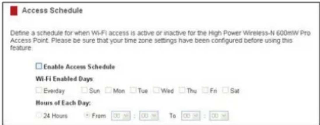
To do so:
a) Click Enable Access Schedule
b) Select which days you wish for your Wi-Fi to be available
c) Select the time frame during that day that you wish for Wi-Fi to be available
d) Apply Changes
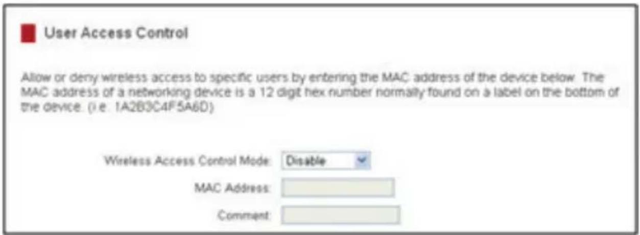
User Access Control
User Access lets you deny / allow access to specific users connecting wirelessly to your network by MAC address. By inputting the MAC address(es) into this area, you can define whether that device is allowed into your network or not allowed. When entering the MAC addresses, only enter alpha-numerical characters (e.g. A1B233C45566).
Wireless Coverage Controls
Adjust the output power of the Access Point to control the coverage distance of your wireless network. For a smaller coverage area you can select a lower output power percentage. For the maximum wireless coverage, select 100%.
Note: If you select a lower output power, your connection to your Home Network will also decrease in range. So be sure to test your signal strength after each adjustment.

Wireless Coverage Controls
Adjust the output power and range of your Long Range Wireless-N Pro Access Point. For a smaller coverage area, choose a lower output power percentage. For a larger coverage area, select a higher output power percentage.
Wireless Output Power: ○100% ○70% ○50% ○35% ●15%
IP Settings
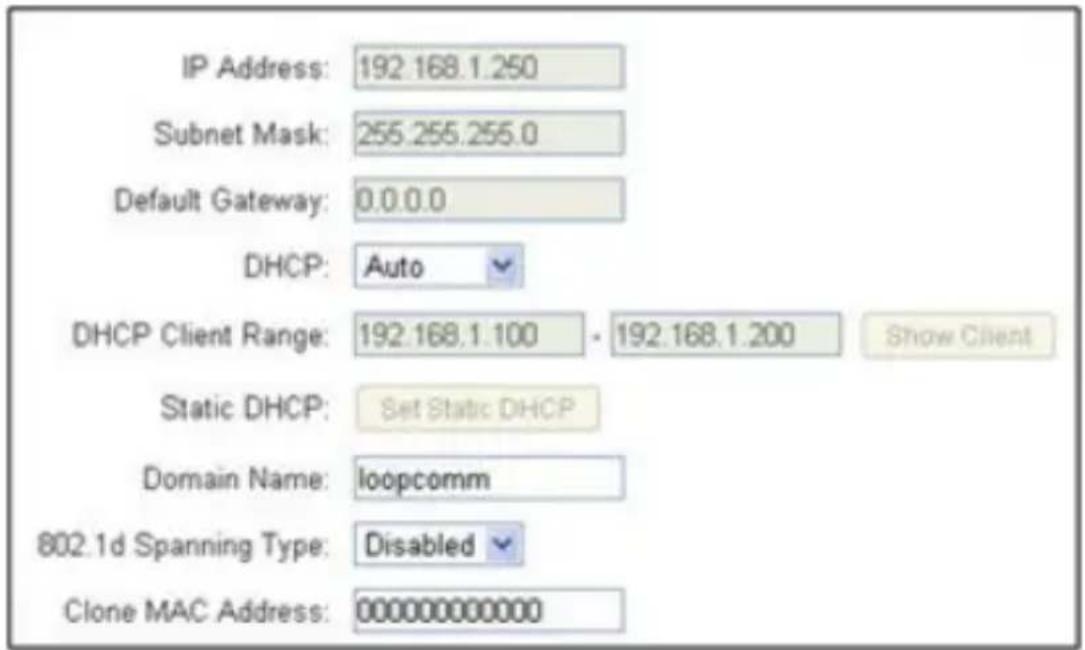
IP Address:
The IP address of the Access Point.
Subnet Mask:
The subnet of the Access Point.
Default Gateway:
The Access Point to another network, normally the IP address of your router.
DHCP:
The Access Point includes a 'Smart' AUTO DHCP feature to help manage the IP addresses within your wireless network and with your router. When the Access Point is connected to your home network/router through the 'Network' port, the AUTO DHCP will determine whether it can receive an IP address from your router. If it can, it will automatically switch to a client and allow your router to assign it an IP address.
When there is no connection available, the Access Point will act as a DHCP Server. You may also manually control the IP settings of the Access Point by choosing Client, Server or Disabled from the DHCP drop down menu.
DHCP Client Range:
The range of IP addresses the Access Point's DHCP server will assign to devices connecting to the Access Point.
Disabled / Static DHCP:
If your network requires the use of manual IP address assignments, select this option. You may manually enter the IP address settings of the Access Point so it reflects the correct addresses to work with your specific network.
Management Settings
The Management features on the Access Point allow you to view the status of your Access Point and your wireless network.
System Status
The Access Point System Status page provides full information regarding the system, wireless network and configurations as well as the current IP settings of the Access Point. This page is often used to check the health of your wireless network and the link to your home router/network.
Network Statistics
The Network Statistics page provides detailed traffic data for each connection type. View this page to see the amount of traffic going through the Access Point's wired or wireless connections.
System Clock
Maintain the internal clock for the Pro Access Point by syncing with your computer's time. Your system clock settings need to be accurate in order for system logs and wireless access schedules to work correctly.
Upgrade Firmware
In the event that a new firmware file is available you may update it here. During the upgrade process DO NOT power off the device to avoid damage to the Access Point. Check www.startech.com/downloads for the latest firmware version.
Upgrade Firmware
The Long Range Wireless-N Pro Access Point uses software (firmware) to operate. In the event that a new firmware file is available you may update it here. During the upgrade process DO NOT power off the device to avoid damage to the device.
Current Firmware Version: 1.21.03
Build Time: Tue Oct 1 08 04 09 CST 2013

To manually upgrade your firmware:
a. Download the file from the www.startech.com/downloads and remember the location where you saved it.
b. Click Browse and locate the file.
c. Click Upload to begin.
Save and Reload Settings
Allows you to back-up your current settings which may be reloaded at a later time. This feature may be useful for testing new features and settings without having to worry about returning to a stable platform.
You may also reset the Access Point's settings to factory settings by pressing Reset. By resetting the Access Point you will lose all previous configurations and will need to run the Smart Setup Wizard again to reconnect to a Home Network.
In addition to the web interface, the PoE Injector has a small reset button located on the rear side. Press and hold the reset button for 10 seconds to restore all settings to factory default.

Save/Reload Settings
Save your current Long Range Wireless-N Pro Access Point configurations to a file or reload previously saved configurations. If needed, you may also reset your Pro Access Point to factory default settings.

Password Settings (recommended)
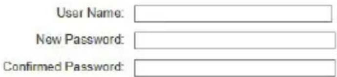
By default, the Access Point does not require a password to log in to the web menu. If you wish to enable a password to protect unauthorized access to the web menu and Smart Setup Wizard, you may enter one here.

Password
Prevent unauthorized access to your Long Range Wireless-N Pro Access Point's configuration menu by providing a user name and password. If no protection is necessary, leave these fields blank and you will not be prompted for a login and password when accessing this web menu.

Specifications
| Supported Wireless Standards IEEE802.11 b/g/n | |
| Chipset Realtek - 8196C | |
| Connectors | 2 x RJ45 Ethernet Female1 x RP-SMA (Coax; Reverse Polarity SubMiniature A) Female |
| Antenna Configuration 1x1:1 (TxR:s) | |
| Antenna Type 12dBi Directional Antenna | |
| Wireless Frequency Range 2.400 ~ 2.484GHz | |
| Wireless Bandwidth 20/40MHz | |
| Wireless Encryption Supported | 64/128 bit WEPWPA(TKIP with IEEE 802.1x)WPA2(AES with IEEE 802.1x)WPA Mixed |
| Maximum Data Transfer Rate | 802.11n : (40MHz) : up to 150Mbps802.11n : (20MHz) : up to 72MbpsRJ45 Ethernet: 10/100 Mbps |
| Enclosure Material Plastic | |
| Operating Temperature 0°C to 70°C (32°F to 122°F) | |
| Storage Temperature -20°C to 70°C (-4°F to 158°F) | |
| Humidity 10~90% RH | |
| Dimensions 282 x 80 x 55 mm | |
Technical Support
StarTech.com's lifetime technical support is an integral part of our commitment to provide industry-leading solutions. If you ever need help with your product, visit www.startech.com/support and access our comprehensive selection of online tools, documentation, and downloads.
For the latest drivers/software, please visit www.startech.com/downloads
Warranty Information
This product is backed by a two year warranty.
In addition, StarTech.com warrants its products against defects in materials and workmanship for the periods noted, following the initial date of purchase. During this period, the products may be returned for repair, or replacement with equivalent products at our discretion. The warranty covers parts and labor costs only. StarTech.com does not warrant its products from defects or damages arising from misuse, abuse, alteration, or normal wear and tear.
Limitation of Liability
In no event shall the liability of StarTech.com Ltd. and StarTech.com USA LLP (or their officers, directors, employees or agents) for any damages (whether direct or indirect, special, punitive, incidental, consequential, or otherwise), loss of profits, loss of business, or any pecuniary loss, arising out of or related to the use of the product exceed the actual price paid for the product. Some states do not allow the exclusion or limitation of incidental or consequential damages. If such laws apply, the limitations or exclusions contained in this statement may not apply to you.
Hard-to-find made easy. At StarTech.com, that isn't a slogan. It's a promise.
StarTech.com is your one-stop source for every connectivity part you need. From the latest technology to legacy products — and all the parts that bridge the old and new — we can help you find the parts that connect your solutions.
We make it easy to locate the parts, and we quickly deliver them wherever they need to go. Just talk to one of our tech advisors or visit our website. You'll be connected to the products you need in no time.
Visit www.startech.com for complete information on all StarTech.com products and to access exclusive resources and time-saving tools.
StarTech.com is an ISO 9001 Registered manufacturer of connectivity and technology parts. StarTech.com was founded in 1985 and has operations in the United States, Canada, the United Kingdom and Taiwan servicing a worldwide market.
- Outdoor 150Mbps Wireless N Access Point - 1T1R 2.4GHz
- FCC Compliance Statement
- Use of Trademarks, Registered Trademarks, and other Protected Names and Symbols
- Important Notice
- Table of Contents
- Product Diagram....1
- Introduction......2
- Connection Ports....3
- Installation 4
- Hardware Installation....5
- Operation 6
- Specifications....19
- Technical Support 20
- Warranty Information......20
- Product Diagram
- Rear View
- Introduction
- Packaging Contents
- System Requirements
- Connection Ports
- LED Indicators
- Installation
- Preparing Your Site
- Hardware Installation
- Operation
- Default Settings
- System Clock
- Network Name
- Network Security
- Advanced Configuration
- Wireless Settings
- Basic
- Basic Settings
- Disable Wireless LAN Interface:
- Band:
- Broadcast SSID:
- Data Rate:
- SSID of Wireless network:
- Multiple AP:
- Channel Width:
- Control Sideband:
- Channel Number:
- WMM:
- Associated Clients:
- Security
- Wi-Fi Protected Setup (WPS)
- WDS Settings
- Antenna Settings
- Advanced Settings
- Smart Features
- Access Schedule
- To do so:
- User Access Control
- Wireless Coverage Controls
- IP Settings
- IP Address:
- Subnet Mask:
- Default Gateway:
- DHCP:
- DHCP Client Range:
- Disabled / Static DHCP:
- Management Settings
- System Status
- Network Statistics
- Upgrade Firmware
- Save and Reload Settings
- Save/Reload Settings
- Password Settings (recommended)
- Password
- Technical Support
- Warranty Information
- Limitation of Liability
Brand : StarTech.com
Model : AP150WN1X1OG
Category : Access Point