SP400 - Receiver Citronic - Free user manual and instructions
Find the device manual for free SP400 Citronic in PDF.


| Product Type | Audio Receiver |
| Brand | Citronic |
| Model | SP400 |
| Power Output | 2 x 100W RMS at 4 ohms |
| Frequency Response | 20 Hz - 20 kHz ±1 dB |
| Total Harmonic Distortion | < 0.1% |
| Signal-to-Noise Ratio | > 90 dB |
| Inputs | 3x RCA, 1x AUX 3.5mm, 1x Optical, 1x Coaxial |
| Outputs | 2x Speaker Binding Posts, 1x Subwoofer Pre-out |
| Tuner | FM/AM with 30 presets |
| Bluetooth | Yes, version 5.0 |
| Power Supply | AC 220-240V, 50/60 Hz |
| Power Consumption | 300W max, < 0.5W standby |
| Dimensions (W x H x D) | 430 x 140 x 320 mm |
| Weight | 8.5 kg |
| Cooling | Passive heat sink ventilation |
| Remote Control | Included (IR) |
| Protection Features | Short circuit, overload, overheating |
| Cabinet Material | Aluminum front panel, steel chassis |
| Warranty | 2 years limited |
Frequently Asked Questions - SP400 Citronic
User questions about SP400 Citronic
0 question about this device. Answer the ones you know or ask your own.
Ask a new question about this device
Download the instructions for your Receiver in PDF format for free! Find your manual SP400 - Citronic and take your electronic device back in hand. On this page are published all the documents necessary for the use of your device. SP400 by Citronic.
USER MANUAL SP400 Citronic
Professional Power Amplifier Owner's Manual

SP Series
Professional Power Amplifier
Before attempting to connect, operate or adjust this product, please read these instructions completely.
Rev: 2.0-CITRONIC-SP 11/2010
SP Series
PROFESSIONAL POWER AMPLIFIER

Congratulations on your choice of stereo power amplifiers — you have purchased one of the finest stereo amplifiers on the market today. This unit was developed using the expertise of professional sound engineers and working musicians. You will find that your new SP Series has superior performance and greater flexibility than any other amplifiers in its price range. Please read this manual carefully to get the most out of your new unit.
Thanks for selecting SP Series as your choice in stereo power amplifiers.
FEATURES
Offering top power, superior performance and full professional operating features in a roadworthy compact chassis, the SP Series Bold Type are perfect for even the most demanding sound reinforcement installation and touring applications.
The operating instruction in this manual are for the SP Series power amplifiers. The operation and functions of these units are the same, except as noted.
. Full operating features: detent volume controls ; replace with text 1/4" TRS jack balanced inputs speak on out
. Roadworthy, rugged double rack space (1U) housing. \~115V AC 60Hz, \~230V AC 50Hz select switch and IEC
. Full safety/reliability features: 2 variable speed fans for cooling; noise-free on-off; DC and thermal overload protection; short circuit and speaker protection; Power ON, Clip, Signal, and Protect LED indicators for each channel
TABLE OF CONTENTS
FEATURES 3
WARNING 4
FRONT & REAR PANEL CONNECTIONS .... 5
INSTALLATION 6
SPECIFICATIONS 7
Date of Purchase
Dealer \$Name ____
City ____
State ____ Zip ____
Model # ____
Serial # ____
WARNING
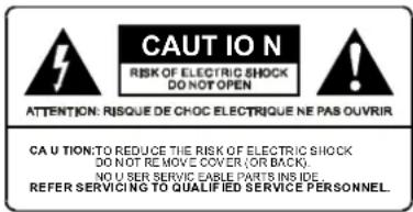

An equilateral triangle enclosing a lightening flash/arrowhead symbol is intended to alert the user to the presence of uninsulated "dangerous voltage" within the product's enclosure which may be of sufficient magnitude to constitute a risk of electric shock.

An equilateral triangle enclosing an exclamation point is intended to alert the user to the presence of important operating and service instructions in the literature enclosed with this unit.
IMPORTANT SAFETY INSTRUCTIONS
When using this electronic device, basic precautions should always be taken, including the following:
- Read all instructions before using the product.
- Do not use this product near water (e.g., near a bathtub, washbowl, kitchen sink, in a wet basement, or near a swimming pool, etc.).
- This product should be used only with a cart or stand that will keep it level and stable and prevent wobbling.
-
This product, in combination with headphones or speakers, may be capable of producing sound levels that could cause permanent hearing loss. Do not operate for a long period of time at a high volume level or at a level that is uncomfortable. If you experience any hearing loss or ringing in the ears, you should consult an audiologist.
-
The product should be positioned so that proper ventilation is maintained.
-
The product should be located away from heat sources such as radiators, heat vents, or other devices (including am plifiers) that produce heat.
-
The product should be connected to a power supply only of the type described in the operating instructions or as marked on the product. Replace the fuse only with one of the specified type, size, and correct rating.
-
The power supply cord should: (1) be undamaged, (2) never share an outlet or extension cord with other devices so that the outlet's or extension cord's power rating is exceeded, and (3) never be left plugged into the outlet when not being used for a long period of time.
-
Care should be taken so that objects do not fall into, and liquids are not spilled through, the enclosure's openings.
-
The product should be serviced by qualified service personnel if:
A. The power supply cord or the plug has been damaged.
B. Objects have fallen into, or liquid has been spilled onto the product.
C. The product has been exposed to rain.
D. The product does not appear to operate normally or exhibits a marked change in performance.
E. The product has been dropped, or the enclosure damaged.
- Do not attempt to service the product beyond what is described in the user maintenance instructions. All other servicing should be referred to qualified service personnel.
FRONT & REAR CONNECTIONS
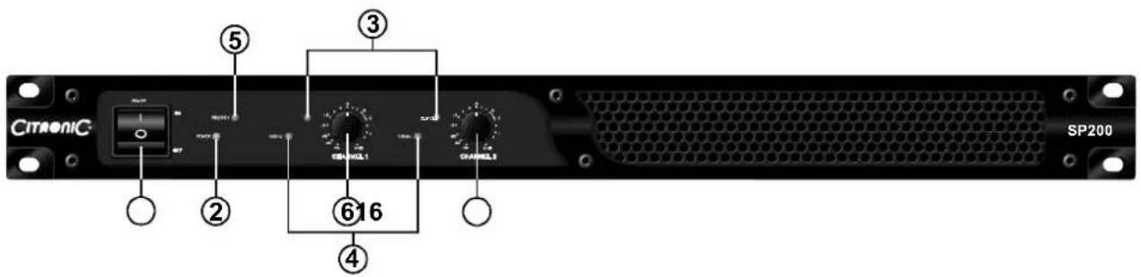
FRONTPANEL
1. POWERSWITCH
To turn the unit ON or OFF, press the Left or Right portion of this button. Before turning on the amplifier, check all connections and turn down the level controls. A momentary muting is normal when turning the amplifier on or off.
(Caution: Always turn on your power amplifier last, after all your other connected equipment, and always turn off your power amplifier before your other connected equipment.)
2. POWERLEDINDICATORS
These LEDs illuminate when the power is turned "ON".
3. LIMITLEDINDICATORS
These LEDs illuminate if any section of the power amplifier's output are within 3dB of clipping. Occasional blinking of the LEDs are acceptable, but if they remain on more than intermittently you should turn down either the power amplifier's level controls or
reduce the output level of the preceding component to avoid audible distortion.
4.SIGNALLEDINDICATORS
These LEDs illuminate to confirm the presence of an input signal greater than 100 mV at that channel of the amplifier
5.PROTECTLEDINDICATORS
These LEDs illuminate if the power amplifier s output connection is shorted or the load impedance is too low. When either of these LEDs is lit up, turn OFF the power and check the output's connection to verify that it is correct, then turn ON the power again.
6.LEVELCONTROLS
These control the level of signal coming into each channel. The actual voltage gain of the amplifier is shown in dB. Turn these controls counterclockwise if the peak LEDs illuminate steadily (indicating too strong an input signal).
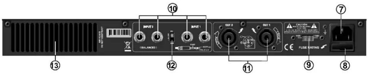
BACKPANEL
7. POWERCONNECTOR
The cord connector is used to connect the AC power source to your power amplifier.
(CAUTION:DONOTREMOVETHECENTERGROUNDING PIN.)
8.FUSES
Fuse holders. If these fuses continuously blow, shut off the unit and have it serviced by qualified service personnel.
9.ACVOLTAGESELECTORSWITCH
Before plugging in the power cord, check to see that the unit is set for the proper voltage for your a rea:\~115V(60Hz)or \~230V(50Hz).
10. INPUT CONNECTORS
Connect your input signal to these balanced 1/4"TRS input jacks.
11.L/RCHANNELOUTPUTCONNECTORS
Connect to your speaker box.
12.BUILTIULIMITERON/OFFSELECTOR
13.FANS
The fan speed is varied continuously and automatically to maintain the proper internal operating temperature.
INSTALLATION
To ensure years of enjoyment from your SP Series, please read and understand this manual thoroughly before using the unit.
INSPECTION
Your SP Series was carefully packed at the factory in packaging designed to protect the units in shipment. Before installing and using your unit, carefully examine the packaging and all contents for any signs of physical damage that may have occurred in transit.
(Note: SP Seriesonsible for shipping damage.
Remove If the unit is damaged, do not return to us, but notify your dealer and the shipping company immediately to make a claim. Such claims must be made by the consignee in a timely manner.)
CONTENTS
. Instruction manual
. SP Series (verify that the unit's serial number is same as shown on shipping carton)
. AC Power cord
RACK MOUNTING
The SIR series are designed for standard 19" rack mounting as well as "stack" mounting without a cabinet. Use 4 screws and washers for mounting to the front rack rails. It is also a good idea to support the amps also in the rear, especially for mobile use where the amps will be subjected to shocks.
AMPLIFIER COOLING
Also pay close attention to the cooling requirements. Never block the air vents in the back, side and front of the amplifier if the load seen by amplifier is less than 4 ohms and the amplifier is being run at high output levels. For best results, in such high output power applications you should augment the amplifier's air flow with a rack cooling system.
SPECIFICATIONS
| POWER SPECIFICATIONS | SP200 | SP400 |
| STEREO INTO (4 Ω) | 100W | 200W |
| STEREO INTO (8 )Ω | 70W | 130W |
| POWER SPECIFICATIONS | SP200 | SP400 |
| INPUT SENSITIVITY | 0.77V | |
| INPUT IMPENDANCE | 10k balanced | |
| FREQUENCY RESPONSE(at 10db below rated output power) | 25Hz~25KHz +0/-1dB -3dB points:5Hz~50KHz | |
| DISTORTION (SMPTE-1M) | <0.03% | |
| S/N RATIO | 100dB | |
| GENERAL SPECIFICATIONS | SP200 | SP400 |
| PROTECTIONS | Full short circuit, open circuit, thermal, Ultrasonic, and RF Protection; stable into reactive or mismatched loads; ON/OFF muting; current limiter | |
| CONTROLS | Front: Power switch, 41 detent input level control for each channel. | |
| INDICATORS | SIGNAL: 2 x green LEDLIMIT: 2 x red LEDPOWER: 1 x blue LEDPROTECT: 1x red LED | |
| CONNECTORS | POWER: IEC power cord | |
| INPUT: 1/4" (6.3mm)TRSOUTPUT: SPEAKON | ||
| POWER SUPPLY | Voltage selectable: 115V AC 60Hz 230V AC 50Hz | |
| FUSES (250V) | AC115V:T4A/250VAC230V:T2A/250V | AC115V:T6.3A/250VAC230V:T3.15A/250V |
| DIMENSIONS | 19.0" x 12.6" x1.73" (482 x 320 x 45mm) | |
| WEIGHT (kg) | 8.0Kg | 8.3Kg |
The specifications above are correct at the time of printing of this manual. For improvement purposes, all specifications for this unit, including design and appearance, are subject to change without prior notice.
- Professional Power Amplifier Owner's Manual
- SP Series
- PROFESSIONAL POWER AMPLIFIER
- FEATURES
- TABLE OF CONTENTS
- WARNING
- IMPORTANT SAFETY INSTRUCTIONS
- FRONT & REAR CONNECTIONS
- FRONTPANEL
- POWERSWITCH
- POWERLEDINDICATORS
- LIMITLEDINDICATORS
- 4.SIGNALLEDINDICATORS
- 5.PROTECTLEDINDICATORS
- 6.LEVELCONTROLS
- BACKPANEL
- POWERCONNECTOR
- 8.FUSES
- 9.ACVOLTAGESELECTORSWITCH
- INPUT CONNECTORS
- 11.L/RCHANNELOUTPUTCONNECTORS
- 12.BUILTIULIMITERON/OFFSELECTOR
- 13.FANS
- INSTALLATION
- INSPECTION
- CONTENTS
- RACK MOUNTING
- AMPLIFIER COOLING
- SPECIFICATIONS
Brand : Citronic
Model : SP400
Category : Receiver