PPX300 - Receiver Citronic - Free user manual and instructions
Find the device manual for free PPX300 Citronic in PDF.


| Product Type | Power Amplifier |
| Brand | Citronic |
| Model | PPX300 |
| Power Supply | 240Vac, 50Hz (IEC inlet) |
| Power Output (RMS @ 8 Ohms) | 100W + 100W |
| Power Output (RMS @ 4 Ohms) | 150W + 150W |
| Bridge Mode Power (RMS @ 8 Ohms) | 300W |
| Input Impedance | 20k ohms |
| Frequency Response | 5Hz - 50kHz |
| Total Harmonic Distortion | 0.05% |
| Slew Rate | 40V/µs |
| Damping Factor | >400 |
| Protection Features | Short-circuit, overload, DC, thermal protect |
| Controls | CH1/CH2 level, Ground Lift, Mode (Stereo/Bridge), Limiter switch |
| Input Connectors | XLR and 6.3mm jack (parallel per channel) |
| Output Connectors | Binding posts and SPK connectors |
| Dimensions (WxHxD) | 483 x 88 x 266mm (2U rackmount) |
| Weight | 8.2kg |
| Cooling | Front ventilation grille and rear fan |
| Cleaning | Soft cloth with neutral detergent; vacuum vents |
| Safety | Avoid moisture, do not open case, use qualified service |
Frequently Asked Questions - PPX300 Citronic
User questions about PPX300 Citronic
0 question about this device. Answer the ones you know or ask your own.
Ask a new question about this device
Download the instructions for your Receiver in PDF format for free! Find your manual PPX300 - Citronic and take your electronic device back in hand. On this page are published all the documents necessary for the use of your device. PPX300 by Citronic.
USER MANUAL PPX300 Citronic
Caution: Please read this manual carefully before operating Damage caused by misuse is not covered by the warranty
Introduction
Thank you for choosing a Citronic PPX series power amplifier as part of your sound reinforcement system. This high output amplifier is designed to offer high quality, dependable service for mobile and installed systems. Please read this manual fully and follow the instructions to achieve the best results with your new purchase and to avoid damage through misuse.
Warning
To prevent the risk of fire or electric shock, do not expose any of the components to rain or moisture. If liquids are spilled on the casing, stop using immediately, allow unit to dry out and have checked by qualified personnel before further use. Avoid impact, extreme pressure or heavy vibration to the case No user serviceable parts inside – Do not open the case – refer all servicing to qualified service personnel.
Safety
- Check for correct mains voltage and condition of IEC lead before connecting to power outlet
• Ensure speaker leads are good condition with no short connections or damaged plugs - Check impedance of speaker loads do not exceed the minimum stated load for the amplifier
• Do not allow any foreign objects to enter the case or through the ventilation grilles
Placement
- Keep out of direct sunlight and away from heat sources
- Keep away from damp or dusty environments
- When rack-mounting, ensure adequate support for the base of the amplifier and firm fixings for the front
• Ensure adequate air-flow and do not cover cooling vents at the front and rear of the amplifier - Ensure adequate access to controls and connections
Cleaning
• Use a soft cloth with a neutral detergent to clean the casing as required
• Use a vacuum cleaner to clear ventilation grilles of any dust or debris build-ups
• Do not use strong solvents for cleaning the unit
Front Panel
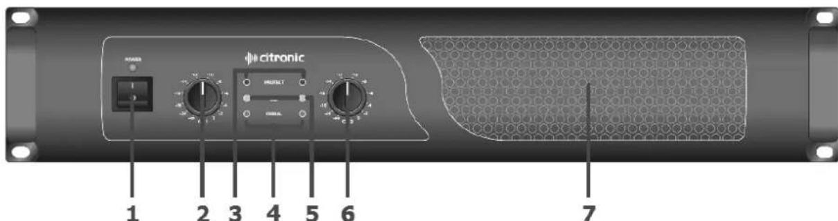
- Power switch and LED
- CH1 level control
- Protect LED indicators
- Signal LED indicators
- Clip LED indicators
- CH2 level control
- Cooling vent
Rear Panel
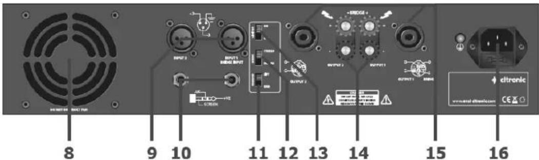
- Cooling fan vent
- CH1 & CH2 XLR inputs
- CH1 & CH2 jack inputs
- GROUND LIFT switch
- MODE switch
- LIMITER switch
- CH1 & CH2 binding post speaker outputs
- CH1 & CH2 SPK connector outputs
- IEC mains inlet and fuse
Operation
Connect speaker cabinets to channel outputs using good quality leads via the SPK connector or binding posts and ensure that the combined load on each channel is no lower than 4 . (for speaker loads connected in parallel, 8 + 8 = 4 )
Both channels can be used to drive a single load at the combined volume of each by switching to BRIDGE mode. In this mode, the input is on channel 1 and output from CH1 SPK connector (pins 1+ and 2-) or across the red "+" terminals as indicated on the rear panel - WARNING - Minimum load for bridge mode is 8Ω
Connect each signal input from mixer or other line level source via the XLR or jack connectors on the rear panel using good quality signal leads.
For protection in high power situations, the onboard LIMITER may be switched in to protect from overload. In situations with excessive mains hum coming through the speakers, it may help to switch the GROUND to the LIFT position. This is may help in some situations but otherwise, it is preferred to be switched to GND.
Jack and XLR inputs for each channel are wired in parallel, allowing the signal to be carried forward to further amplifiers if necessary (if the input is XLR, the jack may be used as a signal output and vice versa)
Connect the amplifier to a mains outlet, ensuring that the IEC lead is earthed, in good condition and connected securely. With channel gain controls turned fully down, switch on the power to the amplifier. This unit has a "soft-start" function which makes some checks before engaging power to the amplifiers, which may take a few seconds.
With mixer (or other signal source) levels turned down, gradually increase the amplifier's channel level controls to the required level (normally full) and then gradually increase the signal level from the mixer or sound source until sound can be heard through the speakers and then continue increasing up to the required level.
During use, green "SIGNAL" LEDs will illuminate to show when a signal is present and yellow "CLIP" LEDs illuminate if the output is reaching clip level. If the red CLIP LEDs illuminate more than very briefly, reduce the volume until they hardly light up at all.
If the internal protection circuitry detects a fault in the speakers or amp, the channel(s) will enter Protect Mode and red "PROTECT" LEDs will illuminate on the front panel to show this. Switch the amplifier off and check the entire system (including leads) before powering up again. If still in Protect Mode, seek advice from qualified service personnel.
Before powering down, turn the channel gain controls fully down to avoid loud noises when switching off.
Specifications
| Model | PPX300 | PPX600 | PPX900 |
| Power supply | 240Vac, 50Hz (IEC) | ||
| Controls | Level channel 1, level channel 2, ground, mode, clip limiter | ||
| Input impedance | 20k ohms | ||
| Frequency response | 5Hz - 50kHz | ||
| Total harmonic distortion | 0.05% | ||
| Slew rate | 40V/us | ||
| Damping factor | >400 | ||
| Protection | Short-circuit, overload, D.C. and thermal protect | ||
| Power RMS @ 4 Ohms | 150W + 150W | 300W + 300W | 450W + 450W |
| Power RMS @ 8 Ohms | 100W + 100W | 200W + 200W | 300W + 300W |
| Power RMS bridge @ 8 ohms | 300W | 600W | 900W |
| Dimensions | 88 x 483 x 266mm (2U) | 88 x 483 x 266mm (2U) | 88 x 483 x 428mm (2U) |
| Weight | 8.2kg | 8.8kg | 13.8kg |
Troubleshooting
| No power light on front panel switch | Ensure IEC inlet is connected to mains and lead is in good condition |
| Ensure mains outlet is switched on | |
| Power light is on but no other LEDs and no output | Check input signal and connection leads |
| Ensure channel gain controls are not turned fully down | |
| Power light and Signal LEDs are lit but no output | Check speaker cabinets are in good working order |
| Check speaker leads are in good condition and connected properly | |
| PROTECT LED is lit and there is no output | Switch off and disconnect from mains |
| Check speakers are in good working order and not shorted out (using a multi-tester) | |
| After checking all connected items, power up again | |
| If still in Protect Mode, switch off again and refer to qualified service personnel | |
| Ensure cooling vents are clear and amplifier is not overheated | |
| Output is very distorted and “CLIP” LEDs are lighting | Check the speaker impedance is not below 4 Ohms per channel (8 Ohms if bridged) |
| Turn down the input level from audio source | |
| Turn down channel gain controls | |
| Output is working but at very low level | Ensure input source is at line level |
| Increase input level from audio source | |
| Turn up channel gain controls |
Brand : Citronic
Model : PPX300
Category : Receiver