
ADTV3.1 - Receiver AudioSource - Free user manual and instructions
Find the device manual for free ADTV3.1 AudioSource in PDF.


| Product Type | Digital TV Receiver |
| Brand | AudioSource |
| Model | ADTV3.1 |
| Dimensions (W x D x H) | 20 cm x 15 cm x 5 cm |
| Weight | 0.5 kg |
| Power Supply | DC 12V, 1A |
| Power Consumption | 5W (max) |
| Video Output | HDMI 1.4, Composite AV |
| Audio Output | HDMI, Optical, Analog Stereo |
| USB Port | 1 x USB 2.0 for media playback |
| Supported TV Standards | DVB-T/T2, DVB-C |
| Channel Search | Automatic and manual scan |
| Remote Control | Includes IR remote with batteries |
| Display | LED indicator for power and signal |
| Media Playback | MPEG-4, H.264, AVI, MKV, MP3, JPEG |
| Recording | USB recording (PVR ready) |
| EPG | Electronic Program Guide support |
| Subtitles | DVB subtitles support |
| Teletext | Supported |
| Parental Control | Channel locking with PIN |
| Operating Temperature | 0°C - 45°C |
| Storage Temperature | -10°C - 60°C |
| Cleaning Instructions | Wipe with a soft, dry cloth. Do not use liquid cleaners. |
| Safety Precautions | Do not expose to rain or moisture. Ensure proper ventilation. |
| Spare Parts / Repairability | No user-serviceable parts inside. Contact authorized service center for repairs. |
Frequently Asked Questions - ADTV3.1 AudioSource
User questions about ADTV3.1 AudioSource
0 question about this device. Answer the ones you know or ask your own.
Ask a new question about this device
Download the instructions for your Receiver in PDF format for free! Find your manual ADTV3.1 - AudioSource and take your electronic device back in hand. On this page are published all the documents necessary for the use of your device. ADTV3.1 by AudioSource.
USER MANUAL ADTV3.1 AudioSource
ADTV3.1, ADTV2.1
3/2 CHANNEL AMPLIFIER WITH ARC
FCC Statement
This equipment has been tested and found to comply with the limits for a Class B digital device, pursuant to part 15 of the FCC Rules. These limits are designed to provide reasonable protection against harmful interference in a residential installation. This equipment generates, uses and can radiate radio frequency energy and, if not installed and used in accordance with the instructions, may cause harmful interference to radio communications. However, there is no guarantee that interference will not occur in a particular installation. If this equipment does cause harmful interference to radio or television reception, which can be determined by turning the equipment off and on, the user is encouraged to try to correct the interference by one or more of the following measures:
- Reorient or relocate the receiving antenna.
- Increase the separation between the equipment and receiver.
- Connect the equipment into an outlet on a circuit different from that to which the receiver is connected.
- Consult the dealer or an experienced radio/TV technician for help.
Caution: Any changes or modifications to this device not explicitly approved by manufacturer could void your authority to operate this equipment.
This device complies with part 15 of the FCC Rules. Operation is subject to the following two conditions: (1) This device may not cause harmful interference, and (2) this device must accept any interference received, including interference that may cause undesired operation.
RF Exposure Information
This equipment complies with FCC radiation exposure limits set forth for an uncontrolled environment. This equipment should be installed and operated with minimum distance 20cm between the radiator and your body.

CAUTION
RISK OF ELECTRIC SHOCK DO NOT OPEN
ATTENTION
RISQUE DE CHOC ELECTRIQUE NE PAS OUVRIR

WARNING:
To reduce the risk of fire or electric shock, do not expose this apparatus to rain or moisture.
AVIS:
The apparatus shall not be exposed to dripping or splashing and that no objects filled with liquids, such as vases, shall be placed on apparatus.
The lightning flash with arrowhead symbol, within an equilatera triangle, is intended to alert the user to the presence of uninsulated "dangerous voltage" within the product's enclosure that may be of sufficient magnitude to constitute a risk of electric shock to persons.
This symbol is intended to alert the user to the presence of important operation and maintenance (servicing) instructions in the literature accompanying the appliance.
Important Safety Instructions
-
Read these Instructions. Lisez ces instructions.
-
Keep these Instructions. Conservez ces instructions.
-
Heed all Warnings. Respectez tous les avertissements.
-
Follow all instructions. Suivez toutes les instructions.
-
Do not use this apparatus near water. Ne pas utiliser cet appareil près de l'eau.
-
Clean only with a dry cloth. Nettoyer uniquement avec un chiffon sec.
-
Do not block any ventilation openings. Install in accordance with the manufacturer's instructions. Ne pas bloquer les ouvertures de ventilation. Installer conformément aux instructions du fabricant.
-
Do not install near any heat sources such as radiators, heat registers, stoves, or other apparatus (including amplifiers) that produce heat.
- Do not defeat the safety purpose of the polarized or grounding - type plug, polarized plug has two blades with one
wider than the other. When the provided plug does not fit into your outlet, consult an electrician for replacement of the obsolete outlet.
- Protect the power cord from being walked on or pinched particularly at plugs, convenience receptacles, and the point where they exit from the apparatus.
-
Only use attachments/accessories specified by the manufacture. N'utilisez que des accessoires spécifiés par le fabricant.
-
Use only with a cart, stand, tripod, bracket, or table specified by the manufacturer, or sold with the apparatus. When a cart or rack is used, use caution when moving the cart/apparatus, combination to avoid injury from tip-over.
- Unplug this apparatus during lightning storms or when unused for long periods of time.
- Refer all servicing to qualified service personnel. Servicing is required when the apparatus has been damaged in any way, such as power-supply cord or plug is damaged, liquid has been spilled or objects have fallen into the apparatus, the apparatus has been exposed to rain or moisture, does not operate normally, or has been dropped.
- WARNING: The appliance coupler is used as disconnect device, the disconnect device shall remain readily operable.
- No naked flame sources, such as lighted candles, should be placed on the apparatus.
- Protective earthing terminal. The apparatus should be connected to a mains socket outlet with a protective earthing connection.
Thank you for purchasing Audiosource Amplifier products. Audiosource is a high performance custom installed product engineered for home and commercial sound installations. Each Audiosource product is manufactured to the highest quality standard using state-of-the-art components and built for years of enjoyment.
Contents in the Box
• ADTV3.1 OR ADTV2.1
• Power Supply
• IR Receiver with mounting adhesive
• (2) Mounting brackets
• Handheld Remote Control with battery
- User Manual
Features
• 3 Channel (LCR) Amplifier(ADTV3.1)
2 Channel (LR) Amplifier(ADTV2.1)
- 75 Watts L&R, 80 Watts Center(ADTV3.1)
75 Watts L&R(ADTV2.1)
- Small Size, Lightweight
• Short Circuit & Thermal Protection
• HDMI Input with ARC (Audio Return Channel)
• Analog RCA Inputs
- Optical Input
• Wireless Audio Connectivity
• Variable Sub Output
- Auto On
- Trigger On
- Front Panel LED's Indicate Mode & Remote Learning Confirmation
• Handheld Remote Included
• TV Remote IR Learning Capability
- Extendable IR Receiver Included
- Brackets for Vertical Wall/Cabinet Mounting Included
- Outboard Power Supply Included (AC110 - 230V Input to 28VDC Output)
Rear Panel
- Power Switch
- DC Power Input jack (28VDC)
- BT Antenna
- Dip Switches (D1 - D5)
Rear Panel

D1 & D2: Dip switches are used in combination to set the default input mode as shown below:
Input 1/BT (Wireless Audio Connectivity): D1-UP & D2-UP NOTE: The wireless Audio Connectivity pairing name is: ADTV3.1, ADTV2.1。
IN4/AUX: D1-DOWN & D2-DOWN If the amplifier is powered off, once the power is restored, it will go to the mode set by the dip switches above, otherwise it will stay in the last mode you selected.
NOTES ON INPUT MODE OPERATING LOGIC
The D1 & D2 switch settings for the default input mode are only the priority when you are not operating with the handheld remote control. Once you use the remote to select a different input mode, the unit will always remember the last mode selected until you power the amplifier off/on by removing the power from the DC input jack (2) or unplugging it from the AC outlet. When the amplifier is powered off/on it will start up with the input set by the D1 & D2 dip switches.
When using the auto-on mode (D4-UP, and the unit is in standby mode), the amplifier will only turn back on if signal is applied to the last input selected before it went into standby. You can also use the remote to power the unit on manually.
D3: Volume Fixed/Adjustable mode: D3-UP for variable mode (remote control volume will function) D3-DOWN for fixed volume mode (remote control volume will not function)
D4: Auto-On Mode: D4-UP for auto-on mode (amplifier will turn on when signal is applied to inputs, unit will go into standby approximately 30 minutes after signal is removed) D4-DOWN for manual power ON/OFF control via the handheld remote
D5: IR RUN/LEARN: D5-UP for RUN (normal operation) D5-DOWN for IR LEARNING. TV learning functions: On/Off, Mute, Volume -, Volume + (more about IR learning later)
-
IR IN: 3.5mm TRS connector for attaching the supplied IR receiver. All handheld remote commands and IR learning must pass through the IR receiver. For proper operation, the IR receiver must be located for the remote to be within line of sight for it to function.
-
TRIGGER IN (5-12VDC, tip +): Applying voltage to the Trigger In will turn the amplifier on. When the voltage is removed the amplifier will go into standby after 30 minutes
-
ARC IN: For ARC or eARC operation (more about this later)
-
AUX IN: Analog stereo L/R RCA inputs
-
OPT IN: Toslink Digital Optical Fiber Input
-
SUB OUT: RCA line level output for a power subwoofer or sub amp
-
SPEAKER OUTPUTS:
ADTV3.1: Phoenix-style connector with 6 set screws for connecting Left, Center & Right speakers
ADTV2.1: Phoenix-style connector with 4 set screws for connecting Left, & Right speakers
Front Panel
Front panel LED indications:
A. Wireless Audio Connectivity mode: Left LED-Blue
B. ARC mode: Right LED-Yellow
C. Optical Fiber mode: Left LED-Purple
D. AUX mode: Right LED-Green
E. Standby Mode: Left LED-Red
F. Remote learning LED operation:
- Enter and learn confirmation: Green
- Learn error: Red
• All learning completed: Blue
Installation
First, plan your amplifier location, be sure you choose a location that will allow the outboard power supply, all connecting cables and the IR receiver to reach the amplifier. When choosing the location, you need to consider the front of the amplifier has 2 LED's that are helpful for operation. These LEDs provide visible verification of the source selected & IR learning confirmation.
Before you permanently mount the amplifier, temporarily connect:
- All the sources to the inputs
- Speakers
- Subwoofer (if applicable)
- IR receiver
Power the unit on and check the operation. If everything works as desired, unplug the power supply and move forward to permanently mount the amplifier in its final location. If you plan to sit the ADTV3.1,ADTV2.1 on a tabletop or on a shelf, the unit comes with rubber feet on the bottom that will keep it from sliding or scratching the surface of the table/shelf. If you want to mount the unit vertically on a wall behind a TV, inside a cabinet or in a structured wiring enclosure you will need to attach the (2) supplied mounting brackets. First remove (4) Phillips-head screws, (2) from each side of the amplifier. Note: Each bracket has 2 counter-sunk holes and 2 oval-shaped holes. Use the (4) screws you removed from the amplifier to attach the brackets to the amplifier sides going through the counter-sunk holes in each bracket. Make sure your method of mounting the ADTV3.1,ADTV2.1 to a vertical wall surface is secure and into studs if possible. You may want to
attach the unit to the TV mount, just be sure to use a good secure method of mounting the amplifier to the TV mount and make certain it doesn't interfere with the mount's tilt or swivel operation. The supplied IR receiver has a 1.5 meter cable that allows it to be located away from the amplifier in case your amplifier location is out of sight. The IR receiver needs to be mounted using the supplied adhesive pad so it has a clear line of sight to the user's location so the ADTV3.1,ADTV2.1 handheld remote control (or TV remote) can transmit IR signals to the amplifier.
Typical Setups
Important TV Audio Setting When using the Optical input or the HDMI ARC Input, your TV audio must be set to PCM Output.
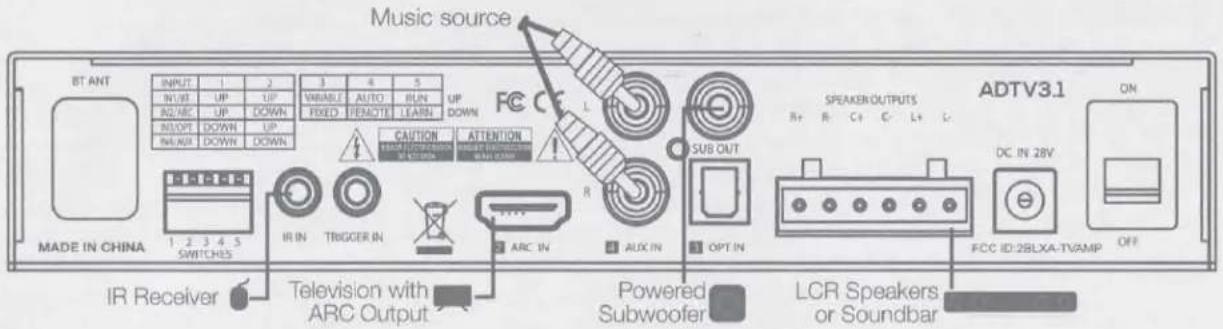
Typical 3-channel TV setup using the ARC input with Left-Center-Right or Soundbar speakers & subwoofer connected + AUX music source via RCA
You need to set your TV audio output to PCM for the amplifier to operate. Set dip switch D1-Up, D2-Down for HDMI In. If you set dip switch D4-Down the amplifier will automatically turn on when the TV is turned on via the HDMI ARC function. NOTE: In HDMI ARC mode you will not need the ADTV3.1,ADTV2.1 handheld remote for on/off or volume operation, these commands will come from your TV's remote control. Install the IR remote receiver so that you can switch from ARC input to AUX input via IR remote control.

Typical 2-channel analog audio setup with Left & Right speakers
This configuration is for typical 2-channel Left/Right analog audio using Aux IN RCA inputs. The IR receiver needs to be connected for remote control of power, volume, input selection and Bass/Treble EQ. It also shows an (optional) trigger connection that will turn the amplifier on/off when 5-12VDC is applied or removed. Set dip switch D1 & D2 down for Aux In as the default startup.


Typical 3-channel TV setup using the optical input with Left-Center-Right or a passive soundbar speaker & subwoofer output This configuration requires an optical audio cable from your TV's optical output. You need to set your TV audio output to PCM for the amplifier to operate. The IR receiver must be connected to allow the amplifier's remote to control power, volume, inputs and Bass/Treble EQ. Set dip switch D1-down, D2-Up for Optical In as the default startup. If you set dip switch D4-Up for auto-on, the amplifier will automatically turn on when the TV is turned on.
What do you need to use HDMI ARC?
To take advantage of HDMI ARC, you'll need a television with ARC or eARC-enabled HDMI connectors. Examine the back of your TV – if it has three or four HDMI connections, you need to find the one that's labelled 'ARC' or 'eARC'. Labelling isn't compulsory for the TV industry, but if your TV is a late-2009 model or newer, there should be one you can use to connect to the ADTV3.1,ADTV2.1 HDMI input. Consult the TV's user manual if you are unsure.
With many TVs, HDMI ARC will work automatically, but if it doesn't, you might need to check the TV settings, including turning off your TV's built-in speakers and enabling your TV to send audio out to an external speaker or amp. If your TV has eARC and you are not successful getting audio via the ADTV3.1,ADTV2.1, you might need to use a high-speed HDMI 2.1 cable.
Speaker Wire Termination
Follow the steps below to connect your speakers to the 6-position Phoenix connector:

- Strip the outer jacket of a multi-conductor speaker wire back about 2", and then strip the insulation of each wire back approximately 1/4"
- Remove the Phoenix connector from the amplifier and loosen the set screws using a 1/8" flat-blade screwdriver
- Twist the strands of each individual wire clockwise and insert each one into the appropriate hole as shown in the diagram below. Be sure to observe the wire colors for polarity which will insure proper speaker operation. WARNING: Do not allow any strands of copper wire to touch between the terminals to avoid a short circuit which could prevent proper operation or damage the amplifier.
- Tighten the set screws to secure the wires and firmly replace the connector into the amplifier.
Handheld Remote

- Power (Toggles amplifier On/Off)
- IN 1: Wireless Audio Connectivity (Note: Wireless Pairing name will be ADTV3.1 OR ADTV2.1)
3.Mute
4.IN 2: ARC Input
5.IN 3: Optical Input
6.IN 4: Aux Input - Volume: Down (-), Up (+)
- Bass EQ Controls: Down (-), Up (+), Flat
9.Treble EQ Controls: Down (-), Up (+), Flat - Battery compartment in rear. NOTE: User must pull safety tab to engage the battery before use
Remote Control Battery
The Remote Control uses a CR2025 button-cell battery that can be easily removed and changed from the rear, bottom of the remote by sliding the small cover off.

Warning:
Do not ingest battery, Chemical Burn Hazard.
The remote control is supplied with a coin cell battery. If the battery is swallowed, it can cause severe internal burns in under 2 hours and can lead to death. Keep new and used batteries away from children. If the battery compartment does not close securely, stop using the product and keep it away from children. If you think batteries might have been swallowed or placed inside any part of the body, seek medical attention immediately.
Caution, dangerous conditions can occur, or batteries may be damaged if exposed to:
- Extreme temperatures during use, storage, and/or transportation.
- Low air pressure at high altitudes.
- Replacement batteries are not the correct size/type.
- Disposal of a battery into fire or a hot oven, or mechanically crushing or cutting of a battery, that can result in an explosion.
- Extremely high temperatures can result in an explosion or leakage of flammable liquid or gas.
- Extremely low air pressure may result in an explosion or leakage of flammable liquid or gas.
IR Connection, Control and Learning
Mount the supplied IR receiver on a shelf edge or edge of a TV using the adhesive pad so it has a clear line of sight to the user's position. The IR receiver has a wide angle of acceptance as shown in the illustration below, but it should be positioned so it is centrally aimed at the primary listening/viewing position in the room.

Connect the IR receiver's 3.5mm plug to the IR IN jack on the amplifier. You are now ready to use the ADTV3.1,ADTV2.1 remote or your TV's remote once its commands are learned (see IR Learning).
IR Learning
IR learning allows control of the amplifier using the TV's remote or any other remote you might have. The ADTV3.1,ADTV2.1 can learn these four commands: Power On/Off, Mute, Volume (-) and Volume (+). Note, these four commands must be learned in order for the ADTV3.1,ADTV2.1 to work with the TV remote (more below).
Learning Steps:
A. Set dip switch D5 to the down (LEARN) position. The ADTV3.1, ADTV2.1 front panel Green LED should flash quickly to indicate it is ready to learn your TV's remote-control key commands.
B.First click the On/Off button of your TV's remote control while aiming it at the ADTV3.1,ADTV2.1's IR Receiver. If the code is read successfully, the green light on the front of the ADTV3.1,ADTV2.1 will be on for 2 seconds, and the next key (Mute, see below) will be ready to be learned. If the learning fails, the red light will be on for 2 seconds, and the next key can be learned, or you can cycle dip switch D5 up to RUN and back to LEARN to start over. NOTE: All four learn buttons must be done for successful learning operation.
C. Proceed in the same fashion as above for the Mute button, Volume (-) then Volume (+) in that order.
D. After learning the four keys of Power, Mute, Volume (-) and Volume (+) the blue light will be on for 2 seconds indicating success in learning all 4 commands. Immediately move dip switch D5 to the UP (RUN) position and the TV remote will now be able to control the four functions of the ADTV3.1,ADTV2.1.
E. NOTE: If you do not set dip switch D5 back to the up position (RUN) within 30 seconds of the last learning function there is no learning process.
F. If the ADTV3.1,ADTV2.1 has failure to learn any of the four TV remote functions you will need to re-learn from the beginning. Set dip switch D5 up to (RUN) then back down to the LEARN position to start the learning sequence from the start.
Troubleshooting
| No audio | Power supply cable to the amplifier is not fully plugged in or the power supply is plugged into an AC outlet that does not have power. Check connections and verify power at the outlet.Audio cable to the source component is not connected properly, is connected to the incorrect input, or the cable is defective.Set the input volume level higher.Make certain you have audio output from the sourceCheck the speaker connections and wiring for proper setup. |
| Hum or buzzing sound is heard | Check RCA input cables by removing them one at time (powering down the amplifier before disconnecting) and checking to see if a connection or cable is to blame. |
| Amplifier will not turn on | The amplifier's power supply must be plugged into an AC outlet that has power.The power switch on the rear of the amplifier must be onThe handheld remote must have a clear line of sight to the IR receiverThe handheld remote might have a dead battery. |
| Amplifier will not auto-on | Make sure the amplifier power supply is plugged into an AC outlet that has power and that the rear panel power switch is ONCheck dipswitch D4 to be sure it is set to the AUTO (Up) position On.Make sure the correct source is selected.Check the source output to be sure it is sending an audio signal |
| Amplifier will not trigger-on | Make sure the amplifier power supply is plugged into an AC outlet that has power and that the rear panel and power switch is ONCheck the trigger voltage going to the ADTV3.1,ADTV2.1 is between 5 and 12 volts DC.Make sure the 3.5mm jack is 2-conductor, positive voltage on the tip of the connector and plugged into the jack all the way |
| Amplifier will not work with HDMI ARC or eARC input | Make certain you have a TV with HDMI ARC or eARC outputPower cycle (ON/OFF) the TV and ADTV3.1,ADTV2.1Check TV settings (CEC Enabled) for external audio out and internal speakers are turned "off"You might need to use an HDMI 2.1 cable for eARC |
| Amplifier Specifications | ||
| Model | ADTV3.1 | ADTV2.1 |
| Power Rating per Channel | 75 Watts L&R, 80 Watts Center @ 4 ohms | 75 Watts L&R, @ 4 ohms |
| Frequency Response | 20 Hz-20 kHz | |
| Total Harmonic Distortion-THD+N | ≤ 0.5% | |
| Input Sensitivity | 730 mv L&R, 560 mv Center (Aux IN) | 730 mv L&R, (Aux IN) |
| Input Impedance | 10kΩ | |
| Signal to Noise Ratio | ≥ 86 dB | |
| Sub Out Level | Variable, 2V max | |
| Sub Out Frequency Response | 20 Hz-100 Hz (-3dB @ 130 Hz, 12 dB/Octave roll-off) | |
| Protection | Short circuit and thermal protected | |
| Auto-On sensitivity for turn-on | 4 mv | |
| Auto off delay time | 30 minutes | |
| Wireless Audio Connectivity Receiving Range | >10 Meters | |
| Wireless Audio Connectivity Pairing Name | ADTV3.1 | ADTV2.1 |
| HDMI | Supports ARC and eARC | |
| Safety Certification | FCC,CE | |
| Power Requirement | 28VDC, 7.1 Amps | 28VDC, 5 Amps |
| Chassis Dimensions (W x D x H) | 7.992" (203 mm) x 5.197" (132 mm) x 1.417" (36 mm)9.173" (233 mm) wide with mounting brackets attached1.527" (38.8 mm) high with rubber feet | |
| Net Weight | 0.85 kg(Accessories such as adapters are not included) | 0.80 kg(Accessories such as adapters are not included) |
| IR Specifications | |
| Receiving Distance | Up to 10 Meters |
| Angle of IR Acceptance | +/- 45° from center line |
| Working voltage (VCC) | 2.7 – 5.5 VDC |
| Plug configuration | Tip: VCC, Ring: IR Signal, Sleeve: Ground |
| IR case dimensions | 0.657" (16.7 mm) x 1.16" (29.5 mm) |
| Cable length | 4.9' (1.5 Meters) |
| Remote Control Specifications | |
| Button Functions | On/Off, Mute, Wireless Audio Connectivity (BT), ARC IN, Optical IN, AUX In, Volume -/+ , Bass & Treble -/+ & Flat |
| Bass & Treble, Boost & Cut | +/- 6dB |
| IR Transmit Distance | Up to 10 Meters |
| Battery Required | CR2025 |
| Dimensions | 3.38" (86 mm) H x 1.61" (41 mm) W x 0.276" (7 mm) Thick |
| Power Supply Specifications | ||
| Input Voltage | 110 - 230V ~ 50/60Hz, 3.0A | |
| Output Voltage | 28VDC, 7.1A | 28VDC, 5A |
| Protection | Over Current & Short Circuit Protected | |
| Energy Saving | Level VI | |
| Safety Certifications | cULus, FCC, CE, UKCA | |
| AC Cable | Removable, 3-Prong Grounded, 4.9' (1.5 Meters) Long | |
| DC Cable | Hard wired, 2-conductor with 5.5 mm DC connector | |
ADTV3.1,ADTV2.1
![203mm [7.99"] 15mm [.59"] 15mm [.59"] 36mm [1.42"] AudioSource INSTALL POWER SUPPLIES ADTV3.1 ADTV8.1 ADTV8.1](/content/2026/05/959239/images/94d6a840a87d65efb0131fb516885424a30a23cdb00d5f551ab693dcf799c5f6.jpg)
![132mm [5.2"]](/content/2026/05/959239/images/c34fa7b5d5fb0c3f9df569e09c0058204a15dfe8e778ff452309dda33bf86b96.jpg)
![Handheld Remote 41mm [1.61"] 86mm [3.39"] 7mm [.28"]](/content/2026/05/959239/images/375a514da593e359a23ce4e69c16ba8fc50796d2bd1f247e8a9e47b669b05cb8.jpg)
Limited Warranty
AudioSource® warrants its amplifier products against defects in materials and workmanship for a limited period of time. For a period of two years from date of original purchase, we will repair or replace the product, at our option, without charge for parts and labor. Customer must pay all parts and labor charges after the limited warranty period expires. The limited warranty period for factory refurbished products expires after ninety (90) days from date of original purchase. This limited warranty applies only to purchases from authorized AudioSource® electronics retailers. This limited warranty is extended only to the original purchaser and is valid only to consumers in the United States. (Out to Additional Zones) Consumers are required to provide a copy of the original sales invoice from an authorized AudioSource® dealer when making a claim against this limited warranty. This limited warranty only covers failures due to defects in materials or workmanship that occur during normal use. It does not cover failures resulting from accident, misuse, abuse, neglect, mishandling, misapplication, alteration, faulty installation, modification, service by anyone other than AudioSource®, or damage that is attributable to Acts of God. It does not cover costs of transportation to AudioSource® or damage in transit. The customer should return his defective product, freight prepaid and insured, to AudioSource® only after receiving a Return Authorization. This warranty will become void if the serial number identification has been wholly or partially removed, altered or erased. Repair or replacement under the terms of this warranty does not extend the terms of this warranty. Should a product prove to be defective in workmanship or material, the consumer's sole remedies will be repair or replacement as provided under the terms of this warranty. Under no circumstances shall AudioSource® be liable for loss or damage, direct, consequential or incidental, arising out of the use of or inability to use the product. There are no express warranties other than described above.


- ADTV3.1, ADTV2.1
- 3/2 CHANNEL AMPLIFIER WITH ARC
- FCC Statement
- RF Exposure Information
- CAUTION
- ATTENTION
- WARNING:
- AVIS:
- Important Safety Instructions
- Contents in the Box
- Features
- Rear Panel
- NOTES ON INPUT MODE OPERATING LOGIC
- Front Panel
- Front panel LED indications:
- Installation
- Typical Setups
- Typical 3-channel TV setup using the ARC input with Left-Center-Right or Soundbar speakers & subwoofer connected + AUX music source via RCA
- Typical 2-channel analog audio setup with Left & Right speakers
- What do you need to use HDMI ARC?
- Speaker Wire Termination
- Remote Control Battery
- IR Connection, Control and Learning
- IR Learning
- Learning Steps:
- Limited Warranty
Brand : AudioSource
Model : ADTV3.1
Category : Receiver