
AD3002 - Receiver AudioSource - Free user manual and instructions
Find the device manual for free AD3002 AudioSource in PDF.


| Product Type | Stereo Receiver / Amplifier |
| Brand | AudioSource |
| Model | AD3002 |
| Power Output (Stereo 8Ω) | 150W per channel, <0.2% THD+N |
| Power Output (Stereo 4Ω) | 275W per channel, <0.2% THD+N |
| Power Output (Bridged Mono 8Ω) | 600W, 1kHz, <0.2% THD+N |
| Frequency Response | 20Hz - 20kHz |
| Signal-to-Noise Ratio | 100dBr referenced to 0.2% THD+N @ 8Ω |
| Channel Separation | 60dB @ 1kHz, referred to 150W into 8Ω |
| Input Sensitivity | Variable, 350mV to 2.8V for rated power into 8Ω |
| Bass Control | ±12dB @ 100Hz |
| Treble Control | ±12dB @ 10kHz |
| AC Power Consumption | 750W maximum |
| Net Weight | 8 lbs / 3.6 kg |
| Gross Weight | 11 lbs / 5.0 kg |
| Speaker Selection | A/B switching, A+B possible |
| Inputs | Main RCA, Interrupting RCA, Optical (PCM 2-channel), Speaker Level |
| Outputs | Speaker A and B binding posts, Main RCA pass-through |
| Front Panel Controls | Power switch, Speaker selector, Balance, Volume Trim (digital encoder) |
| Rear Panel Controls | Master volume L/R, Bass/Treble, Mode (Stereo/Bridged), Delay Time, Power Mode (Auto/Trigger/Normal) |
| Remote Control | Mute, Power/Standby, Volume +/-, Speaker A/B |
| Protection | Overload, short circuit, thermal; front panel red LED indicates protection |
| Rack Mountable | Yes (rack ears included) |
| Warranty | 2 years (3 years via Crutchfield) |
Frequently Asked Questions - AD3002 AudioSource
User questions about AD3002 AudioSource
0 question about this device. Answer the ones you know or ask your own.
Ask a new question about this device
Download the instructions for your Receiver in PDF format for free! Find your manual AD3002 - AudioSource and take your electronic device back in hand. On this page are published all the documents necessary for the use of your device. AD3002 by AudioSource.
USER MANUAL AD3002 AudioSource
Auxiliary line output
Speaker A/B switching
Front panel Level and Balance Trim controls
Independent rear mounted Main Level controls
High Level inputs
Digital Optical line input (PCM 2 Channel Decoding)
Multi-function IR remote control
Signal sensing "Power On" and Trigger mode
Rear mounted treble and bass controls
Rack mountable (rack ears included)
Congratulations on your purchase of the AudioSource® AD3002. Please take a few moments to read this entire manual, and be sure to retain this document for future reference. Please read and observe all safety instructions detailed on page 2.
NOTE: If any part of this product is damaged or missing, please call your dealer or AudioSource® directly at 1.877.715.5439 or 503.914.4688.
Please read your warranty and retain your receipt and original carton for possible future use.
For more information about AudioSource® electronics, speakers and accessories please visit www.audiosource.net
SPECIFICATIONS
Stereo (8 ohm): 150W per channel, <0.2% THD+N
Stereo (4 ohm): 275W per channel, <0.2% THD+N
Bridged Mono (8 ohm): 600W, 1kHz, <0.2% THD+N
Frequency Response: 20Hz \~ 20kHz
Signal to Noise Ratio: 100dBr referenced to .2% THD+N @ 8 ohms w/20kHz Lowpass filter
Channel Separation: 60dB @ 1kHz, referred to 150W output into 8 ohms
Input Sensitivity: Variable, 350mV to 2.8V for rated power into 8 ohms
Bass/Treble Control: +/- 12dB @ 100Hz and 10kHz
AC Power Consumption: 750W maximum
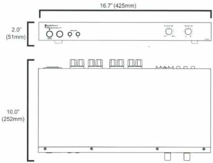
Net Weight: 8lbs / 3.6kgs
Gross Weight: 11lbs / 5.0kgs

CAUTION
RISK OF ELECTRICAL SHOCK DO NOT OPEN

CAUTION: TO REDUCE THE RISK OF ELECTRIC SHOCK, DO NOT REMOVE THE COVER. NO USER SERVICABLE PARTS INSIDE. REFER SERVICING TO QUALIFIED PERSONNEL!
EXPLANATION OF SAFETY SYMBOLS

The exclamation point within an equilateral triangle is intended to alert the user of the presence of important operating and maintenance (servicing) instructions in the literature accompanying the appliance.

The lightning flash with the arrowhead symbol within an equilateral triangle is intended to alert the user to the presence of uninsulated "dangerous voltage" within the products' enclosure that may be of sufficient magnitude to constitute a risk of electric shock to persons.
IMPORTANT SAFETY INSTRUCTIONS
- WARNING: TO PREVENT FIRE OR SHOCK HAZARD, DO NOT EXPOSE THIS APPLIANCE TO RAIN OR MOISTURE. THE APPARATUS SHALL NOT BE EXPOSED TO DRIPPING OR SPLASHING AND THAT OBJECTS FILLED WITH LIQUIDS, SUCH AS VASES, SHALL NOT BE PLACED ON APPARATUS.
- WARNING: TO PREVENT FIRE OF SHOCK HAZARD, DO NOT USE THIS PLUG WITH AN EXTENSION CORD, RECEPTACLE OR OTHER OUTLET UNLESS THE BLADES CAN BE FULLY INSERTED TO PREVENT BLADE EXPOSURE.
-
WARNING: THE MAINS PLUG IS USED AS DISCONNECT DEVICE. THE DISCONNECT DEVICE SHALL REMAIN READILY AVAILABLE.
• WARNING: ONLY USE ATTACHMENTS OR ACCESSORIES SPECIFIED OR PROVIDED BY THE MANUFACTURER. -
Read these instructions.
- Keep these instructions.
- Heed all warnings.
- Follow all instructions.
- Do not use this apparatus near water.
- Clean only with dry cloth.
- Do not block any ventilation openings. The ventilation should not be impeded by covering the ventilation openings with items such as newspaper, tablecloths, curtains etc. Install in accordance with the manufacturer's instructions.
- Do not install near heat sources such as radiators, heat registers, stoves, or other apparatus (including amplifiers) that produce heat. No open flame sources, such as lighted candles, should be placed on the apparatus.
- Do not defeat the safety purpose of the polarized or grounding type plug. A polarized plug has two blades with one wider than the other. A grounding type plug has two blades and a third grounding prong. The wide blade or third prong is provided for your safety. If the provided plug does not fit into your outlet, consult an electrician for replacement of the obsolete outlet.
- Protect the power cord from being walked on or pinched particularly at the plugs, convenience receptacles, and at the point of exit from the apparatus.
-
Only use attachments/accessories specified by the manufacturer.
-
Use only with the cart, stand, tripod, bracket, or table specified by the manufacturer, or sold with the apparatus. When a cart or rack is used, use caution when moving the cart/apparatus combination to avoid injury from tip-over.

- Unplug the apparatus during lightning storms or when unused for long periods of time.
- Refer all servicing to qualified personnel. Servicing is required when the apparatus has been damaged in any way, such as power supply cord or plug is damaged, liquid has been spilled or objects have fallen into the apparatus has been exposed to rain or moisture, does not operate normally, or has been dropped.
- WARNING: To reduce the risk of fire or electric shock, do not expose this apparatus to rain or moisture. The apparatus shall not be exposed to dripping or splashing and that objects filled with liquids, such as vases, shall not be placed on apparatus.
- WARNING: The mains plug/appliance coupler is used as disconnect device, the disconnect device shall remain readily operable.
- This equipment is a Class II or double insulated electrical appliance. It is designed in such a way that it does not require a safety connection to electrical earth.

ATTENTION: RISQUE DE CHOC ELECTRIQUE-NE PAS OUVRIR
18.
- This lightning flash with arrowhead symbol within an equilateral triangle is intended to alert the user to the presence of non-insulated "dangerous voltage" within the product's enclosure that may be of sufficient magnitude to constitute a risk of electric shock.
- Warning: to reduce the risk of electric shock, do not remove cover (or back) as there are no user-serviceable parts inside. Refer servicing to qualified personnel.
- The exclamation point within an equilateral triangle is intended to alert the user to the presence of important operating and maintenance instructions in the literature accompanying the appliance.
MAGNETIC FIELD: !!CAUTION!! Do not locate sensitive high-gain equipment such as preamplifiers or tape decks directly above or below the unit. Because this amplifier has a high power density, it has a strong magnetic field, which can induce hum into unshielded devices that are located nearby. The field is strongest just above and below the unit. If an equipment rack is used, we recommend locating the amplifier(s) in the bottom of the rack and the preamplifier or other sensitive equipment at the top.

AudioSource
13970 SW 72nd Ave. Portland OR 97223 • 503.914.4688 • www.audiosource.net


AD3002
FRONT PANEL CONTROLS
1. Power Switch
Switches the AD3002 on or off. A blue LED indicates the power is "ON". If the LED is lit purple, the rear panel "Power Mode Switch" is switched to either "Auto" or "Trigger" and waiting for a signal. If the LED is red, the Amplifier is in protection mode; cycle power switch to reset.
2. Speaker Selector
Selects speaker A or B. For A + B speakers, push both buttons in.
Figure 1. Front Panel
3. Balance
Fades speaker output between the Right and Left Channels
4. Volume Trim
This rotary encoder adjusts amplifier volume from -12dB to +6dB relative to the Level Controls on the back panel. This rotary encoder is a digital control and functions in parallel with the unit's remote control. It will freely spin continuously. Note: each "click" felt when this control is turned will represent a 1 dB change in volume.

REAR PANEL CONTROLS
5. Master Volume Controls
Provides independent adjustment of Left and Right channel maximum level.
6. Bass and Treble Controls
These controls can adjust bass and treble frequencies +/- 12dB at 100Hz and 10kHz.
7. Interrupting Line Input
This is the secondary input, use MAIN IN for your main input. INTERRUPTING INPUT can be used if a second source is desired and takes over when signal is present and has at least a 10mV level. When there is no signal, or a signal with less than 10mV level, the amp switches back to MAIN IN after a brief delay (delay can be set by the "Delay Time" control).
8. Main Input/Output
MAIN IN should be used as the "primary" or main input for the amplifier. Connect your receiver or main source to this input. Use MAIN OUT to pass MAIN IN signal to another amplifier.
9. Speaker Level Input/Speaker Level Input Line Select
Can be used to connect a source with speaker level output instead of line level outputs. Use the Speaker Level Input Line Select to route the source to either Main Input or Interrupt Input function.
10. Mode Select Switch
Switches the amplifier from Stereo mode to Bridged mode.
STEREO MODE
If you will be connecting one or two pair of speakers to the amplifier, place the switch in the "Stereo" position. NOTE: For playing 2 pairs of speakers (A plus B), make sure each speaker has an impedance of 8 ohms or greater.
BRIDGED MODE
When set to "Bridged" mode, the amplifier is a single channel mono amplifier.
BRIDGED MODE-MONO APPLICATION
For bridged mode, playing Right and Left together as mono output, use a Y cable adapter to connect Right and Left RCA signal to the Right (Red) input at MAIN IN. Set the MODE switch to BRIDGED and follow the instructions for bridged speaker connection in the SPEAKER TERMINALS section of this manual.
NOTE: The AD3002 supplies 600W in bridged mode, Please verify that your speakers are capable of handling such power to avoid possible damage!
11. Delay Time
Allows for a 3-15 second delay to be set when switching from the Interrupting and Main Input.
12. Optical Input
This input uses a fiber optic cable to transmit a digital signal to the amplifier. Use of this input is recommended for advanced users who are familiar with the audio source's OSD system. When using the Optical input, make sure the source unit the cable is plugged into is in Digital PCM (2 Channel) Mode. Please refer to your source's operating manual when using this input. NOTE: Optical Input will not decode 5.1 or 7.1 signals; only Digital PCM signals.
Figure 2. Rear Panel
13. Power Mode Switch
Selects between Auto, Trigger, and Normal Modes AUTO
Turns the amplifier on when an audio signal of greater than 5mV is present at the Main Inputs. Please note the front panel Power switch must be on in this mode. With no signal present, amplifier will go to "Standby" mode after 7 minutes, and front panel LED will turn purple.
12V TRIGGER
Allows the AD3002 to be powered on by other electronics or to power on other electronics via a 3.5mm mini phone plug cable. Trigger can operate with voltages between 3 and 20 Vots DC. If no trigger signal is present, front panel LED will turn purpleto indicate unit is in standby mode.
NORMAL
Amplifier is turned on and off by the front panel Power switch.
14. Speaker B Output
Speaker output terminals for output B. Minimum impedance: 8 ohm bridged or 4 ohm stereo.
15. Speaker A Output
Speaker output terminals for output A. Minimum impedance: 8 ohm bridged or 4 ohm stereo.
SPEAKER TERMINALS - STEREO MODE
For stereo output connect the speaker's positive (red) terminal to the amplifier's positive (red) terminal, and the speaker's negative (black) terminal to the amplifier's negative (black) terminal for each Right and Left speaker.
SPEAKER TERMINALS - BRIDGED MODE
Place the "MODE" switch in the "BRIDGED" position and use both red terminals to connect to the speaker. Connect the speaker's positive (red) terminal to the amplifier's red (+) terminal noted next to the bridging mark, and the speaker's negative (black) terminal to the amplifier's unmarked positive (red) terminal.
NOTE: Only one output (A or B) can be bridged. Do not attempt to bridge both A and B speaker terminals! This may result in a lower impedance than the amplifier is designed for and may damage your amplifier. The minimum impedance for the total load connected in bridged mode is 8 ohms.
NOTE: Use Class 2 wiring for speaker connections.
To wire the output connector: 1. Strip the insulation off each speaker wire to expose 3/8" (10 mm) of bare conductor. 2. Unscrew the output terminal binding post several twists, insert each wire into the correct terminal.
- Tighten binding post by twisting clock-wise until it is firmly clamping the speaker wire.
Warning: While the amplifier does self-protect under most improper output conditions, misconfiguration of loudspeaker mode and incorrect connection of loudspeakers could damage connected loudspeakers and/or amplifier. Please refer installation to a qualified installation professional, and always check state and local electrical codes when installing.
16. Mains Power Inlet & Fuse Holder
Accepts IEC type line cord. A fuse located in the integrated holder provides safety protection from fault conditions: replace fuse with one of same type and rating only.
REMOTE
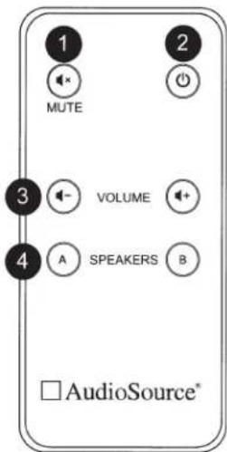
1. Mute
Press this button to mute the AD3002 output.
2. Power/Standby
Press this button to bring the AD3002 out of Standby Mode, or to put the Amplifier in Standby Mode.
3. Volume +/- Controls
Controls the Volume Trim of the Amplifier the same way the front panel Volume Trim does.
4. Speaker A/B switch
Controls A/B selection of the outputs; remotely turn on and off 2 separate sets of speakers.
STEREO SETUP
In this configuration, the mode switch is set to "Stereo". Connect the line out jacks from a stereo pre-amplifier or source to the MAIN input jacks of your AD3002. Next connect your speakers to the terminals marked "Speaker A" observing proper polarity. Select the "A" speakers using the front panel Speaker Selection buttons. Connect a second (optional) pair of speakers to the terminals marked "Speaker B". If you are connecting 4 speakers to the AD3002 they must be 8 ohm speakers only. Press A and B together to use both sets of speakers.

flowchart
graph TD
    A["IN"] --> B["L"]
    B --> C["OUT"]
    D["R"] --> E["INTERRUPT IN"]
    E --> F["MAIN IN"]
    F --> G["MAIN OUT"]
    style A fill:#f9f,stroke:#333
    style D fill:#f9f,stroke:#333
    style E fill:#ccf,stroke:#333
    style F fill:#ccf,stroke:#333
    style G fill:#ccf,stroke:#333
SETUP FOR MULTIPLE SOURCE
In the multiple source set up, a distributed audio system is connected to the AD3002 as a local amplifier via the MAIN inputs. Normally the distributed audio system will be the audio source for the AD3002. The distributed audio is then passed on to be used by additional amplifiers in the distributed system via the MAIN outputs.

The audio output of a local source, such as an MP3 Player, CD, television, computer, etc., is connected to the AD3002 via the INTERRUPTING inputs, and whenever the local source is active its signal will take priority over the distributed audio signal present at MAIN input. However, the distributed audio signal will still be present at the MAIN input. In this circumstance the audio output of the local source will be heard via the AD3002. Once the local source is turned off or muted, the AD3002 will automatically switch back to the distributed audio system as an audio source, assuming the local source remains inactive. There is a delay ranging from 3 to 15 seconds (based on the "Delay Time" setting) when switching from INTERRUPTING input back to MAIN inputs.
A Note On Distortion
Digital amplifiers distort differently than conventional Class A/B amplifiers. If you hear a clicking or popping sound at high volume levels, this is an indication the AD3002 is distorting. Pushing the amplifier harder than the distortion level may trigger the amplifier's protection circuitry which will turn the output of the amplifier off and engage the red protection LED. If this occurs, you can reset it by cycling the power button. The AD3002 is designed to exceed all power levels stated in this manual by a good margin, so if the amplifier is distorting or it's output protection is engaging, reduce the volume using the rear panel Level Controls.
Impedance Matching Volume Controls
When using Impedance Matching Volume Controls (such as the AudioSource AE100VC), please ensure the switch setting is correct for the number of Volume Controls used. Mis-matching the control can lead to amplifier shutdown. In addition, if the amplifier shuts down momentarily at high volume levels, the maximum wattage is being exceeded by the amplifier and the volume should be reduced. If clicking or popping sounds come from the speakers at high volume, reduce the volume as this is an indication that the amplifier is clipping and at maximum volume.
Using the Rear Level/Front Volume Trim
The AD3002 has rear mounted master level controls and a front panel volume trim control. This setup is intended to allow the user to set a "do not exceed" volume level. To do so, start with the rear panel level controls at minimum. Turn the front panel Volume Trim control to maximum and play music from the chosen source. Slowly turn up the rear panel level controls to the maximum volume needed. Next, turn the front panel volume trim control down (counter-clockwise) by 6 to 10 "Clicks" (each click is a 1dB adjustment). This will allow the front panel volume trim to adjust the output volume by a range of 18dB.
Limited Warranty
AudioSource® warrants its amplifier products against defects in materials and workmanship for a limited period of time. For a period of two years from date of original purchase, we will repair or replace the product, at our option, without charge for parts and labor. Customer must pay all parts and labor charges after the limited warranty period expires. The limited warranty period for factory refurbished products expires after ninety (90) days from date of original purchase.
This limited warranty applies only to purchases from authorized AudioSource® electronics retailers. This limited warranty is extended only to the original purchaser and is valid only to consumers in the United States.
Consumers are required to provide a copy of the original sales invoice from an authorized AudioSource® dealer when making a claim against this limited warranty. This limited warranty only covers failures due to defects in materials or workmanship that occur during normal use. It does not cover failures resulting from accident, misuse, abuse, neglect, mishandling, misapplication, alteration, faulty installation, modification, service by anyone other than AudioSource®, or damage that is attributable to Acts of God. It does not cover costs of transportation to AudioSource® or damage in transit. The customer should return his defective product, freight prepaid and insured, to AudioSource® only after receiving a Return Authorization.
This warranty will become void if the serial number identification has been wholly or partially removed, altered or erased. Repair or replacement under the terms of this warranty does not extend the terms of this warranty. Should a product prove to be defective in workmanship or material, the consumer's sole remedies will be repair or replacement as provided under the terms of this warranty. Under no circumstances shall AudioSource® be liable for loss or damage, direct, consequential or incidental, arising out of the use of or inability to use the product. There are no express warranties other than described above.
CRUTCHFIELD®
Thank you for purchasing your Audiosource amplifier from Crutchfield. The manufactures warranty for this amplifier is 2 years, however thanks to our partnership with Audiosource, this has been extended by Audiosource to 3 years from the original date of purchase. During this timeframe Crutchfield will, at Crutchfield's sole discretion, exchange the amplifier if it is found to be defective. If the amplifier is no longer available, a replacement model of similar features as solely determined by Crutchfield will be substituted.
The cost for the packaging, insurance and return shipping to Crutchfield of the defective amplifier is the responsibility of the purchaser, and the cost of packaging and shipping of the replacement amplifier will be the responsibility of Crutchfield.
Any and all other terms and conditions of the Amplifier's original Audiosource owner's warranty remain in full force, except as modified by this document.
Please contact Crutchfield Customer Service at 1-800-955-9091 if you are experiencing any issues with your Audiosource amplifier and our agents will help diagnose the problem and if the product is found to be defective within the normal stipulations of the manufactures warranty, a repair or replacement will be arranged for a period of 3 years from the original date of purchase.


- CAUTION
- RISK OF ELECTRICAL SHOCK DO NOT OPEN
- CAUTION: TO REDUCE THE RISK OF ELECTRIC SHOCK, DO NOT REMOVE THE COVER. NO USER SERVICABLE PARTS INSIDE. REFER SERVICING TO QUALIFIED PERSONNEL!
- IMPORTANT SAFETY INSTRUCTIONS
- FRONT PANEL CONTROLS
- Power Switch
- Speaker Selector
- Balance
- Volume Trim
- REAR PANEL CONTROLS
- Master Volume Controls
- Bass and Treble Controls
- Interrupting Line Input
- Main Input/Output
- Speaker Level Input/Speaker Level Input Line Select
- Mode Select Switch
- STEREO MODE
- BRIDGED MODE
- BRIDGED MODE-MONO APPLICATION
- Delay Time
- Optical Input
- Power Mode Switch
- 12V TRIGGER
- NORMAL
- Speaker B Output
- Speaker A Output
- SPEAKER TERMINALS - STEREO MODE
- SPEAKER TERMINALS - BRIDGED MODE
- NOTE: Use Class 2 wiring for speaker connections.
- Mains Power Inlet & Fuse Holder
- REMOTE
- Mute
- Power/Standby
- Volume +/- Controls
- Speaker A/B switch
- STEREO SETUP
- SETUP FOR MULTIPLE SOURCE
- A Note On Distortion
- Impedance Matching Volume Controls
- Using the Rear Level/Front Volume Trim
- Limited Warranty
- CRUTCHFIELD®
Brand : AudioSource
Model : AD3002
Category : Receiver