
BG-IPGEAR-PRO - Audio/video converter BZBGear - Free user manual and instructions
Find the device manual for free BG-IPGEAR-PRO BZBGear in PDF.


| Product Type | Audio/Video Converter |
| Model | BG-IPGEAR-PRO |
| Brand | BZBGear |
| Input Connectors | 1x HDMI, 1x 3.5mm Audio |
| Output Connectors | 1x RJ45 Ethernet (PoE), 1x HDMI Loop-through |
| Video Resolution Support | Up to 1080p @ 60Hz |
| Audio Support | Stereo analog, PCM up to 48kHz |
| Transmission Distance | Up to 100m (CAT6) |
| Power Supply | 5V DC, 1A (USB or adapter included) |
| Power Consumption | < 5W |
| Dimensions (LxWxH) | 100 x 80 x 25 mm |
| Weight | 200 g |
| Operating Temperature | 0°C to 45°C |
| Storage Temperature | -20°C to 60°C |
| Housing Material | Aluminum alloy |
| LED Indicators | Power, Link, Data |
| Mounting Options | Desktop or wall-mount (bracket included) |
| Compliance | CE, FCC, RoHS |
| Maintenance | Clean with dry cloth; no liquid cleaners |
| Safety Precautions | Keep away from moisture; do not disassemble |
| Spare Parts Availability | Contact BZBGear support for replacement parts |
| Warranty | 1 year limited warranty |
| Package Contents | Converter, power adapter, HDMI cable, user manual |
Frequently Asked Questions - BG-IPGEAR-PRO BZBGear
User questions about BG-IPGEAR-PRO BZBGear
0 question about this device. Answer the ones you know or ask your own.
Ask a new question about this device
Download the instructions for your Audio/video converter in PDF format for free! Find your manual BG-IPGEAR-PRO - BZBGear and take your electronic device back in hand. On this page are published all the documents necessary for the use of your device. BG-IPGEAR-PRO by BZBGear.
USER MANUAL BG-IPGEAR-PRO BZBGear
withVideoWall&PoESupport
UserManual

TABLEOFCONTENTS
Statement 4
Safety Precaution 4
Introduction 5
Features 6
Controller Packing List 7
Transmitter Packing List 7
Receiver Packing List 7
Optional Accessories (Not Included) 7
Transmitter and Receiver Specifications 8
Transmitter and Receiver Interface Descriptions 9
Transmitter and Receiver DIP Switch ID Settings 11
Controller Technical Specifications 12
Application Diagram 13
Network Switch Selection 13
IR Passthrough 14
Network Connection and System Setup 15
WebControl 16
Mapping 17
Groups 19
Video Wall Setup 21
On Screen Display (OSD) 25
Schedule (OSD) 26
Setup 27
History 30
Account 31
BZBGEARSwitcherControlApplication 32
Troubleshooting 40
Technical Support 41
Warranty 42
Mission Statement 43
Copyright 44
Statement
Please read these instructions carefully before connecting, operating, or configuring this product. Please save this manual for future reference.
SafetyPrecaution
- To prevent damaging this product, avoid heavy pressure, strong vibration, or immersion during transportation, storage, and installation.
- The housing of this product is made of organic materials. Do not expose to any liquid, gas, or solids which may corrode the shell.
- Do not expose the product to rain or moisture.
- To prevent the risk of electric shock, do not open the case. Installation and maintenance should only be carried out by qualified technicians.
- Do not use the product beyond the specified temperature, humidity, or power supply specifications.
- This product does not contain parts that can be maintained or repaired by users. Damage caused by dismantling the product without authorization from BZBGEAR is not covered under the warranty policy.
- Installation and use of this product must strictly comply with local electrical safety standards.
Introduction
The BG-IPGEAR-PRO system is an HDMI 2.0 over IP multicast system with video wall & PoE support that boosts up your video/audio transmission distances up to 120m(396ft) in stunning UHD 4K@60. With cost effective ethernet cables, users can easily extend a UHD video from source devices such as a Blu-ray player, PS5, PC, to a distant display.
Additionally, the BG-IPGEAR-PRO system is HDCP compliant and supports IR and RS-232 pass-through.
The BG-IPGEAR-PRO-C smart controller for the BG-IPGEAR-PRO system provides continuous system monitoring, self-recovery, along with real-time email event notifications and alerts. With a high degree of expandability, a single BG-IPGEAR-PRO-C can manage up to 1024 transmitters and an unlimited number of receivers at once.
The intuitive web-based GUI enables users to drag and drop any source to any display, build custom video walls, and create custom on-screen-display (OSD) messages. Users can also access and manage the system by using the free iOS, Android, Windows, and MAC applications.
Note:A supported gigabit network switch is required for the BG-IPGEAR-PRO system. The system is capable of Point-to-Point, Point-to-Many, and Multicasting. Network switches must support IGMP snooping and jumbo frame/large packet transfer. Multicasting requires a managed gigabit network switch with 802.1Q VLAN functionality to allow for multiple video sources.
Features
●Resolutions up to 4K@60 4:4:4 8 bits
●High Dynamic Range (HDR)*
●HDMI 2.0a compliant
•HDCP 2.2 compliant
- Flexible and scalable UHD video broadcasting: one-to-one, one-to-many & multicasting.
- Each transmitter can multicast up to 1,023 receivers for video wall applications or point-to-point.
●Full frequency, bi-directional IR signal from 20KHz to 60KHz.
●Full duplex RS-232 control up to 115,200 bps.
- Easy dip switch matching for hardcoding multicast group configurations.
- Simultaneous video wall functionality (up to a 5x5 video wall)
- 90° , 180° , and 270° clockwise image rotation in video wall mode.
●KVM support to control remote devices.
○USB flash drive (USBoIP) and keyboard/mouse (KMoIP)**
○USB webcam and USB audio device over IP (HW-USBoIP)***
- Wall mounting housing design for easy and robust installation
Notes:
* Due to the video compression, some distortion in terms of visual perception may happen in HDR modes.
** For KMolP functions:
A. The Tx channel ID must set between 0001 to 0008 (max quantity of Tx devices for KVM support is 8 units)
B. The Rx channel ID must set to ID=0 [↑-↑-↑-↑-↑-↑]
C. Users must click the hotkey three times to switch Tx . (ex. Press the "5" key on the num pad three times to switch to ID=0005(Tx)
*** For HW-USBoIP functions:
A. Do not attach devices other than a USB webcam and USB audio device
B. The Rx's webcam and video signal must come from the same Tx.
ControllerPackingList
- 1x BG-IPGEAR-PRO-C
- 1x Rack-mounting ear set
-
1x DC 5V power supply
-
1x User Manual
- 1x Quick Start Guide
TransmitterPackingList
- 1x IPGEAR-PRO-T
-
1x IR Blaster Cable
-
1x User Manual
- 1x IR Receiver Cable
ReceiverPackingList
- 1x IPGEAR-PRO-T
-
1x IR Blaster Cable
-
1x User Manual
- 1x IR Receiver Cable
OptionalAccessories(NotIncluded)
- BG-VOP-ACC-RM
(Mount bracket for RM10)
- BG-VOP-ACC-RM10
(4RU rack mount fits 10 transmitters/receivers)
- BG-VOP-ACC-RB
(Blank mount bracket for RM10)
TransmitterandReceiverSpecifications
| TechnicalSpecifications | |||
| Model | BG-IPGEAR-PRO-T[Tx] | BG-IPGEAR-PRO-R[Rx] | |
| HDMI Compliance | HDMI | ||
| HDCP Compliance | Yes | ||
| Video Support | Up to 4K@60 (4:4:4 8 bits) | ||
| Latency | 2 frames (33 ms) maximum | ||
| HDMI over UTP Transmission [24-bit] | Ultra HD (4K2K60)-120m (396ft) [CAT.X] | ||
| Audio Support | Surround sound (up to 7.1ch) or stereo digital audio | ||
| Input TMDS Signal | 1.2 Volts [peak-to-peak] | ||
| Input DDC Signal | 5 Volts [peak-to-peak, TTL] | ||
| ESD Protection | Human body model - ±15kV [air-gap discharge] & ±8kV [contact discharge] | ||
| IR Pass-Thru | Full-duplex bi-directional | ||
| RS-232 Support | Yes | ||
| Input | 1x HDMI + 2x 3.5mm + 2x USB | 1x RJ45 + 1x HDMI + 2x 3.5mm + S/PDIF | |
| Output | 1x RJ45 + 1x S/PDIF + 2x 3.5mm | 2x 3.5mm + 5x USB | |
| In/ Out | 1x DIN9 | 1x DIN9 | |
| HDMI Source Control | Controllable via IR pass-through from Rx to Tx and from Tx to Rx with IR e | ||
| IR Remote Control | Electro-optical characteristics: = 25° / Carrier frequency: 20-60kHz | ||
| HDMI Connector | Type A [19-pin female] | ||
| Min DIN Connector | DIN-9 | ||
| RJ45 Connector | WE/SS 8P8C with 2 LED indicators | ||
| 3.5mm Connector | Analog audio / IR blaster & IR receiver | ||
| MechanicalSpecifications | |||
| Housing | Metal enclosure | ||
| Dimensions (L x W x H) | Model | 194 x 133 x 28 mm[7.6" x 5.2" x 1. | 194 x 133 x 28 mm[7.6" x 5.2" x 1 |
| Package | 264 x 170 x 77mm[10.3" x 6.7" x 3"] | ||
| Carton | 430 x 358 x 291mm[1'4" x 1'2" x 11.5"] | ||
| Weight | Model | 663g [1.5 lbs] | 644g [1.4 lbs] |
| Package | 1528g [3.4 lbs] | ||
| Mounting | Wall mountable case with screws | ||
| Power Supply | 5V DC/ / 48V POE | ||
| Power Consumption | 6 Watts [max] | 7 Watts [max | |
| Operation Temperature | 0~40°C [32~104°F] | ||
| Storage Temperature | -20~60°C [-4~140°F] | ||
| Relative Humidity | 20~90% RH [no condensation] | ||
TransmitterandReceiverInterfaceDescriptions
TransmitterUnit-BG-IPGEAR-PRO-T
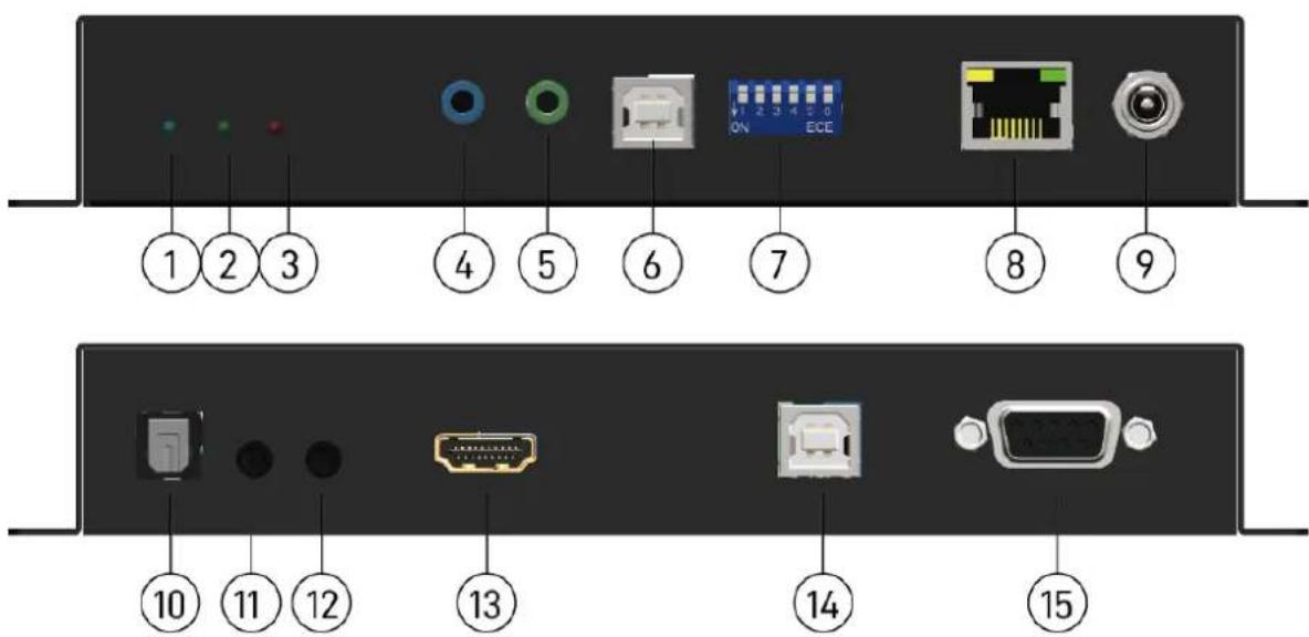
1. PowerLED indicator:
[Blinking] When the unit is connected to power
[Solid] After fully booting and the device has become stable
2.LinkLEDindicator:
[Blinking] When the unit is connected to a Cat-5/5e/6 cable
[Solid] When the transmitting unit connects to an HDMI source and is linked to the receiving unit
-
Info LED indicator: When a user clicks the LED button from the software, the LED light will blink for 30 seconds.
-
IR Blaster: Infrared 3.5mm socket for plugging in the extension cable of IR blaster
-
IR Receiver: Infrared 3.5mm socket for plugging in the extension cable of IR receiver
6.USB:reserved
- DipSwitch: Video channel selection
8.RJ-45:Gigabit Ethernet port
9.+5VDC:Connect to 5V DC power supply
10.S/PDIF:Reserved
-
Analogaudiolinein: Connect to audio source
-
Analogaudiolineout: Connect to headphones
13.HDMIIN:Connects to an HDMI source with an HDMI cable
- USB: Connect to USB host (keyboard/mouse & USB flash driver function)
15.RS-232:Connect to PC serial port with a DSUB-9 cable
ReceiverUnit-BG-IPGEAR-PRO-R

1.PowerLEDindicator:
[Blinking] When the unit is connected to power
[Solid] After fully booting and the device has become stable
2.LinkLEDindicator:
[Blinking] When the unit is connected to a Cat-5/5e/6 cable
[Solid] When the transmitting unit connects to an HDMI source and is linked to the receiving unit
3.InfoLEDindicator:When a user clicks the LED button from the software, the LED light will blink for 30 seconds.
4.IRBlaster:Infrared 3.5mm socket for plugging in the extension cable of IR blaster
5.IRReceiver:Infrared 3.5mm socket for plugging in the extension cable of IR receiver
6.USB(USB2.0port):reserved
- DipSwitch: Video channel selection
8.RJ-45:Gigabit Ethernet port
9.+5VDC:Connect to 5V DC power supply
10.S/PDIF:Reserved
11.Analogaudiomicin(forunicastonly):Connect to microphone
12.Analogaudiolineout:Connect to headphones
13.HDMIOUT:Connect to an HDMI display with an HDMI cable.
14.USB(USB1.1port):Connect to keyboard/mouse
15.USB(USB2.0port):Connect to USB flash drive or webcam
16.RS-232:Connect to PC serial port with a DSUB-9 cable
TransmitterandReceiverDIPSwitchIDSettings
Notes:
- For ID=1\~63 refer to the table below to set up device hardware control.
- For ID=64\~1023, adjust the DIP switches to ID=0 and the ID will be decided by the controller.
| ID | Pin1 | Pin2 | Pin3 | Pin4 | Pin5 | Pin6 |
| 0 | ↑ | ↑ | ↑ | ↑ | ↑ | ↑ |
| 1 | ↓ | ↑ | ↑ | ↑ | ↑ | ↑ |
| 2 | ↑ | ↓ | ↑ | ↑ | ↑ | ↑ |
| 3 | ↓ | ↓ | ↑ | ↑ | ↑ | ↑ |
| 4 | ↑ | ↑ | ↓ | ↑ | ↑ | ↑ |
| 5 | ↓ | ↑ | ↓ | ↑ | ↑ | ↑ |
| 6 | ↑ | ↓ | ↓ | ↑ | ↑ | ↑ |
| 7 | ↓ | ↓ | ↓ | ↑ | ↑ | ↑ |
| 8 | ↑ | ↑ | ↑ | ↓ | ↑ | ↑ |
| 9 | ↓ | ↑ | ↑ | ↓ | ↑ | ↑ |
| 10 | ↑ | ↓ | ↑ | ↓ | ↑ | ↑ |
| 11 | ↓ | ↓ | ↑ | ↓ | ↑ | ↑ |
| 12 | ↑ | ↑ | ↓ | ↓ | ↑ | ↑ |
| 13 | ↓ | ↑ | ↓ | ↓ | ↑ | ↑ |
| 14 | ↑ | ↓ | ↓ | ↓ | ↑ | ↑ |
| 15 | ↓ | ↓ | ↓ | ↓ | ↑ | ↑ |
| 16 | ↑ | ↑ | ↑ | ↑ | ↓ | ↑ |
| 17 | ↓ | ↑ | ↑ | ↑ | ↓ | ↑ |
| 18 | ↑ | ↓ | ↑ | ↑ | ↓ | ↑ |
| 19 | ↓ | ↓ | ↑ | ↑ | ↓ | ↑ |
| 20 | ↑ | ↑ | ↓ | ↑ | ↓ | ↑ |
| 21 | ↓ | ↑ | ↓ | ↑ | ↓ | ↑ |
| 22 | ↑ | ↓ | ↓ | ↑ | ↓ | ↑ |
| 23 | ↓ | ↓ | ↓ | ↑ | ↓ | ↑ |
| 24 | ↑ | ↑ | ↑ | ↓ | ↓ | ↑ |
| 25 | ↓ | ↑ | ↑ | ↓ | ↓ | ↑ |
| 26 | ↑ | ↓ | ↑ | ↓ | ↓ | ↑ |
| 27 | ↓ | ↓ | ↑ | ↓ | ↓ | ↑ |
| 28 | ↑ | ↑ | ↓ | ↓ | ↓ | ↑ |
| 29 | ↓ | ↑ | ↓ | ↓ | ↓ | ↑ |
| 30 | ↑ | ↓ | ↓ | ↓ | ↓ | ↑ |
| 31 | ↓ | ↓ | ↓ | ↓ | ↓ | ↑ |
ControllerTechnicalSpecifications
| Technical | ||
| Role of usage | System Controller | |
| Input | 1x RJ-45 | |
| Output | 1x HDMI | |
| HDMI connector | Type A [19-pin female] | |
| RJ-45 connector | WE/SS 8P8C | |
| Mechanical | ||
| Housing | Metal enclosure | |
| Dimensions[L x W x H] | Model | 90 x 78 x 29mm [3.5" x 3" x 1.1"] |
| Package | 198 x 137 x 74mm [7.8" x 5.4" x 2.9"] | |
| Carton | 420 x 400 x 300mm [1'4"x 1'3" x 11.8"] | |
| Weight | Model | 222g[0.4 lbs] |
| Package | 493g [1 lbs] | |
| Fixedness | Rack-mount with ears | |
| Power supply | 5V DC | |
| Power consumption | 3.5 Watts [max] | |
| Operation temperature | 0~40°C [32~104°F] | |
| Storage temperature | -20~60°C [-4~140°F] | |
| Relative humidity | 20~90% RH [no condensation] | |
ControllerInterfaceDescriptions
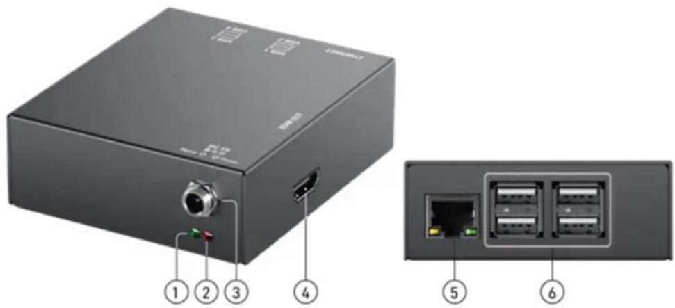
-
Activity LED indicator: When the device is being used, the light will blink.
-
Power LED indicator: When the unit connects to power the light will illuminate.
3.+5VDC:+5V DC power jack.
- Output: HDMI output displays the information of the controller (NOTE: An HDMI cable must be plugged in before powering the unit or no image will be displayed).
5.RJ-45: Ethernet control port
6.USB: Not Used
ApplicationDiagram
![graph TD A["PS5"] --> B["BU-Ray Player"] B --> C["Laptop/PC"] C --> D["Server"] D --> E["BZB2-GEAR"] E --> F["TV wall"] E --> G["TV wall"] E --> H["TV wall"] E --> I["TV wall"] E --> J["TV wall"] E --> K["TV wall"] E --> L["TV wall"] E --> M["TV wall"] E --> N["TV wall"] E --> O["TV wall"] E --> P["…](/content/2026/05/959147/images/a56d0c61c052b3d8c1abe4df75633803a7818de9af3be5464edac905d8e9e1c5.jpg)
NetworkSwitchSelection
1.ChoosingaNetworkSwitch
The selected network switch must support the following functions:
●Gigabit (or faster) ethernet ports
-IGMP Snooping
-IGMP v2 Snooping (multicast)
-IGMP Querier
- IGMP Snooping Fast Leave
- Multicast forwarding or filtering
- Jumbo frames/large packet transfer up to 9KB (9000 bytes)
2.NetworkSwitchConfiguration
Configuring your switch properly so it will pass data more efficiently, please refer to the following settings:
- Enable IGMP Snooping on Layer 2 switches.
- Enable IGMP Querier on the Layer 3 switches.
- Enable IGMP Fast-Leave on all switches that have IPGEAR-PRO units connected directly to them.
- Enable jumbo frame/large packet transfer on the network switch to improve data transfer efficiency.
IRPassthrough
[IRExtenders]
IRBlasterIRReceiver


[IRSockets]
IRBLASTER: Plug in the IR blaster to emit all IR command signals received from the IR receiver from the other end to control the devices corresponding to the IR signals.
IRRECEIVER: Plug in the IR receiver to receive all IR command signals from the IR remote controls of the corresponding devices.
CAUTION!
Incorrect placement of IR Blaster and Receiver may result in the failure of the IR extenders. Please check carefully before plugging in the IR extender to the respective IR sockets. Warranty will not cover the damage.
[DefinitionofIREarphoneJack]
IRBlasterIRReceiver
![1. IR Signal 2. Grounding 1 2 1 23 1. IR Signal [30-56 kHz] 2. Grounding 3. Power](/content/2026/05/959147/images/8ade0270694f57b8fbd0342a9bc446bc7ccfdc6e0e9b2969c1268ea86e79bc38.jpg)
NOTE:Users can buy any IR extension cables on the market that are compatible with the IR sockets and extender for replacement use shown in the diagram above. IR cables longer than 2m (6ft) may not work.
NetworkConnectionandSystemSetup
InstallationSetup
- Connect a Laptop/PC and the BG-IPGEAR-PRO-C into a Gigabit IP Switch/Router/Hub.
a. Ensure your Gigabit IP Switch/Router/Hub has a DHCP server enabled.
b. The BG-IPGEAR-PRO-C controller is preconfigured to be set to DHCP and will automatically grab an IP address from the network. If a DHCP server is not available, the unit will assign itself its own IP. The controller, transmitters, and receivers must all be on the same network/VLAN to communicate properly.
- Plug one end of an HDMI cable into the BG-IPGEAR-PRO-C and the other end into a display.
- Plug power into the control box and wait for the unit to boot and show its information splash screen on the display.
a. NOTE: HDMI must be plugged into the controller before it is powered on otherwise no image will be displayed.

- The splash screen will display the IP Address, Network Mask, Gateway, and URL if the network had DHCP configured properly as shown in the image above.
a. Users can also use a mobile device connected to the same network to scan the QR code on the display to access the web page for management.
- Next, assign each transmitter (BG-IPGEAR-PRO-T) in the system a unique ID by using the DIP switch panel on the side of the unit (for specific DIP switch settings see the previous chart).

- Receivers (BG-IPGEAR-PRO-R) can be set to receive signals from any transmitter or a specific one. To receive signal from any transmitter, leave all dip switches in the 0 position (up). To receive signal only from a specific transmitter, toggle the DIP switches on the receiver to match the positions on the desired transmitter.
- When the dipswitches are set, plug the transmitters and receivers into the PoE network switch to power them on.
a. Connect sources to transmitters and displays to receivers using HDMI cables.
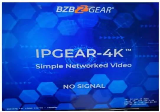
b. When powered, connected to a display, and unpaired from a transmitter the receivers will display the following image:
WebControl
- Type in the URL shown by the BG-IPGEAR-PRO-C into your preferred web browser or scan the QR code using a mobile device connected to the same network as the controller.
- The login page will be displayed if the system and network were configured correctly as shown below.

- Enter the default credentials to login to the system.
a. Default account: admin
b. Default password: admin
Mapping
- Upon logging in you will be taken to the systems Mapping page.

- On this screen users can pair transmitters and receivers together, view and manage presets, as well as view grouped units.
- The image previews on the Mapping page display useful information such as the group/pair ID in the top right, editable device name in the bottom left, and device IP address.

a.


b. The lightbulb symbol will illuminate red when clicked
which will cause the corresponding units red LED indicator light to blink for a short period of time to assist with identification.
c. On transmitting units the paired symbol shows the number of receivers that the transmitter is currently broadcasting too.

d. On receiver units the ON/OFF buttons send CEC commands to compatible displays to turn them on or off.
- To set a configuration as a preset click "Save as" dropdown and select the desired preset location. To recall a preset click the "Recall" drop down and select a preset that has been previously saved.

- To select a set of grouped transmitters or receivers select the drop down at the top of each respective section.

a. Selecting a group of transmitters or receivers will make the system display only units in that group for easier identification and management.
Groups
Transmitters or receivers can be grouped together for easier identification and system management. To create or manage device groups select the “Group” tab from the menu on the left hand side of the web interface.
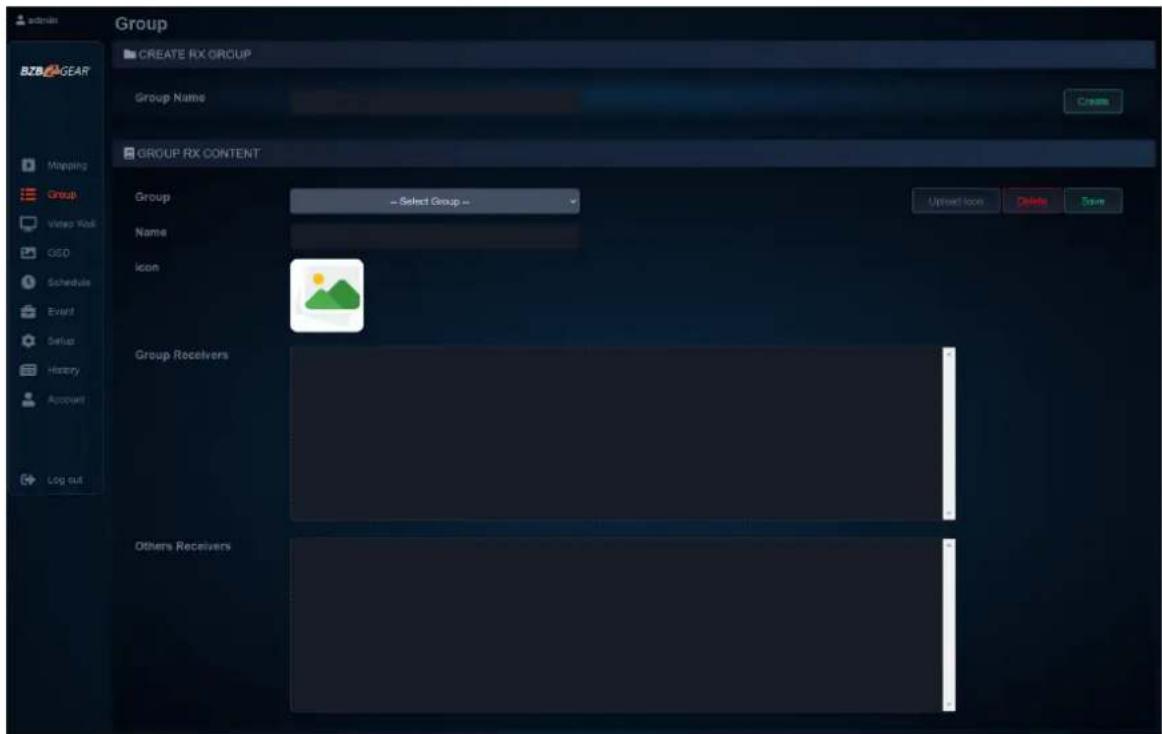
- To create a receiver or transmitter group, type in a "Group Name" and click "Create."

- Once the group is created, move to the next section on the screen and select the group name you just created from the "Group" dropdown menu.
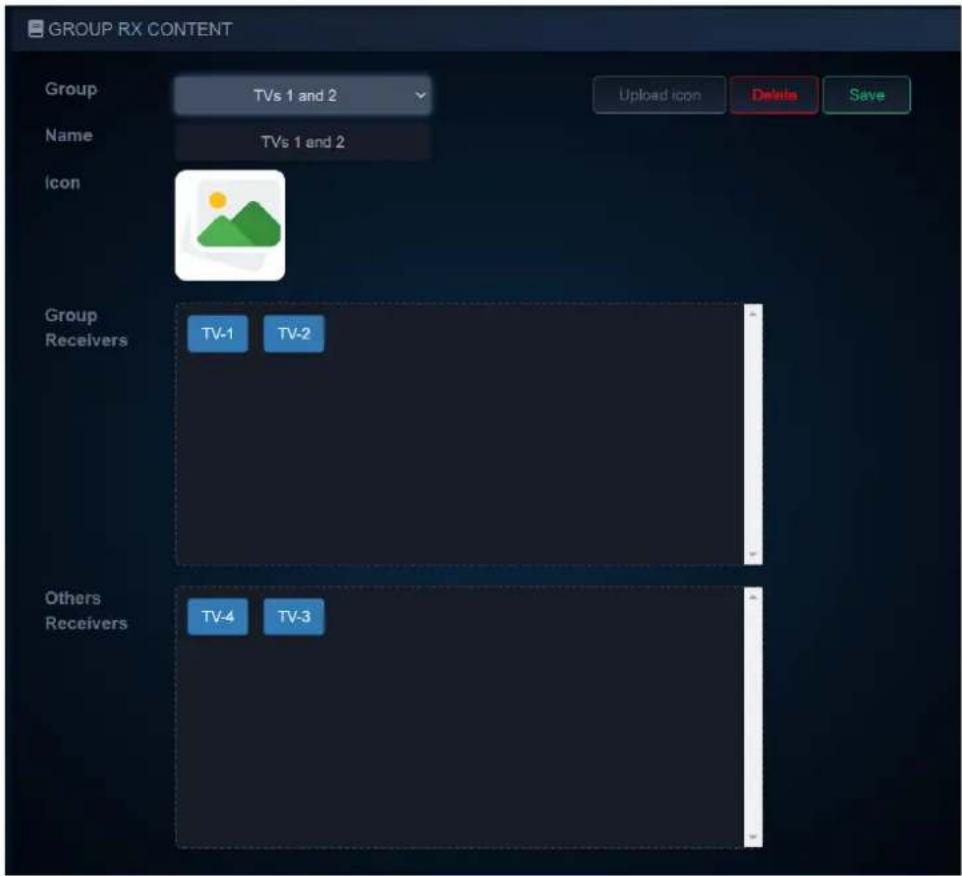
a.
b. Click and drag devices from the bottom "Others" box to the "Group" box above.

- Users can also choose to upload an icon for the group to assist with identification.
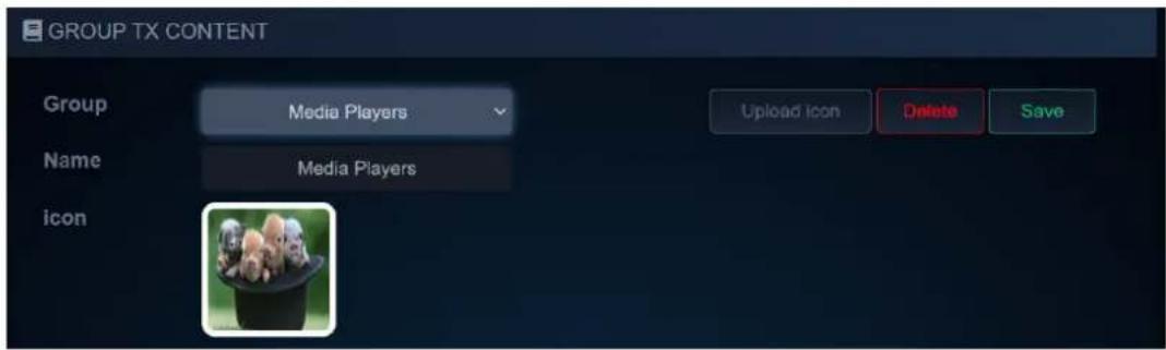
a. Click the "Upload icon" button to choose an image to upload for the group. Note: Group images must be .png or .jpg file formats and no larger than 1920x1080.

b.
- When you are done editing the group, click the "Save" button to save the group.

a.
- The grouped device can now be filtered on the Mapping page using their respective drop down menus.
VideoWallSetup
The BG-IPGEAR-PRO system is capable of forming multiple video walls simultaneously (maximum size 6x6 or 36 displays). To create a video wall select the "Video Wall" tab from the left hand menu.
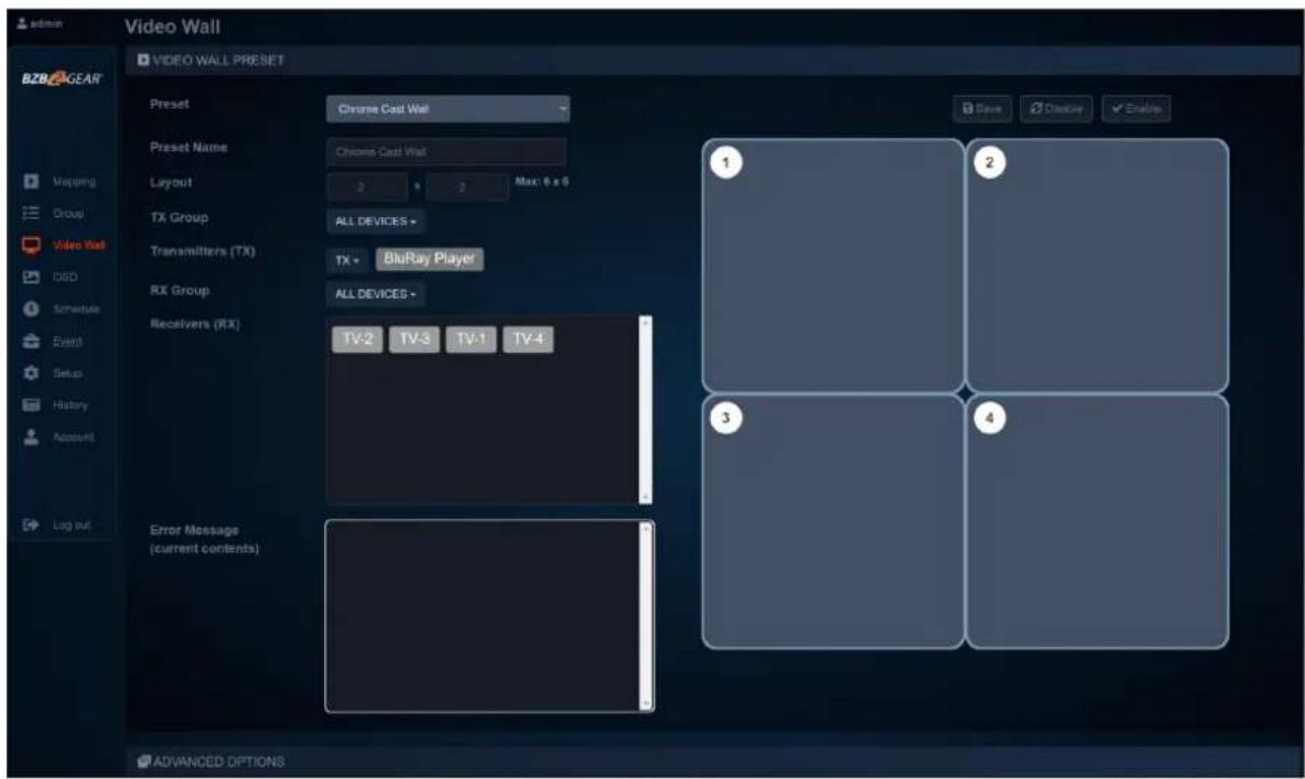
- To create or edit a video wall select a Preset from the dropdown menu

- Users can edit the video wall "Preset Name" by typing in a desired name in the text field.
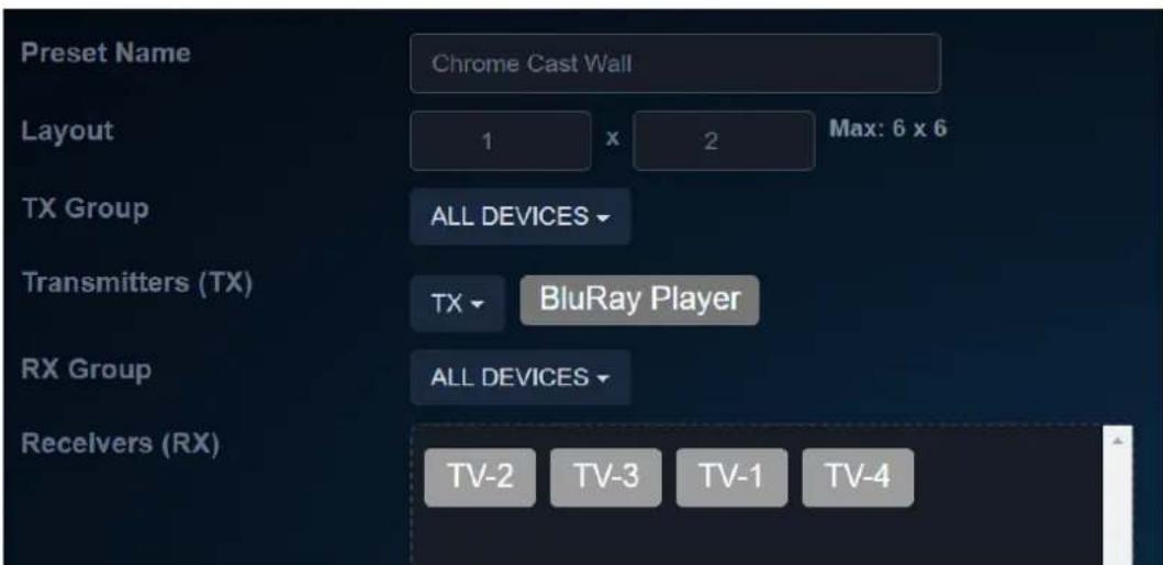
- To edit the size of the video wall adjust the number of rows and columns up to a maximum of 6x6.
a. If you have previously created device groups use the "TX Group" and "RX Group" dropdowns to filter your selection
-
Select a Transmitter from the "TX" dropdown that will act as the source device for the video wall.
-
Click and drag receivers to their respective spot on the video wall to coordinate with the display position.
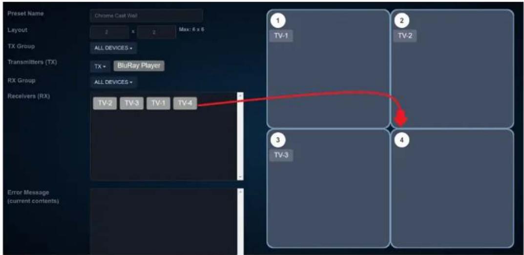
- Once your receivers are placed in their position on the wall click "Save" to save the video wall layout. Press "Enable" to start the video wall feed and "Disable" to stop the video wall.

BezelAdjustments
- To adjust the bezel alignment of a display on the video wall users can use the quick options by clicking the display name shown under the position number or Advanced Options which requires measuring the display but can be more accurate..

c. Use the sliders to adjust the bezel alignment of the selected screen.
i. Forverticaledgespositive values shift the image up and negative values shift the image down.
ii. For horizontal edges positive values shift the image to the right and negative values shift the image to the left.
d. Click "Apply" to finalize the bezel adjustment changes for the selected screen.
e. Repeat these steps for each screen in the video wall as necessary.
The "AdvanceOptions" section allows for even greater control of bezel adjustment.

-
Select a Receiver from the "RX List" and use the diagram to the right to assist with taking measurements of the display. All measurements are in millimeters (mm).
-
Define the layout of the wall and the display placement on the wall by entering its row and column. (The top left display in the video wall (TV 1) will be at Row Position 0, Column Position 0.)
-
OW and OH represent Outside Width and Outside Height. These measurements should be obtained by measuring from the outside edges of the display frame (bezel).
-
VW and VH represent Video Width and Video Height. These measurements should be obtained by measuring from the edges of the image area of the display (usually the inside edge of the bezel).
-
Click "Apply" to finalize changes for the display.
OnScreenDisplay(OSD)
The OSD menu allows users to brand video streams with a image or text overlay.
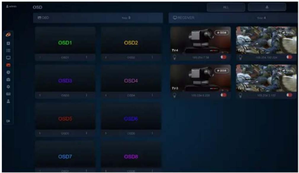
- Users can upload their own.jpg or .png with a 1920*1080 resolution by clicking the
upload button in the top rig
- By clicking the settings icon (3 dots) beneath one of the OSD windows users can adjust the message text, image selection, transparency, position, color, and size.

- Click and drag the desired image/text from the OSD panel to the receiver of your choice on the right. Use the red/green toggle on the bottom of each receiver to either display or hide the OSD image on the unit.
Schedule(OSD)
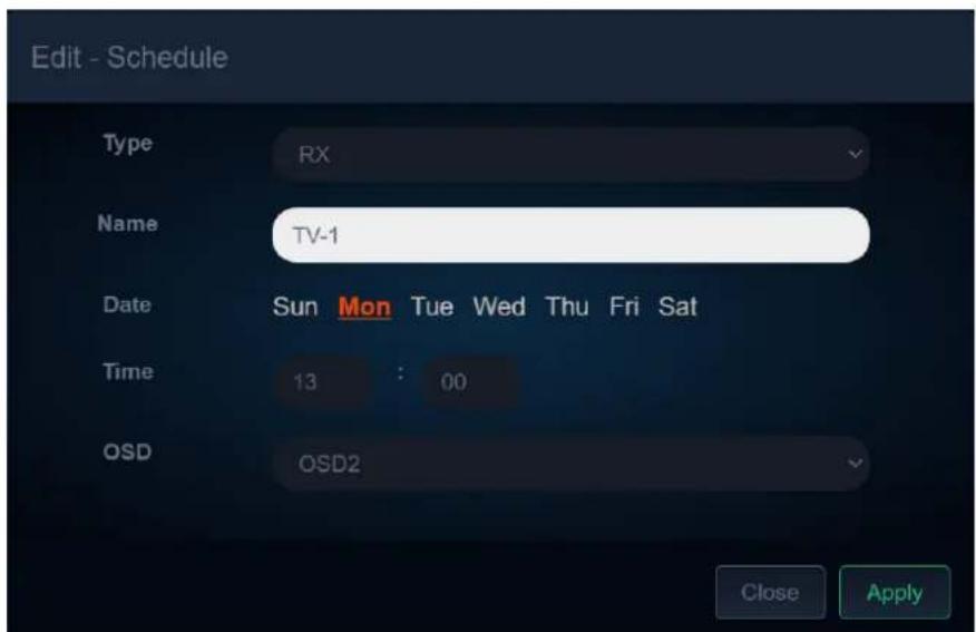
The Schedule (OSD) tab allows users to set a day and time for a message to automatically appear on a screen.

Event
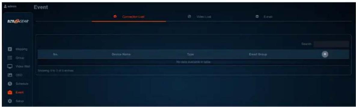
Using the event feature, users can set the system to automatically send notifications in the event of video loss or a system device going offline, helping administrators efficiently manage the system.
Setup
After connected BG-IPGEAR-PRO transmitters and receivers are discovered by the control unit, the devices will be visible on the “Setup” tab under the “Devices” page. This page refreshes every 10 seconds automatically.
The Status page includes the device's Group ID, Name, IP Address, MAC Address, and uptime.


By clicking the green pencil icon users can edit settings of a particular transmitter or receiver.
ReceiverSetup
From the Receiver Setup screen users can view device information and edit its settings.

- Name- Edits the device's name.
- StreamingVideo- Mutes the receiver's video output.
- Scaling- Scales the output resolution to match a connected display.
- Rotate - Rotates the output image for video walls and digital signage applications.
- RS232BaudRate- Sets the baud rate for RS232 signal extension
TransmitterSetup
From the Transmitter Setup screen users can view device information and edit its settings.

- Name— Edits the device's name.
- Group ID – Edits the device's Group ID. It is recommended that users allow the system to automatically assign the Group ID.
- StreamingVideo- Mutes the transmitter's video output stream.
- Loop-Out- Enable/Disable the HDMI Loop-Out port.
- Bit Rate – Limits the transmitter's output data rate. It is recommended that users leave this setting on Auto. Compressing the output signal can result in video artifacts if done incorrectly. The system should be installed with sufficient bandwidth available for the signal to be transmitted without additional compression.
- RS232BaudRate- Sets the baud rate for RS232 signal extension
History
The History tab displays a list of recent system events for a specified date range (up to 500 entries). The event history can be cleared by clicking the red trash icon or exported by hitting the blue download button in the top right.

Account
The Account page allows Admin users to change passwords, create other admin or standard user accounts, and set device permissions.

Standard users do not have access to control or edit video walls or OSD messages. They can also be restricted to access/manage certain transmitters or receivers visible to the system by using the toggle switches in the Device Permissions section.
BZBGEARSwitcherControlApplication
A switcher control application developed by BZBGEAR specifically for our products is available to control the IPGEAR-PRO system. It is available for iOS, MAC, PC, and can be found on the controller product page on our website or via the Windows or Apple app stores.
AddingaDevicetotheSwitcherControlApplication
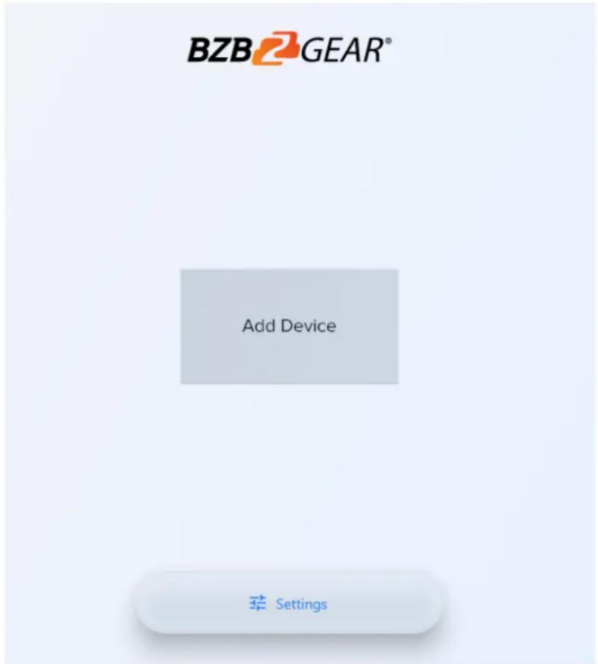
After installing the app on your device and opening it, you will be navigated to the “Add Device” screen. Click the “Add Device” button to begin adding a device.
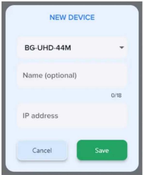
From the “New Device” popup, select your device you wish to control from the model selection drop down. Type in a name for easy identification (optional). Next, type in the IP address of the device you wish to control. For the IPGEAR PRO system the IP address can be found on the splash screen of the controller when it is connected to a display via HDMI.
Click "Save" and you will be navigated automatically back to the "Add Device" screen where your system should now be viewable and selectable if added correctly.

MappingontheSwitcherControlApplication
The control app for the IPGEAR system was designed to function much like the web interface for ease of use.
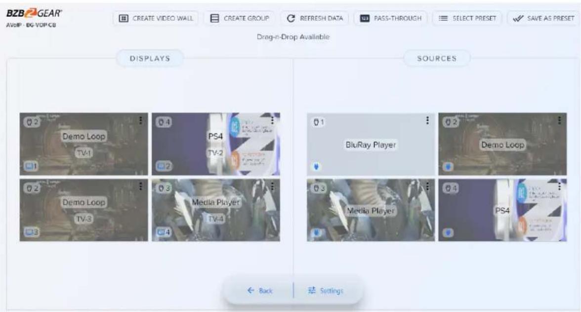
On the main mapping page users can click and drag displays or sources to one another to pair devices together.
Clicking on the in the upper right corner of a display will allow users to change the display name or, if available on the display, send CEC commands to turn the display On or Off.

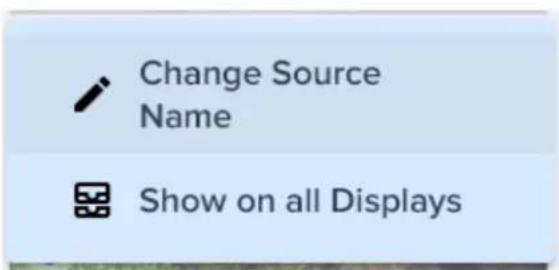
Clicking on the 3 dots on a source device allows users to change the source name or to send the selected source signal to all displays.
CreatingaDeviceGroupusingtheSwitcherControllerApp
For simpler management of larger systems displays and sources can be grouped together for easier identification.
1) From the options on the top of the Mapping page select "Create Group" button to begin creating a group.

CREATE GROUP
2) Next select whether your group is going to for source or display devices.
![graph TD A["be"] --> B["Group creation"] B --> C["Source Group"] B --> D["Displays Group"]](/content/2026/05/959147/images/c2d15547c3b16af669ec130ba3a2d745b1ac56131fce197bc1900d514a907f4d.jpg)
3) Type in a name for your group. (Note group names can only be 18 characters long.

4) Once created your group will appear under its relevant section.

5) Click and drag the displays or sources to the group and they will be moved from the available list into the group folder.
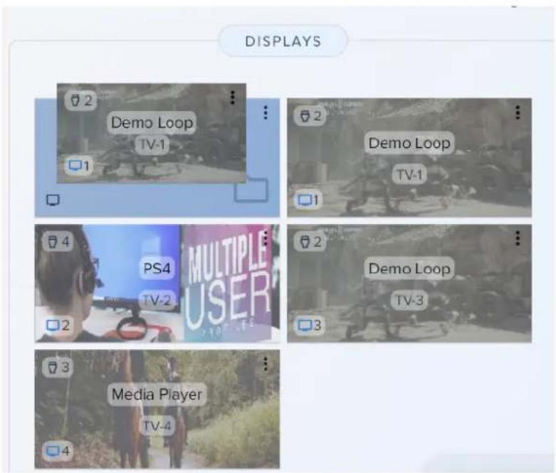
6) Click on the group to view and manage the devices inside. Click "All Devices" to return to the main mapping page to view all groups and/or ungrouped devices.


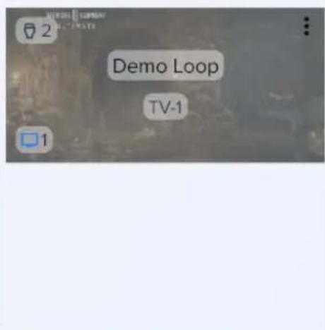
Note:Groups cannot be dragged. However, dragging a source to a "Display Group" will change all display devices in that group to the selected source.
CreatingaVideoWallusingtheSwitcherControllerApp
1) To create a video wall using the Switcher Control app click the "Create Video Wall"
CREATE VIDEO WALL
button at the top of the application.
2) On the Video Wall page click and drag displays to their respective position in the video wall. Note: If a display group has been created it will also be shown here for easier identification. Simply click the group to expand it and show grouped displays.
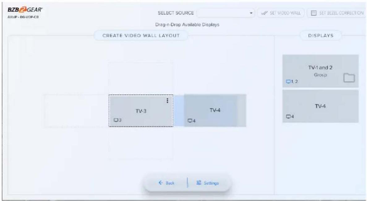
3) Once your displays are positioned correctly on the template, click the "Select Source" drop down at the top of the application to pick a source for the video wall.

4) Once a source is selected click the "Set Video Wall" button to create the video wall.
SELECT SOURCE

Demo Loop


SET VIDEO WALL
5) Use the "Set Bezel Correction" button at the top to adjust
the image on the video wall to compensate for the border on all displays simultaneously.
SET BEZEL CORRECTION

6) To adjust each display individually, select the
in the upper right corner of the display in the video wall and select "Set Bezel Correction" from the pop up menu.

Set Bezel Correction

Delete
7) Move the sliders to adjust the image to compensate for the TV bezel/frame.

8) Return to the main mapping page by clicking the "Back" button at the bottom.

Back

Settings
The video wall can now be viewed under the display section of the mapping page. To change the source of the video wall simply drag a source device to the Video Wall.

SwitcherControlApplicationPresets
To save a mapping configuration as a preset select the "Save as Preset" button in the top right corner.

SAVE AS PRESET
Select the preset position you wish to save. Click the to rename the preset if desired.
To recall a saved preset click the "Select Preset"

SELECT PRESET
button and then select your desired
preset from the menu.
Select Preset to Save Configuration
○ Preset 1 ⋮
○ Preset 2 ⋮
○ Preset 3
○ Preset 4
○ Preset 5 ⋮
○ Preset 6 ⋮
○ Preset 7 ⋮
○ Preset 8
○ Preset 9 :
Cancel
Save
Troubleshooting
1) Noimage/splashscreenfromcontrolbox:
a) Ensure HDMI and ethernet cables are plugged in and power cycle the control box.
2) Transmittersorreceiversarenotpopulatinginthecontrolsoftware/web interface.
a) Power cycle the transceivers by unplugging their ethernet cable and ensure the control box is plugged into the same network/VLAN as the transceivers.
b) Factory reset the transceiver by logging into the unit via its IP address displayed on screen while in receiver mode.
3)Imagewillnotdisplayfromthereceiverunit.
a) Ensure the receiver is paired with a transmitter unit.
b) Ensure HDMI is plugged into the output port on the transceiver.
c) Ensure resolution is set on the receiver unit in settings to match the display it is connected to (4K2K will not display on a 1080p TV).
4) Image previewsonthemappingpagearenotupdatingcorrectly.
a) Clear your browser cache and restart your browser.
5) Transmitter will not pair with another device or are receiver will only pair to one transmitter.
a) Ensure transmitters are set to a unique ID using the dipswitch panel.
b) Ensure the receiver dipswitch panel is set to 0 for all switches.
TechnicalSupport
Have technical questions? We may have answered them already!
Please visit BZBGEAR's support page (bzbgear.com/support) for helpful information and tips regarding our products. Here you will find our Knowledge Base (bzbgear.com/knowledge-base) with detailed tutorials, quick start guides, and step-by-step troubleshooting instructions. Or explore our YouTube channel, BZB TV (youtube.com/c/BZBTVchannel), for help setting up, configuring, and other helpful how-to videos about our gear.
Need more in-depth support? Connect with one of our technical specialists directly:
Phone
1.888.499.9906
support@bzbgear.com
LiveChat
bzbgear.com
Warranty
BZBGEAR Pro AV products and cameras come with a three-year warranty. An extended two-year warranty is available for our cameras upon registration for a total of five years.
For complete warranty information, please visit_bzbgear.com/warranty.
For questions, please call 1.888.499.9906 or email support@bzbgear.com.
MissionStatement
BZBGEAR is a breakthrough manufacturer of high-quality, innovative audiovisual equipment ranging from AVoIP, professional broadcasting, conferencing, home theater, to live streaming solutions. We pride ourselves on unparalleled customer support and services. Our team offers system design consultation, and highly reviewed technical support for all the products in our catalog. BZBGEAR delivers quality products designed with users in mind.
Copyright
All the contents in this manual and its copyright are owned by BZBGEAR. No one is allowed to imitate, copy, or translate this manual without BZBGEAR's permission. This manual contains no guarantee, standpoint expression or other implies in any form. Product specification and information in this manual is for reference only and subject to change without notice.
Allrightsreserved. No reproducing is allowed without acknowledgement.


- Tableofcontents
- Statement
- Safetyprecaution
- Introduction
- Features
- Notes
- Controllerpackinglist
- Transmitterpackinglist
- Receiverpackinglist
- Optionalaccessories(notincluded)
- Transmitterandreceiverspecifications
- Transmitterandreceiverinterfacedescriptions
- Powerled indicator
- 2.LinkLEDindicator
- 1.PowerLEDindicator
- Transmitterandreceiverdipswitchidsettings
- Controllertechnicalspecifications
- Controllerinterfacedescriptions
- Applicationdiagram
- Networkswitchselection
- 1.ChoosingaNetworkSwitch
- 2.NetworkSwitchConfiguration
- Irpassthrough
- [Irsockets]
- Caution
- Networkconnectionandsystemsetup
- Installationsetup
- Webcontrol
- Mapping
- 0017
- 1000
- 0013
- 0004
- Groups
- Videowallsetup
- Bezeladjustments
- Onscreendisplay(osd)
- Schedule(osd)
- Event
- Setup
- Receiversetup
- Transmittersetup
- History
- Account
- Bzbgearswitchercontrolapplication
- Addingadevicetotheswitchercontrolapplication
- Mappingontheswitchercontrolapplication
- Creatingadevicegroupusingtheswitchercontrollerapp
- Creatingavideowallusingtheswitchercontrollerapp
- Switchercontrolapplicationpresets
- Troubleshooting
- Noimage/splashscreenfromcontrolbox
- Transmittersorreceiversarenotpopulatinginthecontrolsoftware/web interface
- 3)Imagewillnotdisplayfromthereceiverunit
- Image previewsonthemappingpagearenotupdatingcorrectly
- Transmitter will not pair with another device or are receiver will only pair to one transmitter
- Technicalsupport
- Phone
- Livechat
- Warranty
- Missionstatement
- Copyright
Brand : BZBGear
Model : BG-IPGEAR-PRO
Category : Audio/video converter