ET65 - Tablet Xplore - Free user manual and instructions
Find the device manual for free ET65 Xplore in PDF.


| Product Type | Rugged Tablet |
| Brand | Xplore |
| Model | ET65 |
| Dimensions | 305 x 200 x 25 mm |
| Weight | 1.5 kg |
| Display | 10.1-inch touchscreen, 1920x1200 |
| Processor | Intel Core i5-7300U |
| RAM | 8 GB DDR4 |
| Storage | 256 GB SSD |
| Operating System | Windows 10 Pro |
| Battery | Hot-swappable, up to 12 hours |
| Power Supply | 12V DC, 2.5A |
| Connectivity | Wi-Fi 802.11ac, Bluetooth 4.2, LTE optional |
| Ports | USB 3.0, HDMI, RJ45, audio jack |
| Protection Level | IP65, MIL-STD-810G |
| Camera | 8 MP rear, 2 MP front |
| GPS | GPS, GLONASS |
| Maintenance | Clean with a damp, lint-free cloth |
| Safety | Do not expose to extreme temperatures |
| Spare Parts | Available through Xplore service centers |
Frequently Asked Questions - ET65 Xplore
User questions about ET65 Xplore
0 question about this device. Answer the ones you know or ask your own.
Ask a new question about this device
Download the instructions for your Tablet in PDF format for free! Find your manual ET65 - Xplore and take your electronic device back in hand. On this page are published all the documents necessary for the use of your device. ET65 by Xplore.
USER MANUAL ET65 Xplore
ZEBRA and the stylized Zebra head are trademarks of Zebra Technologies Corporation, registered in many jurisdictions worldwide. All other trademarks are the property of their respective owners. ©2023 Zebra Technologies Corporation and/or its affiliates. All rights reserved.
Information in this document is subject to change without notice. The software described in this document is furnished under a license agreement or nondisclosure agreement. The software may be used or copied only in accordance with the terms of those agreements.
For further information regarding legal and proprietary statements, please go to:
SOFTWARE: zebra.com/linkoslegal.
COPYRIGHTS: zebra.com/copyright.
PATENTS: ip.zebra.com.
WARRANTY: zebra.com/warranty.
END USER LICENSE AGREEMENT: zebra.com/eula.
Terms of Use
Proprietary Statement
This manual contains proprietary information of Zebra Technologies Corporation and its subsidiaries (“Zebra Technologies”). It is intended solely for the information and use of parties operating and maintaining the equipment described herein. Such proprietary information may not be used, reproduced, or disclosed to any other parties for any other purpose without the express, written permission of Zebra Technologies.
Product Improvements
Continuous improvement of products is a policy of Zebra Technologies. All specifications and designs are subject to change without notice.
Liability Disclaimer
Zebra Technologies takes steps to ensure that its published Engineering specifications and manuals are correct; however, errors do occur. Zebra Technologies reserves the right to correct any such errors and disclaims liability resulting therefrom.
Limitation of Liability
In no event shall Zebra Technologies or anyone else involved in the creation, production, or delivery of the accompanying product (including hardware and software) be liable for any damages whatsoever (including, without limitation, consequential damages including loss of business profits, business interruption, or loss of business information) arising out of the use of, the results of use of, or inability to use such product, even if Zebra Technologies has been advised of the possibility of such damages. Some jurisdictions do not allow the exclusion or limitation of incidental or consequential damages, so the above limitation or exclusion may not apply to you.
About This Guide
This guide provides information about using the device and accessories.

NOTE: All windows pictured in this guide are samples and can differ from actual screens.
Notational Conventions
The following conventions are used in this document:
- Bold text is used to highlight the following:
- Dialog box, window, and screen names
- Dropdown list and list box names
- Checkbox and radio button names
- Icons on a screen
• Key names on a keypad - Button names on a screen
- Bullets (•) indicate:
- Action items
• List of alternatives - Lists of required steps that are not necessarily sequential.
- Sequential lists (for example, those that describe step-by-step procedures) appear as numbered lists.
Icon Conventions
The documentation set is designed to give the reader more visual clues. The following visual indicators are used throughout the documentation set.

NOTE: The text here indicates information that is supplemental for the user to know and that is not required to complete a task.

IMPORTANT: The text here indicates information that is important for the user to know.

CAUTION: If the precaution is not heeded, the user could receive a minor or moderate injury.
About This Guide

WARNING: If danger is not avoided, the user CAN be seriously injured or killed.

DANGER: If danger is not avoided, the user WILL be seriously injured or killed.
Service Information
If you have a problem with your equipment, contact Zebra Global Customer Support for your region. Contact information is available at: zebra.com/support.
When contacting support, please have the following information available:
- Serial number of the unit
- Model number or product name
- Software type and version number
Zebra responds to calls by email, telephone, or fax within the time limits set forth in support agreements.
If your problem cannot be solved by Zebra Customer Support, you may need to return your equipment for servicing and will be given specific directions. Zebra is not responsible for any damages incurred during shipment if the approved shipping container is not used. Shipping the units improperly can possibly void the warranty.
If you purchased your Zebra business product from a Zebra business partner, contact that business partner for support.
Getting Started
This section explains how to set up the device for the first time.
Unpacking the Device
After receiving the package, remove the tablet from the box.
- Carefully remove all protective material from the device and save the shipping container for later storage and shipping.
- Verify that the following were received:
- ET6x Tablet
• Regulatory Guide
- Inspect the equipment for damage. If any equipment is missing or damaged, contact the Global Customer Support center immediately.
- Prior to using the device for the first time, remove the protective shipping film that covers the scan window and display.
Features
This section lists the features of the ET6x tablet.

NOTE:
Tablets with Touch Screen Heater have a blue line around the display.
Battery-free tablets have a blank battery pack installed for water and dust sealing.
Figure 1 ET6x Front View
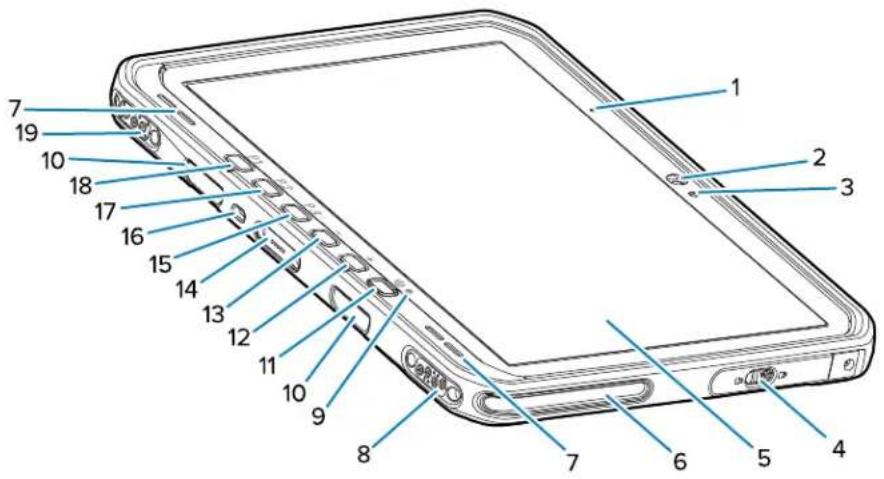
Table 1 Front View
| Number Item | Description | |
| 1 Front microphone | Use for voice communications or | audio recordings. |
| 2 Front camera | Use for video conferencing. | |
| 3 Light sensor | Determines ambient light for controlling | display backlight intensity. |
| 4 Access door | Secure door for accessing USB ports | (two USB-A and one USB-C). |
| 5 Touch screen | Displays all information needed to operate the device. | |
| 6 Dock alignment | slot Assists in aligning the tablet with the dock. | |
| 7 Speakers Provides audio output. | ||
| 8 Dock USB connector | Provides USB communication through the dock. | |
| 9 Charging indicator | Indicates power state and battery charging status while charging and application-generated notifications. | |
| 10 Keyboard/Shoulder strap mount slots | Provides alignment and mounting of keyboard and shoulder strap clips. | |
| 11 | Power button | Turns the display on and off. Press and release to turn on the device. Press and hold to restart the device or power it off. |
| 12 Volume up button | Increases the audio volume. | |
| 13 Volume down button | Decreases the audio volume. | |
| 14 Keyboard interface connector | Provides power and communication with the keyboard. | |
| 15 P3 button | Programmable button (PTT - default). | |
| Number Item Description | ||
| 16 Kensington security slot Provides mounting a security cable to prevent theft or unauthorized use of the tablet. | ||
| 17 P2 button Programmable button (Home - default). | ||
| 18 P1 button Programmable button (Back - default). | ||
| 19 Dock Power / Antenna connector Provides power and antenna connection through the dock. | ||
Figure 2 USB Ports
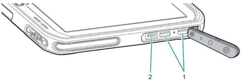
Table 2 USB Ports
| Number Item Description | |
| 1 USB-A port Provides communication with accessories such as scanners. | |
| 2 USB-C port Provides communication with a host computer and charging. | |
Figure 3 ET6x Back View
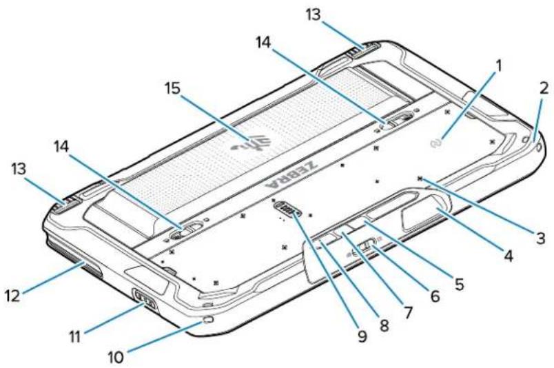
Getting Started
| Number Item | Description | |
| 1 NFC antenna | Use to read NFC cards. | |
| 2 Stylus mount | Provides mounting for a stylus tether. | |
| 3 Accessory mount | point locations Indicates mounting | location points on polymer film for accessory captive screws. CAUTION: Do not remove the polymer film. |
| 4 Scanner exit window | window Provides data capture using the imager. | |
| 5 Rear camera | Autofocus camera that takes photos, | captures barcode data, and reads OCR data. |
| 6 Front camera | privacy cover switch | Use to cover the front camera when not in use. |
| 7 Rear camera | LED flash Provides illumination for the camera. | |
| 8 Rear microphone | Use for audio recordings. | |
| 9 Communication | expansion port Provides USB comm | munication and power to an accessory. |
| 10 Stylus mount | Provides mounting for a stylus tether. | |
| 11 Scan button | Initiates barcode data capture when a scan-enabled application is active. | |
| 12 Dock alignment | slot Assists in aligning the tablet with the dock. | |
| 13 | Dock locking mechanism | Secures the tablet in a dock. |
| 14 | Battery release latches | Releases the battery. |
| 15 | Battery Blank Battery Pack | Provides power to the tablet. Provides water and dust sealing when used in fixed mount installation when a battery is not required. |
Setting Up the Device
To start using the device for the first time:

NOTE: The ET6x with a battery ships in Ship Mode to prevent discharging during shipment and storage. To remove the tablet from Ship Mode, place the tablet in a powered Vehicle Dock, connect power with a USB cable, or press the power button.
- Install a nano SIM card (optional for ET65 only).
- Install a microSD card (optional).
- Install the battery.
- Charge the device.
Installing the microSD Card
The microSD card slot provides secondary non-volatile storage. The slot is located under the battery. Refer to the documentation provided with the card for more information, and follow the manufacturer's recommendations for use.

CAUTION: Follow proper electrostatic discharge (ESD) precautions to avoid damaging the microSD card. Proper ESD precautions include but are not limited to, working on an ESD mat and ensuring that the operator is properly grounded.
- Slide the battery release latches toward the sides of the tablet.
The battery ejects slightly.
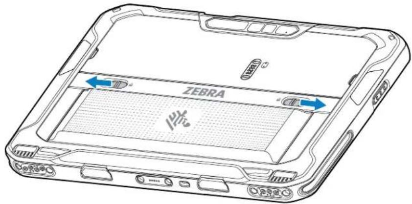
- Lift the battery out of the tablet.
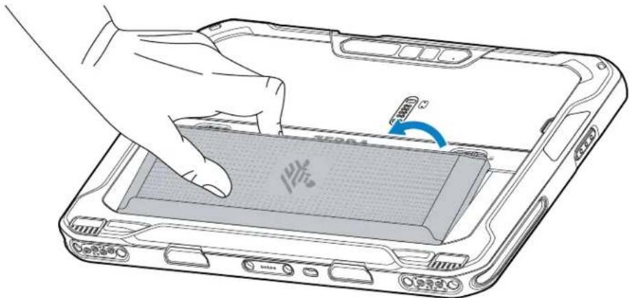
Getting Started
- Remove the access door.

- Slide the microSD card holder to the unlock position.

- Lift the microSD card holder.

- Insert the microSD card into the card holder door, ensuring that the card slides into the holding tabs on each side of the door.

Getting Started
- Close the microSD card holder and lock it into position.
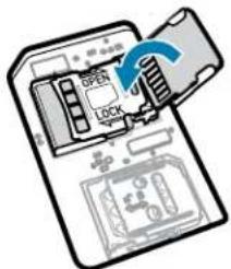


NOTE: To ensure proper device sealing, the access door must be replaced and securely seated.
- Replace the access door.

Getting Started
- Insert the battery, bottom first, into the battery compartment at the back of the device.
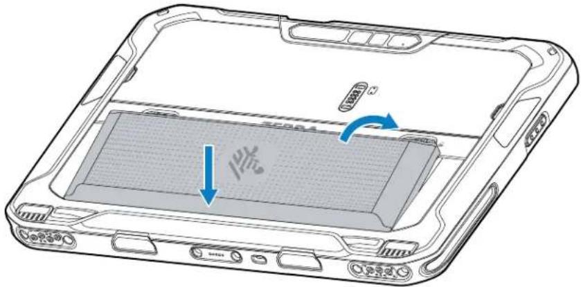
- Press the battery down into the compartment until the release latches snap into place.
Installing the nano SIM Card
This section provides steps to install a nano SIM card.

NOTE: Only use a nano SIM card.

CAUTION: For proper electrostatic discharge (ESD) precautions to avoid damaging the SIM card. Proper ESD precautions include but are not limited to, working on an ESD mat and ensuring that the user is properly grounded.
- Slide the battery release latches toward the sides of the tablet.
The battery ejects slightly.
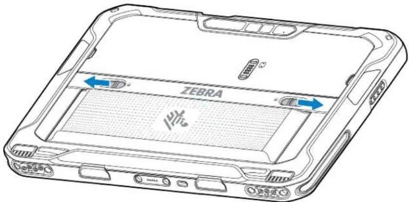
Getting Started
- Lift the battery out of the tablet.

- Remove the access door.
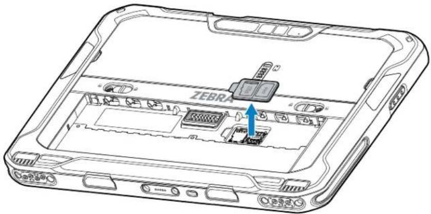
- Slide the SIM card holder to the unlock position.

- Lift the SIM card holder door.
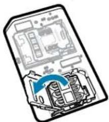
Getting Started
- Place the nano SIM card into the card holder with contacts facing down.
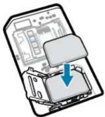
- Close the SIM card holder door.

- Slide to SIM card holder door to the lock position.


NOTE: To ensure proper device sealing, the access door must be replaced and securely seated.
- Replace the access door.

Getting Started
- Insert the battery, bottom first, into the battery compartment at the back of the device.

- Press the battery down into the compartment until the release latches snap into place.
Replacing the Battery
After removing the battery to install a microSD card or SIM card, reinstall the battery to power the tablet.

NOTE: User modification of the device, particularly in the battery well, such as labels, asset tags, engravings, stickers, etc., may compromise the intended performance of the device or accessories. Performance levels such as sealing (Ingress Protection (IP)), impact performance (drop and tumble), functionality, temperature resistance, etc., could be affected. DO NOT put any labels, asset tags, engravings, stickers, etc., in the battery well.

CAUTION: Do not add or remove a microSD card during battery swap.
- Press the Power button until the menu appears.
- Touch Power Off.
- Slide the battery release latches toward the sides of the tablet.
The battery ejects slightly.

Getting Started
- Lift the battery out of the tablet.
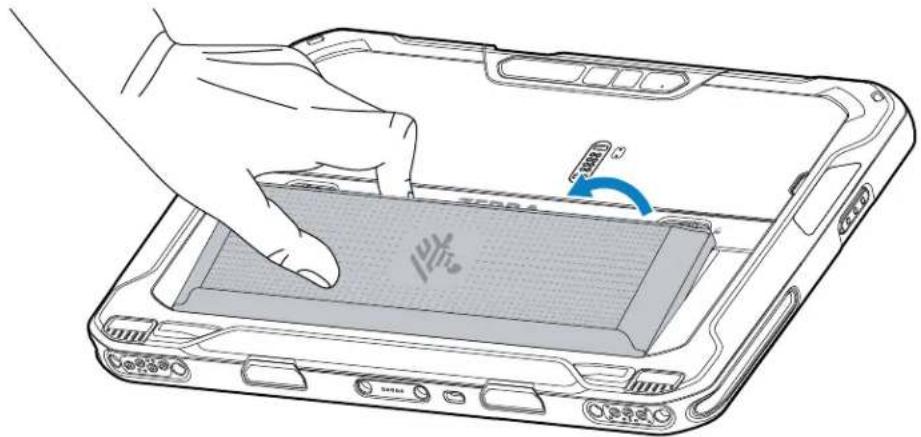
- Insert the replacement battery, bottom first, into the battery compartment at the back of the device.

- Press the battery down into the compartment until the release latches snap into place.
Device Charging
Before using the tablet for the first time, connect it to an external power source to charge the battery.

NOTE: Battery-free tablets do not require charging.
Keep the tablet connected to the external power source until fully charged. The Charging Indicator LED turns green when the tablet is fully charged. You may use the tablet while it is charging.
To charge the main battery, connect the charging accessory to the appropriate power source.
Insert the device into the dock or attach the USB charger. The device turns on and begins charging. The Charging/Notification LED blinks amber while charging, then turns solid green when fully charged.
The battery charges from fully depleted to 90% in approximately 3.5 hours and from fully depleted to 100% in approximately 4.5 hours. In many cases, the 90% charge provides plenty of charge for daily use. A full 100% charge lasts for approximately 14 hours of use. To achieve the best charging results, use only Zebra charging accessories and batteries. Charge batteries at room temperature with the device in sleep mode.
Getting Started
Charging Indicators
Charge the battery before using the device.
Table 3 Charging Indicators
| LED Indication | |
| Off Power is not supplied to the device. The device uses the no cell battery. | |
| Slow blinking orange(1 blink every 4 seconds) | The device is charging. |
| Slow blinking red(1 blink every 4 seconds) | The device is charging, but the battery is at the end of its useful life. |
| Fast blinking orange(2 blinks/second) | Charging error. Possible charging errors include:Temperature is too low or too high.Charging has gone on too long without completion (typically eight hours). |
| Fast blinking red(2 blinks/second) | Charging error and the battery is at the end of its useful life. Possible charging errors include:Temperature is too low or too high.Charging has gone on too long without completion (typically eight hours). |
| Solid Green Charging complete. | |
| Solid Red Charging is complete, but the battery is at the end of useful life. | |
| Blinking red(1 blink/second) | A Battery-free tablet is connected to external power. |
Replacing the microSD Card
When replacing the micoSD card, follow the shutdown instructions to ensure that the data is not corrupted.
To replace the microSD card:
- Press the Power button until the menu appears.
- Touch Power off.
- Touch OK.
- Press the two battery latches in.
- Lift the battery from the device.
- Lift the access door.
- Remove microSD card from the holder.
- Insert the replacement microSD card.
Getting Started

CAUTION: Access door must be replaced and securely seated to ensure proper device sealing.
- Replace the access door.
- Insert the battery, bottom first, into the battery compartment in the back of the device.
- Press the battery down until the battery release latches snap into place.
- Press and hold the Power button to turn on the device.
Replacing the SIM Card
When replacing the SIM card, follow the shutdown instructions to ensure that the data is not corrupted.
To replace the SIM card:
- Press the Power button until the menu appears.
- Touch Power off.
- Touch OK.
- Press the two battery latches in.
- Lift the battery from the device.
- Lift the access door.
- Remove the SIM card from the holder.
- Insert the replacement SIM card.

CAUTION: Access door must be replaced and securely seated to ensure proper device sealing.
- Replace the access door.
- Insert the battery, bottom first, into the battery compartment in the back of the device.
- Press the battery down until the battery release latches snap into place.
- Press and hold the Power button to turn on the device.
Turning off the Display
To turn off the display, press and release the Power button.
Turning off the Device

Turn off the device when no in use for a long period of time.
NOTE: After the device is powered off and external power is applied to the device, the device will automatically power on. This includes a powered Vehicle Dock, and a power supply/USB-C cable.
- Press and hold the Power button until the menu displays.
- Touch Power off.
Using the Device
This section explains how to use your device.
Home Screen
Turn on the device to display the Home screen. Depending on how your system administrator configured your device, your Home screen may appear differently than the graphics in this section.
After the device goes into Sleep mode, the Home screen displays with the lock slider. Touch the screen and slide up to unlock. The Home screen provides four additional screens to place widgets and shortcuts. Swipe the screen left or right to view the additional screens.

NOTE: By default, AOSP devices do not have the same icons on the Home screen as GMS devices. Icons are shown below for example only.
Home screen icons can be configured by the user and may look different than shown.
Figure 4 Home Screen
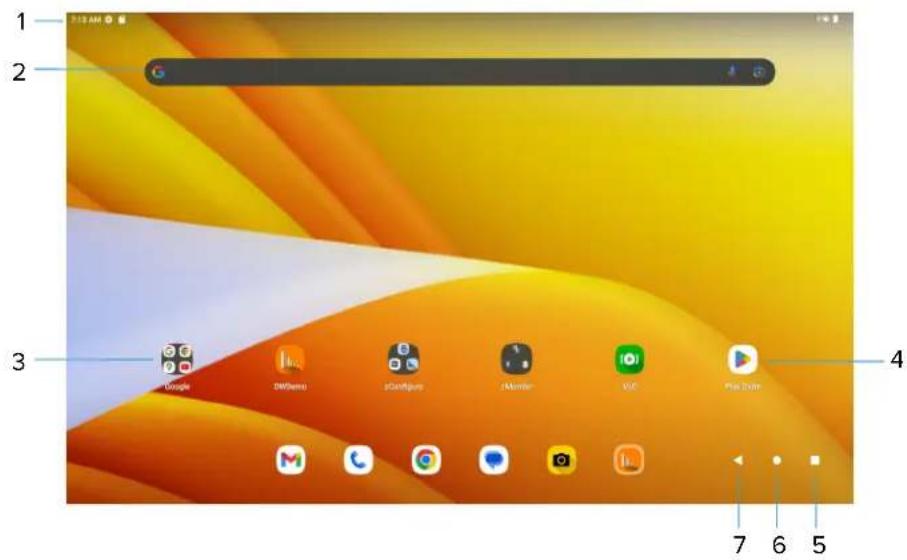
| 1 Status bar Displays the time, status icons (right side), and | |
| notification icons (left side). | |
Using the Device
| 2 Widgets Launches stand-alone apps that run on the home screen. | |
| 3 Folder Contains apps. | |
| 4 Shortcut icons Opens apps installed on the device. | |
| 5 Recent Displays recently used applications. | |
| 6 Home Displays the home screen. | |
| 7 Back Displays the previous screen. | |
Setting the Home Screen Rotation
By default, the Home screen rotation is disabled.
- Touch and hold anywhere on the Home screen until the options appear.
- Touch Home settings.
- Touch the Allow Home screen rotation switch.
- Touch Home.
- Rotate the device.
Status Bar
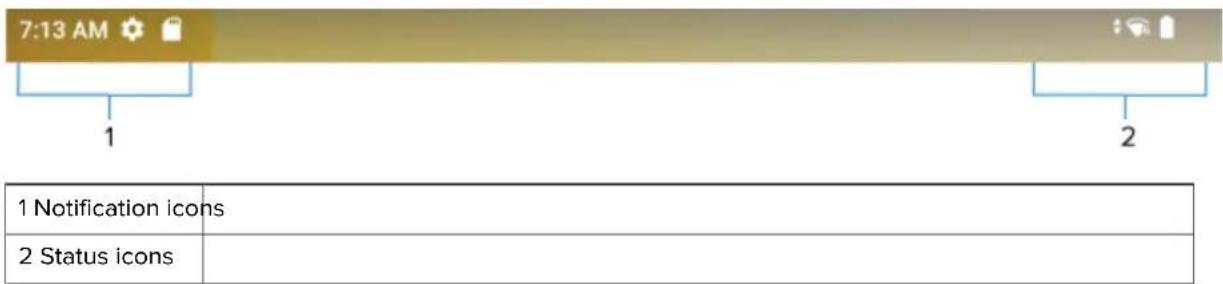
The Status bar displays the time, notification icons (left side), and status icons (right side).
If there are more notifications than can fit in the Status bar, a dot displays indicating that more notifications exist. Swipe down from the Status bar to open the Notification panel and view all notifications and status.
Figure 5 Notifications and Status Icons
Notification Icons
Notification icons indicate app events and messages.
Table 4 Notification Icons
| Icon Description | |
[47X6] | Main battery is low.Backup battery is not ready for Battery True Hot Swap. |
| • | More notifications are available for viewing. |
 | Data is synching. |
 | Indicates an upcoming event. AOSP devices only. |
 | Indicates an upcoming event. GMS devices only. |
 | Open Wi-Fi network is available. |
 | Audio is playing. |
 | Problem with sign-in or sync has occurred. |
 | Device is uploading data. |
 | Animated: the device is downloading data. Static: the download is complete. |
 | Device is connected to or disconnected from a virtual private network (VPN). |
 | Preparing internal storage by checking it for errors. |
 | USB debugging is enabled on the device. |
 | Wired headset with a boom module is connected to the device. |
 | Wired headset without a boom module is connected to the device. |
 | PTT Express Voice client status. |
 | Indicates the RxLogger app is running. |
 | Indicates the Bluetooth scanner is connected to the device. |
 | Indicates the connected scanner is in HID mode. |
Status Icons
Status icons display system information for the device.
Table 5 Status Icons
| Icon Description | |
 | Alarm is active. |
| Main battery is fully charged. | |
| Main battery is partially drained. | |
| Main battery charge is low. | |
| Main battery charge is very low. | |
| Main battery is charging. | |
| UPS battery is fully charged. | |
| All sounds, except media and alarms, are muted. Vibrate mode is active. | |
| Do Not Disturb mode active. | |
| Airplane Mode is active. All radios are turned off. | |
| Bluetooth is on. | |
| Connected to a Bluetooth device. | |
 | Connected to a Wi-Fi network. Indicates the Wi-Fi version number. |
 | Not connected to a Wi-Fi network or no Wi-Fi signal. |
 | Connected to an Ethernet network. |
 | Speakerphone enabled. |
 | Portable Wi-Fi hotspot is active (WWAN only). |
 | Connect to a 6E network (WWAN only).a |
 | Connect to a 5G network (WWAN only).a |
 | Connected to a 4G LTE/LTE-CA network (WWAN only).a |
| [weval] | Connected to a DC-HSPA, HSDPA, HSPA+, HSUPA, LTE/LTE-CA or WCMDMA network (WWAN only).a |
| [weval] | Connected to a WCDMA network (WWAN only).a |
| [weval] | Connected to a DC - HSPA, HSDPA, HSPA+ or HSUPA network (WWAN only).a |
| [weval] | Connected to an EDGE network (WWAN only).a |
| [weval] | Connected to a GPRS network (WWAN only).a |
| [weval] | Roaming from a network (WWAN only). |
| [weval] | No SIM card installed (WWAN only). |
| aCellular network icon that appears is dependent upon the carrier/network. | |
Managing Notifications
Notification icons report the arrival of new messages, calendar events, alarms, and ongoing events. When a notification occurs, an icon appears in the Status bar with a brief description.
Figure 6 Notification Panel

- To view a list of all notifications, open the Notification panel by dragging the Status bar down from the top of the screen.
- To respond to a notification, open the Notification panel and then touch a notification. The Notification panel closes, and the corresponding app opens.
- To manage recent or frequently used notifications, open the Notification panel and then touch Manage notifications. Touch the toggle switch next to an app to turn off all notifications, or touch an app for more notification options.
- To clear all notifications, open the Notification panel and then touch CLEAR ALL. All event-based notifications are removed. Ongoing notifications remain in the list.
• To close the Notification panel, swipe the Notification panel up.
Opening the Quick Access Panel
Use the Quick Access panel to access frequently used settings (for example, Airplane mode).

NOTE: Not all icons are pictured. Icons may vary.
Figure 7 Quick Access Panel

- If the device is locked, swipe down once.
- If the device is unlocked, swipe down once with two fingers, or twice with one finger.
- If the Notification panel is open, swipe down from the Quick Settings bar.
Quick Access Panel Icons
Quick Access panel icons indicate frequently used settings (for example, Airplane mode).
Table 6 Quick Access Panel Icons
| Icon Description | |
 | Display brightness - Use the slider to decrease or increase the brightness of the screen. |
 | Wi-Fi network - Turn Wi-Fi on or off. To open Wi-Fi settings, touch the Wi-Fi network name. |
 | Bluetooth settings - Turn Bluetooth on or off. To open Bluetooth settings, touch Bluetooth. |
 | Battery saver - Turn Battery saver mode on or off. When Battery saver mode is on the performance of the device is reduced to preserve battery power (not applicable). |
 | Invert colors - Invert the display colors. |
 | Do not disturb - Control how and when to receive notifications. |
 | Mobile data - Enables or disables data transfer via the WAN. The device is still available for voice calls and texts. To open Mobile data settings, touch and hold (WWAN only). |
 | Airplane mode - Turn Airplane mode on or off. When Airplane mode is on the device does not connect to Wi-Fi or Bluetooth. |
 | Auto-rotate - Lock the device's orientation in portrait or landscape mode or set to automatically rotate. |
 | Flashlight - Turn the flashlight or camera flash on or off. When the flashlight is activated, it stays on unless it is turned off or the camera app is run. |
 | Location - Enable or disable locationing feature. |
 | Hotspot - Turn on to share the device's mobile data connection with other devices. |
 | Data Saver - Turn on to prevent some apps from sending or receiving data in the background. |
 | Night Light - Tint the screen amber to make it easier to look at the screen in dim light. Set Night Light to turn on automatically from sunset to sunrise, or at other times. |
 | Screen Cast - Share phone content on Chromecast or a television with Chromecast built-in. On the Cast screen, check the "enable wireless display" option, and then touch "cast screen" to display a list of devices. Touch a device in the list to begin casting. |
 | Dark Theme - Toggles dark theme on and off. Dark themes reduce the luminance emitted by the screen, while meeting minimum color contrast ratios. It helps improve visual ergonomics by reducing eye strain, adjusting brightness to current lighting conditions, and facilitating screen use in dark environments, while conserving battery power. |
 | Focus mode - Turn on to pause distracting apps. To open Focus mode settings, touch and hold. |
 | Bedtime mode - Turn grayscale on and off. Grayscale turns the screen black and white, reducing phone distractions and improving battery life. |
 | Nearby Share - Helps find and interact with services and devices close to the device. |
 | Screen Record - Makes a video recording of everything that happens on the screen, with options to include audio and screen touches. |
 | NFC - Enable or disable NFC communication. |
Battery Management
Observe the recommended battery optimization tips for the device.

NOTE: Not applicable for Battery-free tablets.
- Set the screen to turn off after a short period of inactivity.
- Reduce screen brightness.
- Turn off all wireless radios when not in use.
- Turn off automatic syncing for Email, Calendar, Contacts, and other apps.
- Minimize the use of apps that keep the device from sleeping, for example, music and video apps.

NOTE: Before checking the battery charge level, remove the device from any AC power source (cradle or cable).
Battery True Hot Swap
Replacing the Main Battery using the True Hot Swap feature allows the device to maintain Wi-Fi\WAN connectivity and memory persistence while replacing the depleted battery with a fully charged battery. When the battery is removed, the backup super capacitor immediately takes over to maintain the system, including Wi-Fi\WAN connectivity (only voice, data and current state of applications) for a maximum of 30 seconds. During this time, the user is still able to interact with the device, however, some mitigations, such as dimming the display backlight, disabling the scanner, disabling NFC, and lowering the volume are made to conserve power consumption. After this period, the device enters emergency (critical) suspend and maintains the memory (device resumes instead of rebooting) for a maximum of 60 seconds. If the battery is not replaced within 60 seconds, the memory persistence may run out and the device will reboot after installing the charged battery. The persistence duration of 30 seconds for Wi-Fi\WAN and 60 seconds for memory are maximum values. These durations may be reduced depending on the usage of the applications, network considerations, and hardware features being used on the device.
Battery True Hot Swap Persistence
The persistence duration of 30 seconds for Wi-Fi\WAN and 60 seconds for memory are maximum values. Although there is the ability to interact with the device during this time, the device settings will be in the following state during the Battery True Hot Swap and restored after the swap:
• Display dims to 10% brightness
• Volume reduces to level 1
- Reduced uplink/downlink throughput
- Disabled features: NFC, scanner, Soft AP, Wi-Fi direct.
Other Factors Affecting Battery True Hot Swap Behavior
Avoid the following activities before and during a Battery True Hot Swap:
- Any new user-initiated activities on the device during battery removal
• Third party applications or launchers holding a wafelock - Initiating or maintaining a WAN voice call
Using the Device
- Initiating or maintaining a WAN data transfer (files, streaming).
True Hot Swap Battery Replacement
Follow the proper procedures when performing a True Hot Swap.

CAUTION: If the backup super capacitor does not have enough power, an icon displays in the Status bar. When this icon displays, it is not recommended to perform a True Hot Swap. If the battery is removed, the message Backup battery is critically low! Insert battery immediately displays.
To perform a True Hot Swap:
- Press the battery latches in and lift up to remove the battery from the device. A 30 second countdown timer displays.
The backup super capacitor takes over immediately and the device remains powered with the display dimmed.


NOTE: If the battery is not replaced after 30 seconds (max.), the device display turns off and the device enters into memory persistence state for an additional 60 seconds (max.).
- Insert the replacement battery, bottom first, into the battery compartment in the back of the device.

NOTE: If the device does not automatically turn on, press and hold the power button for 6 seconds and the device reboots.
- Press the battery down until the battery release latches snap into place. If the device display turn off, it should automatically turn on.
Battery True Hot Swap Recommendations
to ensure a successful hot swap.

NOTE: User modification of the device, particularly in the battery well, such as labels, asset tags, engravings, stickers, etc., may compromise the intended performance of the device or accessories. Performance levels such as sealing (Ingress Protection (IP)), impact performance (drop and tumble), functionality, temperature resistance, etc., could be affected. DO NOT put any labels, asset tags, engravings, stickers, etc., in the battery well.

CAUTION: Do not add or remove a microSD card during battery replacement.
Ensure the following before performing a True Hot Swap:
- This Backup Power icon (1) indicates that the backup power is not ready. Issues may include: Super Cap is not fully charged, extreme temperature conditions, or successive battery swap implemented.

- Set the Display Backlight Brightness level to 50% .
- Set the Media Volume to 50% while on a voice call.
- If enabled, turn off Time of Flight (TOF) until the True Hot Swap is complete.
- If the Camera application is in use, turn off the application until True Hot Swap is complete.
- If the Video Call is in an active session, turn off the video application (voice may be continued) until True Hot Swap is complete.
Battery-Free Operation
Battery-free ET6x tablets vary from the standard product.
- Battery-free tablets operate only when installed in a Vehicle Dock.
- Battery-free tablets contain a large super capacitor that powers the tablet for a maximum of five minutes when removed from the Vehicle Dock.
- Battery Management app is not loaded on the Battery-free tablets.
- Battery options in Setting is not available.
- The battery icon displays in the Status bar and always indicates 50% .
Interactive Sensor Technology
To take advantage of these sensors, applications use API commands. Refer to the Google Android Sensor APIs for more information. For information on the Zebra Android EMDK, go to: techdocs.zebra.com.
The device contains sensors that monitor movement, orientation, and ambient light.
- Gyroscope - Measures angular rotational velocity to detect rotation of the device.
- Accelerometer - Measures the linear acceleration of movement to detect the orientation of the device.
- Digital Compass - The digital compass or magnetometer provides simple orientation in relation to the Earth's magnetic field. As a result, the device always knows which way is North so it can auto rotate digital maps depending on the physical orientation of the device.
- Light Sensor - Detects ambient light and adjusts the screen brightness.
Waking the Device
The device goes into Sleep mode when you press Power or after a period of inactivity (set in the Display settings window).
- To wake the device from Sleep mode, press Power or the configured wake-up sources.
The Lock screen displays.
Using the Device
- To wake the device from Sleep mode, press Power.
The Lock screen displays.
- To wake the device from Sleep mode, press Scan.
The Lock screen displays.
- Swipe the screen up to unlock.
- If the Pattern screen unlock feature is enabled, the Pattern screen appears instead of the Lock screen.
- If the PIN or Password screen unlock feature is enabled, enter the PIN or password after unlocking the screen.

NOTE: If you enter the PIN, password, or pattern incorrectly five times, you must wait 30 seconds before trying again.
- If you forget the PIN, password, or pattern, contact your system administrator.
USB Communication
Connect the device to a host computer to transfer files between the device and the host computer.
When connecting the device to a host computer, follow the host computer's instructions for connecting and disconnecting USB devices, to avoid damaging or corrupting files.
Transferring Files
Use Transfer files to copy files between the device and the host computer.

NOTE: It is recommended to install a microSD card in the device for storing files due to limited internal storage.
- Connect the device to a host computer using a USB accessory.
- On the device, pull down the Notification panel and touch Charging this device via USB.
By default, No data transfer is selected.
- Touch File Transfer.

NOTE: After changing the setting to File Transfer, and then disconnecting the USB cable, the setting reverts back to No data transfer. If the USB cable is reconnected, select File Transfer again.
- Touch File Transfer.
- On the host computer, open File Explorer.
- Locate the device as a portable device.
- Open the Internal storage folder.
- Open the SD card or the Internal storage folder.
- Copy files to and from the device or delete files as required.
Transferring Photos
Use PTP to copy photos from the device to the host computer.
It is recommended to install a microSD card in the device for storing photos due to limited internal storage.
- Connect the device to a host computer using a USB accessory.
- On the device, pull down the Notification panel and touch Charging this device via USB.
- Touch PTP.
- Touch Transfer photos PTP.
- On the host computer, open a file explorer application.
- Open the Internal storage folder.
- Open the SD card or the Internal storage folder.
- Copy or delete photos as required.
Disconnecting from the Host Computer

CAUTION: Carefully follow the host computer's instructions to disconnect USB devices correctly to avoid losing information.

NOTE: Carefully follow the host computer's instructions to unmount the microSD card and disconnect USB devices correctly to avoid losing information.
- On the host computer, unmount the device.
- Remove the device from the USB accessory.
Applications
The APPS screen displays icons for all installed apps. See Application Deployment for information on installing and uninstalling apps. For information on standard Android apps, go to the Google Play Apps Store.
Installed Applications
Aside from the common Google apps, the Zebra-specific apps that are installed on the device are described in this section.
Table 7 Installed Applications
| Item Description | |
 | Battery Manager - Displays battery information (including charge level, status, health, and wear level) and use to place the device in Battery Swap mode when replacing the battery. Not applicable on Tablets without a battery. |
 | Bluetooth Pairing Utility – Use to pair a Zebra Bluetooth scanner with the device by scanning a barcode. |
 | Camera - Take photos or record videos. |
 | DataWedge - Enables data capture using the imager. |
 | Display Link Desktop - Use to present the device screen onto a connected monitor. |
 | DWDemo - Provides a way to demonstrate the data capture features using the imager. |
 | Heater Control - Use to check the status of the heater and sensors when using the device in cold environments. |
Applications
Table 7 Installed Applications (Continued)
 | License Manager - Use to manage software licenses on the device. |
 | RxLogger - Use to diagnose device and app issues. |
 | Settings - Use to configure the device. |
 | SRV PA Settings - Use to select antenna configuration. |
 | StageNow - Allows the device to stage a device for initial use by initiating the deployment of settings, firmware, and software. |
 | VoD - The Video on Device basic app provides a how-to video for proper device cleaning. For Video on Device licensing information, go to learning.zebra.com. |
 | Wireless Analyzer - A diagnostic intelligent app. Use to diagnose surrounding area and display network stats, such as coverage hole detection or AP in the vicinity. Refer to the Worry Free Wi-Fi Analyzer Administrator Guide for Android. Only available with Mobility DNA Enterprise License. |
 | Zebra Bluetooth Settings - Use to configure Bluetooth logging. |
 | Zebra Data Services - Use to enable or disable Zebra Data Services. Some options are set by the system administrator. |
Accessing Apps
Access all apps installed on the device using the APPS window.
- On the Home screen, swipe up from the bottom of the screen.
- Slide the APPS window up or down to view more app icons.
- Touch an icon to open the app.
Switching Between Recent Apps
Switch between open apps quickly.
To switch between open apps:
Applications
1. Touch Recent.
A window appears on the screen with recently used apps.
- Slide the apps displayed left and right to view all recently used apps.
- Swipe up to remove the app from the list and force close the app.
- Touch an icon to open an app or touch Back to return to the current screen.
Battery Manager
The Battery Manager provides detailed information about the battery.

NOTE: Not applicable for Tablets without no battery.
Opening Battery Manager
• To open the Battery Manager app, swipe up from the bottom of the Home screen, and then touch
Battery Manager Information Tab
The Battery Manager displays detailed information about battery charging, health, and status.
Table 8 Battery Icons
| Battery Icon Description | |
 | Battery charge level is between 85% and 100%. |
 | Battery charge level is between 19% and 84%. |
| [k7y5] | Battery charge level is between 0% and 18%. |
• Level - The current battery charge level as a percentage. Displays -% when the level is unknown.
- Wear - The health of the battery in graphical form. When the wear level exceeds 80%, the bar color changes to red.
Applications
• Health - The health of the battery. If a critical error occurs, ⚠ appears. Touch to view the error description.
- Decommission - The battery is past its useful life and should be replaced. See system administrator.
• Good - The battery is good. - Charge error - An error occurred while charging. See system administrator.
• Over Current - An over-current condition occurred. See system administrator. - Dead - The battery has no charge. Replace the battery.
• Over Voltage - An over-voltage condition occurred. See system administrator. - Below Temperature - The battery temperature is below the operating temperature. See system administrator.
- Failure Detected - A failure has been detected in the battery. See system administrator.
- Unknown - See system administrator.
- Charge Status
- Not charging - The device is not connected to AC power.
- Not charging - The device is not charging.
- Charging-AC - The device is connected to AC power and charging or is fast charging via USB.
- Charging-USB - The device is connected to a host computer with a USB cable and charging.
- Discharging - The battery is discharging.
• Full - The battery is fully charged. -
Unknown - The battery status is unknown.
-
Time until Full - The amount of time until the battery is fully charged.
- Time since charging - The amount of time since the device began charging.
- Time until empty - The amount of time until the battery is empty.
- Advanced info - Touch to view additional battery information.
- Battery present capacity - Maximum amount of charge that could be pulled from the battery under the present discharge conditions if the battery were fully charged.
- Battery level - The battery charge level as a percentage of scale.
- Battery scale - The battery scale level used to determine battery level (100).
- Battery voltage - The current battery voltage in millivolts.
- Scaled Battery Level -
- ZCM Status -
- Battery voltage - The current battery voltage in millivolts.
- Battery temperature - The current battery temperature in degrees Centigrade.
- Battery technology - The type of battery.
- Battery current - The average current into or out of the battery over the last second in mAh.
- Battery manufacture date - The date of manufacture.
Applications
- Battery serial number - The battery serial number. The number matches the serial number printed on the battery label.
- Battery part number - The battery part number.
- Battery decommission status - Indicates if the battery is past its life span.
- Battery Good - The battery is in good health.
- Decommissioned Battery - The battery is past its useful life and should be replaced.
- Base cumulative charge - Cumulative charge using Zebra charging equipment only.
- Battery present capacity - Maximum amount of charge that could be pulled from the battery under the present discharge conditions if the battery were fully charged.
- Battery health percentage - With a range from 0 to 100, this is the ratio of “present_capacity” to “design_capacity” at a discharge rate of “design_capacity”.
- % decommission threshold - The default % decommission threshold for a gifted battery as 80%.
- Battery present charge - Amount of usable charge remaining in the battery at present under the current discharge conditions.
- Battery total cumulative charge - The total accumulated charge in all chargers.
- Battery time since first use - The time passed since the battery was placed in a Zebra terminal for the first time.
- Battery error status - The error status of the battery.
- App version - The application version number.
Camera
This section provides information for taking photos and recording videos using integrated digital cameras.
Taking Photos
Use the front and rear cameras to take photos.
To take a photo:
Applications
- Swipe up from the bottom of the Home screen and touch Camera.

- If necessary, touch the PHOTO.
- To switch between the rear camera and front camera (if available), touch
- Frame the subject on the screen.
- To zoom in or out, press two fingers on the display and pinch or expand your fingers. The zoom controls appear on the screen.
- Touch an area on the screen to focus. The focus square appears.
- Touch
Applications
Recording Videos
Use the front and rear cameras to record videos.
- Swipe up from the bottom of the Home screen and touch Camera.

- If required, touch VIDEO.
- To switch between the rear camera and front camera, touch
- Point the camera and frame the scene.
- To zoom in or out, press two fingers on the display and pinch or expand fingers. The zoom controls appear on the screen.
- Touch to start recording.
The video time remaining appears in the top left of the screen.
- Touch to end the recording.
Camera Settings
In the Camera app, touch
Quick Settings
- Flash - Turn the flash on and off. Options: Auto, On, Off (default).
Applications
- Resolution - Set video resolution to: 4k UHD (rear camera only), FHD 1080p (default), HD 720p, or SD 480 (front camera only).
- Audio - Set to record audio during video recording. Options: Off (default), or On.
- Timer - Select the time after the camera button is pressed. Options: Off (default), 3 sec, or 10 Sec.
-
White balance - Select how the camera adjusts colors in different kinds of light, to achieve the most natural-looking colors:
-
Incandescent - Adjust the white balance for incandescent lighting.
- Fluorescent - Adjust the white balance for fluorescent lighting.
- Auto - Adjust the white balance automatically (default).
- Daylight - Adjust the white balance for daylight.
-
Cloudy - Adjust the white balance for a cloudy environment.
-
HDR mode - High Dynamic Range combines multiple photos at different exposures to produce a good result. Options: Off (default) or On.
- Pro Mode - Enable manual control of camera settings. Manual controls are displayed on the camera screen. Options: Off (default) or On.
Other Settings
- General
- Camera Sounds - Select to play a shutter sound when taking a photo. Options: Disable or Enable (default).
- Location Tags - Includes location information when pictures and videos are taken.
- Storage – Set the location to store the photo to: Phone or SD Card.
- Dirty Lens Detection - Notifies when the camera lens might be dirty. Options: Disable (default) or Enable.
- QR Code Mode - Enable to scan QR Codes with the option to launch URL. Options: Disable (default) or Enable.
- Digital Level - Display a level line to ensure the photo or video is level. Options: Disable (default) or Enable.
- Face Detection - Select to turn face detection Off (default) or On.
- Gestures - View gestures and power user controls.
Applications
- Still Camera
- Photo Grid - Displays a 3 x 3 grid guide to the camera viewport. Options: Disabled (default), or Enable.
- Countdown timer - Select Off (default), 2 seconds, 5 seconds or 10 seconds.
- Selfie Mirror - Select to save a mirror image of the photo. Available for the front camera only. Options: Off (default) or On.
- Picture size - The size (in pixels) of the photo to: 16M pixels (rear camera only, default), 8M pixels (front camera default), 5M pixels, WVGA, VGA, or QVGA.
- Picture quality - Set the picture quality setting to: Low, Standard, or High (default).
- Selfie Flash - Turns the screen white to help produce a little extra light in dimmer settings. Available for the front camera only. Options: Off (default), or On.
- Picture Format - Save still images as JPEG (default), or RAW+JPEG.
- MFNR - Sets multi-frame noise reduction to improve quality in low light conditions. Options: Enabled (default), or Disabled.
- AutoFocus Amination - Set to display a rectangle on the screen when the camera is focusing. Options: Off (default), or On.
- Video Camera
• Video quality - Set video quality to: HD 1080p (default), HD 720p, SD 480p, VGA, CIF, or QVGA.
- Video duration - Set to: 30 seconds (MMS), 10 minutes, 30 minutes (default), or no limit.
- Noise Reduction - Off (default), Fast, or High Quality.
- HEVC Encoder - Save video recordings using high-efficiency video codec (HEVC/h265) for smaller file size. Options: Disabled (default), or Enable.
- Audio Encoder - Set the audio encoder to: AMRNB, or AAC (default).
- Video Rotation - Set the rotation of the video to: 0 (default), 90, 180, or 270.
- Time Lapse - Set the time lapse interval to: Off (default), or a time between 0.5 seconds and 24 hours.
- System
- Restore default - Select to restore all settings to the default values.
- About - Displays the software version of the camera app.
DWDemo
Use DataWedge Demonstration (DWDemo) to demonstrate data capture functionality. To configure DataWedge, refer to techdocs.zebra.com/datawedge/.

NOTE: DataWedge is disabled on the Home screen. To enable DataWedge on the Home screen, go to the DataWedge Launcher profile and enable Barcode input option.
Applications
DWDemo Icons
This table lists the icons available on the DWDemo app.
Table 9 DWDemo Icons
| Category Icon Description | ||
| Illumination Imager |  | ination is on. Touch to turn illumination off. |
| Illumination Imager |  | nation is off. Touch to turn illumination on. |
| Data Capture |  | Indicates a USB scanner is connected to the device. |
| Data Capture |  | Indicates a USB scanner is not connected to the device. |
| Data Capture |  | The data capture function is through the internal imager. |
| Data Capture |  | The data capture function is through the rear camera. |
| Data Capture |  | A Bluetooth scanner is connected. |
| Data Capture |  | A Bluetooth scanner is not connected. |
| Scan Mode Imager |  | licklist mode. Touch to change to normal scan mode. |
| Scan Mode Imager |  | normal scan mode. Touch to change to picklist mode. |
Menu Opens a menu view  | the application information or to set the application DataWedge profile. | |
Selecting a Scanner
DWDemo can scan using various scanning options.
To select a scanner:
1.
Touch

- Select a scan option from the dialog box.
RxLogger
RxLogger is a comprehensive diagnostic tool that provides application and system metrics, and diagnoses device and application issues.
RxLogger logs the following information: CPU load, memory load, memory snapshots, battery consumption, power states, wireless logging, cellular logging, TCP dumps, Bluetooth logging, GPS logging, logcat, FTP push/pull, ANR dumps, etc. All generated logs and files are saved onto flash storage on the device (internal or external).
RxLogger logs the following information: CPU load, memory load, memory snapshots, battery consumption, power states, wireless logging, TCP dumps, Bluetooth logging, logcat, FTP push/pull, ANR dumps, etc. All generated logs and files are saved onto flash storage on the device (internal or external).
RxLogger Configuration
RxLogger is built with an extensible plug-in architecture and comes packaged with a number of plug-ins already built-in. For information on configuring RxLogger, refer to techdocs.zebra.com/rxlogger/.
To open the configuration screen, from the RxLogger home screen touch Settings.
Configuration File
All RxLogger settings are stored in a file on the device, permitting remote configuration and mass deployment of setting files using an enterprise mobile management (EMM) system.
The config.json configuration file is located in the RxLogger\config folder. Copy the file from the device to a host computer using a USB connection. Edit the configuration file and then replace the JSON file on the device. There is no need to stop and restart the RxLogger service because the file change is automatically detected.
The config.json configuration file is located on the microSD card in the RxLogger\config folder. Copy the file from the device to a host computer using a USB connection. Edit the configuration file and then replace the JSON file on the device. There is no need to stop and restart the RxLogger service because the file change is automatically detected.

IMPORTANT: The RxLogger configuration file is human-readable, but it should not be edited by hand as doing so can lead to unpredictable behavior. Zebra recommends modifying RxLogger settings only through the RxLogger UI.
- File name: config.json
- Location:/
/RxLogger - With external SD Card: /storage/sdcard1/RxLogger
- With no external SD Card: /storage/sdcard0/RxLogger When a new settings file is pushed to the device, RxLogger restarts all affected modules and applies the new settings immediately.
Copy the file from the device to a host computer using a USB connection. Edit the configuration file through the RxLogger UI and then replace the JSON file on the device. There is no need to stop and restart the RxLogger service because the file change is automatically detected.
Enabling Logging
- Swipe the screen up and select Rx
Applications
- Touch Start.
Disabling Logging
- Swipe the screen up and select Rx
- Touch Stop.
Extracting Log Files
- Connect the device to a host computer using a USB connection.
- Using a file explorer, navigate to the RxLogger folder.
- Copy the file from the device to the host computer.
- Disconnect the device from the host computer.
Backing Up Data
RxLogger Utility allows the user to make a zip file of the RxLogger folder in the device, which by default contains all the RxLogger logs stored in the device.
• To save the backup data, touch ➤ BackupNow.
RxLogger Utility
RxLogger Utility is a data monitoring application for viewing logs in the device while RxLogger is running. Logs and RxLogger Utility features are accessed using Main Chat Head.
Pass Through Antenna Settings
Use the Pass Through Antenna (PTA) Settings app to select antenna configurations when the tablet is in the Vehicle Dock.
See Installing an External Antenna on page 106 for antenna installation information.
Ensure that the external antenna switch on the back of the Vehicle Dock is set to the EXT ANT position.
Figure 8 External Antenna Switch Position

Signals will only switch to a Vehicle Dock with Pass-Through Antenna when the antenna switch set to EXT ANT.
PTA Settings update continuously and display what signals have been switched to external antenna.
Configuring External Antennas
The Vehicle Dock provides the use of external antennas. Configure the tablet to use these antennas. To select the antenna configuration:
Applications
- Swipe up from the bottom of the display and select PTA Settings.

- Touch Set Antenna For Docked.
The Set Antenna For Decoked dialog displays. The options list three antenna positions which correspond to the antenna connectors on the Vehicle Dock (ANT1, GPS, and ANT2)..
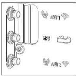
- For ET65, select one of the following:
Set Antenna For Docked
○ WWAN (ANT 1)-GPS-WWAN (ANT 2)
○ WIFI (ANT 1)-GPS-WWAN (ANT 2)
○ WIFI (ANT 1)-NONE-NONE
○ WIFI (ANT 1)-NONE-WIFI (ANT 2)
NONE-NONE-NONE (All Internal)
CANCEL
-
WWAN (ANT 1)-GPS-WWAN (ANT 2)
• WIFI (ANT 1-GPS-WWAN (ANT 2)
• WIFI (ANT 1)-NONE-NONE
• WIFI (ANT 1)-NONE-WIFI (ANT 2)
• NONE-NONE-NONE (All Internal) -
For ET60, select one of the following:
Set Antenna For Docked
○ WIFI (ANT 1)-NONE-NONE
○ WIFI (ANT 1)-NONE-WIFI (ANT 2)
NONE-NONE-NONE (All Internal)
CANCEL
- WWAN (ANT 1)-NONE-NONE
• WIFI (ANT 1-NONE-WWAN (ANT 2)
• NONE-NONE-NONE (All Internal)
Applications
Heater Control
The device heater ensures optimum performance in freezers.

IMPORTANT: The Heater Control app is only applicable to freezer configurations.
The heater benefits include:
- Touch screen heater clears condensation on the display.
- The user interface displays current temperatures.
By default, the app displays temperature in degrees centigrade. To switch to degrees fahrenheit, touch the menu icon and select Show in °F.
Status
The Status tab displays the following:
• Device temperature
- Device humidity
- Heater staus.
Touch Panel Heater

NOTE: Touch Panel Heater tab is available on Freezer configurations only.
Use the Touch Panel Heater tab to enable and set the heater for the touch panel.
- Enable Heater - Turns on or off the Touch panel heater. When on, the switch turns gray.
- Heater on threshold - Set the temperature at which the heater turns on (default - 15°C/59°F).
- Heater off threshold - Set the temperature at which the heater turns off (default - 22°C/71°F).
Settings
This section describes the settings on the device.
Accessing Settings
There are multiple ways to access settings on a device.
- Swipe down with two fingers from the top of the Home screen to open the Quick Access panel and touch ✿
- Double-swipe down from the top of the Home screen to open the Quick Access panel and touch ⚙️
- Swipe up from the bottom of the Home screen to open APPS and touch Settings.
Display Settings
Use Display settings to change the screen brightness, enable night light, change the background image, enable screen rotation, set screen timeout, and change font size.
Setting Screen Brightness
Automatically adjust the screen brightness using the built-in light sensor.
- Go to Settings.
- Touch Display.
- If disabled, touch Adaptive brightness to adjust the brightness automatically. By default, Adaptive brightness is enabled. Toggle the switch to disable.
Setting the Screen Brightness Manually
Manually set the screen brightness using the touchscreen.
- Swipe down with two fingers from the Status bar to open the Quick Access panel.
- . Slide the icon to adjust the screen brightness level.
Settings
Setting Night Light
The Night Light setting tints the screen amber, making the screen easier to look at in low light.
- Go to Settings.
- Touch Display.
- Touch Night Light.
-
Touch Schedule.
-
By default, Night Light is disabled. Touch TURN ON NOW to enable.
-
Select one of the schedule values:
-
None (default)
• Turns on at custom time -
Turns on from sunset to sunrise.
-
Adjust the tint using the Intensity slider.
Setting Lock Screen Notifications
The lock screen display setting wakes the screen when notifications are received.
- Go to Settings.
- Touch Display.
- Touch Lock screen.
- In the When to show section, enable or disable an option using the switch.
Setting Display and Text Size
Set the size of the font in system apps.
- Go to Settings.
- Touch Display > Display size and text.
- In Font size, touch + or - to change the size of the text.
- In Display size, touch + or - to change the size of the display.
Notification LED Brightness Level
Set the brightness level of the notification LED.
- Go to Settings.
- Touch Display > Notification LED brightness Level.
- Use the slider to set the brightness level (default: 15).
Setting Touch Panel Mode
The device display is able to detect touches using a finger, a conductive-tip stylus, or gloved finger.
- Go to Settings.
Settings
- Touch Display.
- Touch Touch panel mode.
-
Select:
-
Finger and Glove to use a finger or a gloved finger on the screen.
- Finger and Wet to use a finger on the screen and when the device may have water on the screen.
- Finger and Passive Stylus to use a finger or a passive stylus on the screen.
Setting the Date and Time
The date and time are automatically synchronized using a NITZ server when the device is connected to a cellular/wireless network. You are only required to set the time zone or set the date and time if the wireless LAN does not support Network Time Protocol (NTP) or when not connected to a cellular/wireless network.
- Go to Settings.
- Touch System > Date & time.
- Touch Use network-provided time to disable automatic date and time synchronization.
- Touch Use network-provided time zone to disable automatic time zone synchronization.
- Touch Date to select the date in the calendar.
- Touch OK.
- Touch Time.
a) Touch the green circle, drag to the current hour, and then release.
b) Touch the green circle, drag to the current minute, and then release.
c) Touch AM or PM.
- Touch Time zone to select the current time zone from the list.
- Touch Update Interval to select an interval to synchronize the system time from the network.
- In TIME FORMAT, choose either Use local default or Use 24-hour format.
General Sound Setting
Press the volume buttons on the device to display on-screen volume controls.
- Go to Settings.
- Touch Sound.
- Touch an option to set sounds.
Sound Options
Press the volume buttons on the device to display on-screen volume controls.
• Media volume - Controls the music, games, and media volume.
- Call volume - Controls the volume during a call. This is replaced by Zebra volume controls on devices with a Mobility DNA Enterprise License.
- Alarm volume - Controls the alarm clock volume.
Settings
- Do Not Disturb - Mutes some or all sounds and vibrations.
- Live caption - Enable the device to detect speech and automatically display captions.
• Media - Enable media playback options. - Vibration & haptics - Enables various vibration and haptic feedback.
- Shortcut to prevent ringing - Select how the shortcut method prevents ringing.
- Default notification sound - Select a sound to play for all system notifications.
- Default alarm sound - Select a sound to play for alarms.
- Screen locking sounds - Play a sound when locking and unlocking the screen (default – enabled).
- Charging sounds and vibration - Play a sound and vibrates when power is applied to the device (default - enabled).
- Touch sounds - Play a sound when making screen selections (default – enabled).
- Always show icon when in vibrate mode - Toggle the display of the vibrate icon when in vibrate mode (default - disabled).
Setting Wake-Up Sources
By default, the device wakes from Sleep mode when the user presses Power. In addition, the device can be configured to wake when the user presses other buttons.
- Go to Settings.
- Touch Wake-Up Sources.
• GUN_TRIGGER
• P1 - Programmable button.
• P2 - Programmable button.
• P3 - Programmable button.
- SCAN - Left scan button.
Remapping a Button
Buttons on the device can be programmed to perform different functions or as shortcuts to installed apps. For a list of key names and descriptions, refer to: techdocs.zebra.com.

NOTE: It is not recommended to remap the scan button.
- Go to Settings.
- Touch Key Programmer. A list of programmable buttons displays.
- Select the button to remap.
- Touch the BUTTON REMAPPING, the SHORTCUT, or the TRIGGER tabs to list the available functions, applications, and triggers.
Settings
- Touch a function or application shortcut to map to the button.

NOTE: If you select an application shortcut, the application icon appears next to the button on the Key Programmer screen.
Remappable Keys
Remap device keys and button to perform various functions.
Figure 9 Key Positions

Table 10 Default Key Programmer Settings
| Item Button Setting Description | |||
| 1 P1 BACK Displays the previous screen. | |||
| 2 P2 HOME Displays the Home screen. | |||
| 3 P3 BUTTON_L2 | |||
| 4 - VOLUME_UP Increase volume. | |||
| 5 + VOLUME_DOWN Decreases volume. | |||
| 6 Scan | BUTTON_R1 Initiates scanning with the internal scanner. | ||
| N/A | GUN_TRIGGER | BUTTON_L1 | Expansion module trigger or button. |
| N/A | BLUETOOTH_REMOTE_TRIGM1_TRIGGER_1 | Remote Bluetooth scan trigger. | |
On-Screen Keyboards
The device provides multiple on-screen keyboard options.
• Android keyboard - AOSP devices only.
• Gboard - GMS devices only.
• Enterprise Keyboard - Only available with Mobility DNA Enterprise License.
Language Usage
Use the Language & input settings to change the device's language, including words added to the dictionary.
Changing the Language Setting
- Go to Settings.
- Touch System > Languages & input.
- Touch Languages. A list of available languages displays.
- If the desired language is not listed, touch Add a language and select a language from the list.
- Touch and hold to the right of the desired language, then drag it to the top of the list.
- The operating system text changes to the selected language.
Adding Words to the Dictionary
The device contains a personal dictionary that allows you to manually add and remove words.
- Go to Settings.
- Touch System > Languages & input > Personal dictionary.
- If prompted, select the language where this word or phase is stored.
- Touch +ADD to add a new word or phrase to the dictionary.
- Enter the word or phrase.
- In the Shortcut text box, enter a shortcut for the word or phrase
- Touch Back.
Notifications
The user can configure notifications for the device and for specific apps. Device notifications settings allow the user to configure how notifications occur on the device. App notification settings allow the user to configure how notifications for a specific app occur.
To view device notification settings, touch Settings > Notifications.
To view app notifications, go to Settings > Notifications > App settings, and then select an app.
Enabling Blink Light
The Notification LED lights blue when an app, such as email and VoIP, generates a programmable notification or to indicate when the device is connected to a Bluetooth device. By default, LED notifications are enabled.
- Go to Settings.
- Touch Notifications.
- Touch Blink light to toggle the notification on or off.
Data Capture
This section provides information for capturing barcode data using various scanning options.
The device supports data capture using:
- SE55 internal imager
- Integrated Camera
• RS5100 Bluetooth Ring Scanner
• RS6100 Bluetooth Ring Scanner
• DS3608 Digital Scanner
• DS3678 Digital Scanner
• DS8178 Digital Scanner
• LI3608 Linear Scanner
• LI3678 Linear Scanner
• DS2278 Digital Scanner
Imaging
The device with an integrated 2D imager has the following features:
- Omnidirectional reading of a variety of barcode symbologies, including the most popular linear, postal, PDF417, Digimarc, and 2D matrix code types.
- The ability to capture and download images to a host for a variety of imaging applications.
- Advanced intuitive laser aiming cross-hair and dot aiming for easy point-and-shoot operation.
The imager uses imaging technology to take a picture of a barcode, stores the resulting image in memory, and executes state-of-the-art software decoding algorithms to extract the barcode data from the image.
Scanning Considerations
Typically, scanning is a simple matter of aim, scan, and decode, with a few quick trial efforts to master it.
However, consider the following to optimize scanning performance:
- Range — Scanners decode optimally over a particular working range — minimum and maximum distances from the barcode. This range varies according to barcode density and scanning device optics. Scan within range for quick and constant decodes; scanning too close or too far away prevents
Data Capture
decodes. Move the scanner closer and further away to find the right working range for the barcodes being scanned.
- Angle — Scanning angle is important for quick decodes. When the illumination/flash reflects directly back into the imager, the specular reflection can blind/saturate the imager. To avoid this, scan the barcode so that the beam does not bounce directly back. Do not scan at too sharp an angle; the scanner needs to collect scattered reflections from the scan to make a successful decode. Practice quickly shows what tolerances to work within.
- Hold the device farther away for larger symbols.
- Move the device closer for symbols with bars that are close together.

NOTE: Scanning procedures depend on the app and device configuration. An app may use different scanning procedures from the one listed above.
Scanning with the Internal Scanner
Use the internal imager to capture barcode data.

NOTE: To read a barcode, a scan-enabled app is required. The device contains the DataWedge app that allows the user to enable the scanner to decode barcode data and display the barcode content.
- Ensure that an app is open on the device and a text field is in focus (text cursor in the text field).
- Point the exit window of the device at a barcode.
- Press and hold the scan button.

The aiming dot with illumination turns on to assist in aiming.
Data Capture
- Ensure the barcode is within the area formed by the aiming pattern. The aiming dot is used for increased visibility in bright lighting conditions.
A beep sounds, by default, to indicate the barcode was decoded successfully.
- The captured data appears in the text field.
Scanning with Camera
Use the camera to capture barcode data.

NOTE: To read a barcode, a scan-enabled app is required. The device contains the DataWedge app that allows the user to enable the scanner to decode barcode data and display the barcode content.
- Ensure that an app is open on the device, and a text field is in focus (text cursor in the text field).
- Point the camera window at a barcode.
- Press and hold the scan button. By default, a preview window appears on the screen.

- Move the device until the barcode is visible on the screen.
- A beep sounds, by default, to indicate the barcode is decoded successfully.
- The captured data appears in the text field.
Scanning with the RS5100 Ring Scanner
Use the RS5100 Ring Scanner to capture barcode data.
Figure 10 RS5100 Ring Scanner
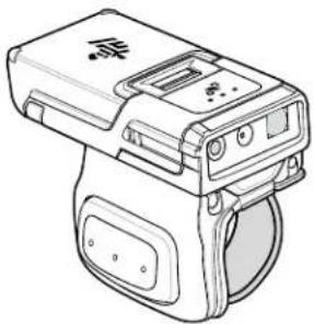
Refer to the RS5100 Ring Scanner Product Reference Guide for more information.

NOTE: To read a barcode, a scan-enabled app is required. The device contains the DataWedge app that allows the user to enable the scanner to decode barcode data and display the barcode content.
To scan with the RS5100:
- Pair the RS5100 with the device.
- Ensure that an app is open on the device and a text field is in focus (text cursor in text field).
- Point the RS5100 at a barcode.

4. Press and hold the trigger.
The red laser aiming pattern turns on to assist in aiming. Ensure the barcode is within the area formed by the cross-hairs in the aiming pattern. The aiming dot increases visibility in bright lighting conditions.
Figure 11 RS5100 Aiming Pattern

When the RS5100 is in Pick List mode, the RS5100 does not decode the barcode until the center of the crosshair touches the barcode.
Figure 12 RS5100 Pick List Mode with Multiple Barcodes in Aiming Pattern
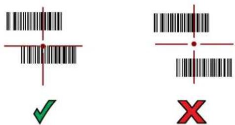
The RS5100 LEDs light green and a beep sounds to indicate the barcode was decoded successfully. The captured data appears in the text field.
Scanning with the RS6100 Bluetooth Ring Scanner
Use the RS6100 Bluetooth Ring Scanner to capture barcode data.
Figure 13 RS6100 Bluetooth Ring Scanner
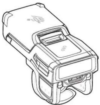
Refer to the RS6100 Bluetooth Ring Scanner Product Reference Guide for more information.

NOTE: To read a barcode, a scan-enabled app is required. The device contains the DataWedge app that allows the user to enable the scanner to decode barcode data and display the barcode content.
To scan with the RS6100:
- Pair the RS6100 with the device.
- Ensure that an app is open on the device and that a text field is in focus (text cursor in text field).
- Point the RS6100 at a barcode.
4. Press and hold the trigger.
The green laser aiming pattern turns on to assist in aiming. Ensure the barcode is within the area formed by the cross-hairs in the aiming pattern. The aiming dot increases visibility in bright lighting conditions.
Figure 14 RS6100 Aiming Pattern

When the RS6100 is in Pick List mode, the RS6100 does not decode the barcode until the center of the crosshair touches the barcode.
Figure 15 RS6000 Pick List Mode with Multiple Barcodes in Aiming Pattern

The RS6100 LEDs light green and a beep sounds to indicate the barcode was decoded successfully. The captured data appears in the text field.
Scanning with the DS3608 USB Scanner
Use the DS3608 Bluetooth Scanner to capture barcode data.
Refer to the DS3608 Product Reference Guide for more information.

NOTE: To read a barcode, a scan-enabled app is required. The device contains the DataWedge app that allows the user to enable the scanner to decode barcode data and display the barcode content.
To scan with the DS3678 scanner:
- Connect the USB scanner to the device.
- Ensure that an app is open on the device and a text field is in focus (text cursor in text field).
- Point the scanner at a barcode.
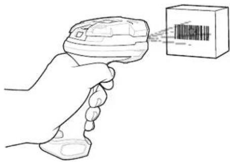
4. Press and hold the trigger.
Ensure the barcode is within the area formed by the aiming pattern. The aiming dot increases visibility in bright lighting conditions.
Figure 18 DS3608 Pick List Mode with Multiple Barcodes in Aiming Pattern

The captured data appears in the text field.
Scanning with the DS3678 Bluetooth Scanner
Use the DS3678 Bluetooth Scanner to capture barcode data.
Refer to the DS3678 Product Reference Guide for more information.

NOTE: To read a barcode, a scan-enabled app is required. The device contains the DataWedge app that allows the user to enable the scanner to decode barcode data and display the barcode content.
To scan with the DS3678 scanner:
- Pair the scanner with the device. See Pairing Bluetooth Scanners for more information.
-
Ensure that an app is open on the device and a text field is in focus (text cursor in text field).
-
Point the scanner at a barcode.

- Press and hold the trigger.
Ensure the barcode is within the area formed by the aiming pattern. The aiming dot increases visibility in bright lighting conditions.
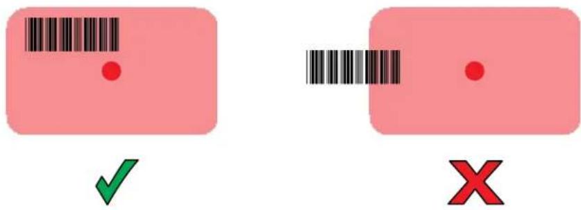
The captured data appears in the text field.
Scanning with the LI3608 Linear Scanner
Use the LI3608 linear imager to capture barcode data.
Figure 20 LI3608 Bluetooth Scanner

Refer to the LI3608 Product Reference Guide for more information.

NOTE: To read a barcode, a scan-enabled app is required. The device contains the DataWedge app that allows the user to enable the scanner to decode barcode data and display the barcode content.
To scan with the LI3608:
- Connect the LI3608 to the device.
- Ensure that an app is open on the device and a text field is in focus (text cursor in text field).
- Point the LI3608 at a barcode.
- Press and hold the trigger.

- Ensure the aiming pattern covers the barcode.

Upon successful decode, the scanner beeps and the LED displays a single green flash.
The captured data appears in the text field.
Scanning with the LI3678 Linear Imager
Use the LI3678 linear imager to capture barcode data.
Figure 21 LI3678 Bluetooth Scanner
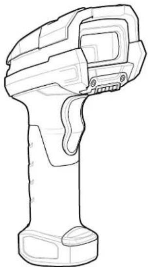
Refer to the LI3678 Product Reference Guide for more information.

NOTE: To read a barcode, a scan-enabled app is required. The device contains the DataWedge app that allows the user to enable the scanner to decode barcode data and display the barcode content.
To scan with the LI3678:
- Pair the LI3678 with the device. See Pairing a Bluetooth Scanner for more information.
- Ensure that an app is open on the device and a text field is in focus (text cursor in text field).
-
Point the LI3678 at a barcode.
-
Press and hold the trigger.

- Ensure the aiming pattern covers the barcode.

Upon successful decode, the scanner beeps and the LED displays a single green flash.
The captured data appears in the text field.
Pairing a Bluetooth Ring Scanner
Before using a Bluetooth Ring Scanner with the device, connect the device to the Ring Scanner.
To connect the Ring Scanner to the device, use one of the following methods:
• Near Field Communication (NFC)
• Simple Serial Interface (SSI)
- Bluetooth Human Interface Device (HID) Mode
Pairing Using Simple Serial Interface (SSI)
Pair the Ring Scanner to the device using Simple Serial Interface.
1.
Swipe up from the bottom of the Home screen and touch .
- Using the Ring Scanner, scan the barcode on the screen.
The Ring Scanner emits a string of high/low/high/low beeps. The Scan LED flashes green indicating that the Ring Scanner is attempting to establish a connection with the device. When a connection is established, the Scan LED turns off and the Ring Scanner emits one string of low/high beeps.
A notification appears on the Notification panel and the icon appears in the Status bar.
Pairing Using Bluetooth Human Interface Device
Pair the Ring Scanner to the device using Human Interface Device (HID).
- Ensure that Bluetooth is enabled on both devices.
- Ensure that the Bluetooth device to discover is in discoverable mode.
- Ensure that the two devices are within 10 meters (32.8 feet) of one another.
- Place the Ring Scanner in HID mode. If the Ring Scanner is already in HID mode, skip to step 5.
a) Remove the battery from the Ring Scanner.
b) Press and hold Restore.
c) Install the battery onto the Ring Scanner.
d) Keep holding the Restore key for about five seconds until a chirp is heard and the Scan LEDs flash green.
e) Scan the barcode below to place the Ring Scanner in HID mode.
Figure 22 Bluetooth HID Barcode

- Remove the battery from the Ring Scanner.
- Re-install the battery into the Ring Scanner.
- Swipe down from the Status bar to open the Quick Access panel and then touch ✿
- Touch Bluetooth.
- Touch Pair new device. The device begins searching for discoverable Bluetooth devices in the area and displays them under Available devices.
- Scroll through the list and select Ring Scanner.
The device connects to the Ring Scanner and Connected appears below the device name.
The Bluetooth device is added to the Paired devices list, and a trusted ("paired") connection is established.
A notification appears on the Notification panel and the A son appears in the Status bar.
Pairing in SSI Mode Using Near Field Communication
The device provides the ability to pair a Ring Scanner in SSI Mode using NFC.
-
Ensure that NFC is enabled on the device.
-
Align the Ring Scanner's NFC icon with the device's NFC icon.
The Status LED blinks blue, indicating that the Ring Scanner is attempting to establish a connection with the device. When a connection is established, the Status LED turns off, and the Ring Scanner emits a single string of low/high beeps.
A notification appears on the device screen.
The Acon appears in the Status bar.
Pairing in HID Mode Using Near Field Communication
The device provides the ability to pair a Ring Scanner in HID Mode using NFC.

NOTE:
Not all Zebra devices support NFC readers and the Tap-to-Pair feature.
- Ensure that NFC is enabled on the device.
- Ensure that Bluetooth is enabled on both devices.
- Ensure that the Bluetooth device to discover is in discoverable mode.
- Ensure that the two devices are within 10 meters (32.8 feet) of one another.
- Place the Ring Scanner in Human Interface Device (HID) mode. If the Ring Scanner is already in HID mode, skip to step 6.
a) Remove the battery from the Ring Scanner.
b) Press and hold the Restore key.
c) Install the battery onto the Ring Scanner.
d) Keep holding the Restore key for about five seconds until a chirp is heard and the Scan LEDs flash green.
e) Scan the barcode below to place the Ring Scanner in HID mode.
Figure 23 Bluetooth HID Barcode

- Remove the battery from the Ring Scanner.
- Re-install the battery into the Ring Scanner.
- Align the Ring Scanner's NFC icon with the device's NFC icon.
The Status LED blinks blue, indicating that the Ring Scanner is attempting to establish a connection with the device. When a connection is established, the Status LED turns off, and the Ring Scanner emits a single string of low/high beeps.
A notification appears on the device screen.
The Acon appears in the Status bar.
Pairing a Bluetooth Scanner
Before using a Bluetooth scanner with the device, connect the device to the Bluetooth scanner.
Connect the scanner to the device using one of the following methods:
- Simple Serial Interface (SSI) mode
- Bluetooth Human Interface Device (HID) mode
Pairing Using Bluetooth Human Interface Device
Pair the Bluetooth scanner to the device using HID.
To pair the scanner with the device using HID:
- Remove the battery from the scanner.
- Replace the battery.
- After the scanner reboots, scan the barcode below to place the scanner in HID mode.

- On the device, swipe down from the Status bar to open the Quick Access panel and then touch ✿
- Touch Bluetooth.
- Touch Pair new device. The device begins searching for discoverable Bluetooth devices in the area and displays them under Available devices.
- Scroll through the list and select XXXXX xxxxxx, where XXXXX is the scanner and xxxxxx is the serial number.
The device connects to the scanner, the scanner beeps once and Connected appears below the device name. The Bluetooth device is added to the Paired devices list and a trusted (“paired”) connection is established.
Pairing Using Simple Serial Interface (SSI)
Pair the Ring Scanner to the device using Simple Serial Interface.
- Swipe up from the bottom of the Home screen and touch .
- Using the Ring Scanner, scan the barcode on the screen.
The Ring Scanner emits a string of high/low/high/low beeps. The Scan LED flashes green indicating that the Ring Scanner is attempting to establish a connection with the device. When a connection is established, the Scan LED turns off and the Ring Scanner emits one string of low/high beeps.
A notification appears on the Notification panel and the icon appears in the Status bar.
Connecting a USB Scanner to a Device
When connecting a USB scanner to a device, connect in either SSI or HID mode.
To connect a USB scanner, use one of the following methods:
- Simple Serial Interface (SSI) mode
• Human Interface Device (HID) mode.
Connecting Using Simple Serial Interface
Connect the USB scanner to the device using SSI mode.
Ensure that the scanner is in SSI mode. Refer to the Refer to the scanner Product Reference Guide and scan the SSI Over USB CDC barcode.
Configure DataWedge scanner selection.
- Connect the scanner cable USB connector to the USB port of the device or the USB port on the Vehicle Dock.
The scanner beeps.
- Open an application and scan a barcode.
The barcode data displays in the text field.
Connecting Using HID Mode
Connect the USB scanner to the device using HID mode.
Ensure that the scanner is in HID mode. Refer to the Refer to the scanner Product Reference Guide and scan the USB HID Keyboard barcode or perform a factory reset.
- Connect the scanner cable USB connector to the USB port of the device or to the Vehicle Dock.
- Open an application and scan a barcode.
The barcode data displays in the text field.
DataWedge
DataWedge is a utility that adds advanced barcode scanning capability to any application without writing code. It runs in the background and handles the interface to built-in barcode scanners. The captured barcode data is converted to keystrokes and sent to the target application as if it was typed on the keypad.
DataWedge allows any app on the device to get data from input sources such as a barcode scanner, MSR, RFID, voice, or serial port and manipulate the data based on options or rules.
Configure DataWedge to:
- Provide data capture services from any app.
- Use a particular scanner, reader, or other peripheral devices.
- Properly format and transmit data to a specific app.
To configure DataWedge, refer to techdocs.zebra.com/datawedge/.
Enabling DataWedge
This procedure provides information on how to enable DataWedge on the device.
- Swipe up from the bottom of the Home screen and touch
- Touch > Settings.
- Touch the DataWedge enabled checkbox.
A blue checkmark appears in the checkbox indicating that DataWedge is enabled.
Disabling DataWedge
This procedure provides information on how to disable DataWedge on the device.
- Swipe up from the bottom of the Home screen and touch
- Touch :
- Touch Settings.
- Touch DataWedge enabled.
Supported Devices
This sections provides the supported decoders for each data capture option.
RS5100 Supported Decoders
Lists the supported decoders for the RS5100 Ring Scanner.
Table 11 RS5100 Supported Decoders
| Decoder Default State Decoder Default State Decoder Default State | ||||||
| Australian Postal | O EAN8 X MSI O | |||||
| Aztec X Grid Matrix O PDF417 X | ||||||
| Canadian Postal | O GS1 DataBar X QR Code X | |||||
| Chinese 2 of 5 O GS1 DataBar | Expanded | X Decoder Signature | O | |||
| Codabar X GS1 DataBar | Limited | O TLC 39 O | ||||
| Code 11 O GS1 Datamatrix | O Trioptic 39 | O | ||||
| Code 128 | X GS1 QR Code | O UK Postal | O | |||
| Code 39 X HAN | XIN O UPCA | X | ||||
| Code 93 | O Interleaved 2 of 5 | O UPCEO | X | |||
| Composite AB | O Japanese Postal | O UPCE1 | O | |||
| Composite C O Korean 3 of 5 O US4state O | ||||||
| Discrete 2 of 5 O MAIL MARK X US4state FICS O | ||||||
| Datamatrix X Matrix 2 of 5 O US Planet O | ||||||
| Dutch Postal O Maxicode X US Postnet O | ||||||
| DotCode O MicroPDF O | ||||||
| EAN13 | X MicroQR | O | ||||
Key: X = Enabled, O = Disabled, - = Not Supported
RS6100 Supported Decoders
Lists the supported decoders for the RS6100 Ring Scanner.
Table 12 RS6100 Supported Decoders
| Decoder Default State Decoder Default State Decoder Default State | |||||
| Australian Postal | O EAN8 | X MSI | O | ||
| Aztec | X Grid Matrix | O PDF417 | X | ||
| Canadian Postal | O GS1 DataBar | X QR Code X | |||
| Chinese 2 of 5 | O GS1 DataBar Expanded | X Decoder Signature | O | ||
| Codabar | X GS1 DataBar Limited | O TLC 39 | O | ||
| Code 11 | O | GS1 Datamatrix | O | Trioptic 39 | O |
| Code 128 | X GS1 QR Code | O UK Postal | O | ||
| Code 39 | X HAN XIN OUPCA | X | |||
| Code 93 | O Interleaved 2 of 5 | O UPCEO | X | ||
| Composite AB O Japanese | Postal | O UPCE1 | O | ||
| Composite C O Korean 3 of 5 O US4state O | |||||
| Discrete 2 of 5 O MAIL MARK X US4state FICS O | |||||
| Datamatrix X Matrix 2 of 5 O US Planet O | |||||
| Dutch Postal O Maxicode X US Postnet O | |||||
| DotCode O MicroPDF O | |||||
| EAN13 | X MicroQR | O | |||
Key: X = Enabled, O = Disabled, - = Not Supported
DS3608 Supported Decoders
Lists the supported decoders for the DS3608 scanner.
Table 13 DS3608 Supported Decoders
| Decoder Default State Decoder Default State Decoder Default State | |||||
| Australian Postal | O EAN8 X MSI O | ||||
| Aztec X Grid Matrix O PDF417 X | |||||
| Canadian Postal | — GS1 DataBar X QR Code X | ||||
| Chinese 2 of 5 O GS1 DataBar | Expanded | X Decoder | Signature | — | |
| Codabar X GS1 DataBar | Limited | O TLC 39 | O | ||
| Code 11 O GS1 Datamatrix O Trioptic 39 | O | ||||
| Code 128 | X GS1 QR Code | O UK Postal | O | ||
| Code 39 X HAN XIN O UPCA | X | ||||
| Code 93 | O Interleaved 2 of 5 | O UPCEO | X | ||
| Composite AB | O Japanese Postal | O UPCE1 | O | ||
| Composite C | O | Korean 3 of 5 | O | US4state | O |
| Discrete 2 of 5 | O | MAIL MARK | X | US4state FICS | O |
| Datamatrix | X | Matrix 2 of 5 | O | US Planet | O |
| Dutch Postal | O Maxicode | X US Postnet | O | ||
| DotCode O MicroPDF | O | ||||
| EAN13 | X MicroQR | O | |||
Key: X = Enabled, O = Disabled, — = Not Supported
DS3678 Supported Decoders
Lists the supported decoders for the DS3678 scanner.
Table 14 DS3678 Supported Decoders
| Decoder Default State Decoder Default State Decoder Default State | ||||
| Australian Postal | O EAN8 X MSI O | |||
| Aztec X Grid Matrix O PDF417 X | ||||
| Canadian Postal | — GS1 DataBar X QR Code X | |||
Table 14 DS3678 Supported Decoders (Continued)
| Decoder Default State Decoder Default State Decoder Default State | |||||
| Chinese 2 of 5 O | GS1 DataBar | Expanded | X Decoder | Signature | — |
| Codabar X GS1 | DataBar | Limited | O TLC 39 | O | |
| Code 11 O GS1 | Datamatrix O Trioptic 39 O | ||||
| Code 128 X GS1 | QRCode O UK Postal O | ||||
| Code 39 X HAN | XIN O UPCA X | ||||
| Code 93 O Interleaved 2 | of 5 | O UPCE0 | X | ||
| Composite AB | O Japanese | Postal | O UPCE1 | O | |
| Composite C | O | Korean 3 of 5 | O | US4state | O |
| Discrete 2 of 5 | O | MAIL MARK | X | US4state FICS | O |
| Datamatrix | X | Matrix 2 of 5 | O | US Planet | O |
| Dutch Postal | O Maxicode | X US Postnet | O | ||
| DotCode O MicroPDF | O | ||||
| EAN13 | X MicroQR O | ||||
Key: X = Enabled, O = Disabled, — = Not Supported
LI3608 Supported Decoders
Lists the supported decoders for the LI3608 scanner.
Table 15 LI3608 Supported Decoders
| Decoder Default State Decoder Default State Decoder Default State | |||||
| Australian Postal | — | EAN8 | X MSI | O | |
| Aztec | — | Grid Matrix | O | PDF417 | — |
| Canadian Postal | — | GS1 DataBar | X QR Code | — | |
| Chinese 2 of 5 O GS1 DataBar | Expanded | X Decoder Signature | — | ||
| Codabar X GS1 DataBar | Limited | O TLC 39 O | |||
| Code 11 O GS1 Datamatrix | — | Trioptic 39 O | |||
| Code 128 X GS1 QRCode | — | UK Postal | — | ||
| Code 39 X HAN XIN O UPCA X | |||||
| Code 93 O Interleaved 2 | of 5 | O UPCE0 | X | ||
| Composite AB — Japanese | Postal | — UPCE1 | O | ||
| Composite C — Korean 3 of 5 O US4state — | |||||
| Discrete 2 of 5 O MAIL MARK — US4state FICS — | |||||
| Datamatrix — Matrix 2 of 5 O US Planet — | |||||
| Dutch Postal — Maxicode | — US Postnet — | ||||
| DotCode | O MicroPDF — | ||||
| EAN13 | X | MicroQR | — | ||
Key: X = Enabled, O = Disabled, — = Not Supported
LI3678 Supported Decoders
Lists the supported decoders for the LI3678 scanner.
Table 16 LI3678 Supported Decoders
| Decoder Default State Decoder Default State Decoder Default State | |||||
| Australian Postal | — EAN8 | X | MSI | O | |
| Aztec | — Grid Matrix O PDF417 | — | |||
| Canadian Postal | — GS1 DataBar | X | QR Code | — | |
| Chinese 2 of 5 | O GS1 DataBar Expanded | X | Decoder Signature | — | |
| Codabar | X | GS1 DataBar Limited | O TLC 39 | O | |
| Code 11 | O | GS1 Datamatrix | — | Trioptic 39 | O |
| Code 128 | X | GS1 QRCode | — | UK Postal | — |
| Code 39 | X | HAN XIN | O | UPCA | X |
| Code 93 O Interleaved 2 | of 5 | O UPCE0 | X | ||
| Composite AB — Japanese | Postal | — UPCE1 | O | ||
| Composite C — Korean 3 of 5 O US4state — | |||||
| Discrete 2 of 5 O MAIL MARK — US4state FICS — | |||||
| Datamatrix — Matrix 2 of 5 O US Planet — | |||||
| Dutch Postal — Maxicode | — US Postnet | — | |||
| Decoder Default State Decoder | Default State Decoder | Default State | State | ||
| DotCode O MicroPDF — | |||||
| EAN13 X MicroQR — | |||||
Key: X = Enabled, O = Disabled, — = Not Supported
Camera Supported Decoders
Lists the supported decoders for the internal camera.
Table 17 Camera Supported Decoders
| Decoder Default State Decoder Default State Decoder Default State | |||||
| Australian Postal | O EAN8 X MSI O | ||||
| Aztec X Grid Matrix O PDF417 X | |||||
| Canadian Postal | O GS1 DataBar X QR Code X | ||||
| Chinese 2 of 5 O GS1 DataBar | Expanded | X Decoder Signature | O | ||
| Codabar X GS1 DataBar | Limited | O TLC 39 O | |||
| Code 11 | O | GS1 Datamatrix | O | Trioptic 39 | O |
| Code 128 | X GS1 QR Code | O UK Postal | O | ||
| Code 39 X HAN XIN O UPCA | X | ||||
| Code 93 | O Interleaved 2 of 5 | O UPCEO | X | ||
| Composite AB | O Japanese Postal | O UPCE1 | O | ||
| Composite C | O | Korean 3 of 5 | O | US4state | O |
| Discrete 2 of 5 | O | MAIL MARK | X | US4state FICS | O |
| Datamatrix | X Matrix 2 of 5 | O US Planet O | |||
| Dutch Postal | O Maxicode | X US Postnet | O | ||
| DotCode | X MicroPDF | O | |||
| EAN13 X MicroQR | O | ||||
Key: X = Enabled, O = Disabled, - = Not Supported
Wireless
This section provides information on the wireless features of the device.
Wireless Wide Area Networks
Use Wireless wide area networks (WWANs) to access data over a cellular network.

NOTE: ET65 only.
This section provides information on:
• Sharing a data connection
• Monitoring data usage
- Changing Cellular Network settings
Sharing the Mobile Data Connection
The Tethering & Portable Hotspot settings allow sharing the mobile data connection with a single computer via USB tethering or Bluetooth tethering.
Share the data connection with up to eight devices at once, by turning it into a portable Wi-Fi hotspot. While the device is sharing its data connection, an icon displays at the top of the screen and a corresponding message appears in the notification list.
Enabling USB Tethering

NOTE: USB tethering is not supported on computers running Mac OS. If the computer is running Windows or a recent version of Linux (such as Ubuntu), follow these instructions without any special preparation. If running a version of Windows that precedes Windows 7, or some other operating system, you may need to prepare the computer to establish a network connection via USB.
- Connect the device to a host computer with a USB cable.
The notification Charging this device via USB appears in the Notifications panel. - Go to Settings.
- Touch Network & Internet.
- Touch Hotspot & tethering.
Wireless
- Touch the USB tethering switch to enable.
The host computer is now sharing the device's data connection.
To stop sharing the data connection, touch the USB tethering switch again or disconnect the USB cable.
Enabling Bluetooth Tethering
Use Bluetooth tethering to share the data connection with a host computer.
Configure the host computer to obtain its network connection using Bluetooth. For more information, see the host computer's documentation.
- Pair the device with the host computer.
- Go to Settings.
- Touch Networking & Internet.
- Touch Hotspot & tethering.
- Touch the Bluetooth tethering switch to enable.
The host computer is now sharing the device's data connection.
To stop sharing the data connection, touch the Bluetooth tethering switch again.
Configuring the Wi-Fi Hotspot
- Go to Settings.
- Touch Networking & Internet.
- Touch Hotspot & tethering.
- Touch Wi-Fi hotspot.
- In the Hotspot name text field, edit the name for the hotspot.
- Touch Security and select a security method from the drop-down list.
• WPA3-Personal
a. Touch Hotspot password.
b. Enter a password.
c. Touch OK.
• WPA2-Personal
a. Touch Hotspot password.
b. Enter a password.
c. Touch OK.
- None - If None is selected in the Security option, a password is not required.
- Touch Advanced.
- In the AP Band drop-down list, select 2.4 GHz Band or 5.0 GHz Band.
- If desired, touch Turn off hotspot automatically to turn off Wi-Fi Hotspot when no devices are connected.
Enabling Wi-Fi Hotspot
After configuring the device as a Wi-Fi Hotspot, turn on Wi-Fi Hot Spot to begin using it.
- Go to Settings.
- Touch Networking & Internet.
- Touch Hotspot & tethering.
- Touch Wi-Fi hotspot.
- Toggle the switch to enable.
After a moment, the device starts broadcasting its Wi-Fi network name (SSID). Connect to it with up to eight computers or other devices. The Hotspot icon appears in the Status bar.
To stop sharing the data connection, touch the toggle switch again.
Data Usage
Data usage refers to the amount of data uploaded or downloaded by the device during a given period. Depending on the wireless plan, you may be charged additional fees when your data usage exceeds your plan's limit.
Data usage settings allow:
- Enable Data Saver.
- Set the data usage warning level.
- Set a data usage limit.
• View or restrict data usage by app.
- Identify mobile hotspots and restrict background downloads that may result in extra charges.
Setting Data Usage Warning
Set a warning alert when the device has used a certain amount of mobile data.
- Go to Settings.
- Touch Network & internet > Mobile network > Data warning & limit.
- If necessary, touch Set data warning to enable it.
- Touch Data warning.
- Enter a number.
To switch between megabytes (MB) and gigabytes (GB), touch the down arrow. - Touch SET.
When the data usage reaches the set level, a notification appears.
Setting Data Limit
- Go to Settings.
- Touch Network & internet > Mobile network > Data warning & limit.
- Touch Set data limit.
Wireless
- Touch OK.
- Touch Data limit.
- Enter a number.
To switch between megabytes (MB) and gigabytes (GB), touch the down arrow.
- Touch Set.
When the limit is reached, data automatically turns off and a notification appears.
Cellular Network Settings
Cellular network settings applies to WWAN devices only.
Data When Roaming
Roaming is disabled by default to prevent the device from transmitting data over other carriers' mobile networks when leaving an area that is covered by the carrier's networks. This is useful for controlling expenses if the service plan does not include data roaming.
Enabling MMS Messages
When mobile data is disabled, this feature allows you to send and receive MMS messages using Wi-Fi. This option only displays when mobile data is disabled.
- Go to Settings.
- Touch Network & Internet > Mobile network > Mobile data.
- Touch MMS messages.
- If desired, touch Mobile data to turn mobile data back on.
You can now send and receive MMS messages using Wi-Fi whenever mobile data is disabled.
Setting Preferred Network Type
Change the network operating mode.
- Go to Settings.
- Touch Network & Internet > Mobile network > Preferred network type.
- In the Preferred network type dialog box, select a mode to set as default.
• Automatic(NLW)
- NR 5G only
- LTE only
• 3G only
Setting Preferred Network
Change the network operating mode.
- Go to Settings.
- Touch Network & Internet > Mobile network > Advanced.
Wireless
- Touch Automatically select network.
- Touch Network.
- In the Available network list, select a carrier network.
Configuring the Access Point Name
To use the data on a network, configure the APN information.

NOTE: Many service provider Access Point Name (APN) data are pre-configured in the device. The APN information for all other service provides must be obtained from the wireless service provider.
- Go to Settings.
- Touch Network & Internet > Mobile network > Advanced.
- Touch Access Point Names.
- Touch an APN name in the list to edit an existing APN or touch + to create a new APN.
- Touch each APN setting and enter the appropriate data obtained from the wireless service provider.
- When finished, touch ➤ Save.
- Touch the radio button next to the APN name to start using it.
Locking the SIM Card
Locking the SIM card requires the user to enter a PIN every time the device is turned on. If the correct PIN is not entered, only emergency calls can be made.
- Go to Settings.
- Touch Security > SIM card lock.
- Touch Lock SIM card.
- Enter the PIN associated with the card.
- Touch OK.
- Reset the device.
Wireless Local Area Network
Wireless local area networks (WLANs) allow the device to communicate wirelessly inside a building. Before using the device on a WLAN, the facility must be set up with the required hardware to run the WLAN (sometimes known as infrastructure). The infrastructure and the device must both be properly configured to enable this communication.

NOTE: To extend the life of the battery, turn off Wi-Fi when not in use.
Refer to the documentation provided with the infrastructure (access points (APs), access ports, switches, Radius servers, etc.) for instructions on how to set up the infrastructure.
Once the infrastructure is set up to enforce the chosen WLAN security scheme, use the Wireless & networks settings configure the device to match the security scheme.
The device supports the following WLAN security options:
Wireless
WPA/WPA2/WPA3 Enterprise (EAP)
The Status bar displays icons that indicate Wi-Fi network availability and Wi-Fi status.
Once the infrastructure is set up to enforce the chosen WLAN security scheme, use the Wireless & networks settings to configure the device to match the security scheme.
The device supports the following WLAN security options:
- None
- Enhanced Open
• Wireless Equivalent Privacy (WEP)
• Wi-Fi Protected Access (WPA)/WPA2 Personal (PSK) - WPA3-Personal
• WPA/WPA2-Enterprise - WPA3-Enterprise
• WPA/WPA2/WPA3 Enterprise (EAP)
• WPA3-Enterprise 192-bit
The Status bar displays icons that indicate Wi-Fi network availability and Wi-Fi status.
Connecting to a Wi-Fi Network
When Wi-Fi is on, select a network from the list.
To connect to a Wi-Fi network:
-
Go to Settings.
-
Touch Network & internet.
-
Touch Internet to open the Wi-Fi screen. The device searches for WLANs in the area and lists them.
-
Scroll through the list and select the desired WLAN network.
-
For open networks, touch profile once or press and hold and then select Connect or for secure networks enter the required password or other credentials then touch Connect. See the system administrator for more information.
The device obtains a network address and other required information from the network using the dynamic host configuration protocol (DHCP) protocol. To configure the device with a fixed internet protocol (IP) address, see Configuring the Device to Use a Static IP Address.
- In the Wi-Fi setting field, Connected appears indicating that the device is connected to the WLAN.
Removing a Wi-Fi Network
Remove a remembered or connected Wi-Fi network.
To remove a network:
- Go to Settings.
- Touch Network & Internet > Wi-Fi.
- Scroll down to the bottom of the list and touch Saved networks.
- Touch the name of the network.
5. Touch FORGET.
WLAN Configuration
This section provides information on configuring Wi-Fi settings.
Configuring a Secure Wi-Fi Network
- Go to Settings.
- Touch Network & Internet > Internet.
- Slide the switch to the ON position.
- The device searches for WLANs in the area and lists them on the screen.
- Scroll through the list and select the desired WLAN network.
- If network security is WPA/WPA2-Personal, WPA3-Personal, or WEP, enter the required password and then touch Connect.
- If network security is WPA/WPA2/WPA3 Enterprise:
a) Touch the EAP method drop-down list and select one of the following:
• PEAP
• TLS
• TTLS
• PWD
• SIM
• AKA
• AKA'
• LEAP
b) Fill in the appropriate information. Options vary depending on the EAP method chosen.
- When selecting CA certificate, Certification Authority (CA) certificates are installed using the Security settings.
- When using the EAP methods PEAP, TLS, or TTLS, specify a domain.
- Touch Advanced options to display additional network options.
Manually Adding a Wi-Fi Network
Manually add a Wi-Fi network if the network does not broadcast its name (SSID) or add a Wi-Fi network when out of range.
- Go to Settings.
- Touch Network & Internet > Internet.
- Slide the Wi-Fi switch to the On position.
- Scroll to the bottom of the list and select Add network.
-
In the Network name text box, enter the name of the Wi-Fi network.
-
In the Security drop-down list, set the type of security to:
-
None
-
Enhanced Open
• WEP
• WPA/WPA2-Personal
• WPA3-Personal
• WPA/WPA2-Enterprise
• WPA3-Enterprise
• WPA3-Enterprise 192-bit -
If the network security is None or Enhanced Open, touch Save.
- If the network security is WEP, WPA3-Personal, or WPA/WPA2-Personal, enter the required password, and then touch Save.
NOTE: By default, the network Proxy is set to None, and the IP settings is set to DHCP. See Configuring for a Proxy Server for setting the connection to a proxy server and see Configuring the Device to Use a Static IP Address for setting the device to use a static IP address.
- If the network security is WPA/WPA2/WPA3 Enterprise:
a) Touch EAP Method drop-down list and select one of the following:
• PEAP
• TLS
• TTLS
• PWD
• SIM
• AKA
• AKA'
• LEAP
b) Fill in the appropriate information. Options vary depending on the EAP methodchoosen.
- When selecting CA certificate, Certification Authority (CA) certificates are installed using the Security settings.
- When using the EAP methods PEAP, TLS, or TTLS, specify a domain.
-
Touch Advanced optionsto display additional network options.
-
If the network security is WPA3-Enterprise 192-bit:
-
Touch CA certificate and select a Certification Authority (CA) certificate. Note: Certificates are installed using the Security settings.
- Touch User certificate and select a user certificate. Note: User certificates are installed using the Security settings.
-
In the Identity text box, enter the username credentials.
-
Touch Save. To connect to the saved network, touch and hold on the saved network and select Connect to network.

Configuring for a Proxy Server
A proxy server is a server that acts as an intermediary for requests from clients seeking resources from other servers. A client connects to the proxy server and requests some service, such as a file, connection, web page, or other resource, available from a different server. The proxy server evaluates the request according to its filtering rules. For example, it may filter traffic by IP address or protocol. If the request is validated by the filter, the proxy provides the resource by connecting to the relevant server and requesting the service on behalf of the client.
It is important for enterprise customers to be able to set up secure computing environments within their companies, making proxy configuration essential. Proxy configuration acts as a security barrier ensuring that the proxy server monitors all traffic between the Internet and the intranet. This is normally an integral part of security enforcement in corporate firewalls within intranets.
- Go to Settings.
- Touch Network & Internet > Internet.
- Slide the Wi-Fi switch to the On position.
- In the network dialog box, select and touch a network.
- If configuring the connected network, touch to edit the network details and then touch the down arrow to hide the keyboard.
- Touch Advanced options.
- Touch Proxy and select Manual.
- In the Proxy hostname text box, enter the address of the proxy server.
- In the Proxy port text box, enter the port number for the proxy server.
- In the Bypass proxy for text box, enter addresses for web sites that are not required to go through the proxy server. Use a comma “,” between addresses. Do not use spaces or carriage returns between addresses.
- If configuring the connected network, touch Save otherwise, touch Connect.
- Touch Connect.
Configuring the Device to Use a Static IP Address
By default, the device is configured to use Dynamic Host Configuration Protocol (DHCP) to assign an Internet protocol (IP) address when connecting to a wireless network.
- Go to Settings.
- Touch Network & Internet > Wi-Fi.
- Slide the Wi-Fi switch to the On position.
- In the network dialog box, select and touch a network.
- If configuring the connected network, touch to edit the network details and then touch the down arrow to hide the keyboard.
- Touch Advanced options.
- Touch IP settings and select Static.
- In the IP address text box, enter an IP address for the device.
- If required, in the Gateway text box, enter a gateway address for the device.
Wireless
- If required, in the Network prefix length text box, enter the prefix length.
- If required, in the DNS 1 text box, enter a Domain Name System (DNS) address.
- If required, in the DNS 2 text box, enter a DNS address.
- If configuring the connected network, touch Save otherwise, touch Connect.
Network Preferences
Use the network preferences to configure advanced Wi-Fi settings. From the Wi-Fi screen, scroll down to the bottom of the screen and touch Network preferences.
- Turn on Wi-Fi automatically - When enabled, Wi-Fi automatically turns back on when near high-quality saved networks.
- Notify for public network - When enabled, notifies the user when an open network is available.
• Additional settings - Touch to view additional Wi-Fi settings. - Install Certificates – Touch to install certificates.
- Wi-Fi Direct - Displays a list of devices available for a direct Wi-Fi connection.
Additional Settings
Use the Additional Settings to configure additional Wi-Fi settings. To view the additional Wi-Fi settings, scroll to the bottom of the Wi-Fi screen and touch Network Preferences > Additional settings.

NOTE: Additional Wi-Fi settings are for the device, not for a specific wireless network.
• Regulatory
- Country Selection - Displays the acquired country code if 802.11d is enabled, else it displays the currently selected country code.
- Region code - Displays the current region code.
• Band and Channel Selection
- Wi-Fi frequency band - Set the frequency band to: Auto (default), 5 GHz only, 2.4 GHz only, 6 GHz only, 2.4 GHz and 5 GHz, 5 GHz and 6 GHz, 2.4 GHz and 6 GHz.
• Available channels (2.4 GHz) - Touch to display the Available channels menu. Select specific channels and touch OK.
• Available channels (5 GHz) - Touch to display the Available channels menu. Select specific channels and touch OK.
• Available channels (6 GHz) - Touch to display the Available channels menu. Select specific channels and touch OK.
- Logging
- Advanced Logging – Touch to enable advanced logging or change the log directory.
- Wireless logs - Use to capture Wi-Fi log files.
- Fusion Logger - Touch to open the Fusion Logger application. This application maintains a history of high level WLAN events which helps to understand the status of connectivity.
- Fusion Status - Touch to display live status of WLAN state. Also provides information about the device and connected profile.
Wireless
- About
- Version - Displays the current version information. Touch the version to display addition version details.
Wi-Fi Direct
Wi-Fi Direct devices can connect to each other without having to go through an access point. Wi-Fi Direct devices establish their own ad-hoc network when required, letting you see which devices are available and choose which one you want to connect to.
- Go to Settings.
- Touch Network & Internet.
- Touch Internet > Network preferences > Wi-Fi Direct.
- Under Peer devices, touch the other device name.
- On the other device, select Accept.
Connected appears on the device. On both devices, in their respective Wi-Fi Direct screes, the other device name displays in the list.
Bluetooth
Bluetooth devices can communicate without wires, using frequency-hopping spread spectrum (FHSS) radio frequency (RF) to transmit and receive data in the 2.4 GHz Industry Scientific and Medical (ISM) band (802.15.1). Bluetooth wireless technology is specifically designed for short-range (10 m (32.8 ft)) communication and low power consumption.
Devices with Bluetooth capabilities can exchange information (for example, files, appointments, and tasks) with other Bluetooth enabled devices such as printers, access points, and other mobile devices.
The device supports Bluetooth Low Energy. Bluetooth Low Energy is targeted at applications in the healthcare, fitness, security, and home entertainment industries. It provides reduced power consumption and cost while maintaining standard Bluetooth range.
Adaptive Frequency Hopping
Adaptive Frequency Hopping (AFH) is a method of avoiding fixed frequency interferers, and can be used with Bluetooth voice. All devices in the piconet (Bluetooth network) must be AFH-capable in order for AFH to work. There is no AFH when connecting and discovering devices. Avoid making Bluetooth connections and discoveries during critical 802.11b communications.
AFH for Bluetooth consists of four main sections:
- Channel Classification - A method of detecting an interference on a channel-by-channel basis, or predefined channel mask.
- Link Management - Coordinates and distributes the AFH information to the rest of the Bluetooth network.
- Hop Sequence Modification - Avoids interference by selectively reducing the number of hopping channels.
- Channel Maintenance - A method for periodically re-evaluating the channels.
When AFH is enabled, the Bluetooth radio “hops around” (instead of through) the 802.11b high-rate channels. AFH coexistence allows enterprise devices to operate in any infrastructure.
The Bluetooth radio in this device operates as a Class 2 device power class. The maximum output power is 2.5 mW and the expected range is 10 m (32.8 ft). A definition of ranges based on power class is difficult to obtain due to power and device differences, and whether in open space or closed office space.
The Bluetooth radio in this device operates as a Class 1 device power class. The maximum output power is 7.5 mW and the expected range is 30 m (98.4 ft). A definition of ranges based on power class is difficult to obtain due to power and device differences, and whether in open space or closed office space.

NOTE: It is not recommended to perform Bluetooth wireless technology inquiry when high rate 802.11b operation is required.
Security
The current Bluetooth specification defines security at the link level. Application-level security is not specified. This allows application developers to define security mechanisms tailored to their specific need. Link-level security occurs between devices, not users, while application-level security can be implemented on a per-user basis. The Bluetooth specification defines security algorithms and procedures required to authenticate devices, and if needed, encrypt the data flowing on the link between the devices. Device authentication is a mandatory feature of Bluetooth while link encryption is optional.
Pairing of Bluetooth devices is accomplished by creating an initialization key used to authenticate the devices and create a link key for them. Entering a common personal identification number (PIN) in the devices being paired generates the initialization key. The PIN is never sent over the air. By default, the Bluetooth stack responds with no key when a key is requested (it is up to user to respond to the key request event). Authentication of Bluetooth devices is based-upon a challenge-response transaction. Bluetooth allows for a PIN or passkey used to create other 128-bit keys used for security and encryption. The encryption key is derived from the link key used to authenticate the pairing devices. Also worthy of note is the limited range and fast frequency hopping of the Bluetooth radios that makes long-distance eavesdropping difficult.
Recommendations are:
- Perform pairing in a secure environment
- Keep PIN codes private and do not store the PIN codes in the device
- Implement application-level security.
Bluetooth Profiles
The device supports the Bluetooth services listed.
Table 18 Bluetooth Profiles
| Profile Description | |
| Service Discovery Protocol (SDP) | Handles the search for known and specific services as well as general services. |
| Serial Port Profile (SPP) Allows use of RFCOMM protocol to emulate serial cable connection between two Bluetooth peer devices. For example, connecting the device to a printer. | |
| Object Push Profile (OPP) Allows the device to push and pull objects to and from a push server. | |
| Advanced Audio Distribution Profile (A2DP) | Allows the device to stream stereo-quality audio to a wireless headset or wireless stereo speakers. |
| Audio/Video Remote Control Profile (AVRCP) | Allows the device to control A/V equipment to which a user has access. It may be used in concert with A2DP. |
| Personal Area Network (PAN) | Allows the use of Bluetooth Network Encapsulation Protocol to provide L3 networking capabilities over a Bluetooth link. Only PANU role is supported. |
| Human Interface Device Profile (HID) | Allows Bluetooth keyboards, pointing devices, gaming devices and remote monitoring devices to connect to the device. |
| Headset Profile (HSP) Allows a hands-free device, such as a Bluetooth headset, to place and receive calls on the device. | |
| Hands-Free Profile (HFP) Allows car hands-free kits to communicate with the device in the car. | |
| Phone Book Access Profile (PBAP) | Allows exchange of Phone Book Objects between a car kit and a mobile device to allow the car kit to display the name of the incoming caller; allow the car kit to download the phone book so you can initiate a call from the car display. |
| Generic Attribute Profile (GATT) | Provides profile discovery and description services for Bluetooth Low Energy protocol. It defines how attributes are grouped together into sets to form services. |
| HID Over GATT Profile (HOGP) | Defines the procedures and features used by Bluetooth low energy HID Devices using GATT and Bluetooth HID Hosts using GATT. |
| Dial Up Networking (DUN) Provides a standard to access the Internet and other dial-up services over Bluetooth. | |
| Generic Access Profile (GAP) | Use for device discovery and authentication. |
| Object EXchange (OBEX) Facilitates the exchange of binary objects between devices. | |
Bluetooth Power States
The Bluetooth radio is off by default.
- Suspend - When the device goes into Sleep mode, the Bluetooth radio stays on.
• Airplane Mode -
- Android A10 OS version and previous versions - When the device is placed in Airplane Mode, the Bluetooth radio turns off. When Airplane mode is disabled, the Bluetooth radio returns to the prior state. When in Airplane Mode, the Bluetooth radio can be turned back on if desired.
- Android A11 OS version and versions onward - When the device is placed in Airplane Mode, the Bluetooth radio is not turned off when the device is connected to a Bluetooth headset or hearing device.
- Airplane Mode - When the device is placed in Airplane Mode, the Bluetooth radio is not turned off when the device is connected to a Bluetooth headset or hearing device.
Enabling Bluetooth
- Swipe down from the Status bar to open the Notification panel.
- Touch to turn Bluetooth on.
Disabling Bluetooth
- Swipe down from the Status bar to open the Notification panel.
- Touch ✗ to turn Bluetooth off.
Discovering Bluetooth Device(s)
The device can receive information from discovered devices without pairing. However, once paired, the device and a paired device exchange information automatically when the Bluetooth radio is on.
- Ensure that Bluetooth is enabled on both devices.
- Ensure that the Bluetooth device to discover is in discoverable mode.
- Ensure that the two devices are within 10 meters (32.8 feet) of one another.
- Swipe down from the Status bar to open the Quick Access panel.
- Touch and hold Bluetooth.
- Touch Pair new device. The device begins searching for discoverable Bluetooth devices in the area and displays them under Available devices.
- Scroll through the list and select a device. The Bluetooth pairing request dialog box appears.
- Touch Pair on both devices.
- The Bluetooth device is added to the Paired devices list and a trusted ("paired") connection is established.
Changing the Bluetooth Name
By default, the device has a generic Bluetooth name that is visible to other devices when connected.
- Go to Settings.
- Touch Connected devices > Connection preferences > Bluetooth.
- If Bluetooth is not on, move the switch to turn Bluetooth on.
- Touch Device name.
- Enter a name and touch RENAME.
Connecting to a Bluetooth Device
Once paired, connect to a Bluetooth device.
- Go to Settings.
- Touch Connected devices > Connection preferences > Bluetooth.
- In the list, touch the unconnected Bluetooth device.
When connected, Connected appears below the device name.
Selecting Profiles on the Bluetooth Device
Some Bluetooth devices have multiple profiles.
- Go to Settings.
- Touch Connected devices > Connection preferences > Bluetooth.
- In the Paired Devices list, touch ⚙ next to the device name.
- Turn on or off a profile to allow the device to use that profile.
Unpairing a Bluetooth Device
Unpairing a Bluetooth device erases all pairing information.
- Go to Settings.
- Touch Connected devices > Connection preferences > Bluetooth.
- In the Paired Devices list, touch ⚙ next to the device name.
- Touch FORGET.
Cast
Use Cast to mirror the device screen on a Miracast enabled wireless display.
- Go to Settings.
- Touch Connected devices > Connection preferences > Cast.
- Touch ▶ Enable wireless display.
The device searches for nearby Miracast devices and lists them. - Touch a device to begin casting.
Near Field Communications
NFC/HF RFID is a short-range wireless connectivity technology standard that enables a secure transaction between a reader and a contactless smart card.
The technology is based on ISO/IEC 14443 type A and B (proximity) ISO/IEC 15693 (vicinity) standards, using the HF 13.56 MHz unlicensed band.
The device supports the following operating modes:
- Reader mode
• Peer-to-Peer Communication - Card Emulation mode.
Using NFC, the device can:
- Read contactless cards, such as contactless tickets, ID cards, and ePassport.
- Read and write information to contactless cards, such as SmartPosters and tickets, as well as devices with an NFC interface, such as vending machines.
- Read information from supported medical sensors.
Wireless
- Pair with supported Bluetooth devices such as printers, ring scanners (for example, RS6000), and headsets (for example, HS3100).
• Exchange data with another NFC device. - Emulate a contactless card such as a ticket.
The device's NFC antenna is positioned to read NFC cards from the top of the device while the device is being held.
Reading NFC Cards
Read contactless cards using NFC.
- Launch an NFC enabled application.
- Hold device as shown.
- Align the card with the NFC antenna on the back of the device.

- Hold the card steadily until the transaction is complete (usually indicated by the application).
Enterprise NFC Settings
Improve NFC performance or increase battery life by selecting which NFC features to use on the device.
- Card Detection Mode - Select a card detection mode.
- Low - Increases battery life by lowering the NFC detection speed.
- Hybrid - Provides a balance between NFC detection speed and battery life (default).
- Standard - Provides the optimal NFC detection speed, but reduces battery life.
- Supported Card Technology - Select an option to detect only one NFC tag type, increasing battery life, but reducing detection speed.
• ISO 14443 Type A
• ISO 14443 Type B
• FeliCa
• ISO 15693
Wireless
- NFC Debug Logging - Use to enable or disable debug logging for NFC.
- Other NFC settings available with Zebra administrator tools (CSP) - Allows configuration of additional Enterprise NFC Settings through staging tools and Mobile Device Management (MDM) solutions with an MX version that supports the Enterprise NFC Settings Configuration Service Provider (CSP). For more information on using the Enterprise NFC Settings CSP, refer to: techdocs.zebra.com.
Vehicle Dock Installation
This section describes different ways to install the Vehicle Dock.
The device can be installed in a variety of ways:
- Position the device horizontally on a desk or mounted on a vehicle console.
- Wall mount the device using the optional wall mount.
• Overhead mount on a lift truck cage using mounting hardware.
Depending on the vibration resistance and pivoting demands, mounting brackets, clamp feet, or RAM mount elements can also be used to attach the device. Contact your Zebra sales office to learn more about the available installation options.

WARNING: The unit could fall during transit or installation/mounting and cause injury. Always ensure that there are two people available when installing or removing the device.
Mounting Safety
Failure to install the Vehicle Dock correctly, or modifications to the Vehicle Dock, may result in serious injury or damage to property.

CAUTION:
Do not install the Vehicle Dock in a location that affects vehicle safety, visibility, or ability to drive.
If mounted above head height, it is recommended to also use a safety strap with the mount bracket.
When using the Vehicle Dock in wet locations, the user must prevent water and dust from settling on the pogo pin connectors. The tablet should always be in dock or cover dock with a plastic bag.
Tighten peripherals with thumbscrews by hand only. Do not use tools for tightening thumbscrews.

IMPORTANT: The vehicle front end connected fuse must meet UL 275. If using an external antenna, connect antenna in a vertical position to the device.

NOTE: If installing peripherals, allow enough space when selecting a mounting location.
To ensure operator safety, you must use a calibrated torque wrench and the supplied mounting hardware specific to the device model purchased when fastening the Vehicle Dock and mount. Use of a mount in vehicles driven on public roads or highways is prohibited. Contact Zebra Technical Support or your Zebra
representative if you have a problem with mount installation. For detailed mounting information, refer to the ET6x Product Reference Guide at zebra.com/support.
Electrical Guidelines
There are various electrical potentials when installing the Vehicle Dock on a vehicle such as a forklift.

WARNING:
Most electrically driven forklift vehicles have floating chassis connected to neither DC+ or DC-. However, electrical faults can cause the battery + or - to be connected to the chassis via low resistance paths. All connected peripherals must be completely isolated.
The Vehicle Dock accepts DC power sources with a minimum of 12 to 15 VDC nominal. A DC/DC Power Supply is required for voltages above 15 VDC nominal.
Applying a voltage above 15 VDC nominal without the DC/DC Power Supply or reversing polarity may result in permanent damage to the dock and tablet and voids the product warranty.

CAUTION: Attach the Vehicle Dock connecting cable as close to the battery as possible. Connecting the Vehicle Dock to large electrical loads, such as converters for the forklift motor may result in random restarts, malfunctions and/or irreparable damage to the Vehicle Dock and tablet.
To connect devices fed by other power sources to the device, such as printers, power up the peripheral devices at the same time or after the device to avoid start-up problems, malfunctions, or irreparable damage to the Vehicle Dock and tablet.
Wiring Guidelines
As with other vehicle cables, carefully consider the routing of the cables to ensure they do not pose a hazard to the operator or the safe operation of the vehicle. If necessary, secure the cables with cable ties or some other mechanical means to prevent loops or loose lengths of wire from catching on stationary items when the vehicle is in motion.
Before installing the cables between the Vehicle Dock and other devices, consider the following:
- Ensure that drilling holes do not damage the vehicle or its wiring.
- Protect cable runs from pinching, overheating and physical damage.
- Use grommets to protect cables that pass through metal.
- Use plastic straps and tie-downs to secure cables and connectors in their desired location, away from areas where they may get snagged or pulled.
- Keep cables away from heat sources, grease, battery acid and other potential hazards.
- Keep cables away from control pedals and other moving parts that may damage the cables or interfere with the operation of the vehicle.

CAUTION: Make sure the cables run inside the roll cage of the vehicle.
Mounting the Vehicle Dock
Mount the Vehicle Dock on various types of vehicle using 3rd party mounting hardware.

NOTE: The Vehicle Dock contains screw hole patterns for 75 mm VESA and 100 mm VESA mounts.
To mount the Vehicle Dock:
- Open the access door.
- Align the mounting screw holes with the screw holes on the third-party mounting hardware.
- Insert four bolts (supplied) into the appropriate screw holes.

- Insert the washers onto the bolts.
- Secure using the four lock washers.
Installing the Keyboard Mounting Bracket
Use the optional Keyboard Mounting Bracket to mount a keyboard onto the Vehicle Dock.
Vehicle Dock Installation

| 1 Mounting holes | |
| 2 Locking knobs | |
| 3 Tray |

NOTE: Mount the Vehicle Dock to third-party mounting systems that use 100 mm or 75 mm VESA mounting patterns.
Vehicle Dock Installation
- Align the Vehicle Dock mounting holes with the keyboard bracket (4) third-party bracket (5) mounting holes.
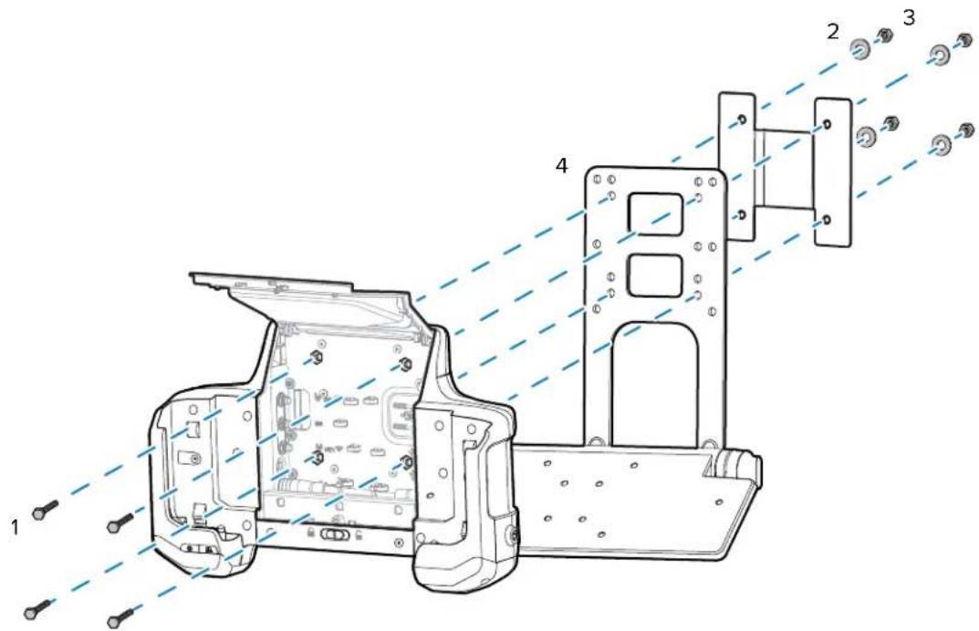
- Insert four bolts (1) into the Vehicle Dock bolt holes and through the brackets (4).
- Place the washers (2) onto the bolts.
- Secure with four lock nuts (3).
Routing Cables
All cable connections must go through the bottom cable access holes.
To route cables:
-
Feed cable up into the bottom of the Vehicle Dock. Cables that connect to the connectors on the left side should be fed up the right cable access hole. Cables that connect to the connectors on the right side should be fed up the left cable access.
-
Connect the cable connector to the Vehicle Dock connector.
- For coax cables, tighten the connector.
- Torque to XXX.
- Use zip ties to secure the cable to the cable mounting tab.
- Close the access door.
Power
Refer to the ET6x Product Reference Guide at zebra.com/support for a complete list of optional parts and accessories.
The installation instructions are divided into:
- CLA Cable installation
- New wired installations
- Replacement legacy installations.
Installing a CLA Cable
Use the CLA cable to power the Vehicle Dock from a vehicle cigarette lighter port.
- Open the Vehicle Dock Access Door.
- Plug the DC connector into the Power port.
- Secure the cable to a mounting point with a cable tie.
- Close the Access Door.
-
Plug the plug into the cigarette lighter receptacle.
-
Route the CLA cable DC connector through the bottom access hole in the bottom of the dock.
New Wired Installations
This section describes the procedures to install the Vehicle Dock in a new installation.
Vehicles with Power 15 VDC or Less
For vehicles with a power source that is 15 VDC or less, a DC/DC Power Supply is not required. Use the Direct Wire Kit to connect the Vehicle Dock to the power source.
![graph LR A["Vehicle Dock"] --> B["300039"] B --> C["Fuse"] C --> D["+ Vehicle Power Source"]](/content/2026/05/958646/images/811a00c7ff413696e192014c3afc6b208195c9b2a3efb984a9ad6f97635c21e5.jpg)
- Measure the distance from the vehicle power source to the Vehicle Dock power port.
- Cut the Direct Wire Kit cable from the DC power plug to length.
- Strip the ends of the two wires to 6 mm (0.25 in.).
- Strip both ends of the fuse holder wires to 6 mm (0.25 in.).
- Using a butt splice connector, connect the red wire to one end of the fuse holder wire.
- Connect a ring terminal to the other end of the fuse holder wire.
- Connect a ring terminal to the end of the black wire.
- Insert the fuse into the fuse holder.
- Close the fuse holder cover.
Vehicle Dock Installation
- Connect the black wire to the negative power source.
- Connect the fuse wire to the positive power source.
- Open the Vehicle Dock Access Door.
- Plug the DC connector into the Power port.
- Secure the cable to a mounting point with a cable tie.
-
Close the Access Door.
-
Route the power connector through the bottom access hole in the bottom of the dock.
Vehicles with Power Greater than 15 VDC
Use a DC/DC Power Supply when the power source (usually the forklift truck battery) exceeds the input range of the ET6x (for example, trucks equipped with a 72 VDC battery).
- Vehicle with power between 19 - 90 VDC and ET60 with heated touch screen, use CBL-ET6-ADP2-1, CA1210, and DC/DC Power Supply (p/n PS1370).
- Vehicle with power between 9 - 60 VDC, use Direct Wire Kit and DC/DC Power Supply (p/n 450083).
- Vehicle with power between 50 - 150 VDC, use Direct Wire Kit and DC/DC Power Supply (p/n 450084).
Mounting the DC/DC Power Supply
Mount the DC/DC Power Supply to the vehicle using screws (not included).

CAUTION:
Only qualified service personnel should connect the device to the vehicle battery.
For proper and safe installation, the input power cable must be connected to a fused circuit on the vehicle. This fused circuit requires a user supplied 5 or 10 amp maximum time delay (slow blow) high interrupting rating fuse. If the supply connection is made directly to the battery, the fuse should be installed in the positive lead within 127 mm (5 in.) of the battery positive (+) terminal.
Avoid usage in areas where moisture can affect the power supply connections. The power supply should be mounted in a dry location within the vehicle or placed in a suitable protective enclosure.
Risk of ignition or explosion. Explosive gas mixture may be vented from the battery. Work only in well ventilated area. Avoid creating arcs and sparks at the battery terminal.

NOTE:
Power adapter and extension cable requirements may vary.
Use the DC/DC Power Supply when replacing an existing vehicle computer installation and for new installations.
Figure 24 450083/84

Figure 25 PS1370

New Installation with PS1370 Power Supply
When installing a new installation, use the DC Power Adapter (p/n CBL-ET6-ADPA2-1), DC/DC Power Supply (p/n PS1370), and the Power Extension Cable (p/n CA1210). Must be used with the ET60 with installed Touch Screen Heater.
![graph LR A["Vehicle Dock"] --> B["PS1370"] B --> C["CA1210"] C --> D["Vehicle Power Source"] A -.->|CBL-ET6-ADP2-1| B](/content/2026/05/958646/images/3360a10a52f0e313dd467ab6b2eebb1a20e5f243af9e538b97043fc72ba7da26.jpg)
- Mount the DC/DC Power Supply to the vehicle using four screws (not included).
- Install the Power Extension Cable to the vehicle power source. Refer to the CA1210 Power Extension Cable Installation Instructions, MN-002747-01, supplied with the cable.
- Connect Power Supply input connector to the Power Extension Cable connector.
- Connect Power Supply output connector to the DC Power Adapter connector.
- Route the DC Power Adapter DC connector through the bottom access hole in the bottom of the dock.
- Plug the DC connector into the Power port.
- Secure the cable to a mounting point with a cable tie.
- Close the Access Door.
New Installation with 450083 or 450084 Power Supply
When installing a new installation, use the Direct Wire Kit (p/n 300039).
![graph LR A["Vehicle Dock"] --> B["450083/4"] B --> C["Fuse"] C --> D["+ Vehicle Power Source"] B -->|300039| A](/content/2026/05/958646/images/3a8ab1ad5d270c5c137d87834b3773d5908611182927f343f7f250679ee26717.jpg)
- Mount the DC/DC Power Supply (p/n 450083 or 450084) to the vehicle using four screws (not included).
- Using a #2 Phillips screwdriver, remove and retain the four screws securing the cover to the power supply.
| Option Description | |
| 1 Screw (4) | |
- Lift the cover off the power supply.
| Option Description | |
| 1 Input power | terminal |
| 2 Mounting point | |
| 3 Output power | terminal |
- Measure the distance from the installed DC/DC Power Supply to the Vehicle Dock power port.
- Cut the Direct Wire Kit cable from the DC power plug to length. Save the rest of the cable.
- Strip the ends of the two wires to 6 mm (0.25 in.).
- Insert the black wire into the Vo-terminal and the red wire into the Vo+ terminal.
- Secure the terminal screws.
- Use cable tie (not included) to secure the cable to the mounting point.
- Strip the ends of the two wires to 6 mm (0.25 in.).
- Insert the black wire into the Vin- terminal and the red wire into the Vin+ terminal.
- Secure the terminal screws.
- Strip the end of the Ground wire (customer supplied) to 6 mm (0.25 in.).
- Insert the ground wire into the GND terminal.
- Use cable tie (not included) to secure the cables to the mounting point.
- Strip both ends of the fuse holder wires to 6 mm (0.25 in.).
- Using a butt splice connector, connect the red wire to one end of the fuse holder wire.
- Connect a ring terminal to the other end of the fuse holder wire.
- Connect a ring terminal to the end of the black wire.
- Insert the fuse into the fuse holder.
-
Close the fuse holder cover.
-
Connect the black wire to the to the negative connection of the vehicle DC power source.
- Connect red wire to the positive connection of the vehicle DC power source.
- Secure the ground wire to the DC/DC Power Supply mounting screw.
- Place the cover on the DC/DC Power Supply.
- Secure using the four screws retained during removal.
- Route the DC Power Adapter DC connector through the bottom access hole in the bottom of the dock.
- Plug the DC connector into the Power port.
- Secure the cable to a mounting point with a cable tie.
- Close the Access Door.
Replacing Legacy Installations
This section describes the procedures to install the Vehicle Dock in an existing installation.
Replacing an Existing Legacy Installation with PS1370 Power Supply
When replacing an existing legacy installation with an ET6x installation, use the DC Power Adapter (p/n CBL-ET6-ADPA2-1), and the DC/DC Power Supply (p/n PS1370).
![graph LR A["Vehicle Dock"] --> B["PS1370"] B --> C["Vehicle Power Source"] D["CBL-ET6-ADP2-1"] --> B E["Existing Cable"] --> C](/content/2026/05/958646/images/1fc4b4a053369d3efb9757c114120c5ecb3cfab4a9df7fe06bef92ed249111f4.jpg)
- Mount the DC/DC Power Supply to the vehicle using four screws (not included).
- Connect Power Supply input connector to the existing power cable connector.
- Connect Power Supply output connector to the DC Power Adapter connector.
- Open the Vehicle Dock Access Door.
- Route the DC Power Adapter DC connector through the bottom access hole in the bottom of the dock.
- Plug the DC connector into the Power port.
- Secure the cable to a mounting point with a cable tie.
- Close the Access Door.
Replacing an Existing Legacy Installation with 450083 or 450084 Power Supply
When replacing an existing legacy installation with an ET6x installation, use the Direct Wire Kit and either a DC Power Adapter Cable (p/n CBL-ET-ADA1-1 for Zebra vehicle computers), or DC Power Adapter Cable (p/n ACC-PWRCBL01 for Honeywell or LXE vehicle computers).
![graph LR A["Vehicle Dock"] --> B["300039"] B --> C["450083/4"] C --> D["AC-ACC-PWRCBL01"] D --> E["Vehicle Power Source"] F["Existing Cable"] --> D](/content/2026/05/958646/images/bc60fd5a4c62502cc47f759cbf67b48dfa46d5e4d2d7f6a446374dad2f345a6c.jpg)
Vehicle Dock Installation
- Remove the existing vehicle computer.
- Install the appropriate DC/DC Power Supply.
- Measure the distance from the installed DC/DC Power Supply to the Vehicle Dock power port.
- Cut the Direct Wire Kit cable from the DC power plug to length.
- Strip the ends of the two wires to 6 mm (0.25 in.).
- Insert the black wire into the Vo-terminal and the red wire into the Vo+ terminal.
- Secure the terminal screws.
- Use cable tie (not included) to secure the cable to the mounting point.
- Secure the terminal screw.
- Strip the ends of CBL-ET-ADPA1-1 cable (or ACC-PWRCBL01 for Honeywell and LXE) to 6 mm (0.25 in.).
- Insert the cable black wire into the Vin- terminal and the red wire into the Vin+ terminal.
- Strip the ends of a ground wire (sold separately) to 6 mm (0.25 in.).
- Insert one end of the ground wire (customer supplied) into the GND terminal.
- Secure the terminal screws.
- Use cable tie (not included) to secure the cables to the mounting point.
- Connect cable connector to the existing power cable connector.
- Secure the ground wire to the DC/DC Power Supply mounting screw.
- Place the cover on the DC/DC Power Supply.
- Secure using the four screws retained during removal.
- Open the Vehicle Dock Access Door.
- Route the Direct Wire Cable DC connector through the bottom access hole in the bottom of the dock.
- Plug the DC connector into the Power port.
- Secure the cable to a mounting point with a cable tie.
- Close the Access Door.
Installing an External Antenna
To determine the best antenna option for your location, contact your Zebra representative.


CAUTION: If using a magnetic mount antenna, place it in a location that balances the need for the device to communicate with the access points and local Bluetooth peripherals.
NOTE: The tablet switches from the external antennas to the internal antennas when the tablet is removed from the Vehicle Dock. When the tablet is re-inserted into the Vehicle Dock, the tablet switches back to the external antennas.
-
Open the Access Door.
-
Route the external antenna cable up through the bottom of the Vehicle Dock.
-
Open the Access Door.
-
Route the external antenna cable up through the bottom of the Vehicle Dock.
-
Connect the antenna cables to the appropriate port on the inside of the Vehicle Dock. 4. Secure cables with cable ties. 5. Remove
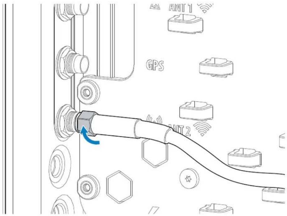
- Secure cables with cable ties.

- Remove two screws securing the antenna access door on the back of the Vehicle Dock.
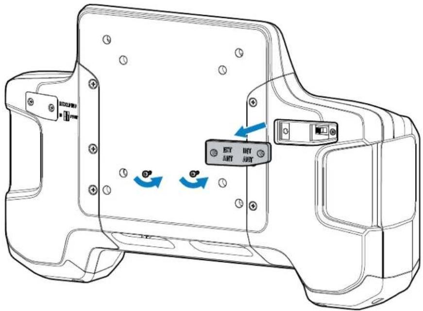
- Ensure the switch is to the EXT ANT position.
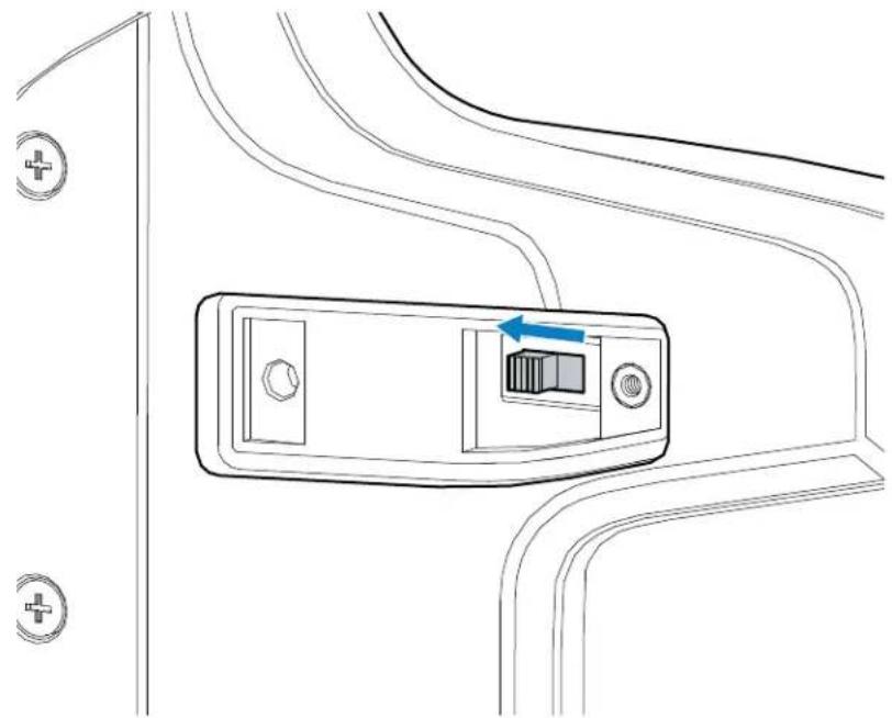
- Replace the antenna access door.
- Set antenna configuration using the PTA Settings application on the ET6x. See the ET6x Product Reference Guide.
Installing the Screen Blanking Cable
To use screen blanking, connect the Screen Blanking cable (p/n CA1300) to the Vehicle Dock RS-232 connector and to the a switch on the vehicle. Activate this switch electrically (for example, motion sensor) or mechanically (for example, pedal switch) when the vehicle is in motion.
The screen blanking feature makes use of the RS-232 port to monitor electrical relay closure. When enabled, the CTS/RTS pins of the RS-232 port are continuously monitored by the screen blanking application.

When the vehicle is in motion, the switch closes the circuit, allowing data packets to be sent or received through the RTS and CTS pins. The computer detects that the circuit is closed and turns off the screen. When the vehicle is not in motion, the switch opens the circuit, preventing data packets from being sent or received. The computer detects that the circuit is open and turns on the screen.
- Open the Access Door.
- Route the Screen Blanking Cable up through the bottom of the Vehicle Dock.
- Remove the RS-232 connector cover.
- Connect the cable to the RS-232 port on the inside of the Vehicle Dock.
- Tighten the thumb screws to ensure proper water sealing.
-
Secure cable with cable ties.
-
Remove two screws securing the RS-232 access door on the back of the Vehicle Dock.
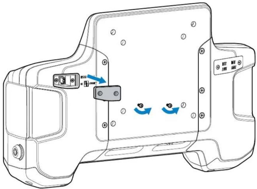
- Move the jumper to the bottom two pins.

- Replace the RS-232 access door.
Installing the Keyboard Mounting Bracket
Use the optional Keyboard Mounting Bracket to mount a keyboard onto the Vehicle Dock.

| 1 Mounting holes | |
| 2 Locking knobs | |
| 3 Tray |

NOTE: Mount the Vehicle Dock to third-party mounting systems that use 100 mm or 75 mm VESA mounting patterns.
- Align the Vehicle Dock mounting holes with the keyboard bracket (4) third-party bracket (5) mounting holes.

- Insert four bolts (1) into the Vehicle Dock bolt holes and through the brackets (4).
- Place the washers (2) onto the bolts.
- Secure with four lock nuts (3).
Installing the Keyboard Cable
Two keyboard require installation of a USB cable prior to installation.

NOTE: For CBL-ET-KBUSB1-01, and CBL-ET-KBUSB2-01 only.
To install the keyboard USB cable:
- Remove the four screws securing the cable cover to the keyboard.
Vehicle Dock Installation
- Turn the cable connector at a right angle as shown below and insert the connector (with connector clips on top) into the keyboard housing.
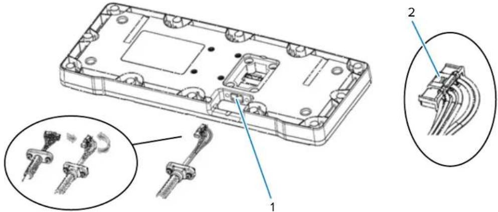
| Option Description |
| 1 Keyboard housing |
| 2 Connector clips |
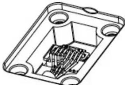
-
Turn the cable connector straight (with connector clips on top) and plug the connector in the keyboard.
-
Secure the cable retention to the housing using the two retention screws. Torque the M3 screws to 6kgf-cm (5.2 lbs-in).
-
Gently push the wires downward and install the cable cover. Torque the four M3 screws to 6kgf-cm (5.2 lbs-in).

| Option Description | |
| 1 Cable cover | with M3 screws (4) |
Mounting the Keyboard
The Keyboard Mount supports installation of the USB keyboards.
To mount the keyboard onto the Keyboard Mount tray:
- Align the keyboard with the tray on the Keyboard Mount.

Vehicle Dock Installation
- Insert four screws through the tray and into the keyboard.
- Secure screws.
- Route keyboard cable through the bottom of the Vehicle Dock.
- Plug the USB connector into one of the USB ports.

CAUTION: Ensure that the thumb-screws on the RS-232 connector are tight to ensure water sealing.
- If required, remove the RS-232 connector cover and plug the RS-232 connector into the RS-232 port.
- Tighten connector thumb-screws.
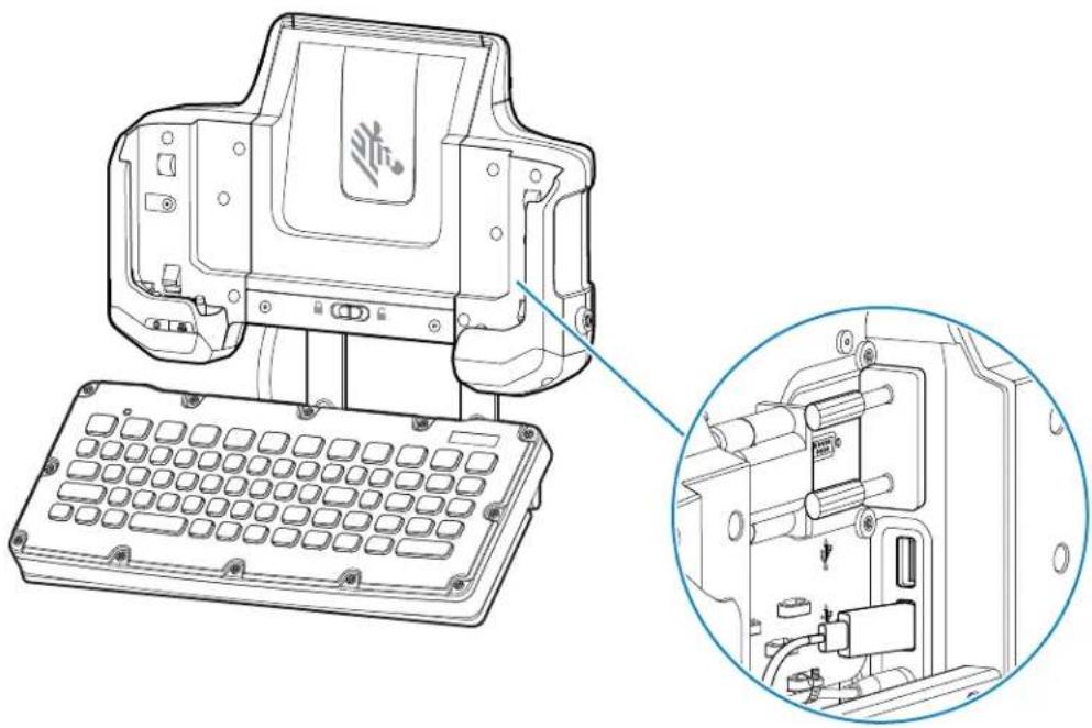
- Secure the cable(s) using cable ties.
- Use the adjustment knows to position the keyboard tray angle.
- To adjust the keyboard tray position, loosen the right and left locking knobs two full turns.
- Rotate the keyboard tray to the desired position and tighten the keyboard tray locking knobs to secure the tray in position.
Installing a Keyboard on a RAM Mount
Use RAM Mounts if the keyboard is not attached to the Vehicle Dock, but mounted remotely from the Vehicle Dock at another place on the truck.

CAUTION: If mounting to a thin surface such as drywall or plywood, a reinforcing plate is required.
| Part Number Description | |
| MT3502 2.25" Ball base | |
| M4x14 Four screws with captive washers |
Vehicle Dock Installation
To mount the RAM mount on the keyboard:
- Align the four holes on the ball base plate with the four holes on the keyboard bottom.
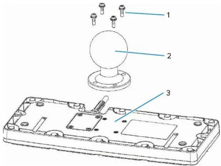
| Option Description | |
| 1 Screws (4) | |
| 2 Ball base | |
| 3 Keyboard bottom | |
- Secure using the four screws with captive washers.
Keyboard Heater
The USB keyboards contain three internal USB heaters that prevent damage when operating in condensing environments:
- Low - this heater operates with the standard USB cable, and turns on when the temperature is below 20° C (68°F).
- Normal - this heater operates with the Y-cable, and turns on when the temperature is below 15° C (59°F).
- High - this heater operates with the Y-cable, and turns on when the temperature is below 5° C (41° F).
Accessories
This section provides information for using the accessories for the device.
The following table lists the accessories available for the device.
Table 19 ET6x Accessories
| Accessory Part Number Description | ||
| Vehicle Dock | ||
| Vehicle Charging Dock CRD-ET6X-VEHDK-CON-1 | Provides tablet charging, USB communication, and Ethernet communication. Includes set of 10-32 nuts (4), screws (4), washers (4), and cable ties. Mount not included. Supports VESA 100 x 100, 100 x 50, and 75 x 75. | |
| Vehicle Charging Dock with Antenna Pass Through | CRD-ET6X-VEHDK-PTA-01 | Provides tablet charging, USB communication, Ethernet communication, and antenna pass through. Requires power supply (PWR-BGA15V45W-UC-WW) with country-specific AC line cord. Includes set of 10-32 nuts (4), screws (4), washers (4), and cable ties. Supports VESA 100 x 100, 100 x 50, and 75 x 75. |
| Desk Stand for Vehicle Dock STND-ET-DESK-01 Provides mounting the Vehicle Dock for use on a desk or tablet. | ||
| DC/DC Power Supply PS1370 Powers a Vehicle Dock and an ET60 from a 19 to 90 VDC power source. Must be used with the ET60 with installed Touch Screen Heater. | ||
| DC/DC Power Supply (9 VDC to 60 VDC) | 450083 Accepts 9V to 60V (9A maximum) vehicle power and converts it to 13.2V output. Requires Direct Wire Power Cable Kit (300039). | |
| DC/DC Power Supply (50 VDC to 150 VDC) | 450084 Accepts 50V to 150V (2A maximum) vehicle power and converts it to 13.2V output. Requires Direct Wire Power Cable Kit (300039). | |
| DC Power Adapter Cable CBL-ET-ADP1-1 For powering the Vehicle Dock from an existing VC80 installation. | ||
| DC Power Adapter CBL-ET6-ADPA2-1 Connects the DC/DC Power Supply (PS1370) to the Vehicle Dock. | ||
| LXE/Honeywell Power Adapter Cable | ACC-PWRCBL01 Allows ET6X Vehicle Dock to be powered from a legacy LXE/Honeywell power cable. Requires DC/DC Power Supply (450083/84) and Direct Wire Power Cable Kit (300039). | |
| Dire Wire Kit 300039 Powers the Vehicle Dock for new installations.Contains: DC power cord, fuse holder cable, fuse, two butt splice connectors, and two ring terminals. | ||
| Cigarette Lighter Adapter (CLA) cable | 450143 Provides power to the vehicle dock from a vehicle cigarette lighter port. | |
| Keyboard Mounting Bracket KT-KYBDTRAY-ET6X-01 | Mounts a USB keyboard to the Vehicle Dock. | |
| Keyboards | ||
| USB Warehouse QWERTY Keyboard | KYBD-QW-VC-01 USB | Warehouse Keyboard with QWERTY key layout. |
| USB Warehouse AZERTY Keyboard | KYBD-AZ-VC-01 USB | Warehouse Keyboard with AZERTY key layout. |
| USB Warehouse Keyboard with USB-A Cable | KYBD-QW-ET-S-1 USB | Warehouse Keyboard QWERTY with USB Type-A Cable |
| USB Keyboard Cable CBL-ET-KBUSB1-01 Connects USB Warehouse keyboard to the Vehicle Dock. | ||
| USB/RS-232 Keyboard Cable CBL-ET-KBUSB2-01 | Connects USB Warehouse keyboard with heater to Vehicle Dock. | |
| Soft Goods | ||
| Carry Handle with Stylus Slot and Coiled Stylus Tether | SG-ET8X-HANDLE1-01 | Allows user to carry the tablet. Requires ET6x Attachment Clips. |
| Detachable Shoulder Strap SG-ET8X-SHLDR1-01 | Allows user to carry the tablet. Requires ET6x Attachment Clips. | |
| ET6x Attachment Clips for Straps | SG-ET6X-DCLIPS-01 | Provides mounting of the Carry Handle or Shoulder Strap to the tablet. |
| ET6x Kickstand XBK-ET6X- | KCKSTD-01 | Provides working comfort for the tablet in the field and at a desk. The kickstand closes tightly when you are on the move, and it provides good ergonomics when the tablet is on flat surfaces. |
| Replacement Hand Strap SG-ET5X-RHTP1-01 | ||
| Power Supplies and Batteries | ||
| Standard 9.3 Ah Battery BTRY- | ET6XA-9AH-01 | Replacement standard battery. |
| Extended 18.7 Ah Battery BTRY- | ET6XA-18AH-01 | Replacement extended battery. |
| No Cells Battery | BTRY-ET6X-0AH-01 | Replacement no cell battery. |
| 12 VDC 6 A Power Supply | PWR-BGA15V45W-UC2-WW | Provide power to the tablet. Provides power to the tablet. Requires country specific AC line cord. |
| Stylus | ||
| Passive Stylus SG-STYLUS-TCX-MTL-03 | Passive stylus for use with the tablet (3-pack). | |
| Tether for Passive Stylus SG- | TC5NGTC7NG-TETHR-03 | Connects a Passive Stylus to the tablet. |
| Active Stylus and Stylus Holder | SG-ET8X-STYLUS1-01 | Provides easy writing, drawing, and navigation and accuracy with the thin tip and hovering capabilities. |
| Stylus Holder. SG-ET8X- | PENLOOP1-01 | Secures a stylus to the tablet. |
| Stylus Coil Tether SG-ET5X- | SLTETR-01 | Secures a stylus to the hand strap. |
| Miscellaneous | ||
| USB Port Door MISC-ET6X-USB-DOOR | Replacement USB port door. | |
Device Charging
Before using the tablet for the first time, connect it to an external power source to charge the battery.

NOTE: Battery-free tablets do not require charging.
Keep the tablet connected to the external power source until fully charged. The Charging Indicator LED turns green when the tablet is fully charged. You may use the tablet while it is charging.
To charge the main battery, connect the charging accessory to the appropriate power source.
Insert the device into the dock or attach the USB charger. The device turns on and begins charging. The Charging/Notification LED blinks amber while charging, then turns solid green when fully charged.
The battery charges from fully depleted to 90% in approximately 3.5 hours and from fully depleted to 100% in approximately 4.5 hours. In many cases, the 90% charge provides plenty of charge for daily use. A full 100% charge lasts for approximately 14 hours of use. To achieve the best charging results, use only Zebra charging accessories and batteries. Charge batteries at room temperature with the device in sleep mode.
Charging Temperature
Charge batteries in ambient temperatures.
Charge batteries in temperatures from 5°C to 40°C (41°F to 104°F). The device always performs battery charging in a safe and intelligent manner. At higher temperatures (e.g. approximately +37°C (+98°F)), the device may, for small periods of time, alternately enable and disable battery charging to keep the battery at acceptable temperatures. The device indicates when charging is disabled due to abnormal temperatures via its LED.
Charging Indicators
Charge the battery before using the device.
Table 20 Charging Indicators
| LED Indication | |
| Off Power is not supplied to the device. The device uses the no cell battery. | |
| Slow blinking orange(1 blink every 4 seconds) | The device is charging. |
| Slow blinking red(1 blink every 4 seconds) | The device is charging, but the battery is at the end of its useful life. |
| Fast blinking orange(2 blinks/second) | Charging error. Possible charging errors include:Temperature is too low or too high.Charging has gone on too long without completion (typically eight hours). |
| Fast blinking red(2 blinks/second) | Charging error and the battery is at the end of its useful life. Possible charging errors include:Temperature is too low or too high.Charging has gone on too long without completion (typically eight hours). |
| Solid Green Charging complete. | |
| Solid Red Charging is complete, but the battery is at the end of useful life. | |
| Blinking red(1 blink/second) | A Battery-free tablet is connected to external power. |
Vehicle Dock
The Vehicle Dock provides tablet charging, data communication, and antenna pass through (on specific configurations).

NOTE: Ensure that you follow the guidelines for battery safety described in the Battery Safety Guidelines on page 153.
Figure 26 Vehicle Dock Right View

| 1 Keys (remove prior to use) |
| 2 ANT 1 SMA pass-through connector |
| 3 GPS SMA pass-through connector |
| 4 ANT 2 SMA pass-through connector |
| 5 12 -15 VDC Power port |
| 6 Tablet retention |
| 7 Vehicle Dock Power LED |
| 8 Tablet connection LED |
| 9 Power and pass through antenna pogo pins |
| 10 Security lock |
| 11 Cable mounting tabs |
| 12 Mounting bolt holes (8) for VESA 75 x 75 mm or 100 x 100 mm pattern |
Figure 27 Vehicle Dock Left View

| 1 RS-232 port | (The Vehicle Dock ships with an RS-232 cover. Keep the cover in place at all times to prevent corrosion and preserve the water seal in RS232 connector) |
| 2 Tablet alignment rail | |
| 3 USB-A port | |
| 4 USB-A port | |
| 5 Tablet retention | |
| 6 USB pogo pins | |
| 7 Access door | release latch |
LED Indicators
Table 21 Vehicle Dock LED Indicators
| LED Status Description | ||
| LED | Green Power is applied to the Vehicle Dock.Vehicle Dock Power | |
| Off No power applied to the Vehicle Dock. | ||
| Tablet Connection LED | Green Tablet is properly seated in the Vehicle Dock. | |
| Flashing red | Tablet is in the Vehicle Dock but is not seated properly. | |
| Off Tablet is not in the Vehicle Dock. | ||
Inserting the Tablet into the Vehicle Dock
The Vehicle Dock secures the tablet and provides power and communication connections.
To insert the tablet:
- Close the Access Door.
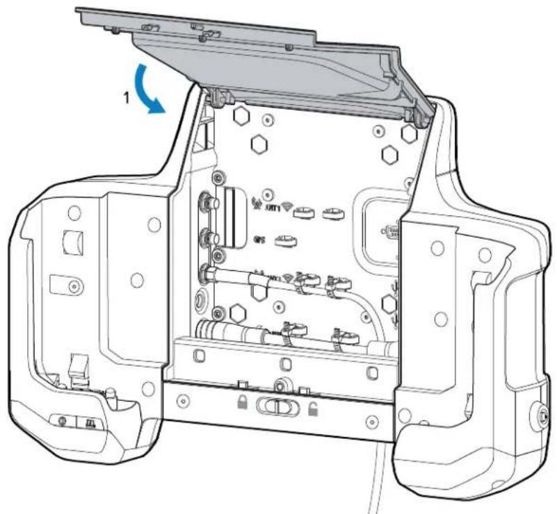
- Align the tablet with the dock alignment rails. Push the tablet down until it clicks into place.

- Turn the key to the lock position.
Removing the Tablet from the Vehicle Dock
After using the tablet in the Vehicle Dock, remove it to use in a mobile
If the Vehicle Dock is locked, use the key to unlock the dock before removing the tablet.
To remove the tablet from the Vehicle Dock:
- Turn the key to the unlock position.

- Press the tablet release latches.
The tablet ejects slightly.
- Lift the table out of the Vehicle Dock.
Desk Stand
The Desk Stand provides a method for using the Vehicle Dock on a desk.
Figure 28 Desk Stand
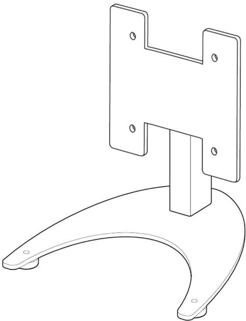
Installing the Vehicle Dock on the Desk Stand
Mount the Vehicle Dock onto the Desk Stand to use the Vehicle Dock on a desk or flat surface.

NOTE: The Vehicle Dock contains all required mounting hardware.
To mount the Vehicle Dock:
- Open the access door.
Accessories
- Align the mounting screw holes with the screw holes on the Desk Stand.
- Insert four bolts into the appropriate screw holes.
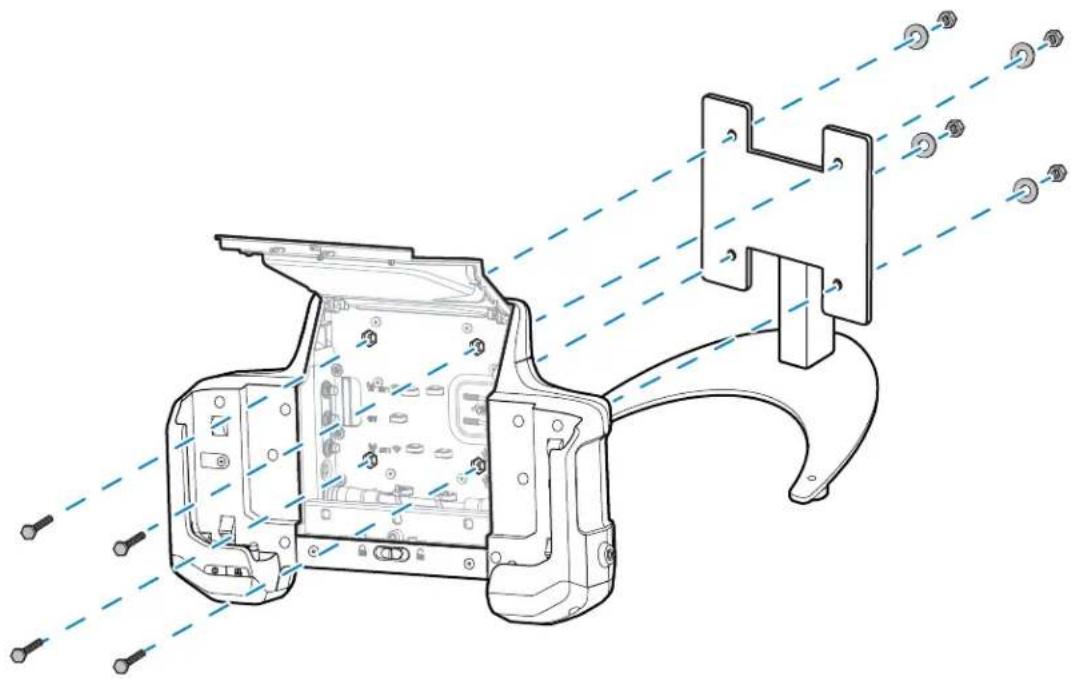
- Insert the washers onto the bolts.
- Secure using the four lock washers.
Setting Up the Desk Stand
With the Vehicle Dock installed on the Desk Stand, attach the power supply and optional keyboards. To set up the Desk Stand and Vehicle Dock:
- Open the Access Door.
- Route the power supply cable up through the bottom of the Vehicle Dock.
- Plug the connector into the power port.
- Route keyboard USB cable through the bottom of the Vehicle Dock.
- Plug the USB cable into one of the USB ports.
- Secure cables using the cable ties.
-
Close the Access Door.
-
Power the power supply into an AC outline.
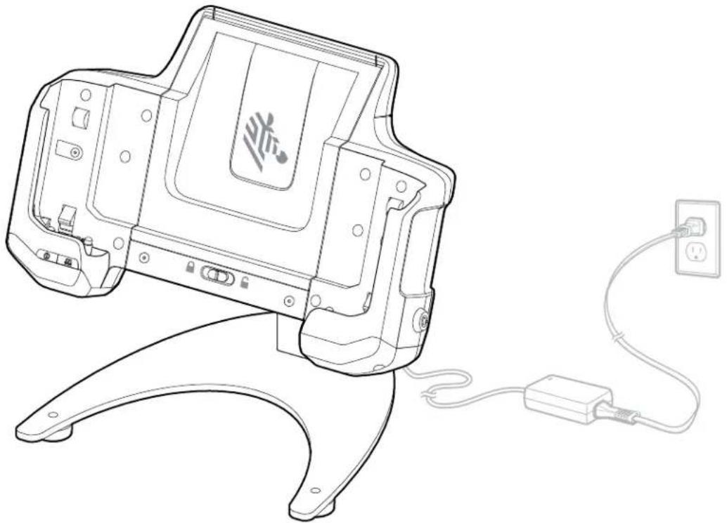
USB-C to AC Adapter
The USB-C to AC Adapter provides power to the tablet.

NOTE: Ensure that you follow the guidelines for battery safety described in the ET6x Product Reference Guide.

USB Keyboards
There are a number of USB keyboard that can be used with the tablet.
- QWERTY keyboard - Requires USB cable (CBL-ET-KBUSB1-01) or USB/RS232 Y-Cable (CBL-ET-KBUSB2-01)
- AZERTY keyboard - Requires USB cable (CBL-ET-KBUSB1-01) or USB/RS232 Y-Cable (CBL-ET-KBUSB2-01)
- USB QWERTY Keyboard (p/n KYBD-QW-ET-S-1) - QWERTY style keyboard with USB cable.
The keyboard can be mounted on the Vehicle Dock Keyboard Mount or on an external RAM mount.
Soft Handle
Attach the Soft Handle to carry the tablet.
The Soft Handle comes with a Stylus Slot and a Coiled Stylus Tether.
Figure 29 Soft Handle

Attaching the Soft Handle
The Soft Handle requires the D-Clips to attach to the tablet.

NOTE: To install the Soft Handle, the ET60/ET65 D-Clips are required. The D-Clips, and Soft Handle are each sold separately.
To install the Soft handle:
- Feed Soft Handle strap through buckle.

- Feed the Soft Handle strap through D-Clip.

- Feed the Soft Handle strap through buckle.

- Insert the D-Clips into the bottom of the tablet.

Use the Soft Handle to carry the tablet.
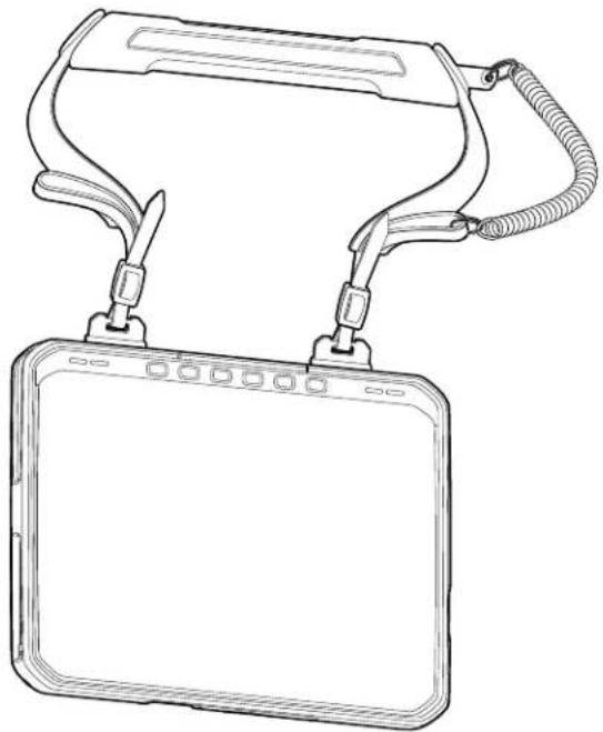
Attaching the Shoulder Strap to the Soft Handle
Attach the Shoulder Strap to the Soft Handle for additional carrying options.
To attach the Shoulder Strap:
Accessories
- Attach the clips of the Shoulder Strap to the loops on the Soft Handle.
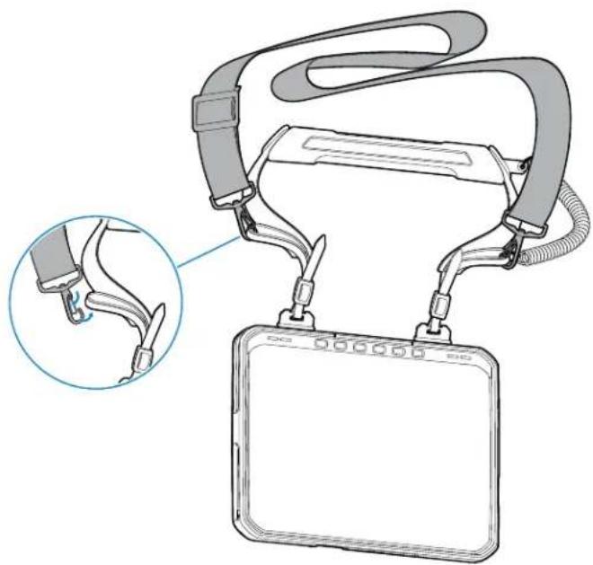
- Ensure that the clips are closed properly.
Removing the D-Clips
Remove the D-Clips to detach the Soft Handle or Shoulder Strap from the tablet.
- Lift the release latch.
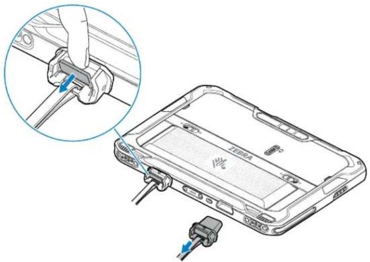
- Pull the D-Clip out of the tablet.
Shoulder Strap
Use the Shoulder Strap to carry the tablet.

NOTE: The Shoulder Strap requires ET60/ET65 D-Clips. The D-Clips are sold separately.
Figure 30 Shoulder Strap

Attaching the Shoulder Strap
The Shoulder Strap requires the D-Clips to attach to the tablet.

NOTE: To install the Shoulder Strap, the ET60/ET65 D-Clips are required. The D-Clips, and Shoulder Strap are each sold separately.
To attach the Shoulder Strap:
- Feed small strap through buckle.

- Feed the Soft Handle strap through D-Clip.
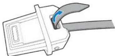
- Feed the Soft Handle strap through buckle.
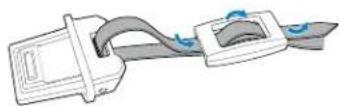
- Insert the D-Clips into the bottom of the tablet.

- Attach the Shoulder Strap clips to the loop in the small strap.

Removing the D-Clips
Remove the D-Clips to detach the Soft Handle or Shoulder Strap from the tablet.
- Lift the release latch.

- Pull the D-Clip out of the tablet.
Stylus Holder
The Stylus Holder mounts on the device and holds a stylus for easy availability.

NOTE: The Stylus Holder must be applied to the trapezoid areas on the back of the tablet.
Figure 31 Stylus Holder Mounting Locations
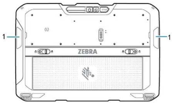
1 Trapezoid mounting areas
Installing the Stylus Holder
Install the Stylus Holder onto the tablet to hold a stylus for easy access.
To install the Stylus Holder:
Accessories
- Remove the adhesive backing.


- Using the cleaning cloth, wipe the area on the tablet.

- Align the Stylus Holder on to the tablet and press down to adhere to the tablet.
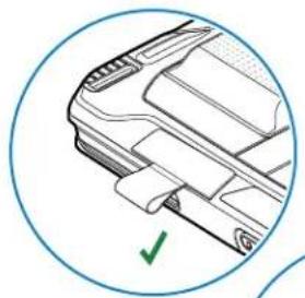

Application Deployment
This section provides an overview of device security, app development, and app management. It also provides instructions for installing apps and updating the device software.

NOTE: Ensure that the date is set correctly before installing certificates or when accessing secure websites.
Android Security
The device implements a set of security policies that determine whether an application is allowed to run and, if allowed, with what level of trust. To develop an application, you must know the security configuration of the device, and how to sign an application with the appropriate certificate to allow the application to run (and to run with the needed level of trust).

NOTE: Ensure the date is set correctly before installing certificates or when accessing secure web sites.
Secure Certificates
If the VPN or Wi-Fi networks rely on secure certificates, obtain the certificates and store them in the device's secure credential storage, before configuring access to the VPN or Wi-Fi networks.
If downloading the certificates from a web site, set a password for the credential storage. The device supports X.509 certificates saved in PKCS#12 key store files with a .p12 extension (if key store has a .pfx or other extension, change to .p12).
The device also installs any accompanying private key or certificate authority certificates contained in the key store.
Installing a Secure Certificate
If required by the VPN or Wi-Fi network, install a secure certificate on the device.
- Copy the certificate from the host computer to the root of the microSD card or the device's internal memory.
- Go to Settings.
- Touch Security > Encryption & credentials.
- Touch Install a certificate.
- Navigate to the location of the certificate file.
Application Deployment
- Touch the filename of the certificate to install.
- If prompted, enter the password for credential storage. If a password has not been set for the credential storage, enter a password for it twice, and then touch OK.
-
Enter a name for the certificate and in the Credential use drop-down, select VPN and apps or Wi-Fi.
-
Touch OK.
The certificate can now be used when connecting to a secure network. For security, the certificate is deleted from the microSD card or internal memory.
Android Development Tools
Development tools for Android include Android Studio, EMDK for Android, and StageNow.
Android Development Workstation
Android development tools are available at developer.android.com.
To start developing applications for the device, download Android Studio. Development can take place on a Microsoft® Windows®, Mac® OS X®, or Linux® operating system.
Applications are written in Java or Kotlin, but compiled and executed in the Dalvik virtual machine. Once the Java code is compiled cleanly, the developer tools make sure the application is packaged properly, including the AndroidManifest.xml file.
Android Studio contains a full featured IDE as well as SDK components required to develop Android applications.
Enabling Developer Options
The Developer options screen sets development-related settings. By default, the Developer Options are hidden.
- Go to Settings.
- Touch About phone.
- Scroll down to Build number.
- Tap Build number seven times.
The message You are now a developer! displays.
- Touch Back.
- Touch System > Developer options.
- Slide the USB debugging switch to the ON position.
EMDK for Android
EMDK for Android provides developers with tools to create business applications for enterprise mobile devices. It is designed for use with Google's Android Studio and includes Android class libraries such as Barcode, sample applications with source code, and the associated documentation.
EMDK for Android allows applications to take full advantage of the capabilities that Zebra devices have to offer. It embeds Profile Manager technology within Android Studio IDE, providing a GUI-based
Application Deployment
development tool designed specifically for Zebra devices. This allows fewer lines of code, resulting in reduced development time, effort, and errors.
See Also
For more information go to techdocs.zebra.com.
StageNow for Android
StageNow is Zebra's next-generation Android Staging Solution built on the MX platform. It allows quick and easy creation of device profiles, and can deploy to devices simply by scanning a barcode, reading a tag, or playing an audio file.
The StageNow Staging Solution includes the following components:
- The StageNow Workstation tool installs on the staging workstation (host computer) and lets the administrator easily create staging profiles for configuring device components, and perform other staging actions such as checking the condition of a target device to determine suitability for software upgrades or other activities. The StageNow Workstation stores profiles and other created content for later use.
- The StageNow Client resides on the device and provides a user interface for the staging operator to initiate staging. The operator uses one or more of the desired staging methods (print and scan a barcode, read an NFC tag or play an audio file) to deliver staging material to the device.
See Also
For more information go to techdocs.zebra.com.
GMS Restricted
GMS Restricted mode deactivates Google Mobile Services (GMS). All GMS apps are disabled on the device and communication with Google (analytics data collection and location services) is disabled.
Use StageNow to disable or enable GMS Restricted mode. After a device is in GMS Restricted mode, enable and disable individual GMS apps and services using StageNow. To ensure GMS Restricted mode persists after an Enterprise Reset, use the Persist Manager option in StageNow.
See Also
For more information on StageNow, refer to techdocs.zebra.com.
ADB USB Setup
To use the ADB, install the development SDK on the host computer then install the ADB and USB drivers.
Before installing the USB driver, make sure that the development SDK is installed on the host computer. Go to developer.android.com/sdk/index.html for details on setting up the development SDK.
The ADB and USB drivers for Windows and Linux are available on the Zebra Support Central web site at zebra.com/support. Download the ADB and USB Driver Setup package. Follow the instructions with the package to install the ADB and USB drivers for Windows and Linux.
Enabling USB Debugging
By default, USB debugging is disabled.
- Go to Settings.
- Touch About phone.
- Scroll down to Build number.
- Tap Build number seven times.
The message You are now a developer! appears.
-
Touch Back.
-
Touch System > Advanced > Developer options.
-
Slide the USB debugging switch to the ON position.
-
Touch OK.
-
Connect the device to the host computer using the Rugged Charge/USB Cable.
The Allow USB debugging? dialog box appears on the device.
If the device and host computer are connected for the first time, the Allow USB debugging? dialog box with the Always allow from this computer check box displays. Select the check box, if required.
-
Touch OK.
-
Touch OK or Allow.
-
On the host computer, navigate to the platform-tools folder and open a command prompt window.
-
Type adb devices.
The following displays:
List of devices attached
XXXXXXXXXXXXXX device
WhereXXXXXXXXXXXXXX is the device number.

NOTE: If device number does not appear, ensure that ADB drivers are installed properly.
- Return to the Home screen.
Entering Android Recovery Manually
Many of the update methods discussed in this section require putting the device into Android Recovery mode. If you are unable to enter Android Recovery mode through adb commands, use the following steps to manually enter Android Recovery mode.
-
Press and hold the Power button until the menu appears.
-
Touch Restart.
-
Press and hold the P3 button until the System Recovery screen displays.
Application Installation Methods
After an application is developed, install the application onto the device using one of the supported methods.
- USB Connection, go to
- Android Debug Bridge, go to
- Wireless Android Debug Bridge, go to
- microSD card. go to
- Mobile device management (MDM) platforms that have application provisioning. Refer to the MDM software documentation for details.
Installing Applications Using the USB Connection
Use the USB connection to install applications onto the device.

CAUTION—PRODUCT DAMAGE: When connecting the device to a host computer and mounting the microSD card, follow the host computer's instructions for connecting and disconnecting USB devices, to avoid damaging or corrupting files.
- Connect the device to a host computer using the USB-C cable.
- On the device, pull down the Notification panel and touch Charging this device via USB. By default, No data transfer is selected.
- Touch File Transfer.
- On the host computer, open a file explorer application.

CAUTION—PRODUCT DAMAGE: Carefully follow the host computer's instructions to unmount the microSD card and disconnect USB devices correctly to avoid losing information.
-
On the host computer, copy the application APK file from the host computer to the device.
-
Disconnect the device from the host computer.
-
Swipe the screen up and select to view files on the Internal Storage.
-
Locate the application APK file.
-
Touch the application file.
-
Touch Continue to install the app or Cancel to stop the installation.
-
To confirm installation and accept what the application affects, touch Install otherwise touch Cancel.
-
Touch Open to open the application or Done to exit the installation process.
The application appears in the App list.
Installing Applications Using the Android Debug Bridge
Use ADB commands to install applications onto the device.

CAUTION—PRODUCT DAMAGE: When connecting the device to a host computer and mounting the microSD card, follow the host computer's instructions for connecting and disconnecting USB devices to avoid damaging or corrupting files.
- Ensure that the ADB drivers are installed on the host computer.
- Connect the device to a host computer using a USB cable.
- Go to Settings.
- Touch System > Advanced > Developer options.
- Slide the USB debugging switch to the ON position.
- Touch USB Debugging. A check appears in the check box. The Allow USB debugging? dialog box appears.
- Touch OK.
- On the host computer, navigate to the platform-tools folder and open a command prompt window.
- Type adb install
.
where:= the path and filename of the apk file. - Disconnect the USB-C cable from the device.
Installing Applications Using a microSD Card
Use a microSD card to install applications on your device.

CAUTION—PRODUCT DAMAGE: When connecting the device to a host computer and mounting the microSD card, follow the host computer's instructions for connecting and disconnecting USB devices, to avoid damaging or corrupting files.
It is strongly recommended that prior to use, you must format the microSD card on the device.
-
Copy the APK file to the root of the microSD card.
-
Copy the APK file to a microSD card using a host computer (see USB Communication for more information), and then install the microSD card into the device (see Replacing the microSD Card for more information).
-
Connect the device with a microSD card already installed to the host computer, and copy the .apk file to the microSD card. See USB Communication for more information. Disconnect the device from the host computer.
-
Connect the device to a host computer using USB.
- Copy the application APK file from the host computer to the microSD card.
- Remove the microSD card from the host computer.
- Press and hold the Power button on the device until the menu appears.
- Touch Power off.
- Press the two battery latches in.
Application Deployment
- Lift the battery from the device.
- Lift the access door.
- Insert the microSD card.
- Replace the access door.
- Insert the battery, bottom first, into the battery compartment in the back of the device.
- Press the battery down until the battery release latches snap into place.
-
Press and hold Power to turn on the device.
-
Swipe the screen up and select to view files on the microSD card.
-
Locate the application APK file.
-
Touch the application file.
-
Touch Continue to install the app or Cancel to stop the installation.
-
To confirm installation and accept what the application affects, touch Install. Otherwise, touch Cancel.
-
Touch Open to open the application or Done to exit the installation process.
The application appears in the App list.
Uninstalling an Application
Free up device memory by removing unused apps.
- Go to Settings.
- Touch Apps & notifications.
- Touch See all apps to view all apps in the list.
- Scroll through the list to the app.
- Touch the app. The App info screen appears.
- Touch Uninstall.
- Touch OK to confirm.
Android System Update
System Update packages can contain either partial or complete updates for the operating system. Zebra distributes the System Update packages on the Zebra Support & Downloads website. Perform a system update using either a microSD card or using ADB.
Performing a System Update Using a microSD Card
It is strongly recommended that prior to use, you must format the microSD card on the device.
Go to the Zebra Support & Downloads web site at zebra.com/support and download the appropriate System Update package to a host computer.
Application Deployment
-
Copy the System Update zip file to the root of the microSD card.
-
Copy the ZIP file to a microSD card using a host computer, and then install the microSD card into the device. See Getting Started for information on installing the microSD card.
-
Connect the device with a microSD card already installed to the host computer, copy the ZIP file to the microSD card, and then disconnect the device from the host computer.
-
Press and hold Power until the menu appears.
- Touch Restart.
- Press and hold PTT until the device vibrates.
The System Recovery screen appears.
- Press Volume Up and Volume Down to navigate to Apply upgrade from SD card.
- Press Power.
- Press Volume Up and Volume Down to navigate to the System Update file.
- Press Power. The System Update installs and then the device returns to the Recovery screen.
- Press Power to reboot the device.
Performing a System Update Using ADB
Use ADB to perform a system update.
- Connect the device to a host computer using a USB-C cable or by inserting the device into the 1-Slot USB/Ethernet Cradle.
- Go to Settings.
- Touch System > Advanced > Developer options.
- Slide the USB debugging switch to the ON position.
- If the device and host computer are connected for the first time, the Allow USB debugging? dialog box with the Always allow from this computer check box displays. Select the check box, if required.
- Touch OK.
- On the host computer, navigate to the platform-tools folder and open a command prompt window.
- Type adb devices.

NOTE: If the device number does not appear, ensure that the ADB drivers are installed properly.
9. Type adb reboot recovery.
10. Press Enter.
The System Recovery screen appears on the device.
- Press Volume Up and Volume Down to navigate to Apply upgrade from ADB.
- Press Power.
- On the host computer command prompt window type adb sideload
. where: = the path and filename of the zip file.
14. Press Enter.
The System Update installs (progress appears as a percentage in the Command Prompt window) and then the System Recovery screen appears on the device.
- Press Power to reboot the device.
Verifying System Update Installation
Verify that the system update was successful.
- Go to Settings.
- Touch About phone.
- Scroll down to Build number.
- Ensure that the build number matches the new system update package file number.
Android Enterprise Reset
An Enterprise Reset erases all user data in the /data partition, including data in the primary storage locations (/sdcard and emulated storage), while preserving the contents of the /enterprise folder and its subfolders. The contents of the /enterprise folder and its subfolders are preserved. Zebra distributes the Enterprise Reset packages on the Zebra Support & Downloads website.

NOTE: This reset cannot be performed using wireless ADB.
Before performing an Enterprise Reset, provision all necessary configuration files and restore after the reset.
Performing an Enterprise Reset from Device Settings
Perform an Enterprise Reset from the device settings.
- Go to Settings.
- Touch System > Reset Options > Erase all data (enterprise reset).
- Touch Erase all data twice to confirm the Enterprise Reset.
Performing an Enterprise Reset Using a microSD Card
It is strongly recommended that prior to use, you must format the microSD card on the device.
-
Copy the Enterprise Reset zip file to the root of the microSD card.
-
Copy the zip file to a microSD card using a host computer and then install the microSD card into the device. See Getting Started for more information.
-
Connect the device with a microSD card already installed to the host computer and copy zip file to the microSD card. See USB Communication for more information. Disconnect the device from the host computer.
-
Press and hold Power until the menu appears.
- Touch Restart.
Application Deployment
- Press and hold PTT until the device vibrates.
The System Recovery screen appears. - Press Volume Up and Volume Down to navigate to Apply upgrade from SD card.
- Press Power.
- Press Volume Up and Volume Down to navigate to the Enterprise Reset file.
- Press Power.
The Enterprise Reset occurs and then the device returns to the Recovery screen. - Press Power to reboot the device.
Performing an Enterprise Reset Using ADB
Perform an Enterprise Reset using ADB.
- Connect the device to a host computer using the Rugged Charge/USB cable or by inserting the device into the 1-Slot USB/Charge Only Cradle.
- Connect the cable or cradle to the host computer.
- Go to Settings.
- Touch System > Advanced > Developer options.
- Slide the USB debugging switch to the ON position.
- If the device and host computer are connected for the first time, the Allow USB debugging? dialog box with the Always allow from this computer check box displays. Select the check box, if required.
- Touch OK.
- On the host computer, navigate to the platform-tools folder and open a command prompt window.
- Type adb reboot recovery.
- Press Enter.
The System Recovery screen appears on the device.

NOTE: If you are not able to enter Android Recovery mode through the adb command, go to Entering Android Recovery Manually.
- Press Volume Up and Volume Down to navigate to Apply upgrade from ADB.
- Press Power.
- On the host computer command prompt window type adb sideload
where: = the path and filename of the zip file. - Press Enter.
- Press Power to reboot the device.
The Enterprise Reset package installs and then the System Recovery screen appears on the device.
Android Factory Reset
A Factory Reset erases all data in the /data and /enterprise partitions in internal storage and clears all device settings. A Factory Reset returns the device to the last installed operating system image. To
revert to a previous operating system version, re-install that operating system image. Zebra distributes the Factory Reset packages on the Zebra Support & Downloads website.
Performing a Factory Reset Using microSD Card
Go to the Zebra Support & Downloads web site at zebra.com/support and download the appropriate Factory Reset file to a host computer.
-
Copy the Factory Reset zip file to the root of the microSD card.
-
Copy the zip file to a microSD card using a host computer and then installing the microSD card into the device. See Getting Started on page 5 for more information.
-
Connect the device with a microSD card already installed to the host computer, copy zip file to the microSD card, and then disconnect the device from the host computer.
-
Press and hold Power until the menu appears.
- Touch Restart.
- Press and hold P3 until the Android Recovery screen appears.
- Press + and - to navigate to Apply upgrade from SD card.
- Press Power.
- Press + and - to navigate to the Factory Reset file.
- Press Power.
The Factory Reset occurs and then the device returns to the Recovery screen.
- Press Power to reboot the device.
Performing a Factory Reset Using ADB
A Factory Rest can be performed using ADB commands.
Go to the Zebra Support & Downloads web site at zebra.com/support and download the appropriate Factory Reset file to a host computer.
- Connect the device to a host computer using a USB-C cable.
- Go to Settings.
- Touch System > Developer options.
- Slide the USB debugging switch to the ON position.
- Touch OK.
-
Type adb devices.
The following displays: -
If the device and host computer are connected for the first time, the Allow USB debugging? dialog box with the Always allow from this computer check box displays. Select the check box, if required.
-
On the host computer, navigate to the platform-tools folder and open a command prompt window.
List of devices attached
XXXXXXXXXXXXXX device
WhereXXXXXXXXXXXXX is the device number.

NOTE: If the device number does not appear, ensure that the ADB drivers are installed properly.
- Type:
adb reboot recovery
- Press Enter.
The System Recovery screen appears on the device.
-
Press + and - to navigate to Apply upgrade from ADB.
-
Press Power.
-
On the host computer command prompt window typeadb sideload
.
where:
- Press Enter.
The Factory Reset package installs, and then the System Recovery screen appears on the device.
- Press Power to reboot the device.
Android Storage
The device contains multiple types of file storage.
• Random Access Memory (RAM)
- On-device Storage
- Internal storage
- External storage (microSD card)
- Enterprise folder.

NOTE: It is recommended to install a microSD card on the device due to limited internal storage space.
Random Access Memory
Executing programs use RAM to store data. Data stored in RAM is lost upon a reset.
The operating system manages how applications use RAM. It only allows applications and component processes and services to use RAM when required. It may cache recently used processes in RAM, so they restart more quickly when opened again, but it will erase the cache if it needs the RAM for new activities.
The screen displays the amount of used and free RAM.
• Performance - Indicates memory performance.
- Total memory - Indicates the total amount of RAM available.
- Average used (%) - Indicates the average amount of memory (as a percentage) used during the period of time selected (default - 3 hours).
• Free - Indicates the total amount of unused RAM.
- Memory used by apps - Touch to view RAM usage by individual apps.
Viewing Memory
View the amount of memory used and free RAM.
- Go to Settings.
- Touch System > Developer options.
- Touch Memory.
Internal Storage
The device has internal storage. The internal storage content can be viewed and files copied to and from when the device is connected to a host computer. Some applications are designed to be stored on the internal storage rather than in internal memory.
Viewing Internal Storage
View available and used internal storage on the device.
- Go to Settings.
- Touch Storage.
Internal Storage displays the total amount of space on internal storage and amount used.
If the device has removable storage installed, touch Internal shared storage to display the amount of internal storage used by apps, photos, videos, audio, and other files.
Enterprise Folder
The Enterprise folder (within internal flash) is a super-persistent storage that is persistent after a reset and an Enterprise Reset.
The Enterprise folder is erased during a Factory Reset. The Enterprise folder is used for deployment and device-unique data. The Enterprise folder is approximately 128 MB (formatted). Applications can persist data after an Enterprise Reset by saving data to the enterprise/user folder. The folder is ext4 formatted and is only accessible from a host computer using ADB or from an MDM.
External Storage
The device can have a removable microSD card. The microSD card content can be viewed and files copied to and from when the device is connected to a host computer. The device can have a removable USB drive. The USB drive content can be viewed and files copied to and from when the device is connected to a host computer.
Viewing External Storage
Portable storage displays the total amount of space on the installed microSD card or USB drive and the amount used.
- Go to Settings.
-
Touch Storage.
Touch General USB Drive to view the contents of the card.
Touch SD card to view the contents of the card. -
To unmount the microSD card, touch ▲
- To unmount the USB drive, touch ▲
Formatting a microSD Card as Portable Storage
Format a microSD card as portable storage for the device.
- Touch SD card.
- Touch ➤ Storage settings.
- Touch Format.
- Touch ERASE & FORMAT.
- Touch DONE.
Formatting a microSD Card as Internal Memory
You can format a microSD card as internal memory to increase the actual amount of the device's internal memory. Once formatted, the microSD card can only be read by this device.

NOTE: The suggested maximum SD card size is 128 GB when using internal storage.
- Touch SD card.
- Touch ➤ Storage settings.
- Touch Format as internal.
- Touch ERASE & FORMAT.
- Touch DONE.
Enterprise Folder
The Enterprise folder (within internal flash) is a super-persistent storage that is persistent after a reset and an Enterprise Reset.
The Enterprise folder is erased during a Factory Reset. The Enterprise folder is used for deployment and device-unique data. The Enterprise folder is approximately 128 MB (formatted). Applications can persist data after an Enterprise Reset by saving data to the enterprise/user folder. The folder is ext4 formatted and is only accessible from a host computer using ADB or from an MDM.
Managing Apps
Apps use two kinds of memory: storage memory and RAM. Apps use storage memory for themselves and any files, settings, and other data they use. They also use RAM when they are running.
- Go to Settings.
- Touch Apps & notifications.
- Touch See all XX apps to view all apps on the device.
- Touch ➤ Show system to include system processes in the list.
Application Deployment
- Touch an app, process, or service in the list to open a screen with details about it and, depending on the item, to change its settings, permissions, notifications and to force stop or uninstall it.
App Details
Apps have different kinds of information and controls.
- Force stop - Stop an app.
- Disable - Disable an app.
- Uninstall - Remove the app and all of its data and settings from the device.
- Notifications - Set the app notification settings.
- Permissions - Lists the areas on the device that the app has access to.
• Storage & cache - Lists how much information is stored and includes buttons for clearing it. - Mobile data & Wi-Fi - Provides information about data consumed by an app.
- Mobile data & Wi-Fi - Provides information about data consumed by an app. Mobile data not supported.
-
Advanced
-
Screen time - Displays the amount of time the app has displayed on the screen.
- Battery - Lists the amount of computing power used by the app.
- Open by default - If you have configured an app to launch certain file types by default, you can clear that setting here.
- Display over other apps - Allows an app to display on top of other apps.
- App details - Provides a link to additional app details on the Play store.
- Additional settings in the app - Opens settings in the app.
- Modify system settings - Allows an app to modify the system settings.
Managing Downloads
Files and apps downloaded using the Browser or Email are stored on the USB drive or Internal storage in the Download directory. Use the Downloads app to view, open, or delete downloaded items. Files and apps downloaded using the Browser or Email are stored on the microSD card or Internal storage in the Download directory. Use the Downloads app to view, open, or delete downloaded items.
- Swipe the screen up and touch
- Touch ≡ Downloads.
- Touch and hold an item, select items to delete and touch ▪ The item is deleted from the device.
Maintenance and Troubleshooting
This section includes instructions on cleaning and storing the device, and provides troubleshooting solutions for potential problems during operation.
Maintaining the Device
Follow these guidelines to maintain the device properly.
For trouble-free service, observe the following tips when using the device:
- To avoid scratching the screen, use a Zebra approved capacitive compatible stylus intended for use with a touch-sensitive screen. Never use an actual pen or pencil or other sharp object on the surface of the device screen.
- The touch-sensitive screen of the device is glass. Do not drop the device or subject it to strong impact.
- Protect the device from temperature extremes. Do not leave it on the dashboard of a car on a hot day, and keep it away from heat sources.
- Do not store the device in any location that is dusty, damp, or wet.
- Use a soft lens cloth to clean the device. If the surface of the device screen becomes soiled, clean it with a soft cloth moistened with an approved cleanser.
- Periodically replace the rechargeable battery to ensure maximum battery life and product performance. Battery life depends on individual usage patterns.
- A screen protector is applied to the device. Zebra recommends using a screen protector to minimize wear and tear. Screen protectors enhance the usability and durability of touch screen displays. Benefits include:
• Protection from scratches and gouges
- Durable writing and touch surface with tactile feel
- Abrasion and chemical resistance
- Glare reduction
- Keeping the device's screen looking new
- Quick and easy installation.
Battery Safety Guidelines
To use the device safely, you must follow the battery guidelines.
- The area in which the units are charged should be clear of debris and combustible materials or chemicals. Particular care should be taken where the device is charged in a non-commercial environment.
- Follow battery usage, storage, and charging guidelines found in this guide.
- Improper battery use may result in a fire, explosion, or other hazard.
- To charge the mobile device battery, the ambient battery and charger temperatures must be between 0°C and +40°C ( +32°F and +104°F ).
- Do not use incompatible batteries and chargers, including non-Zebra batteries and chargers. Use of an incompatible battery or charger may present a risk of fire, explosion, leakage, or other hazard. If you have any questions about the compatibility of a battery or a charger, contact the Global Customer Support Center.
- For devices that utilize a USB port as a charging source, the device shall only be connected to products that bear the USB-IF logo or have completed the USB-IF compliance program.
- Do not disassemble or open, crush, bend or deform, puncture, or shred the battery.
- Severe impact from dropping any battery-operated device on a hard surface could cause the battery to overheat.
- Do not short circuit a battery or allow metallic or conductive objects to contact the battery terminals.
- Do not modify or remanufacture, attempt to insert foreign objects into the battery, immerse or expose to water or other liquids, or expose to fire, explosion, or other hazard.
- Do not leave or store the equipment in or near areas that might get very hot, such as in a parked vehicle or near a radiator or other heat source. Do not place battery into a microwave oven or dryer.
- Battery usage by children should be supervised.
- Please follow local regulations to properly dispose of used rechargeable batteries.
- Do not dispose of batteries in fire.
- In the event of a battery leak, do not allow the liquid to come in contact with the skin or eyes. If contact has been made, wash the affected area with water for 15 minutes, and seek medical advice.
- If you suspect damage to your equipment or battery, contact Customer Support to arrange for inspection.
Best Practices for Enterprise Mobile Computing Devices Operating in Hot Environments and Direct Sunlight
Exceeding the operating temperature by external hot environments will cause the device's thermal sensor to notify the user of a shutdown of the WAN modem or shutdown the device until the device's temperature returns to the operational temperature range.
- Avoid direct sunlight to the device - The easiest way to prevent overheating is to keep the device out of direct sunlight. The device absorbs light and heat from the sun and retains it, getting hotter the longer it remains in sunlight and heat.
- Avoid leaving the device in a vehicle on a hot day or hot surface - Similar to leaving the device out in direct sunlight, the device will also absorb the thermal energy from a hot surface or when left on the
Maintenance and Troubleshooting
dashboard of a vehicle or seat, getting warmer the longer it remains on the hot surface or inside the hot vehicle.
- Turn off unused apps on the device. Open, unused apps running in the background can cause the device to work harder, which in turn may cause it to heat up. This will also improve your mobile computer device's battery life performance.
- Avoid turning your screen brightness up - Just the same as running background apps, turning your brightness up will force your battery to work harder and create more heat. Minimizing your screen brightness may extend operating the mobile computer device in hot environments.
Approved Cleaning and Disinfectant Agents
Use pre-moistened wipes, and do not allow liquid cleaner to pool.

CAUTION: not use quaternary ammonia wipes.
100% of the active ingredients in any cleaner must consist of one or some combination of the following:
- isopropyl alcohol
- Denatured Alcohol
- 50/50 mixture of water and bleach (see important note below)
- 50/50 mixture of water and hydrogen peroxide
• Lysol disinfectant spray
• Disinfecting wipe with Alkyl C12-C18

IMPORTANT:
When using sodium hypochlorite (bleach) based products always follow the manufacturer's recommended instructions: use gloves during application and remove the residue afterward with a damp alcohol cloth or a cotton swab to avoid prolonged skin contact while handling the device. Due to the powerful oxidizing nature of sodium hypochlorite, the metal surfaces on the device are prone to oxidation (corrosion) when exposed to this chemical in liquid form (including wipes).
In the event that these types of disinfectants come in contact with metal on the device, prompt removal with an alcohol-dampened cloth or cotton swab after the cleaning step is critical.
Cleaning Instructions

CAUTION: Always wear eye protection. Read the warning label on alcohol product before using. If you have to use any other solution for medical reasons please contact the Global Customer Support Center for more information.

WARNING: Avoid exposing this product to contact with hot oil or other flammable liquids. If such exposure occurs, unplug the device and clean the product immediately in accordance with these guidelines.
Approved Cleanser Active Ingredients
100% of the active ingredients in any cleaner must consist of one or some combination of the following: isopropyl alcohol, bleach/sodium hypochlorite 1 (see important note below), hydrogen peroxide, ammonium chloride, or mild dish soap.

IMPORTANT: Use pre-moistened wipes and do not allow liquid cleaner to pool.
Due to the powerful oxidizing nature of sodium hypochlorite, the metal surfaces on the device are prone to oxidation (corrosion) when exposed to this chemical in the liquid form (including wipes). In the event that these type of disinfectants come in contact with metal on the device, prompt removal with an alcohol-dampened cloth or cotton swab after the cleaning step is critical.
Approved cleaners include:
• Purell Ethanol Wipes
• 409 Glass Cleaner
- Windex Blue
Harmful Ingredients
The following chemicals are known to damage the plastics on the device and should not come in contact with the device: acetone; ketones; ethers; aromatic and chlorinated hydrocarbons; aqueous or alcoholic alkaline solutions; ethanolamine; toluene; trichloroethylene; benzene; carbolic acid and TB-lysoform.
Many vinyl gloves contain phthalate additives, which are often not recommended for medical use and are known to be harmful to the housing of the device.
Special Cleaning Notes
Do not handle the device while wearing vinyl gloves containing phthalates. Remove vinyl gloves and wash hands to eliminate any residue left from the gloves.
If products containing any of the harmful ingredients listed above are used prior to handling the device, such as a hand sanitizer that contains ethanolamine, hands must be completely dry before handling the device to prevent damage to the device.

IMPORTANT: If the battery connectors are exposed to cleaning agents, thoroughly wipe off as much of the chemical as possible and clean with an alcohol wipe. It is also recommended to install the battery in the terminal prior to cleaning and disinfecting the device to help minimize buildup on the connectors. When using cleaning/disinfectant agents on the device, it is important to follow the directions prescribed by the cleaning/disinfectant agent manufacturer.
Cleaning Frequency
The cleaning frequency is at the customer's discretion due to the varied environments in which the mobile devices are used and may be cleaned as frequently as required. When dirt is visible, it is recommended to clean the mobile device to avoid the build-up of particles, which makes the device more difficult to clean later on.
For consistency and optimum image capture, it is recommended to clean the camera window periodically especially when used in environments prone to dirt or dust.
Device Cleaning Instructions
Do not apply liquid directly to the device. Dampen a soft cloth or use pre-moistened wipes. Do not wrap the device in the cloth or wipe, instead gently wipe the unit. Be careful not to let liquid pool around the display window or other places. Before use, allow the unit to air dry.

NOTE: For thorough cleaning, it is recommended to first remove all accessory attachments, such as hand straps or cradle cups from the mobile device and to clean them separately.
Display
The display can be wiped down with an approved alcohol wipe, but care should be taken not to allow any pooling of liquid around the edges of the display. Immediately dry the display with a soft, non-abrasive cloth to prevent streaking.
Housing
Thoroughly wipe the housing, including all buttons and triggers, using an approved alcohol wipe.
Camera and Exit Window
Wipe the camera and exit window periodically with lens tissue or other material suitable for cleaning optical material such as eyeglasses.
Cleaning Cradle Connectors
- Remove the DC power cable from the cradle.
- Dip the cotton portion of the cotton-tipped applicator in isopropyl alcohol.
- Rub the cotton portion of the cotton-tipped applicator along the pins of the connector. Slowly move the applicator back-and-forth from one side of the connector to the other. Do not leave any cotton residue on the connector.
- All sides of the connector should also be rubbed with the cotton-tipped applicator.
- Remove any lint left by the cotton-tipped applicator.
- If grease and other dirt can be found on other areas of the cradle, use a lint-free cloth and alcohol to remove.
- Allow at least 10 to 30 minutes (depending on ambient temperature and humidity) for the alcohol to air dry before applying power to cradle.
If the temperature is low and humidity is high, longer drying time is required. Warm temperature and low humidity requires less drying time.

CAUTION: After cleaning the cradle connectors with bleach-based chemicals, follow the Cleaning Cradle Connectors instructions to remove bleach from the connectors.
Troubleshooting
This section provides information for resetting and troubleshooting the device and accessories.
Resetting the Device
There are two reset functions: soft reset and hard reset.
Performing a Soft Reset
Perform a soft reset if applications stop responding.
-
Press and hold the Power button until the menu appears.
-
Touch Restart.
The device reboots.
Performing a Hard Reset
Perform a hard reset if the device stops responding.

CAUTION: Performing a hard reset with a microSD card installed in the device may cause damage or data corruption to the microSD card.
-
Simultaneously press the Power, left scan, and Volume Up buttons for at least 4 seconds.
-
When the screen turns off, release the buttons.
The device reboots.
Troubleshooting the Device
This section provides troubleshooting options for the device.
Table 22 Troubleshooting the Device
| Problem Cause Solution | ||
| After installing the battery, the device does not boot up. | Power button was not pressed. Press the Power button. | |
| When pressing the power button the device does not turn on. | Battery not charged. Charge or replace the battery in the device. | |
| Battery not installed properly. Install the battery properly. | ||
| System crash. Perform a hard reset. | ||
| When pressing the power button the device does not turn on but two LEDs blink. | Battery charge is at a level where data is maintained but battery should be re-charged. | Charge or replace the battery in the device. |
| Battery did not charge | Battery failed. Replace battery. If the device still does not operate, perform a hard reset. | |
| Device removed from cradle while battery was charging. | Insert the tablet into the cradle and begin charging. | |
| Extreme battery temperature. The | ambient temperature must be between 0°C and 40°C (32 °F and 104°F). | |
| Cannot see characters on display. | Device not powered on. Press the | Power button. |
| During data communication with a host computer, no data transmitted, or transmitted data was incomplete. | Device removed from cradle or disconnected from host computer during communication. | Replace the device in the cradle, or reattach the communication cable and re-transmit. |
| Incorrect cable configuration. See | the system administrator. | |
| Communication software was incorrectly installed or configured. | Perform setup. | |
| Wi-Fi, no data transmitted, or transmitted data was incomplete. | Wi-Fi radio is not on Turn on the Wi | -Fi radio.During data communication over |
| You moved out of range of an access point. | Move closer to an access point. | |
| Bluetooth, no data transmitted, or transmitted data was incomplete. | Bluetooth radio is not on Turn on the Bluetooth radio.During data communication | |
| You moved out of range of another Bluetooth device. | Move within 10 meters (32.8 feet) of the other device. | |
| During data communication over mobile data, no data transmitted, or transmitted data was incomplete. | Mobile data is not on. Turn on mobile data. If it is already on, turn it off and on again. | |
| You moved out of the coverage area. | Move into a coverage area. | |
| No sound. Volume setting is low or turned off. | Adjust the volume. | |
| Device shuts off. Device is inactive. | The display turns off after | a period of inactivity. Set this period to 15 seconds, 30 seconds, 1, 2, 5, 10 or 30 minutes. |
| Battery is depleted. Replace the battery. | ||
| The multi-touch screen responds slowly or improperly. | Finger or screen is wet. Ensure that your hands are clean and dry when touching the screen. Restart the tablet to try again. | |
| A message appears stating that the device memory is full. | Too many files stored on the device. | Delete unused files. If necessary, save the files on a host computer. |
| Too many applications installed on the device. | Remove user-installed applications on the device to recover memory. Select Settings > Apps . Select the app in the list and select UNINSTALL. | |
| The device does not decode with reading bar code. | Scanning application is not loaded. | Load a scanning application on the device or enable DataWedge. See the system administrator. |
| Unreadable barcode. Ensure the bar code is not defaced. | barcode is not defaced. | |
| Distance between exit window and bar code is incorrect. | Place the device within proper scanning range. | |
| Device is not programmed for the bar code. | Program the device to accept the type of bar code being scanned. Refer to the EMDK or DataWedge application. | |
| Device is not programmed to generate a beep. | If the device does not beep on a good decode, set the application to generate a beep on good decode. | |
| Battery is low. If the scanner stops emitting a laser beam upon a trigger press, check the battery level. When the battery is low, the scanner shuts off before the device low battery condition notification. Note: If the scanner is still not reading symbols, contact the distributor or the Global Customer Support Center. | ||
| Device cannot find any Bluetooth devices nearby. | Too far from other Bluetooth devices. | Move closer to the other Bluetooth device(s), within a range of 10 meters (32.8 feet). |
| The Bluetooth device(s) nearby are not turned on. | Turn on the Bluetooth device(s) to find. | |
| The Bluetooth device(s) are not in discoverable mode. | Set the Bluetooth device(s) to discoverable mode. If needed, refer to the device's user documentation for help. | |
| Cannot unlock device. User enters | incorrect password. If the user enters an incorrect password five times, the user is requested to wait for 30 seconds when using a PIN, Pattern or Password. | |
| Multi-User mode is causing undefined behavior. | Multi-User mode is not supported by the Mobility DNA Enterprise License. | Perform a soft or hard reset on the device. |
| Cannot transfer files or debug using a USB connection. | Too many USB connections to the device. | When connecting the device to a host computer, only one USB-C interface is allowed. For example, if using a USB-C cable, ensure the device is not in a dock. |
Technical Specifications
For device technical specifications, go to zebra.com/et6.
SE55 Decode Distances
The table below lists the typical distances for selected bar code densities. The minimum element width (or "symbol density") is the width in mils of the narrowest element (bar or space) in the symbol.
Table 23 SE55 Decode Distances
| Typical Working RangesSymbol Density/ Bar C | ||
| Near Far | ||
| 3 mil Code 39 6.9 (cm) / 2.7 (in.) 41.1 (cm) / 16.2 (in.) | ||
| 5 mil Code 39 6.4 (cm) / 2.5 (in.) 67.6 (cm) / 26.6 (in.) | ||
| 5 mil PDF417 7.1 (cm) / 2.8 (in.) 49.8 (cm) / 19.6 (in.) | ||
| 6.67 mil PDF417 6.6 (cm) / 2.6 (in.) 65.0 (cm) / 25.6 (in.) | ||
| 10 mil DataMatrix 5.6 (cm) / 2.2 (in.) 68.8 (cm) / 27.1 (cm) | ||
| 80% UPC 5.1 (cm) / 2.0 (in.) 141.0 (cm) / 55.5 (in.) | ||
| 100% UPC (13 mil) 6.4 (cm) / 2.5 (in.) 180.3 (cm) / 71.0 (in.) | ||
| 15 mil Code 128 (4 in. wide) 18.3 (cm) / 7.2 (in.) 182.9 (cm) / 72.0 (in.) | ||
| 20 mil Code 39 * 276.9 (cm) / 109.0 (in.) | ||
| 55 mil Code 39 * 744.2 (cm) / 293.0 (in.) | ||
| 100 mil Code 39 * 1,407 (cm) / 554.0 (in.) | ||
| 100 mil DataMatrix | * 685.5 (cm) / 270.0 (in.) | |
| Note: *Limited by the width of barcode in field of view; refer to SE55 Integration Guide for details.The photographic quality barcode at 18° tilt pitch angle under 20 fcd ambient illumination.Measurement is taken straight from the face of the scan engine's exit window to the surface of the barcode. | ||
I/O Connector Pin-Outs
Describes the pin-outs for the 8-pin I/O connector on the back of the device.
Figure 32 I/O Connector Pin-Outs
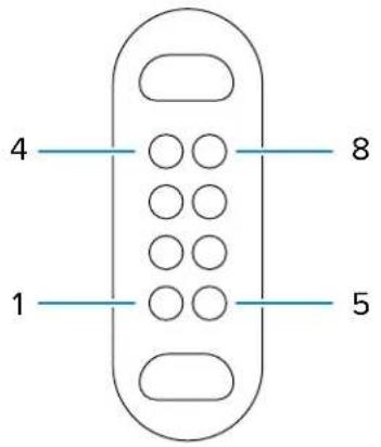
Table 24 I/O Connector Pin-Outs
| Pin Signal Description | |
| 1 GND Ground | |
| 2 D+ USB Data+ | |
| 3 VBUS/HOST 5 VDC Power Out | |
| 4 Trigger Scan Trigger | |
| 5 D- USB Data- | |
| 6 NC Not connected | |
| 7 DETECT Accessory presence detect | |
| 8 GND Ground |
Vehicle Dock Technical Specifications
This section provides specification information on the Vehicle Dock.
Table 25 Vehicle Dock Technical Specifications
| Feature Description | |
| Dimensions | Height: 19.2 cm (7.6 in.)Width: 28.8 cm (11.3 in.)Depth 8.2 cm (3.2 in.) |
| Weight 1.2 kg (2.6 lbs) | |
| Input Voltage 12-14 VDC | |
Technical Specifications
Table 25 Vehicle Dock Technical Specifications (Continued)
| Feature Description | |
| Maximum Power Consumption | 60 watts |
| Operating Temperature 0°C (32°F) to +50°C (+122°F) | |
| Storage Temperature -40°C (-40°F) to +70°C (+158°F) | |
| Charging Temperature 0°C to 40°C (32°F to 104°F) | |
| Humidity 5% to 95% non-condensing | |
| Drop 75 cm (30 in.) to concrete, 2 drops per side for a total 12 drops at room temperature 23°C (73.4°F). | |
| Electrostatic Discharge (ESD) | +/- 15 kV air+/- 8 kV contact |


- TERMS OF USE
- PROPRIETARY STATEMENT
- PRODUCT IMPROVEMENTS
- LIABILITY DISCLAIMER
- LIMITATION OF LIABILITY
- ABOUT THIS GUIDE
- NOTATIONAL CONVENTIONS
- ICON CONVENTIONS
- SERVICE INFORMATION
- GETTING STARTED
- UNPACKING THE DEVICE
- FEATURES
- NOTE
- SETTING UP THE DEVICE
- INSTALLING THE MICROSD CARD
- INSTALLING THE NANO SIM CARD
- REPLACING THE BATTERY
- DEVICE CHARGING
- CHARGING INDICATORS
- REPLACING THE MICROSD CARD
- REPLACING THE SIM CARD
- TURNING OFF THE DISPLAY
- TURNING OFF THE DEVICE
- USING THE DEVICE
- HOME SCREEN
- SETTING THE HOME SCREEN ROTATION
- STATUS BAR
- NOTIFICATION ICONS
- STATUS ICONS
- MANAGING NOTIFICATIONS
- OPENING THE QUICK ACCESS PANEL
- QUICK ACCESS PANEL ICONS
- BATTERY MANAGEMENT
- BATTERY TRUE HOT SWAP
- BATTERY TRUE HOT SWAP PERSISTENCE
- OTHER FACTORS AFFECTING BATTERY TRUE HOT SWAP BEHAVIOR
- TRUE HOT SWAP BATTERY REPLACEMENT
- BATTERY TRUE HOT SWAP RECOMMENDATIONS
- BATTERY-FREE OPERATION
- INTERACTIVE SENSOR TECHNOLOGY
- WAKING THE DEVICE
- USB COMMUNICATION
- TRANSFERRING FILES
- TRANSFERRING PHOTOS
- DISCONNECTING FROM THE HOST COMPUTER
- APPLICATIONS
- INSTALLED APPLICATIONS
- ACCESSING APPS
- SWITCHING BETWEEN RECENT APPS
- TOUCH RECENT
- BATTERY MANAGER
- OPENING BATTERY MANAGER
- BATTERY MANAGER INFORMATION TAB
- CAMERA
- TAKING PHOTOS
- RECORDING VIDEOS
- CAMERA SETTINGS
- QUICK SETTINGS
- OTHER SETTINGS
- STILL CAMERA
- VIDEO CAMERA
- SYSTEM
- DWDEMO
- DWDEMO ICONS
- SELECTING A SCANNER
- RXLOGGER
- RXLOGGER CONFIGURATION
- CONFIGURATION FILE
- ENABLING LOGGING
- DISABLING LOGGING
- EXTRACTING LOG FILES
- BACKING UP DATA
- RXLOGGER UTILITY
- PASS THROUGH ANTENNA SETTINGS
- CONFIGURING EXTERNAL ANTENNAS
- SET ANTENNA FOR DOCKED
- HEATER CONTROL
- STATUS
- TOUCH PANEL HEATER
- SETTINGS
- ACCESSING SETTINGS
- DISPLAY SETTINGS
- SETTING SCREEN BRIGHTNESS
- SETTING THE SCREEN BRIGHTNESS MANUALLY
- SETTING NIGHT LIGHT
- SETTING LOCK SCREEN NOTIFICATIONS
- SETTING DISPLAY AND TEXT SIZE
- NOTIFICATION LED BRIGHTNESS LEVEL
- SETTING TOUCH PANEL MODE
- SETTING THE DATE AND TIME
- GENERAL SOUND SETTING
- SOUND OPTIONS
- SETTING WAKE-UP SOURCES
- REMAPPING A BUTTON
- REMAPPABLE KEYS
- ON-SCREEN KEYBOARDS
- LANGUAGE USAGE
- CHANGING THE LANGUAGE SETTING
- ADDING WORDS TO THE DICTIONARY
- NOTIFICATIONS
- ENABLING BLINK LIGHT
- DATA CAPTURE
- IMAGING
- SCANNING CONSIDERATIONS
- SCANNING WITH THE INTERNAL SCANNER
- SCANNING WITH CAMERA
- SCANNING WITH THE RS5100 RING SCANNER
- PRESS AND HOLD THE TRIGGER
- SCANNING WITH THE RS6100 BLUETOOTH RING SCANNER
- SCANNING WITH THE DS3608 USB SCANNER
- SCANNING WITH THE DS3678 BLUETOOTH SCANNER
- SCANNING WITH THE LI3608 LINEAR SCANNER
- SCANNING WITH THE LI3678 LINEAR IMAGER
- PAIRING A BLUETOOTH RING SCANNER
- PAIRING USING SIMPLE SERIAL INTERFACE (SSI)
- PAIRING USING BLUETOOTH HUMAN INTERFACE DEVICE
- PAIRING IN SSI MODE USING NEAR FIELD COMMUNICATION
- PAIRING IN HID MODE USING NEAR FIELD COMMUNICATION
- PAIRING A BLUETOOTH SCANNER
- CONNECTING A USB SCANNER TO A DEVICE
- CONNECTING USING SIMPLE SERIAL INTERFACE
- CONNECTING USING HID MODE
- DATAWEDGE
- ENABLING DATAWEDGE
- DISABLING DATAWEDGE
- SUPPORTED DEVICES
- RS5100 SUPPORTED DECODERS
- RS6100 SUPPORTED DECODERS
- DS3608 SUPPORTED DECODERS
- DS3678 SUPPORTED DECODERS
- LI3608 SUPPORTED DECODERS
- LI3678 SUPPORTED DECODERS
- CAMERA SUPPORTED DECODERS
- WIRELESS
- WIRELESS WIDE AREA NETWORKS
- SHARING THE MOBILE DATA CONNECTION
- ENABLING USB TETHERING
- ENABLING BLUETOOTH TETHERING
- CONFIGURING THE WI-FI HOTSPOT
- ENABLING WI-FI HOTSPOT
- DATA USAGE
- SETTING DATA USAGE WARNING
- SETTING DATA LIMIT
- CELLULAR NETWORK SETTINGS
- DATA WHEN ROAMING
- ENABLING MMS MESSAGES
- SETTING PREFERRED NETWORK TYPE
- SETTING PREFERRED NETWORK
- CONFIGURING THE ACCESS POINT NAME
- LOCKING THE SIM CARD
- WIRELESS LOCAL AREA NETWORK
- CONNECTING TO A WI-FI NETWORK
- REMOVING A WI-FI NETWORK
- TOUCH FORGET
- WLAN CONFIGURATION
- CONFIGURING A SECURE WI-FI NETWORK
- MANUALLY ADDING A WI-FI NETWORK
- CONFIGURING FOR A PROXY SERVER
- CONFIGURING THE DEVICE TO USE A STATIC IP ADDRESS
- NETWORK PREFERENCES
- ADDITIONAL SETTINGS
- REGULATORY
- BAND AND CHANNEL SELECTION
- LOGGING
- ABOUT
- WI-FI DIRECT
- BLUETOOTH
- ADAPTIVE FREQUENCY HOPPING
- SECURITY
- BLUETOOTH PROFILES
- BLUETOOTH POWER STATES
- ENABLING BLUETOOTH
- DISABLING BLUETOOTH
- DISCOVERING BLUETOOTH DEVICE(S)
- CHANGING THE BLUETOOTH NAME
- CONNECTING TO A BLUETOOTH DEVICE
- SELECTING PROFILES ON THE BLUETOOTH DEVICE
- UNPAIRING A BLUETOOTH DEVICE
- CAST
- NEAR FIELD COMMUNICATIONS
- READING NFC CARDS
- ENTERPRISE NFC SETTINGS
- VEHICLE DOCK INSTALLATION
- MOUNTING SAFETY
- CAUTION
- ELECTRICAL GUIDELINES
- WARNING
- WIRING GUIDELINES
- MOUNTING THE VEHICLE DOCK
- INSTALLING THE KEYBOARD MOUNTING BRACKET
- ROUTING CABLES
- POWER
- INSTALLING A CLA CABLE
- NEW WIRED INSTALLATIONS
- VEHICLES WITH POWER 15 VDC OR LESS
- VEHICLES WITH POWER GREATER THAN 15 VDC
- MOUNTING THE DC/DC POWER SUPPLY
- NEW INSTALLATION WITH PS1370 POWER SUPPLY
- NEW INSTALLATION WITH 450083 OR 450084 POWER SUPPLY
- REPLACING LEGACY INSTALLATIONS
- REPLACING AN EXISTING LEGACY INSTALLATION WITH PS1370 POWER SUPPLY
- REPLACING AN EXISTING LEGACY INSTALLATION WITH 450083 OR 450084 POWER SUPPLY
- INSTALLING AN EXTERNAL ANTENNA
- INSTALLING THE SCREEN BLANKING CABLE
- INSTALLING THE KEYBOARD CABLE
- MOUNTING THE KEYBOARD
- INSTALLING A KEYBOARD ON A RAM MOUNT
- KEYBOARD HEATER
- ACCESSORIES
- CHARGING TEMPERATURE
- VEHICLE DOCK
- LED INDICATORS
- INSERTING THE TABLET INTO THE VEHICLE DOCK
- REMOVING THE TABLET FROM THE VEHICLE DOCK
- DESK STAND
- INSTALLING THE VEHICLE DOCK ON THE DESK STAND
- SETTING UP THE DESK STAND
- USB-C TO AC ADAPTER
- USB KEYBOARDS
- SOFT HANDLE
- ATTACHING THE SOFT HANDLE
- ATTACHING THE SHOULDER STRAP TO THE SOFT HANDLE
- REMOVING THE D-CLIPS
- SHOULDER STRAP
- ATTACHING THE SHOULDER STRAP
- STYLUS HOLDER
- INSTALLING THE STYLUS HOLDER
- APPLICATION DEPLOYMENT
- ANDROID SECURITY
- SECURE CERTIFICATES
- INSTALLING A SECURE CERTIFICATE
- ANDROID DEVELOPMENT TOOLS
- ANDROID DEVELOPMENT WORKSTATION
- ENABLING DEVELOPER OPTIONS
- EMDK FOR ANDROID
- SEE ALSO
- STAGENOW FOR ANDROID
- GMS RESTRICTED
- ADB USB SETUP
- ENABLING USB DEBUGGING
- ENTERING ANDROID RECOVERY MANUALLY
- APPLICATION INSTALLATION METHODS
- INSTALLING APPLICATIONS USING THE USB CONNECTION
- INSTALLING APPLICATIONS USING THE ANDROID DEBUG BRIDGE
- INSTALLING APPLICATIONS USING A MICROSD CARD
- UNINSTALLING AN APPLICATION
- ANDROID SYSTEM UPDATE
- PERFORMING A SYSTEM UPDATE USING A MICROSD CARD
- PERFORMING A SYSTEM UPDATE USING ADB
- PRESS ENTER
- VERIFYING SYSTEM UPDATE INSTALLATION
- ANDROID ENTERPRISE RESET
- PERFORMING AN ENTERPRISE RESET FROM DEVICE SETTINGS
- PERFORMING AN ENTERPRISE RESET USING A MICROSD CARD
- PERFORMING AN ENTERPRISE RESET USING ADB
- ANDROID FACTORY RESET
- PERFORMING A FACTORY RESET USING MICROSD CARD
- PERFORMING A FACTORY RESET USING ADB
- ANDROID STORAGE
- RANDOM ACCESS MEMORY
- VIEWING MEMORY
- INTERNAL STORAGE
- VIEWING INTERNAL STORAGE
- ENTERPRISE FOLDER
- EXTERNAL STORAGE
- VIEWING EXTERNAL STORAGE
- FORMATTING A MICROSD CARD AS PORTABLE STORAGE
- FORMATTING A MICROSD CARD AS INTERNAL MEMORY
- MANAGING APPS
- APP DETAILS
- MANAGING DOWNLOADS
- MAINTENANCE AND TROUBLESHOOTING
- MAINTAINING THE DEVICE
- BATTERY SAFETY GUIDELINES
- BEST PRACTICES FOR ENTERPRISE MOBILE COMPUTING DEVICES OPERATING IN HOT ENVIRONMENTS AND DIRECT SUNLIGHT
- APPROVED CLEANING AND DISINFECTANT AGENTS
- IMPORTANT
- CLEANING INSTRUCTIONS
- APPROVED CLEANSER ACTIVE INGREDIENTS
- HARMFUL INGREDIENTS
- SPECIAL CLEANING NOTES
- CLEANING FREQUENCY
- DEVICE CLEANING INSTRUCTIONS
- DISPLAY
- HOUSING
- CAMERA AND EXIT WINDOW
- CLEANING CRADLE CONNECTORS
- TROUBLESHOOTING
- RESETTING THE DEVICE
- PERFORMING A SOFT RESET
- PERFORMING A HARD RESET
- TROUBLESHOOTING THE DEVICE
- TECHNICAL SPECIFICATIONS
- SE55 DECODE DISTANCES
- I/O CONNECTOR PIN-OUTS
- VEHICLE DOCK TECHNICAL SPECIFICATIONS
Brand : Xplore
Model : ET65
Category : Tablet