
EVO270-E - Water heater EvoHeat - Free user manual and instructions
Find the device manual for free EVO270-E EvoHeat in PDF.


| Product Type | Hot Water Heat Pump |
| Model | EVO270-E |
| Storage Capacity | 270 L |
| Rated Outlet Water Temperature | 60 °C |
| Heating Capacity | 4.0 kW |
| Heating Power Input | 0.85 kW |
| Rated Power Input | 2.38 kW |
| COP at 20 °C Air | 4.7 |
| Noise Rating | 46 dB(A) |
| Running Current | 3.6 A |
| Rated Current Input | 9.9 A |
| Power Supply | 220-240 V ~ 50 Hz |
| Water Inlet/Outlet Size | 3/4 inch BSP |
| Auxiliary Heating (Electric Element) | 1.0 kW |
| Net Weight | 114 kg |
| Moisture Resistance | IPX4 |
| Electrical Shock Protection | Class I |
| Refrigerant | R290 / 480 g |
| Compressor Type | Rotary |
| Dimensions (Height x Diameter) | 2010 mm x 640 mm |
| Operating Ambient Temperature Range | -5 °C to 43 °C |
| Maximum Water Outlet Temperature | 75 °C |
| Operating Modes | Heating, Eco Heating, Intelligent, High Requirement, Vacation |
| Controller | Digital touch/button with lock, timer, Hydroboost, defrost, Sanitech, fan control |
| Recommended Maintenance | Annual minor check; professional 3-year service |
Frequently Asked Questions - EVO270-E EvoHeat
User questions about EVO270-E EvoHeat
0 question about this device. Answer the ones you know or ask your own.
Ask a new question about this device
Download the instructions for your Water heater in PDF format for free! Find your manual EVO270-E - EvoHeat and take your electronic device back in hand. On this page are published all the documents necessary for the use of your device. EVO270-E by EvoHeat.
USER MANUAL EVO270-E EvoHeat
EVO270-E
HOT WATER HEAT PUMP

Contents
- Introduction......2
- Dimensions....2
- Quick Start Guide....3
- Safety Instructions....4
- Installation 5
5.1 System Installation 5
5.2 Handing & Transportation .... 5
5.3 Location of Installation 5
5.4 Airflow Clearances 6
5.5 Cable Connection....6
5.6 Filling the Tank....6
5.7 Initial Start-Up 6
- Operation....7
6.1 The Controller 7
6.2 Operating Functions....8
6.2.1 Locking the Controller 8
6.2.2 Startup & Shutdown 8
6.2.3 Switching Modes 8
6.2.4 Setting & Checking the Target Temperature 9
6.2.5 Hydroboost Setting....9
6.2.6 Force Defrost....9
6.2.7 System Date & Time 10
6.2.8 Setting & Cancelling Timers....10
6.2.9 Vacation Mode 11
6.2.10 Sanitech System 12
6.2.11 Fan/Ventilation Function 12
This manual contains information relating to the installation, troubleshooting, operation, and maintenance of this EvoHeat unit. Instructions in this manual must always be followed. Failure to comply with these recommendations will invalidate the warranty. Should you have any questions or require technical support, call the EvoHeat office on 1300 859 933 to speak to our team.
| TECHNICAL DATA | EVO270-E | |
| Storage Capacity L 270 | ||
| Rated Outlet Water Temp. | °C | 60 |
| Heating Capacity | kW | 4.0 |
| Heating Power Input | kW | 0.85 |
| Rated Power Input | kW | 2.38 |
| C.O.P at 20°C Air | 4.7 | |
| Noise Rating | dB(A) | 46 |
| Running Current | A | 3.6 |
| Rated Current Input | A | 9.9 |
| Power Supply | 220-240V~50Hz | |
| Water Inlet/Outlet Size | inch | 3/4" |
| Auxiliary Heating | kW | 1.0 |
| Net Weight | kg | 114 |
| Moisture Resistance | IPX | IPX4 |
| Electrical Shock Proof | I | I |
| Refrigerant | G | R290 / 480g |
| Compressor | Rotary | |

The EVO270-E is the next evolution in water heating with advanced energy efficiency technologies and built-in smart features to ensure you're provided with clean, safe, and economical hot water all year round.
Conforms to AS 3498-2020 Australia and New Zealand
Measurement conditions: Instant heating:
• Ambient air temperature: 20°C/15°C
• Water inlet: 15°C
• water outlet: 55°C
• highest setting temperature: 75°C
2. Dimensions


| EVO270-E | unit: mm |
| A (HEIGHT) | 2010 |
| B | 1451 |
| C | 1211 |
| D | 1111 |
| E | 115 |
| F (DIAMETER) | 640 |

DO NOT DRILL
Do not drill any fixings or attachments into the outer casing of the tank. Drilling into the outer casing of the tank may damage the heating coil and WILL VOID WARRANTY.
INITIAL STARTUP
-
Press and hold 🤊 for one second to power on the unit.
-
To set the time:
a. Press once so the hour digit starts flashing,
b. Use ▲ √ to adjust the hour and press Ⓛ to confirm,
c. Repeat for the minute, day, month and year,
d. Press ⏻ at any stage to cancel.
-
Press 📁 until 🌿 is displayed. This will activate “Eco Heating” (Heat Pump only) mode and will provide the most efficient heating.
-
During periods of unusually high hot water demand (such as additional occupants staying with you), you can activate "High Requirement" mode by pressing until is displayed.
-
In any event where there is a failure within the system, the Electric Element (Hydroboost Mode) can be engaged with "one push activation" of the button until is displayed. This will provide emergency water heating until service can be attended.
-
For adjustment of timers or activating vacation mode, please refer to our online tutorials at: www.evoheat.com.au/tech-support
4. Safety Instructions
Ensure that all safety instructions and recommendations are always adhered to. Failure to comply with these recommendations could void the warranty and cause injury or death. Always use a suitably qualified Electrician to perform any electrical work, they must read the manual before connecting.

Ensure all cabling, circuit breakers, and protections are of a suitable size and specification in accordance with electrical wiring legislation for the heater being installed. Ensure to check that there is adequate voltage and current available at the heater connection to run the unit.
General Compliance:
- Adhere to all safety instructions and recommendations to avoid voiding the warranty and risk of injury or death.
- Installation, repair, service or relocation must be performed only by qualified technicians, in line with Australian Standards and Industry Codes, including electrical safety, plumbing, and heat pump installation.
- The unit must be installed to conform to all relevant Australian Standards and Industry Codes including but not limited to: Electrical & Electrical Safety, Plumbing & Hot Water Storage, Heat Pump Installation & Operation.
- Installation must also comply with any local, state or federal codes at the installation site. Failure to comply can void your warranty, damage your unit, or possibly cause injury or death. Plumbing must comply with AS/NZS3500.4.
Electrical & Installation Safety:
• Install a circuit breaker for the unit.
- Ensure good power connection and earthing.
- Disconnect all supply circuits before accessing terminals.
- Use a qualified electrician for electrical work, ensuring cabling, circuit breakers, and protections are suitable.
- Avoid leaks in plumbing and drainage fittings.
- Do not install near flammable gases or aerosols.
- Ensure a level, stable base.
- Comply with national wiring regulations and local codes.
- Keep the area around the unit dry, clean, and well-ventilated for optimal heat transfer and energy efficiency.
Operational Safety & Maintenance:
- A Pressure & Temperature (P&T) valve must be installed in the tank. When the tank pressure reaches 0.85MPa or when the tank temperature reaches 99°C, the P&T valve will open automatically to reduce the pressure or temperature.
- Use the unit within the environmental temperature range of -5°C to 43°C .
- Install temperature and pressure protective equipment as required by local codes, including a temperature and pressure relief valve certified to ANSIZ21.22 standards.
-
Avoid using unsafe water sources such as lake or groundwater.
-
Be cautious of hot fittings.
- Observe a 3-minute delay when manually restarting the unit.
- Test the P&T valve biannually for blockages.
- Use a 5A/250VAC safety cable meeting explosion-proof requirements.
- Secure all connections before powering on.
- The installer must explain operation and maintenance to the end user.
- For systems unused for over two weeks, open a hot water faucet for several minutes before using any electrical appliance to prevent flammable hydrogen gas build-up.
- In the event of the unit malfunctioning, shut off the power supply and contact your supplier or EvoHeat.
- Do not drill any fixings or attachments into the outer casing of the tank. Drilling into the outer casing of the tank may damage the heating coil and WILL VOID WARRANTY.
Additional Precautions:
- Evo Industries Australia Pty Ltd is not responsible for damages or injuries due to incorrect installation.
- Follow the recommended maintenance programme in the manual.
- The appliance should have disconnection means with contact separation in all poles for full disconnection under overvoltage category III conditions, in accordance with wiring rules.

WARNING
THIS PRODUCT CONTAINS A BUTTON BATTERY
If swallowed, a lithium button battery can cause severe or fatal injuries within 2 hours.
Keep batteries out of reach of children.
If you think batteries may have been swallowed or placed inside any part of the body, seek immediate medical attention.
5. Installation
5.1 System Installation
Upon receiving the unit, check the packaging for any obvious signs of damage. Inform EvoHeat immediately if there is any evidence of rough handling.

Do not drill any fixings or attachments into the outer casing of the tank. Drilling into the outer casing of the tank may damage the heating coil and WILL VOID WARRANTY.

The P&T valve attached with the unit must be installed. Failure to do so will cause damage to the unit and possible personal injury.

Drain the water tank through the drain valve at the bottom part of the unit.

Do not use stainless steel fittings to connect directly with other metals to prevent galvanic corrosion.
![graph TD A["Tap Water"] --> B["Y-Shaped Filter"] B --> C["Water Inlet"] C --> D["Magnesium"] D --> E["Condensate Outlet"] E --> F["P&T Valve"] F --> G["Drainpipe"] G --> H["Water Outlet"] H --> I["Water Inlet"] I --> J["Condensate Outlet"]](/content/2026/05/958562/images/fc791890217d91f1473dbd3824c3b6c55d79aa156ce54a8003888c2ac7ea70da.jpg)
A pressure releasing valve is to be fitted within the installation. Spec of P&T valve: Pressure: 0.85MP Temperature: 99°C

- Use BSP3/4 internal thread pipes for water inlet and outlet, ensuring they are heat-resistant and durable.
- The P&T valve should also use a BSP3/4 internal thread. Ensure its drainpipe outlet is exposed to air and the flexible drainpipe points downwards.
5.2 Handing & Transportation
The unit should be stored and transported in an upright position, without water, and is allowed a maximum tilt of 30 degrees for short distances. Keep it within ambient temperatures of 0° C to 40° C. For forklift transportation, the unit must remain on its pallet, be lifted slowly, and be secured to prevent tipping over.

When manually transporting, use the wooden pallet and ropes or straps, ensuring the unit doesn't exceed a 60-degree tilt. After any inclined transport, let the unit rest for an hour before operation.
5.3 Location of Installation
The heat pump is designed for external installation, however, where possible installing the unit under the house eaves or in a sheltered environment may help prolong the life of the system.
Heat pumps operate most efficiently with warmer air temperatures, and the outlet air from the unit will always be colder than the inlet air. Therefore, it is advisable to install the unit, so it receives the warmest air temperatures possible and that the cold air is not able to recirculate back into the unit.
5.4 Airflow Clearances

The unit must be installed with sufficient clearances to allow airflow to circulate through the unit, it is advised to keep a minimum gap between walls/fences etc of:
• Air Inlet/Outlet Sides: 1000mm
• Overhead Clearance: 600mm
• Rear Clearance: 300mm
Without sufficient airflow, discharged cold air will recirculate into the unit and consequently lower the heating efficiency or cause potential compressor failure.
If the installation location does not comply with these suggested clearances, contact EvoHeat's Technical Support to discuss possible solutions.
Non-compliant installations risk voiding the warranty; ensure adherence to AS/NZS 3500.4
5.5 Cable Connection
The power cable for power supply of the unit is stored in the back of the unit. The unit must be installed in accordance with Australian standards. If the power cord is damaged, it must be replaced by a qualified electrician. Wi-Fi cable connection/plug should be protected from weather and potential water ingress using the supplied heat shrink.
5.6 Filling the Tank
Open a hot water tap inside the house. Open the cold-water inlet valve into the unit to fill the tank. When water begins flowing out of the hot water tap inside the premises, turn off the hot water tap.
5.7 Initial Start-Up
PRE-INSPECTION
Check the water supply to the tank and pipe connections for possible leaks.
Check that the following devices are installed and operating correctly:
- Drainpipes
- P&T Valve
- Filter on inlet
• Water softening and pressure reducing devices if required.
Check that all power connections are secure before switching on.
Check that the installation space is adequate.
TRIAL OPERATION
Switch on the unit by using the controller.
If any unusual noises occur, switch the power off and consult your provider.
The parameters have been pre-set to a temperature of 60 degrees. Check that the unit is operating by looking for an increase in water temperature over time.
6. Operation
6.1 The Controller

 | ON/OFF | Turn the unit on or off. |
 | UP | Select options to increase values |
 | DOWN | Select options to decrease values |
 | CLOCK | Set the clock or the timer. |
 | HYDROBOOST | Turn on/off the electric heater |
 | MODE | Switch unit running modes or save setting parameters |
 | TOUCH TIMING | Touch timing settings |


SET
HEATING MODE
The unit primarily uses the heat pump based on water and target temperatures. If the target is not reached within 200 minutes, the electric heater activates to assist.
ECO HEATING MODE
Prioritises energy efficiency by utilising only the heat pump. The electric heater is never engaged, promoting lower energy use. EvoHeat recommend using this mode as standard.
INTELLIGENT MODE
The unit will automatically judge the operation mode according to the ambient temperature.
HIGH REQUIREMENT MODE
Operates similarly to Heating Mode but with an immediate start of the electric heater, providing quick water heating when fast temperature rise is needed.
VACATION MODE
Enable Vacation mode
FAN
Fan is on
HYDROBOOST
The Hydroboost setting is on
DEFROST
The unit is defrosting
LOCK
Keyboard is locked
PARAMETER SETTING
Parameter is adjustable

min

SET TEMP REACHED
Set temperature has been reached and the unit will shut off automatically
LOWER TANK TEMP
Temperature of the lower tank
MINUTE
Minute value is being set
SECOND
Second value is being set
WI-FI
State of Wi-Fi connection *Only available as an optional upgrade
6.2 Operating Functions
EvoHeat have developed a YouTube Channel with video walkthroughs of the different controller functions.
Scan the QR code or head to our channel to view the video s we have available https://www.youtube.com/@evoheatpumps

6.2.1 Locking the Controller
To both lock and unlock the controller, press and hold the ⏻ button for 5 seconds.
When the controller is locked, a lock symbol will appear on the bottom right.
6.2.2 Startup & Shutdown
Press ⏻ and hold for 0.5 seconds in the standby screen of the controller to turn the unit on. The main display will now show the water outlet temperature.
Press 🔊 and hold for 0.5 seconds in the running screen of the controller to turn the unit off. The main display will now show "OFF".
The unit will dim the screen and display the standby screen when the controller has not been touched for a minute. Touch the power button to wake it.
Note: The ON/OFF button can only be used to turn the unit on/off in standby or on the running screen of the controller.

6.2.3 Switching Modes

We recommend running the unit in Eco Heating mode where possible for maximum energy efficiency.
From the running screen, press 📋 to select one of the modes: Heating, Eco Heating, Intelligent, High requirement, Vacation.

Press 📄 to alternate between different modes.
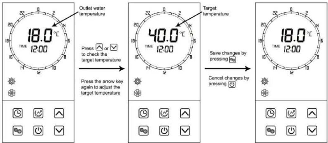
6.2.4 Setting & Checking the Target Temperature
In the standby or running interface, press ▲ or ▼ once to check the target temperature of the outlet water.
Press ▲ or ▼ again to change the target temperature.
After making changes to the desired temperature, press 🔒 to confirm or ⏻ to cancel, then return to the previous screen.
If the keypad is left idle for 5 seconds, the controller will exit the menu automatically and apply any changes that were made.
Example: The target temperature is 40°C, the actual outlet water temperature is 18°C.
6.2.5 Hydroboost Setting

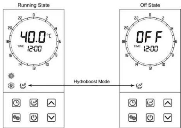
Also known as the Electric heater, the Hydroboost setting allows higher levels of hot water to be produced. When there are high hot water usage requirements (such as guests staying), this function may come in useful.
The Hydroboost setting can be turned on when the unit is in heating or in standby mode.
Press ☐ once to turn on Hydroboost on or off.
When activated, will light up on the main display.
6.2.6 Force Defrost

In the extremely unlikely circumstance of the unit icing up (for example, if the unit was installed inside with no ventilation), this function can be applied.
When the unit is off, press and hold ⏻ for 10 seconds to enable the forced defrosting function. The defrosting symbol will light up. Press ⏻ for 10 seconds again to exit the forced defrosting function.
6.2.7 System Date & Time
In the standby or running interface, press ⏻ once, the hour digit will flash indicating it is being altered. Press the ∧ or √ to change the hour setting, then press ⏻ to confirm. Repeat this to change the minute value.
![graph TD A["40.0°C TIME 12:00"] -->|Press then press or to change the hour| B["40.0°C TIME 11:00"] B -->|Press or to change the minute| C["40.0°C TIME 11:30"] C -->|Then press to confirm| D["40.0°C TIME 08:04"] D -->|Press then press or to change the month| E["40.0°C TIME 07:05"] E -->|Press or to c…](/content/2026/05/958562/images/356ac1d2ed87c49c98d6e7ab24a99fb1450a606ac3a465fee13383dd5652c920.jpg)
6.2.8 Setting & Cancelling Timers
Timers can be set in standard mode, economic mode, auto mode & fast heating mode. They can be set by using buttons or using the touch timing circle. The unit will run during the lit time periods and stop in the dim areas.
Touch Method Button Method
- Press ⏻ and hold for 2 seconds (the timer display will flash)
- When the timer display flashes, choose your start-up time (A) and end time (B).
-
Press 📁 to save the setting and exit back to the main interface.
-
Press 📊 and hold for 2 seconds (the timer display will flash)
- When the timer display flashes, choose the start-up time (C) and end time (D) by pressing ▲ or ▼ and Ⓤ.
- Press ☐ to save the setting and exit back to the main interface.
Example: Setting the unit to run from 7-11am & 4pm-6pm using Touch mode.
![graph TD A["40.0°C TIME 12:00"] -->|Press Cell 8, it will begin to flash| B["40.0°C TIME 12:00"] B -->|Press Cell 18, it will light grid 8-18.| C["40.0°C TIME 12:00"] C --> D["Press Cell 12, it will begin to flash"] D -->|Press Cell 16, 12-16 will become dim (timer is off during this period)| E["40.…](/content/2026/05/958562/images/f7be1644ac580338cc156dacbafb790619f3925b27744b773c5dfb4ab8c22bc9.jpg)
To cancel a timer once it has been set, hold down the CLOCK Ⓤ button for 2 seconds until the timer display begins flashing (as you would set the timer).
Press the POWER ⏻ button while the timer is flashing to cancel it. The yellow timing periods will disappear when the timer has been cancelled.
6.2.9 Vacation Mode

Vacation Mode allows you to turn the unit off to conserve power for an extended period of time, and restart operation on a date you specify. This ensures you have hot water waiting for you upon your return.
Ensure the unit is 'OFF' before setting vacation mode. The date you set in this mode will determine what date the unit starts back up.
After selecting vacation mode, press and hold 📊 for 2 seconds, the 'month' value will begin to flash in the display area. Press the UP or DOWN arrows to display the desired month, then press 🔒 to confirm and move to altering the 'day' value.
The 'day' value will flash when it is selected, use the arrow keys to select your desired start day, then press 🔒 to save all changes and exit back to the main interface.
Note: Format is mm/dd
Example: The unit will start up on September the 28 th .
![graph LR A["OFF 06:20"] --> B["Use ▲ or ✓ to change month"] B --> C["Press to save and alter day"] C --> D["OFF 09:20"] D --> E["Use ▲ or ✓ to change day"] E --> F["Press to save all changes"]](/content/2026/05/958562/images/49be31aaa917791897614405de3f3c9eb9587b113eb7d1b1d8e0bfbf1dd8636a.jpg)
6.2.10 Sanitech System
The Sanitech feature's purpose is to keep the water free of bacteria such as Legionella by heating the tank water to 60°C each day at midday.

An instance when you may want to alter the Sanitech function is if you have solar power and would prefer the Sanitech to run during the day, for example, at a specific time to maximise solar energy use.
If you would like to change this function, contact EvoHeat's service department for guidance. Incorrectly attempting to adjust these settings yourself could significantly disrupt the unit's operation.
6.2.11 Fan/Ventilation Function

This function may come in useful if the system is installed inside and the fan settings need to be adjusted to suit ducting or external ventilation. This function allows you to set the fan speed as Off, Low Speed or High Speed.
If you would like to change this function, contact EvoHeat's service department for guidance. Incorrectly attempting to adjust these settings yourself could significantly disrupt the unit's operation.
7. Troubleshooting
7.1 Troubleshooting Q & A
Why does the compressor not run immediately when I start up the unit?
- After the unit is powered on, following a shutdown, there is a built-in delay of 3 minutes before the compressor starts running. This delay is a self-protection feature of the unit, designed to prevent damage and ensure the system's longevity.
Why does the outlet water temperature on the display sometimes increase slowly?
- Initially, there is a variation in water temperature between the upper and lower layers of the tank. As the heating process begins, the temperature in different parts of the tank equalizes, which initially causes a slower rise in temperature. Once the temperature becomes more uniform throughout the tank, the increase on the display will be faster.
Why does the outlet water temperature on the display decrease when the unit is in heating mode?
- If there is a significant temperature difference between the upper (hotter) water and the bottom (colder) water in the tank, the water temperature may decrease slightly due to convection currents. These currents occur as hot water rises and cold water sinks, leading to a temporary mixing and a slight decrease in temperature.
Why does the unit not start heating immediately when the outlet water temperature decreases?
- The unit is designed to avoid frequent on/off cycling, which can occur due to minor temperature fluctuations. If the hot water in the tank is not used for an extended period, the temperature may naturally decrease due to heat loss. To prevent unnecessary cycling, the unit is programmed not to start heating again until the water temperature decreases by more than 5 degrees. This feature helps in conserving energy and extending the life of the unit.
Why does the outlet water temperature decrease abruptly?
- The decrease in outlet water temperature occurs due to the mixing of hot and cold water within the tank. When the hot water at the top of the tank is depleted, cold water from the bottom can reach the upper sensor, resulting in a sudden temperature drop.
Why is hot water still available when the display shows a significant decrease in the outlet water temperature?
- This happens because the upper sensor is located near the top of the tank. Even when the display indicates a significant decrease in outlet water temperature, approximately one-fifth of the tank's capacity for hot water remains available.
Why does the compressor stop while the fan continues to run in heating mode?
- In heating mode, the unit may need to defrost if the evaporator freezes due to low ambient temperatures. During this defrosting process, the compressor will stop operating, but the fan will continue to run to facilitate defrosting.
Why does the heating process take the time it does?
- The unit is engineered for optimal energy efficiency, which means it operates with lower power consumption and thus, a standard heating duration that aligns with typical heat pump performance. The usual heating time ranges between 2 to 6 hours, depending on factors such as the initial temperature of the water, the volume of water usage, and the surrounding environmental temperature. This duration is standard for heat pumps and reflects the balance between energy efficiency and effective heating performance.
7.2 Error Codes
| Error | Reason | Elimination Methods |
| P01 | Bottom Water Temperature Sensor Failure (open or short circuit) | Inspect or replace the bottom water temperature sensor. |
| P02 | Top Tank Water Temperature Sensor Failure (open or short circuit) | Inspect or replace the top tank water temperature sensor. |
| P03 | Discharge Temperature Sensor Failure (open or short circuit) | Inspect or replace the discharge temperature sensor. |
| P04 | Ambient Temperature Sensor Failure (open or short circuit) | Inspect or replace the ambient temperature sensor. |
| P05 | Coil Temperature Sensor Failure (open or short circuit) | Inspect or replace the coil temperature sensor. |
| P07 | Suction Temperature Sensor Failure (open or short circuit) | Inspect or replace the suction temperature sensor. |
| P08 | Solar Temperature Sensor Failure (open or short circuit) | Inspect or replace the solar temperature sensor. |
| P82 | Discharge Overheating Protection | Check for leaks or blockages in the refrigerant system. |
| E01 | High Pressure Protection (Excessive exhaust pressure, high pressure switch activated) | Inspect the high-pressure switch and check for blockages in the refrigerant system. |
| E02 | Low Pressure Protection (Reduced suction pressure, low pressure switch activated) | Inspect the low-pressure switch and check for leaks in the refrigerant system. |
| E08 | Communication Failure (Issue with wired remote control signal) | Check the connection between the wired remote control and the motherboard. |
| E09 | Winter Frost Protection | The water temperature is too low - ensure anti-freezing measures are in place. |
| E11 | DC Motor Stalling | Inspect the motor and its connection. |
| E13 | Electronic Anode 1 Short-Circuit | Check the electronic anode and its connection to the main controller. |
| E14 | Electronic Anode 1 Open-Circuit | Check the electronic anode and its connection to the main controller. |
| E18 | Electronic Anode 2 Short-Circuit | Check the electronic anode and its connection to the main controller. |
| E19 | Electronic Anode 2 Open-Circuit | Check the electronic anode and its connection to the main controller. |
| E43 | High Pressure Switch Triggered Thrice | Inspect the high pressure switch and check for blockages in the refrigerant system. |
| E44 | Low Pressure Switch Triggered Thrice | Inspect the low pressure switch and check for leaks in the refrigerant system. |
| E45 | Discharge Overheating Triggered Thrice | Check for leaks or blockages in the refrigerant system. |
8. Appendix
8.1 Wiring Diagram
![graph TD A["AT: Ambient temperature"] --> B["BM"] C["BTT: Bottom of tank temperature"] --> D["COMP: Compressor"] E["CT: Coil temperature"] --> F["E2V: Electromagnetic 2 way valve"] G["EEV: Electronic expand valve"] --> H["ET: Exhaust temperature"] I["FM: Fan motor"] --> J["HP: High pressure protecti…](/content/2026/05/958562/images/dfd8d4ba699cca5a7c8b0ab32a7cc24287a83b01f5d7508913df3752de072e35.jpg)
8.2 Use of the P&T Valve

WARNING: Failing to operate the relief valve easing gear at least once every six months may result in the water heater exploding. Continuous leakage of water from the valve may indicate a problem with the water heater.

The Pressure and Temperature (P&T) valve is crucial for maintaining safe levels inside the tank. It automatically opens to release water if either the temperature or pressure exceeds the predetermined settings, preventing dangerous build-ups.
Maintenance of Safety Valve: Test the safety valve handle every six months to clear out calcium carbonate deposits and ensure the valve is unblocked. Be cautious of the high temperature of the discharged water to avoid burns. Additionally, keep vent pipes thermally insulated to prevent them from freezing in winter, which can pose safety risks.
Valve Replacement: If replacement of the P&T valve is necessary, it should match the original in performance, size, and specifications.
8.3 Using the Overheating Protector
The overheating protector is designed to turn off the power during emergencies or power issues, ensuring the water doesn't overheat.
In the event of a thermal cut-out, consider it a potential safety hazard. It's crucial to have the unit serviced by a qualified technician before attempting a reset. Contact EvoHeat for service in such cases.
To return the unit to its normal operation status by resetting manually:
a) To access the overheat protector, remove the front dark grey controller panel.
b) Remove the 3 screws on the front panel and push the front cover upwards.
c) Remove the remaining screws which cover the overheat protector panel.

Remove the screws and open the cover

Press the red button to reset
8.4 Draining the Water Tank

The water from the hot water tap and the drain plug will be hot. Be careful of burns and scalds. Wear protective clothing.
- Close the cold-water inlet valve into the EVO270-E.
- Open a hot water tap inside the premises.
- Undo the drain plug on the base of the unit to drain the water from the system.
8.5 Wi-Fi Module Connection (Optional)
Note: If you do not have a Wi-Fi module to install, apply heat shrink to the plug, this will protect it from water ingress.
The optional Wi-fi Control upgrade can be purchased to allow you to remotely control your EvoHeat hot water heat pump from your phone.
Newly installed units will have a small cable protruding from behind the top panel covered in heat shrink.
If you are installing the Wi-Fi module, simply connect the cable of the Wi-Fi module to the one that protrudes.
Once the Wi-Fi module has been connected, ensure that the connection plug has the heat shrink applied to the plug and the cable is protected from water and dust.
The module must be placed with the cord facing downwards to protect it from water tracking.

9. Maintenance
9.1 Maintenance Periods
Your EVO270-E will operate most efficiently if regularly inspected as part of your home maintenance schedule.
ANNUAL MAINTENANCE
It is recommended that the minor maintenance be performed every 12 months by the dwelling occupant.
The minor maintenance includes:
- Operate the easing lever on the temperature pressure relief valve. It is very important you raise and lower the lever gently. Exercise care to avoid any splashing of water, as water discharged from the drain line will be hot. Stand clear of the drain lines point of discharge when operating the valve's lever.
- Operate the easing level on the expansion control valve (if fitted). It is very important you raise and lower the lever gently.
- Conduct a visual inspection of all plumbing and electrical connections.
- Check the condensate drain line to ensure it is not blocked.
- Check that air vents and evaporator is not blocked or obstructed, and if necessary, isolate the power to the system and clear with a brush.
- Conduct a general external clean of the unit with a damp cloth.
THREE-YEAR SERVICE

It is a warranty requirement that a three (3) year service must be conducted on the EVO270-E.
Just as a car needs regular servicing, your heat pump also requires a three-year service to maintain efficiency and ensure long-term performance.

Warning: Servicing of a water heater must only be carried out by qualified EvoHeat personnel. Phone EvoHeat Service on 1300 859 933 for our closest Accredited Service Agent.
Note: The three-year service and routine replacement of any components such as the anode and relief valve(s) are not included in the EvoHeat warranty. Only genuine replacement parts should be used on this water heater.
The service includes the following actions:
- Replace the temperature limiting valve.
- Replace the temperature pressure relief valve.
- Inspect the anode and if required, replace the anode. If the anode is not replaced, it should be replaced within three years of this service.
- Check the heating cycle of the unit.
- Visually check the unit for any potential problems.
- Inspect the plumbing and electrical all connections.
- Check the condensate on drain line to ensure it is not blocked.
Note: The water heater may need to be drained during this service. After the completion of the service, the water heater will take some time to reheat the water. Depending upon the power supply connect on, hot water may not be available until the next day.
10. Warranty

Refer to the EvoHeat website for warranty details
Australia: https://evoheat.com.au/warranty-terms/
South East Asia: http://evoheat.com.sg/warranty/
REGISTER YOUR WARRANTY

EvoHeat highly recommend customers complete their warranty details online to ensure efficient warranty claim processing. To register your warranty, scan our QR Code or head to our website and fill in the Warranty Registration Form: https://evoheat.com.au/warranty-registration/
-
Warranty terms are from date of purchase.
-
This warranty excludes any defect or injury caused by or resulting from misuse, abuse, neglect, accidental damage, improper voltage, vermin infestation, incompetent installation, any fault not attributable to faulty manufacture or parts, any modifications which affect the reliability or performance of the unit.
-
This warranty does not cover the following:
a) Natural Disasters (hail, lightening, flood, fire etc.)
b) Damage resulting from any animal or creature (including vermin, reptiles and insects)
c) Rust or damage to exterior coatings, materials, and cabinet caused by corrosive atmosphere or weather/environmental conditions.
d) When serviced by an unauthorised person without the permission of Evo Industries.
e) When a unit is installed by an unqualified person.
f) When failure occurs due to improper or incorrect installation.
g) Where failure occurs due to failure of any other equipment connected in relation with the EvoHeat unit (e.g. power supply, water pump etc.).
h) Where failure occurs due to improper maintenance or misuse (refer Operating Instructions).
i) Where the unit has not had its three-year general maintenance service performed by a certified plumber. Proof of this service will be required for warranty claims beyond three years.
j) 'No Fault Found' service calls where the perceived problem is explained within the operation instructions.
k) Costs associated with delivery, handling, freighting, or damage to the product in transit.
I) Where the unit has been relocated from its originally installed location.
- If warranty service is required, you should:
a) Contact Evo Industries Australia on 1300 859 933 or via our Contact page on our website.
b) Provide a copy of your receipt as proof of purchase.
c) Have completed the online Service Request Form via the website www.evoheat.com.au/service-request/
-
Onsite technical service is available within the normal operating area of your Evo Authorised Service Agents. Service outside this area will incur a traveling fee.
-
Unless otherwise specified to the purchaser, the benefits conferred by this express warranty and additional to all other conditions, warranties, rights and remedies expressed or implied by the Trade Practices Act 1974 and similar consumer protection provisions contained in legislation of the States and Territories and all other obligations and liabilities on the part of the manufacturer or supplier and nothing contained herein shall restrict or modify such rights, remedies, obligations or liabilities.
- EVO270-E
- CONTENTS
- CONFORMS TO AS 3498-2020 AUSTRALIA AND NEW ZEALAND
- MEASUREMENT CONDITIONS: INSTANT HEATING
- DIMENSIONS
- DO NOT DRILL
- INITIAL STARTUP
- SAFETY INSTRUCTIONS
- GENERAL COMPLIANCE
- ELECTRICAL & INSTALLATION SAFETY
- OPERATIONAL SAFETY & MAINTENANCE
- ADDITIONAL PRECAUTIONS
- WARNING
- THIS PRODUCT CONTAINS A BUTTON BATTERY
- INSTALLATION
- 5.1 SYSTEM INSTALLATION
- 5.2 HANDING & TRANSPORTATION
- 5.3 LOCATION OF INSTALLATION
- 5.4 AIRFLOW CLEARANCES
- 5.5 CABLE CONNECTION
- 5.6 FILLING THE TANK
- 5.7 INITIAL START-UP
- PRE-INSPECTION
- TRIAL OPERATION
- OPERATION
- 6.1 THE CONTROLLER
- HEATING MODE
- ECO HEATING MODE
- INTELLIGENT MODE
- HIGH REQUIREMENT MODE
- VACATION MODE
- SET TEMP REACHED
- LOWER TANK TEMP
- 6.2 OPERATING FUNCTIONS
- 6.2.1 LOCKING THE CONTROLLER
- 6.2.2 STARTUP & SHUTDOWN
- 6.2.3 SWITCHING MODES
- 6.2.4 SETTING & CHECKING THE TARGET TEMPERATURE
- 6.2.5 HYDROBOOST SETTING
- 6.2.6 FORCE DEFROST
- 6.2.7 SYSTEM DATE & TIME
- 6.2.8 SETTING & CANCELLING TIMERS
- TOUCH METHOD BUTTON METHOD
- 6.2.9 VACATION MODE
- 6.2.10 SANITECH SYSTEM
- 6.2.11 FAN/VENTILATION FUNCTION
- TROUBLESHOOTING
- 7.1 TROUBLESHOOTING Q & A
- APPENDIX
- 8.1 WIRING DIAGRAM
- 8.2 USE OF THE P&T VALVE
- 8.3 USING THE OVERHEATING PROTECTOR
- 8.4 DRAINING THE WATER TANK
- 8.5 WI-FI MODULE CONNECTION (OPTIONAL)
- MAINTENANCE
- 9.1 MAINTENANCE PERIODS
- ANNUAL MAINTENANCE
- THREE-YEAR SERVICE
- WARRANTY
- REFER TO THE EVOHEAT WEBSITE FOR WARRANTY DETAILS
- REGISTER YOUR WARRANTY
Brand : EvoHeat
Model : EVO270-E
Category : Water heater