
MAX 1000 - Receiver PHONIC - Free user manual and instructions
Find the device manual for free MAX 1000 PHONIC in PDF.


| Product Type | Professional Audio Receiver |
| Brand | Phonic |
| Model | MAX 1000 |
| Dimensions (W x H x D) | 19" x 3.5" x 12" (483 x 89 x 305 mm) |
| Rack Mountable | Yes, 2U height |
| Weight | 22 lbs (10 kg) |
| Power Supply | AC 100-240V, 50/60 Hz |
| Power Consumption | 500W max |
| Inputs | XLR, 1/4" TRS, RCA |
| Outputs | XLR, 1/4" TRS, Speaker binding posts |
| Frequency Response | 20 Hz - 20 kHz |
| Total Harmonic Distortion | < 0.05% |
| Signal-to-Noise Ratio | > 90 dB |
| Amplifier Power | 1000W RMS into 4 ohms |
| Cooling | Internal fan, variable speed |
| Controls | Volume, EQ (bass, treble), input selector |
| Protection | Short circuit, thermal, overload |
| Maintenance | Clean with dry cloth; avoid liquids |
| Safety | Do not expose to rain or moisture; disconnect power before cleaning |
| Spare Parts & Repairability | Contact Phonic support for authorized service |
| General Information | Professional-grade receiver for PA and sound reinforcement |
Frequently Asked Questions - MAX 1000 PHONIC
User questions about MAX 1000 PHONIC
0 question about this device. Answer the ones you know or ask your own.
Ask a new question about this device
Download the instructions for your Receiver in PDF format for free! Find your manual MAX 1000 - PHONIC and take your electronic device back in hand. On this page are published all the documents necessary for the use of your device. MAX 1000 by PHONIC.
USER MANUAL MAX 1000 PHONIC
PRODUCT OVERVIEW....3
REAR PANEL....3
CONNECTIONS....3
OPERATION....4
FRONT PANEL....4
REAR PANEL....4
OPERATING MODES....5
PROTECTION....7
AC POWER CONSIDERATIONS....7
INPUT WIRING....7
OUTPUT WIRING....8
TROUBLESHOOTING....9
SPECIFICATIONS....10
DIMENSIONS....11
Phonic preserves the right to improve or alter any information within this document without prior notice.
IMPORTANT SAFETY INSTRUCTIONS
The apparatus shall not be exposed to dripping or splashing and that no objects filled with liquids, such as vases, shall be placed on the apparatus. The MAINS plug is used as the disconnect device, the disconnect device shall remain readily operable.
Warning: the user shall not place this apparatus in the confined area during the operation so that the mains switch can be easily accessible.
-
Read these instructions before operating this apparatus.
-
K eep these instructions for future reference.
-
H eed all warnings to ensure safe operation.
-
Follow all instructions provided in this document.
-
Do not use this apparatus near water or in locations where condensation may occur.
-
Clean only with dry cloth. Do not use aerosol or liquid cleaners. Unplug this apparatus before cleaning.
-
Do not block any of the ventilation openings. Install in accordance with the manufacturer's instructions.
-
Do not install near any heat sources such as radiators, heat registers, stoves, or other apparatus (including amplifiers) that produce heat.
-
Do not defeat the safety purpose of the polarized or grounding-type plug. A polarized plug has two blades with one wider than the other. A grounding type plug has two blades and a third grounding prong. The wide blade or the third prong is provided for your safety. If the provided plug does not fit into your outlet, consult an electrician for replacement of the obsolete outlet.
-
Protect the power cord from being walked on or pinched particularly at plug, convenience receptacles, and the point where they exit from the apparatus.
-
Only use attachments/accessories specified by the manufacturer.
-
Use only with a cart, stand, tripod, bracket, or table specified by the manufacturer, or sold with the apparatus. When a cart is used, use caution
when moving the cart/apparatus combination to avoid injury from tip-over.
- Unplug this apparatus during lighting storms or when unused for long periods of time.

- Refer all servicing to qualified service personnel. Servicing is required when the apparatus has been damaged in any way, such as power-supply cord or plug is damaged, liquid has been spilled or objects have fallen into the apparatus, the apparatus has been exposed to rain or moisture, does not operate normally, or has been dropped.
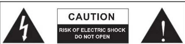
CAUTION: TO REDUCE THE RISK OF ELECTRIC SHOCK, DO NOT REMOVE COVER (OR BACK) NO USER SERVICEABLE PARTS INSIDE REFER SERVICING TO QUALIFIED PERSONNEL

The lightning flash with arrowhead symbol, within an equilateral triangle, is intended to alert the user to the presence of uninsulated "dangerous voltage" within the product's enclosure that may be of sufficient magnitude to constitute a risk of electric shock to persons.

The exclamation point within an equilateral triangle is intended to alert the user to the presence of important operating and maintenance (servicing) instructions in the literature accompanying the appliance.
WARNING: To reduce the risk of fire electric shock, do not expose this apparatus to rain or moisture.
CAUTION: Use of controls or adjustments or performance of procedures other than thosepecified may result in hazardous radiation exposure.
INTRODUCTION
Congratulations on your purchase of a fantastic MAX series power amplifier from Phonic. Based on years of experience in designing and manufacturing professional audio equipment, we at Phonic designed this power amplifier for those who need an extremely powerful, reliable and sturdy amplifier with a small footprint. Taking advantage of its huge heat sink as well as its variable speed fan that auto-adjusts fan speed depending on the temperature of the machine during operation, MAX power amps are always able to perform. Its professional quality output and its sturdy case design make this unit great for various locations like churches, concert tours, stages, disco, pubs, or any place that requires amplifier installation.
This unit is designed with great care and great attention to details, so please read this manual carefully. Look after it and keep it in a safe place for future reference.
FEATURES
- Up to 600 Watts of power in a 2U footprint
- Output power per channel: 300W at 4 ohms
- High current toroidal transformer allowing high power output with low noise and low distortion
• Balanced XLR inputs - Binding post and speakon outputs
- Front mounted gain controls for easy access
• Signal and Peak LED indicators to monitor system performance - Protection: short circuit, thermal, subsonic, RF protection, output DC offset, power on/off muting
INSTALLATION
MOUNTING THE UNIT
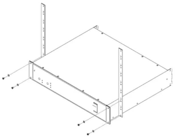
Designed to fit into a standard 19-inch rack, this unit only takes up 2 units of rack space. Secure the unit with 4 rack-mount screws and cup washers. In general, power amplifiers usually are heavier than any other audio equipment, so when installing this unit onto a rack, begin placing it from the bottom of the rack. Leave 1-rack space between power amplifiers and other devices to guarantee better cooling (see Figure 1).
natural_image
Technical line drawing of a server rack unit with mounting brackets and vertical measurement lines (no text or symbols)Figure 1 Rack Mount
PLEASE NOTE
- Check the AC voltage before connecting the power plug to the outlet. Make sure the AC power supply shares the same voltage used in your country (For example, while some countries use 100V, others use 120V, 230V, or 240V). Please ensure your device is properly grounded. Under no circumstances should the ground pin be removed from the AC power cable.
- Before turning on the power, make sure the gain controls are turned all the way down to prevent other equipment from harm.
- Check your cables regularly and label each end clearly for easy identification.
- Always turn the power off before connecting to and disconnecting from the unit.
- NEVER use solvents to clean the unit. Clean it with a soft and damp or dry cloth.
GETTING STARTED
The following steps will help you set up your amplifier, and get the levels just right.
- Ensure that you turn the amplifier's power switch is off and that the AC power connector is disconnected.
- Turn down both level controls.
- Decide which operating mode is best for your purposes: Stereo, Parallel or Bridge.
Stereo mode is the most common operation mode of amplifiers, where input channel 1 is sent directly through to output channel 1. Similarly, input channel 2 is sent directly through to output channel 2.
In Parallel Mode, users are able to utilize a mono signal from input channel 1 and send the signal through both output channels 1 and 2. These outputs are controlled with their own individual level controls.
Bridge Mode takes the signals from input channel 1 and sends it through a single output. The output power of the both channels is combined when in bridge mode. The signal is output through either output channel 1's speakon connection, or through the binding post connections on channels 1 (+) and 2 (-).
- Set the Stereo / Parallel / Bridge switch according to your selection.
- Make connections from your mixer main output to your MAX amplifier's inputs using balanced XLR cables. Remember that when using Parallel mode, you need only connect a signal source to input channel 1.
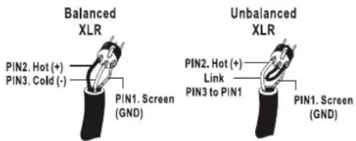
Balanced XLR inputs are wired as follows:
$$ \text { Pin } 1 = \text { Ground; } \text { Pin } 2 = \text { Hot } (+); \text { Pin } 3 = \text { Cold } (-) $$
- Connect speaker cables to the speakon or binding post speaker outputs.
When in Parallel and Stereo mode, the binding post connectors are wired as follows:
$$ \text { red } = \text { hot } (+ \text { speaker terminal }) $$
$$ \text { black } = \text { cold } (- \text { speaker terminal }) $$
When in Parallel or Stereo mode, the Speakon connectors are wired as follows:
$$ 1 + = \text { hot } (+ \text { speaker terminal }) $$
$$ 1 - = \text { cold } (- \text { speaker terminal }) $$

When in Bridge mode, the binding post connectors are wired as follows:
Channel 1 red post = hot (+ speaker terminal)
Channel 2 red post = cold (− speaker terminal)
Do not use the black terminals.
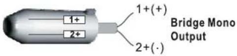
When in Bridge mode, the Speakon connectors are wired as follows:
$$ 1 + = \text { hot } (+ \text { speaker terminal }) $$
$$ 2 + = \text { cold } (- \text { speaker terminal }) $$
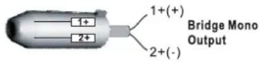
NOTE: When in Bridge mode, ensure that only the channel 1 Speakon connector is used.
- Plug all of your system's various components into suitable AC power outlets, making sure that they are grounded and able to deliver the appropriate amount of current.
- Ensure that your signal source is powered up and delivering a signal to the MAX amp.
- Turn the MAX's power switch on. You should be greeted by an illuminated POWER LED.
- Turn up both of the MAX's level controls slowly. The SIGNAL light should come on if any signal is present. The more you turn the level control up, the louder the music should get. If the CLIP LED comes on, turn down either the corresponding level control or your signal source until the CLIP LED lights up only occasionally, or just below the point where it may flash.
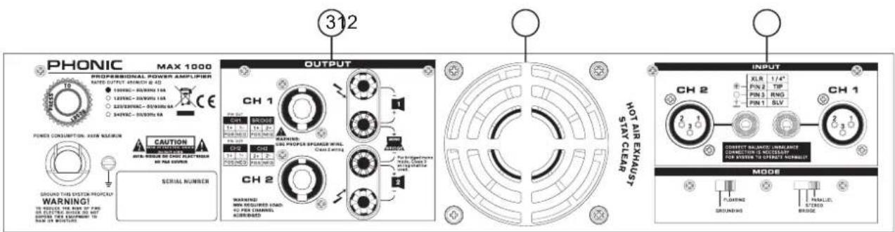
PRODUCT OVERVIEW
REAR PANEL
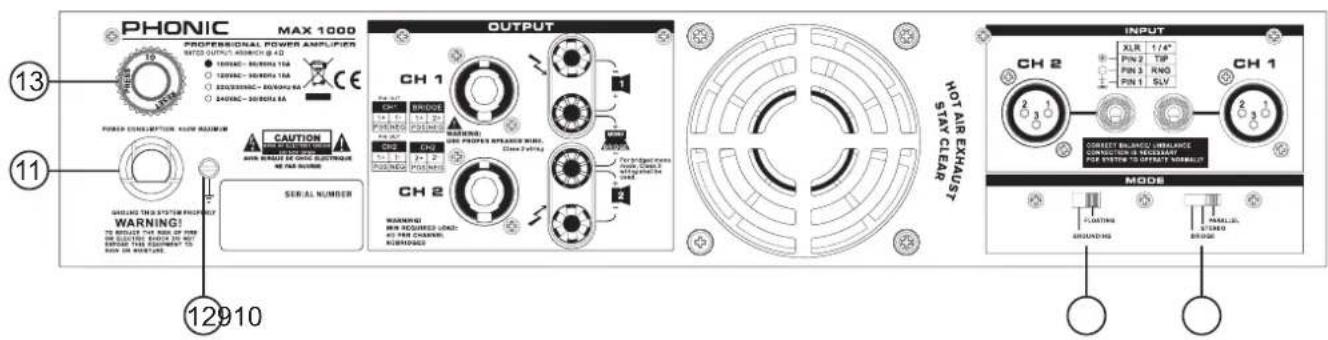
1. HEAT VENTILATION
This unit comes with variable speed fan that auto-adjusts fan speed depending on the temperature of the machine during operation. Be sure not to obstruct the heat vents in any way. This will ensure the amplifier is always properly ventilated.
CONNECTIONS
2. INPUT
With these balanced XLR and 1/4" input jacks, you can use any XLR or 1/4" phone jack connector. These input jacks accept balanced and unbalanced inputs. When sending unbalanced signals, the 3rd pin and the 1st pin of the XLR connector should be connected (see Figure 2).
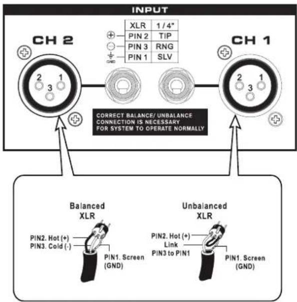
Figure 2 Input Wiring
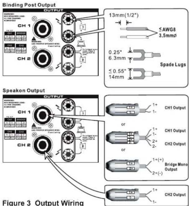
3. OUTPUT
Binding posts and speakon connectors make up the unit's output section. Loudspeakers can easily be connected using banana plugs, spade lugs, bare wires or speakon connector. More people prefer using speakon than other connectors because it's the least likely to be disconnected by accident or cause electrical shock. Because speakon comes with four wires inside, you can connect to two speakers with only one channel output. Be careful when making connections since improper connecting could cause the unit to short circuit. The minimum impedance setting for STEREO and PARALLEL operation is 4 ohm, while 8 ohm is the minimum for BRIDGE MONO (see Figure 3).
PHONIC MAX 1000
PROFESSIONAL POWER AMPLIFIER
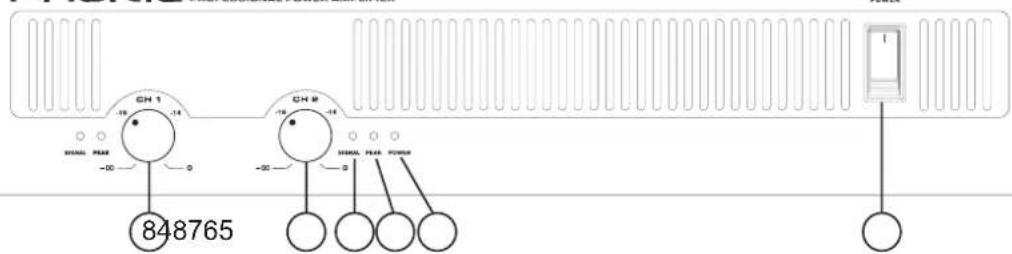
OPERATION
FRONT PANEL
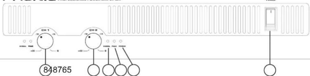
4. POWER SWITCH
This switch turns the power of the unit on. Remember to turn the gain controls down before turning power on or off, even though it comes with a POWER ON / OFF MUTING feature. In general, the power amplifier should be the last piece of audio equipment to be powered on, and the first to be powered off, in a PA system.
5. POWER LED
This blue LED comes on when power is on.
6. PEAK LED
When the input signal level becomes too high, causing input signal to loss definition and to distort, this red LED comes on. When this happens, turn the gain control down until the PEAK LED no longer comes on or remains on continuously.
7. SIGNAL LED
Every channel comes with a signal LED, allowing user to monitor signal level. A minimum level of -30dBu is required for the LED to go on.
8. GAIN CONTROLS
These two rotary knobs control the signal level of the input. Center detented control allows precise volume setting. Slowly turn the knob clockwise to increase input level, but make sure that PEAK LED does not remain on or blink constantly.
REAR PANEL
9. PARALLEL / STEREO / BRIDGE MONO
OPERATION MODE
There are three operation modes for different use. To avoid damaging your PA system, remember to turn the power off before switching from one mode to the other. See the OPERATING MODES section of this manual for more details.
10. GROUNDING / FLOATING SWITCH
This switch allows the circuit and chassis grounds to be separated in case of a ground conflict. In normal use the switch should be in the Ground On position. Lifting the ground (Floating position) may resolve the ground conflict, but means that circuit grounding will depend on other connected components. Deficiencies in other components' grounding will affect the sound and a serious electric fault with the amplifier could damage other components in the system.
11. CHASSIS GROUNDING CONNECTING POINT
To avoid the possibility of ground loop, this unit comes with chassis grounding point allowing it to be connected to other units for sharing a common grounding.
12. POWER CORD
This cord draws electricity from power outlet. Check the AC voltage of your unit before connecting the power plug to the outlet and ensure that the AC requirements of your MAX amplifier are the same as those used in your country.
13. RESET SWITCH
Push this button to reset the unit in the unlikely event that it locks up.
4 MAX 1000
OPERATING MODES
PARALLEL
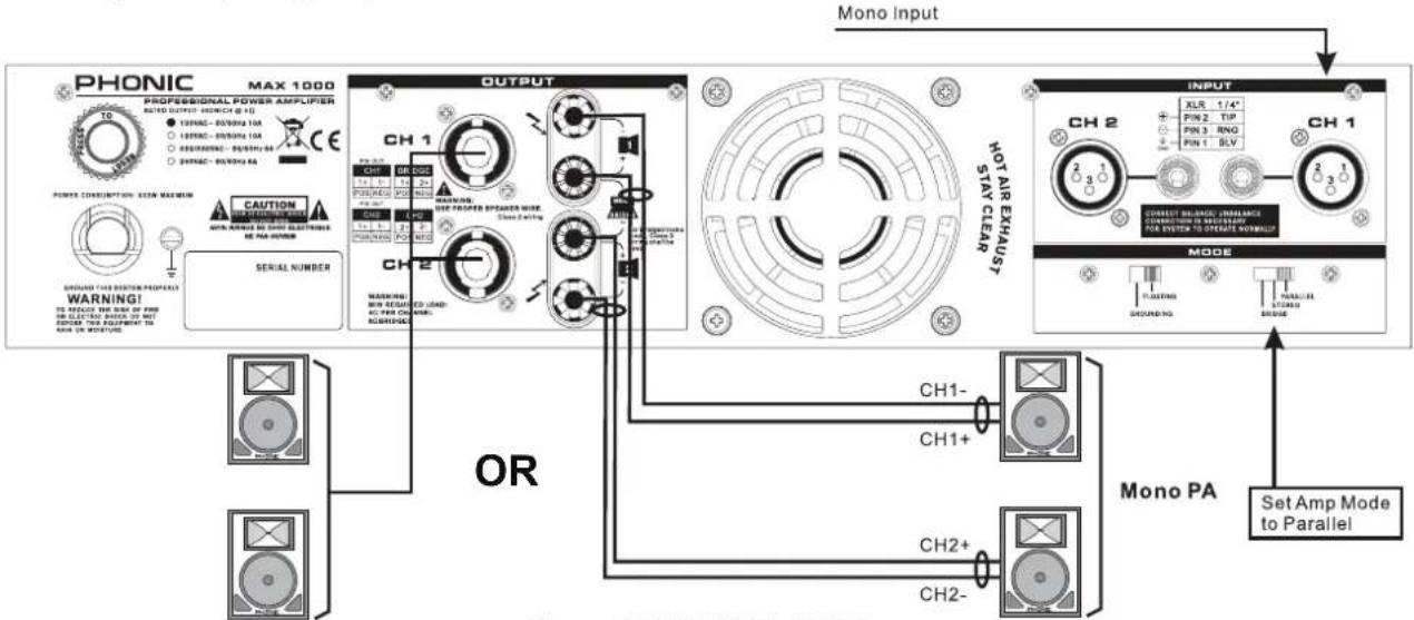
When set to PARALLEL mode, the input signal of Channel 2 parallels the input signal of Channel 1, so only one input jack is needed for the signal source. Even though the input signal of both channels parallels each other, the output level of each channel is determined by its own independent gain controls. So the two channels sharing the same signal do not share the same output level (see Figure 4).
flowchart
graph TD
    A["PROFESSIONAL POWER AMPLIFIER"] --> B["MAX 1000"]
    B --> C["OUTPUT"]
    C --> D["NOT AIR EXHAUST"]
    D --> E["MODE"]
    E --> F["Set Amp Mode to Parallel"]

    subgraph Power Consumption
        G["POWER CONSUMPTION: ESTM MARGIN"]
        H["MINI NATURE: ON CHINA ELECTRONE & PA SWITCH"]
        I["SERIAL NUMBER"]
        J["OR"]
    end

    subgraph Channel
        K["CH1"] --> L["CH2"]
        M["CH2+"] --> N["CH2-"]
    end

    subgraph Signal
        O["CH1-"] --> P["CH1+"]
        Q["CH2+"] --> R["CH2-"]
    end

    style A fill:#f9f,stroke:#333
    style B fill:#ccf,stroke:#333
    style C fill:#cfc,stroke:#333
    style D fill:#fcc,stroke:#333
    style E fill:#cff,stroke:#333
    style F fill:#ffc,stroke:#333
    style G fill:#f9f,stroke:#333
    style H fill:#f9f,stroke:#333
    style I fill:#f9f,stroke:#333
    style J fill:#f9f,stroke:#333
    style K fill:#cfc,stroke:#333
    style L fill:#cfc,stroke:#333
    style M fill:#cfc,stroke:#333
    style N fill:#cfc,stroke:#333
    style O fill:#cfc,stroke:#333
    style P fill:#cfc,stroke:#333
    style Q fill:#cfc,stroke:#333
    style R fill:#cfc,stroke:#333
    style S fill:#cfc,stroke:#333
    style T fill:#cfc,stroke:#333
    style U fill:#cfc,stroke:#333
    style V fill:#cfc,stroke:#333
    style W fill:#cfc,stroke:#333
    style X fill:#cfc,stroke:#333
    style Y fill:#cfc,stroke:#333
    style Z fill:#cfc,stroke:#333
Figure 4 PARALLEL MODE
STEREO
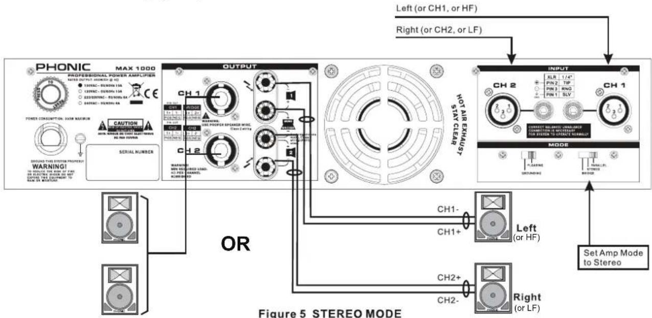
STEREO mode is the most frequently used mode among the three. Each channel is independent of the other, carrying its own input signal, with its own gain control. Stereo mode comes in left and right channels (see Figure 5).
A) When one channel is assigned for left channel, make sure the other channel is assigned for the right.
B) User can use the unit for mono output, with one as main and the other as monitor.
C) This power amplifier can also be used for bi-amplification. One channel can be used for driving low frequencies, while the other is used for driving high frequencies.
flowchart
graph TD
    A["PHONIC MAX 1000 PROFESSIONAL POWER AMPLIFIER RATED OUTPUT AMOUNT (Ω) 10"]
    B["OUTPUT"] --> C["CH1"]
    B --> D["CH2"]
    B --> E["OR"]
    B --> F["CH1-"]
    B --> G["CH2+"]
    B --> H["CH2-"]
    I["MODE"] --> J["INPUT"]
    J --> K["CH2"]
    J --> L["CH1"]
    M["OR"] --> N["PROFESSIONAL POWER AMPLIFIER RATED OUTPUT AMOUNT (Ω) 10"]
    M --> O["PROFESSIONAL POWER AMPLIFIER RATED OUTPUT AMOUNT (Ω) 12"]
    M --> P["PROFESSIONAL POWER AMPLIFIER RATED OUTPUT AMOUNT (Ω) 83"]
    M --> Q["PROFESSIONAL POWER AMPLIFIER RATED OUTPUT AMOUNT (Ω) 64"]
    M --> R["PROFESSIONAL POWER AMPLIFIER RATED OUTPUT AMOUNT (Ω) 59"]
    S["PROFESSIONAL POWER AMPLIFIER RATED OUTPUT AMOUNT (Ω) 10"] --> T["POWER CONSUMPTION, MAX MAXIMUM"]
    U["PROFESSIONAL POWER AMPLIFIER RATED OUTPUT AMOUNT (Ω) 12"] --> V["PROFESSIONAL POWER AMPLIFIER RATED OUTPUT AMOUNT (Ω) 10"]
    W["PROFESSIONAL POWER AMPLIFIER RATED OUTPUT AMOUNT (Ω) 83"] --> X["PROFESSIONAL POWER AMPLIFIER RATED OUTPUT AMOUNT (Ω) 64"]
    Y["PROFESSIONAL POWER AMPLIFIER RATED OUTPUT AMOUNT (Ω) 59"] --> Z["PROFESSIONAL POWER AMPLIFIER RATED OUTPUT AMOUNT (Ω) 59"]
    AA["PROFESSIONAL POWER AMPLIFIER RATED OUTPUT AMOUNT (Ω) 10"] --> AB["PROFESSIONAL POWER AMPLIFIER RATED OUTPUT AMOUNT (Ω) 10"]
    AC["PROFESSIONAL POWER AMPLIFIER RATED OUTPUT AMOUNT (Ω) 12"] --> AD["PROFESSIONAL POWER AMPLIFIER RATED OUTPUT AMOUNT (Ω) 12"]
    AE["PROFESSIONAL POWER AMPLIFIER RATED OUTPUT AMOUNT (Ω) 83"] --> AF["PROFESSIONAL POWER AMPLIFIER RATED OUTPUT AMOUNT (Ω) 64"]
    AG["PROFESSIONAL POWER AMPLIFIER RATED OUTPUT AMOUNT (Ω) 59"] --> AH["PROFESSIONAL POWER AMPLIFIER RATED OUTPUT AMOUNT (Ω) 59"]
    AI["PROFESSIONAL POWER AMPLIFIER RATED OUTPUT AMOUNT (Ω) 10"] --> AJ["PROFESSIONAL POWER AMPLIFIER RATED OUTPUT AMOUNT (Ω) 10"]
    AK["PROFESSIONAL POWER AMPLIFIER RATED OUTPUT AMOUNT (Ω) 12"] --> AL["PROFESSIONAL POWER AMPLIFIER RATED OUTPUT AMOUNT (Ω) 12"]
    AM["PROFESSIONAL POWER AMPLIFIER RATED OUTPUT AMOUNT (Ω) 83"] --> AN["PROFESSIONAL POWER AMPLIFIER RATED OUTPUT AMOUNT (Ω) 64"]
    AO["PROFESSIONAL POWER AMPLIFIER RATED OUTPUT AMOUNT (Ω) 59"] --> AP["PROFESSIONAL POWER AMPLIFIER RATED OUTPUT AMOUNT (Ω) 59"]
    AQ["PROFESSIONAL POWER AMPLIFIER RATED OUTPUT AMOUNT (Ω) 10"] --> AR["PROFESSIONAL POWER AMPLIFIER RATED OUTPUT AMOUNT (Ω) 10"]
    AS["PROFESSIONAL POWER AMPLIFIER RATED OUTPUT AMOUNT (Ω) 12"] --> AT["PROFESSIONAL POWER AMPLIFIER RATED OUTPUT AMOUNT (Ω) 12"]
    AU["PROFESSIONAL POWER AMPLIFIER RATED OUTPUT AMOUNT (Ω) 83"] --> AV["PROFESSIONAL POWER AMPLIFIER RATED OUTPUT AMOUNT (Ω) 64"]
    AW["PROFESSIONAL POWER AMPLIFIER RATED OUTPUT AMOUNT (Ω) 59"] --> AX["PROFESSIONAL POWER AMPLIFIER RATED OUTPUT AMOUNT (Ω) 59"]
    AY["PROFESSIONAL POWER AMPLIFIER RATED OUTPUT AMOUNT (Ω) 10"] --> AZ["PROFESSIONAL POWER AMPLIFIER RATED OUTPUT AMOUNT (Ω) 10"]
    BA["PROFESSIONAL POWER AMPLIFIER RATED OUTPUT AMOUNT (Ω) 12"] --> BB["PROFESSIONAL POWER AMPLIFIER RATED OUTPUT AMOUNT (Ω) 12"]
    BC["PROFESSIONAL POWER AMPLIFIER RATED OUTPUT AMOUNT (Ω) 83"] --> BD["PROFESSIONAL POWER AMPLIFIER RATED OUTPUT AMOUNT (Ω) 64"]
    BE["PROFESSIONAL POWER AMPLIFIER RATED OUTPUT AMOUNT (Ω) 59"] --> BF["PROFESSIONAL POWER AMPLIFIER RATED OUTPUT AMOUNT (Ω) 59"]
    BG["PROFESSIONAL POWER AMPLIFIER RATED OUTPUT AMOUNT (Ω) 10"] --> BH["PROFESSIONAL POWER AMPLIFIER RATED OUTPUT AMOUNT (Ω) 10"]
    BI["PROFESSIONAL POWER AMPLIFIER RATED OUTPUT AMOUNT (Ω) 12"] --> BJ["PROFESSIONAL POWER AMPLIFIER RATED OUTPUT AMOUNT (Ω) 12"]
    BK["PROFESSIONAL POWER AMPLIFIER RATED OUTPUT AMOUNT (Ω) 83"] --> BL["PROFESSIONAL POWER AMPLIFIER RATED OUTPUT AMOUNT (Ω) 64"]
    BM["PROFESSIONAL POWER AMPLIFIER RATED OUTPUT AMOUNT (Ω) 59"] --> BN["PROFESSIONAL POWER AMPLIFIER RATED OUTPUT AMOUNT (Ω) 59"]
    BO["PROFESSIONAL POWER AMPLIFIER RATED OUTPUT AMOUNT (Ω) 10"] --> BP["PROFESSIONAL POWER AMPLIFIER RATED OUTPUT AMOUNT (Ω) 10"]
    BQ["PROFESSIONAL POWER AMPLIFIER RATED OUTPUT AMOUNT (Ω) 12"] --> BR["PROFESSIONAL POWER AMPLIFIER RATED OUTPUT AMOUNT (Ω) 12"]
    BS["PROFESSIONAL POWER AMPLIFIER RATED OUTPUT AMOUNT (Ω) 83"] --> BT["PROFESSIONAL POWER AMPLIFIER RATED OUTPUT AMOUNT (Ω) 64"]
    BU["PROFESSIONAL POWER AMPLIFIER RATED OUTPUT AMOUNT (Ω) 59"] --> BV["PROFESSIONAL POWER AMPLIFIER RATED OUTPUT AMOUNT (Ω) 59"]
    BW["PROFESSIONAL POWER AMPLIFIER RATED OUTPUT AMOUNT (Ω) 10"] --> BX["PROFESSIONAL POWER AMPLIFIER RATED OUTPUT AMOUNT (Ω) 10"]
    BY["PROFESSIONAL POWER AMPLIFIER RATED OUTPUT AMOUNT (Ω) 12"] --> BZ["PROFESSIONAL POWER AMPLIFIER RATED OUTPUT AMOUNT (Ω) 12"]
    CA["PROFESSIONAL POWER AMPLIFIER RATED OUTPUT AMOUNT (Ω) 83"] --> CB["PROFESSIONAL POWER AMPLIFIER RATED OUTPUT AMOUNT (Ω) 64"]
    CC["PROFESSIONAL POWER AMPLIFIER RATED OUTPUT AMOUNT (Ω) 59"] --> CD["PROFESSIONAL POWER AMPLIFIER RATED OUTPUT AMOUNT (Ω) 59"]
    CE["PROFESSIONAL POWER AMPLIFIER RATED OUTPUT AMOUNT (Ω) 10"] --> CF["PROFESSIONAL POWER AMPLIFIER RATED OUTPUT AMOUNT (Ω) 10"]
    CG["PROFESSIONAL POWER AMPLIFIER RATED OUTPUT AMOUNT (Ω) 12"] --> DH["PROFESSIONAL POWER AMPLIFIER RATED OUTPUT AMOUNT (Ω) 12"]
    DI["PROFESSIONAL POWER AMPLIFIER RATED OUTPUT AMOUNT (Ω) 83"] --> DJ["PROFESSIONAL POWER AMPLIFIER RATED OUTPUT AMOUNT (Ω) 64"]
    DK["PROFESSIONAL POWER AMPLIFIER RATED OUTPUT AMOUNT (Ω) 59"] --> DL["PROFESSIONAL POWER AMPLIFIER RATED OUTPUT AMOUNT (Ω) 59"]
    DM["PROFESSIONAL POWER AMPLIFIER RATED OUTPUT AMOUNT (Ω) 10"] --> DE["PROFESSIONAL POWER AMPLIFIER RATED OUTPUT AMOUNT (Ω) 10"]
    DF["PROFESSIONAL POWER AMPLIFIER RATED OUTPUT AMOUNT (Ω) 12"] --> DG["PROFESSIONAL POWER AMPLIFIER RATED OUTPUT AMOUNT (Ω) 12"]
    DH --> DH
    DE --> DH
    DE --> DH
    DE --> DH
    DE --> DH
    DE --> DH
    DE --> DH
    DE --> DH
    DE --> DH
    DE --> DH
    DE --> DH
    DE --> DH
    DE --> DH
    DE --> DH
    DE --> DH
    DE --> DH
    DE --> DH
    DE --> DH
    DE --> DH
    DE --> DH
    DE --> DH
    BE --> BE
    BE --> BE
    BE --> BE
    BE --> BE
    BE --> BE
    BE --> BE
    BE --> BE
    BE --> BE
    BE --> BE
    BE --> BE
    BE --> BE
    BE --> BE
    BE --> BE
    BE --> BE
    BE --> BE
    BE --> BE
    BE --> BE
    BE --> BE
    BE --> BE
    BE --> BE
    BE --> BO
    BE --> BO
    BE --> BO
    BE --> BO
    BE --> BO
    BE --> BO
    BE --> BO
    BE --> BO
    BE --> BO
    BE --> BO
    BE --> BO
    BE --> BO
    BE --> BO
    BE --> BO
    BE --> BO
    BE --> BO
    BE --> BO
    BE --> BO
    BE --> BO
    BE --> BO
    BE --> DO
    BE --> DO
    BE --> DO
    BE --> DO
    BE --> DO
    BE --> DO
    BE --> DO
    BE --> DO
    BE --> DO
    BE --> DO
    BE --> DO
    BE --> DO
    BE --> DO
BRIDGE MONO
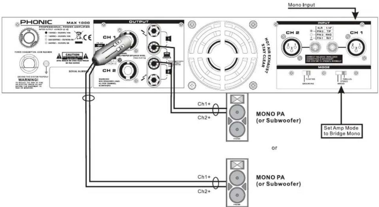
This mode is for those who need high level output. It combines the power of both channels to produce the maximum amount of power the unit can handle. Make sure your speaker can handle the higher wattage this mode offers.
Remember, the minimum impedance requirement is 4 ohm.
When using bridge mono mode, ensure only Channel 1 input is in use. When using speakon connectors, treat PIN 1+ as the "+" and PIN 2+ as the "-" ; when using binding posts, treat Channel 1 + as the "+" and Channel 2 + as the "-" . Do not use Channel 2's speakon output in this mode. When bridge mono, the gain control of Channel 1 controls the total level output (see Figure 6).
WARNING: Bridge mono operation produces higher current output than the other two operations, thus make sure the gain is set at the proper level and speakers being used can handle the wattage amplifier produce. Proper attention to wiring is greatly needed to prevent experiencing electric shock.
flowchart
graph TD
    A["PHONIC MAX 1000"] --> B["PROFESSIONAL POWER AMPLIFIER"]
    B --> C["OUTPUT"]
    C --> D["NOT AIR EXCHUST"]
    D --> E["MODE"]
    E --> F["Set Amp Mode to Bridge Mono"]

    subgraph Power CONSUMPTION: MAX Maximum
        G["POWER CONSUMPTION: MAX Maximum"]
        H["WARNING: MAX Minimum"]
        I["Warning: MAX Minimum"]
        J["Signal Number: CH1, CH2"]
    end

    subgraph CH1 & CH2
        K["CH1, CH2 signals"]
        L["CH1+"]
        M["CH2+"]
    end

    subgraph MODE
        N["INPUT"]
        O["SET AMP Mode to Bridge Mono"]
    end

    style A fill:#f9f,stroke:#333
    style B fill:#ccf,stroke:#333
    style C fill:#cfc,stroke:#333
    style D fill:#fcc,stroke:#333
    style E fill:#cff,stroke:#333
    style F fill:#ffc,stroke:#333
    style G fill:#fff,stroke:#333
    style H fill:#fff,stroke:#333
    style I fill:#fff,stroke:#333
    style J fill:#fff,stroke:#333
    style K fill:#fff,stroke:#333
    style L fill:#fff,stroke:#333
    style M fill:#fff,stroke:#333
    style N fill:#fff,stroke:#333
    style O fill:#fff,stroke:#333
    style P fill:#fff,stroke:#333
    style Q fill:#fff,stroke:#333
    style R fill:#fff,stroke:#333
    style S fill:#fff,stroke:#333
    style T fill:#fff,stroke:#333
    style U fill:#fff,stroke:#333
    style V fill:#fff,stroke:#333
    style W fill:#fff,stroke:#333
    style X fill:#fff,stroke:#333
    style Y fill:#fff,stroke:#333
    style Z fill:#fff,stroke:#333
    style AA fill:#fff,stroke:#333
    style AB fill:#fff,stroke:#333
    style AC fill:#fff,stroke:#333
    style AD fill:#fff,stroke:#333
    style AE fill:#fff,stroke:#333
    style AF fill:#fff,stroke:#333
    style AG fill:#fff,stroke:#333
    style AH fill:#fff,stroke:#333
    style AI fill:#fff,stroke:#333
    style AJ fill:#fff,stroke:#333
    style AK fill:#fff,stroke:#333
    style AL fill:#fff,stroke:#333
    style AM fill:#fff,stroke:#333
    style AN fill:#fff,stroke:#333
    style AO fill:#fff,stroke:#333
Figure 6 BRIDGE MONO MODE
PROTECTION
The unit comes with many circuitry protection features that protecting it and the speakers it's connected to from harm.
SHORT CIRCUIT: When speakers short circuit, this feature protects the amplifier by cutting off the output current to the speakers.
THERMAL: Heat is created during high level output – especially when operating under bridge mono mode. The unit comes with a variable speed fan that auto-adjusts the fan speed depending on the temperature of the machine. However, if for some reason the unit can not effectively vent out excessive heat, this feature will protect the unit from over-heating by shutting the unit down.
OUTPUT DC OFFSET: When a direct current enters the connection between the power amplifier and speakers, it will negatively affect the speakers by causing the drivers and cones to work under stressful conditions. This feature ensures this does not happen by cutting off the output current to the speakers when such a situation occurs.
POWER ON / OFF MUTING: There is a two to three second delay before the unit sends out any signal. During this short delay, the entire system will be muted ensuring no signal affects your signal.
SUBSONIC: Frequencies below 10Hz contain high level of energy that can be harmful and stressful to many speakers. Since the normal human listening range is between 20 Hz and 20 kHz, this unit comes with a feature that helps filter out any frequency that is below 10 Hz to protect your speakers.
RF PROTECTION: Radio waves are everywhere. This feature prevents radio frequency interference from affect your signal by filtering out signals above 200 kHz. This ensures that radio program signals do not entering the unit.
AC POWER CONSIDERATIONS
The voltage level of the MAX amplifier will depend on your region. Ensure that the local voltage levels are identical by those required by your amplifier before attempting to connect it to an AC outlet. This is particularly important if you intend to take the amplifier overseas.
Users are advised that they do not remove the ground pin on the MAX amplifier's AC connector under any circumstances.
As the amount of power that the MAX amplifier consumes can differ greatly depending on the program material being amplified, it's important that a stiff supply of AC power is available for the unit. The more power available to the unit, the better the output will sound; particularly in low frequency peaks. If you have more than one amplifier sharing a single AC outlet, turning them on at the same time should be avoided at all costs. Turning them on in sequential order will help prevent tripping any circuit breakers.
INPUT WIRING
For balanced signals, users should use 3-conductor shielded cable with XLR connectors on either end. For unbalanced signals, 2-conductor shielded cable with XLR connectors on either end can be used instead. Balanced cables should be wired according to Audio Engineering Society standards.
XLR? The name of this kind of connector is derived from an X connector from Cannon. These are the large, round connectors that contain three small pins that are arranged in a triangular shape.
Hot (+) - Pin 2
Cold (-) - Pin 3
Shield (Gnd) - Pin 1
OUTPUT WIRING
We recommend users use stranded, heavy gauge wire for connecting to the binding post outputs of the MAX amplifier. As the distance between the amplifier and the speaker increases, it's important that the gauge of the cable decreases. Speaker wire has resistance, so the longer the cables are run the more this resistance affects the signal. The lower the gauge, the thicker the wire, and the less resistance the cable will offer. This ensures that the power lost through speaker wires is less than half a decibel.
| Cable Length | Load Wire Gauge | |
| < 25 ft. | 4Ω | 16 |
| 8Ω | 18 | |
| 25 – 40 ft. | 4Ω | 14 |
| 8Ω | 18 | |
| 40 – 60 ft. | 4Ω | 12 |
| 8Ω | 16 | |
| 60 – 100 ft. | 4Ω | 10 |
| 8Ω | 14 | |
| 100 – 150 ft. | 4Ω | 8 |
| 8Ω | 12 | |
Using Binding Posts in Stereo/Parallel Mode
Either single or double banana plugs can be used when using binding post outputs. Users may also opt to use spade lugs or bare wires. To use bare wires, unscrew the binding posts to reveal the holes on the side of the mental conductors within. Insert the stripped wire and refasten the binding posts. Ensure that no strands of wire are loose from the connection.
When using binding posts, the red post is positive, the black post is negative (and they are labeled as such). Connecting a speaker's connections the wrong way around will cause a signal's polarity to be messed around and will have quite undesirable results.
Using Speakon Connections in Stereo or Parallel Mode
When wiring Speakon cables for stereo or parallel mode operation, do so as follows:

Using Binding Posts in Bridge Mode
When using Binding Posts under bridge mode, connect the positive (+) side of the speaker to the Channel 1 red binding post and the negative (-) side of the speaker to the Channel 2 red binding post.
Using Speakon Connections in Bridge Mode
When wiring Speakon cables for bridge mode operation, do so as follows:
TROUBLESHOOTING
No Power
- Perhaps the most obvious question, but is it plugged in?
- Is the AC outlet that the MAX amp is connected to active? Test it with a lamp.
• Is the power switched on? - Is the power LED illuminated? If not, make sure that the unit is plugged in, turned on and the AC outlet is live. If it is illuminated, check the "No Sound" section below.
- Failing all of this, the most likely cause is the fuse inside the amplifier's power supply has blown. As users cannot service this part, please contact your country's distributor for assistance. You can find their details on www.phonic.com/where.
No Sound
- Have you turned up the level controls? If not, turn them up slowly to see if you can hear anything.
- Is your source material turned up and active? Ensure that the level of the mixer (or whichever device is connected to your amplifier's inputs) is high enough to produce a signal. The signal LED on the front panel should give you some idea of whether this is so.
- Check the temperature of the unit by putting a hand nearby. If there is no heat, you're fine. If you can feel obvious heat emitting from the unit, it's possible that the thermal protection function has kicked it. You may need to turn the unit off and wait for it to cool down before it can function as normal.
- Ensure your speakers to make sure they are working correctly. If your speakers have fuses, check if they've blown.
Poor sound
- Is the signal loud and distorted? If so, turn down the level of the source signal.
- Is the clip LED flashing quickly or staying constantly on? If so, try reducing the Amplifier's level controls.
- Ensure that the input connectors are pushed firmly into the jack. Make sure your speakers are connected correctly.
- Try connecting a set of headphones into your signal source to see how the signal sounds there. If you're getting the same result, then the problem is your source rather than the amplifier.
SPECIFICATIONS
| Stereo Mode (driving both channels) Continuous | Average Output Power Per Channel |
| 8Ω EIA 1kHz 0.1%THD 200W | |
| 4Ω EIA 1kHz 0.1%THD 300W | |
| Bridge Mono Mode Continuous Average Output Power | |
| 8Ω EIA 1kHz 0.1%THD 600W | |
| Output Circuitry Class AB | |
| Input Sensitivity @ 8Ω 1.23V (+4dBu) | |
| Distortion (SMPTE-IM) <0.01% | |
| Noise (unweighted 20 Hz - 20 kHz below rated output) | 100dB |
| Damping Factor >300 @ 8Ω | |
| Frequency Response 20 Hz-20KHz, +0/-1dB; -3dB points: 5Hz-50KHz | |
| Input Impedance 20 kΩ balanced, 10 kΩ unbalanced | |
| Cooling Continuous variable-speed fan, front-to-rear air flow | |
| Connectors (each channel) Input: XLR; Output: Speakon and binding posts | |
| Indicators Power: Blue LED; Signal: Green LED; Peak: Red LED | |
| Controls | |
| Front Panel CH1 & CH2 GAIN knobs with 21 detents | |
| Rear Panel | Slide switches: Operation mode: Parallel, Bridge, Stereo; Current-Break reset button |
| Protection Circuitry | Short circuit, thermal, subsonic, RF protection, output DC offset, power on/off muting |
| Power Consumption 600W | |
| Power Requirement (depends on region) | 100~120VAC, 220~240VAC, 50/60Hz |
| Dimensions (WxHxD) | 482.6 x 88 x 415 mm (19" x 3.46" x 15.9") |
| Weight | 14.6 kg (32.2 lbs) |
DIMENSIONS
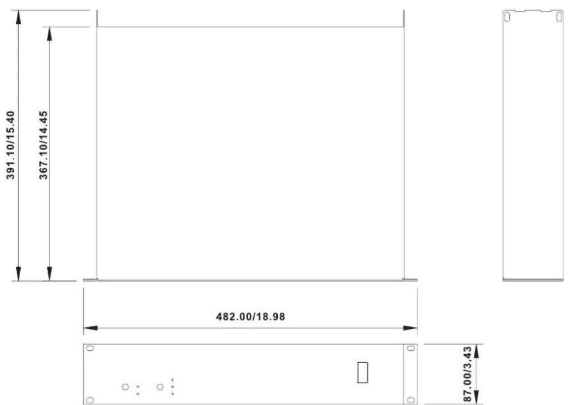
All measurements are shown in mm/inches.
SERVICE AND REPAIR
For replacement parts, service and repairs please contact the Phonic distributor in your country. Phonic does not release service manuals to consumers, and advice users to not attempt any self repairs, as doing so voids all warranties. You can locate a dealer near you at http://www.phonic.com/where/.
WARRANTY INFORMATION
Phonic stands behind every product we make with a no-hassles warranty. Warranty coverage may be extended, depending on your region. Phonic Corporation warrants this product for a minimum of one year from the original date of purchase against defects in material and workmanship under use as instructed by the user's manual. Phonic, at its option, shall repair or replace the defective unit covered by this warranty. Please retain the dated sales receipt as evidence of the date of purchase. You will need it for any warranty service. No returns or repairs will be accepted without a proper RMA number (return merchandise authorization). In order to keep this warranty in effect, the product must have been handled and used as prescribed in the instructions accompanying this warranty. Any tampering of the product or attempts of self repair voids all warranty. This warranty does not cover any damage due to accident, misuse, abuse, or negligence. This warranty is valid only if the product was purchased new from an authorized Phonic dealer/distributor. For complete warranty policy information, please visit http://www.phonic.com/warranty/.
CUSTOMER SERVICE AND TECHNICAL SUPPORT
We encourage you to visit our online help at http://www.phonic.com/support/. There you can find answers to frequently asked questions, tech tips, driver downloads, returns instruction and other helpful information. We make every effort to answer your questions within one business day.
support@phonic.com
http://www.phonic.com
MANUAL DEL USUARIO
CONTENIDO
INTRODUCCIÓN....1
CARACTERÍSTICAS....1
INSTALACIÓN....1
PRIMEROS PASOS....2
PRODUCT OVERVIEW....3
PANEL DORSAL....3
CONEXIONES....3
OPERACIÓN......4
PANEL FRONTAL....4
PANEL DORSAL....4
natural_image
Technical line drawing of a rectangular electronic device with mounting brackets and a vertical ruler, no text or symbols present.Figure 1 Rack Mount
INICIANDO
PHONIC MAX 1000
PROFERRIONAL POWER AMPLIFIER
OPERACIÓN
PANEL FRONTAL
4. INTERRUPTOR DE ENERGÍA
Figure 6 BRIDGE MONO MODE
PROTECCIONES
FCC Caution: To assure continued compliance, any changes or modifications not expressly approved by the party responsible for compliance could void the user's authority to operate this equipment. (Example - use only shielded interface cables when connecting to computer or peripheral devices).
THIS DEVICE COMPLIES WITH PART 74 OF THE FCC RULES. This equipment complies with FCC RF radiation exposure limits set forth for an uncontrolled environment.


support@phonic.com
http://www.phonic.com
PHONIC
NOTES
PHONIC
WWW.PHONIC.COM
- IMPORTANT SAFETY INSTRUCTIONS
- INTRODUCTION
- FEATURES
- INSTALLATION
- MOUNTING THE UNIT
- PLEASE NOTE
- GETTING STARTED
- PRODUCT OVERVIEW
- REAR PANEL
- HEAT VENTILATION
- CONNECTIONS
- INPUT
- OUTPUT
- OPERATION
- FRONT PANEL
- POWER SWITCH
- POWER LED
- PEAK LED
- SIGNAL LED
- GAIN CONTROLS
- PARALLEL / STEREO / BRIDGE MONO
- OPERATION MODE
- GROUNDING / FLOATING SWITCH
- CHASSIS GROUNDING CONNECTING POINT
- POWER CORD
- RESET SWITCH
- OPERATING MODES
- PARALLEL
- STEREO
- BRIDGE MONO
- PROTECTION
- AC POWER CONSIDERATIONS
- INPUT WIRING
- OUTPUT WIRING
- Using Binding Posts in Stereo/Parallel Mode
- Using Speakon Connections in Stereo or Parallel Mode
- Using Binding Posts in Bridge Mode
- Using Speakon Connections in Bridge Mode
- TROUBLESHOOTING
- No Power
- No Sound
- Poor sound
- DIMENSIONS
- SERVICE AND REPAIR
- WARRANTY INFORMATION
- CUSTOMER SERVICE AND TECHNICAL SUPPORT
- MANUAL DEL USUARIO
- CONTENIDO
- INICIANDO
- OPERACIÓN
- PANEL FRONTAL
- INTERRUPTOR DE ENERGÍA
- PROTECCIONES
- NOTES
- PHONIC
Brand : PHONIC
Model : MAX 1000
Category : Receiver