EW75000 - Network card / adapter EtherWAN - Free user manual and instructions
Find the device manual for free EW75000 EtherWAN in PDF.


| Product Type | Hardened Wireless LAN Access Point / Client Bridge |
| Model | EW75000 Series (EW75000-08, EW75000-13, EW75200-0804, EW75200-1304) |
| Dimensions (H x W x D) | 270 x 270 x 73 mm (10.62 x 10.62 x 2.88 in) |
| Weight | 2.5 kg (5.5 lbs) |
| Power Source | Power over Ethernet (PoE) IEEE 802.3at, 13W max |
| Operating Temperature | -40°C to 75°C (-40°F to 167°F) |
| Protection Rating | IP67 (dust-tight, waterproof) |
| Wireless Standards | IEEE 802.11a/b/g/n/ac |
| Frequency Bands | 2.4 GHz (2412-2462 MHz) and 5 GHz (5150-5250, 5725-5850 MHz) |
| Max Data Rate | 2.4 GHz: 300 Mbps (802.11n), 5 GHz: 866 Mbps (802.11ac) |
| Channel Width | 2.4 GHz: 5/10/20/40 MHz; 5 GHz: 10/20/40/80 MHz |
| Antenna Options | Internal 19 dBi panel or external 8 dBi omni (depending on model); 2x2 MIMO |
| Ethernet Port | 1x 10/100/1000 RJ-45 with waterproof cap |
| LED Indicators | 8 LEDs: Power, Ethernet, 2.4G, 5G, 5-level signal strength |
| Security | WPA2, WPA, WEP, 256-bit AES-CCM, RADIUS, MAC filtering |
| Operating Modes | AP, Client Bridge (CPE), PTP Bridge, PTMP, WISP, Home AP, CAP |
| Management | Web-based (HTTPS), SSH, Telnet, SNMP, Winbox |
| Mounting | Pole or wall mount (bracket included) |
| Grounding | Dual grounding terminals; grounding wire included |
| Surge Protection | Optional external surge protector; some models have built-in gas discharge tube |
| Firmware Features | HWMP+ mesh, QoS, VLAN, OSPF, RIP, BFD, traffic shaping, bandwidth test |
| Warranty | EtherWAN warranty replacement policy (see website) |
Frequently Asked Questions - EW75000 EtherWAN
User questions about EW75000 EtherWAN
0 question about this device. Answer the ones you know or ask your own.
Ask a new question about this device
Download the instructions for your Network card / adapter in PDF format for free! Find your manual EW75000 - EtherWAN and take your electronic device back in hand. On this page are published all the documents necessary for the use of your device. EW75000 by EtherWAN.
USER MANUAL EW75000 EtherWAN
natural_image
Abstract blue brushstroke design resembling stylized letter 'y' or motion blur (no text or symbols)EtherWAN
natural_image
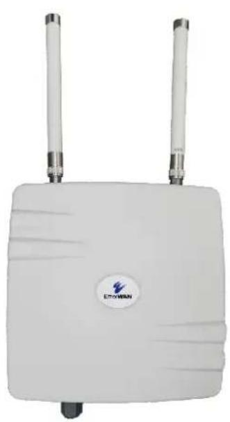
White wireless router device with two antennas and a circular logo (no readable text or symbols beyond branding)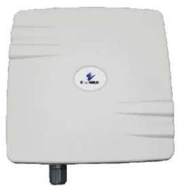
natural_image
White wireless router device with a circular logo and black port (no visible text or symbols)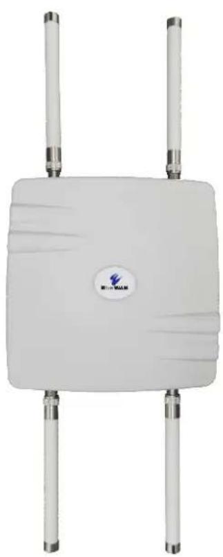
natural_image
White wireless router with four vertical tubes and a central logo (no readable text or symbols beyond branding)EW75000 Hardened Wireless LAN Access Point
Installation and Setup Guide
All Rights Reserved
Dissemination or reproduction of this document, or its contents, is not authorized except where expressly permitted. Violators are liable for damages. All rights reserved, for the purposes of patent application or trademark registration.
Disclaimer of Liability
The information contained in this document is subject to change without notice. EtherWAN is not liable for any errors or omissions contained herein or for resulting damage in connection with the information provided in this manual.
All other trademarks are property of their respective owners.
Warranty
For details on the EtherWAN warranty replacement policy, please visit our web site at:
https://www.etherwan.com/us/support/warranty-policy
Products Supported by this Manual:
EW75000-13, EW75200-1304, EW75000-08, EW75200-0804
Preface
Audience
This guide is designed for the person who installs, configures, deploys, and maintains the Ethernet network. This document assumes the reader has moderate hardware, computer, and Internet skills.
Document Revision Level
This section provides a history of the revision changes to this document.
| Revision | Document Version | Date | Description |
| A | Version 2 | 9/29/2019 | Specific to Version 2 of the EW75x00 Hardware |
Changes in this Revision
Added/Removed hardware specific differences between Version 1 and Version 2 of the EW75x00 Series. Software and Configuration are unchanged.
- Removed EW75000-21 and EW75200-2104
- LED functionality has changed from 6 LED's to 8
• 5GHz 13dBi Panel Antenna changed to 19dBi Antenna
Document Conventions
This guide uses the following conventions to draw your attention to certain information (see following page).
Safety and Warnings
This guide uses the following symbols to draw your attention to certain information.
| Symbol | Meaning | Description |
 | Note | Notes emphasize or supplement important points of the main text. |
| [283C] | Tip | Tips provide helpful information, guidelines, or suggestions for performing tasks more effectively. |
| [5HT2] | Warning | Warnings indicate that failure to take a specified action could result in damage to the device, or could result in serious bodily injury. |
 | Electric Shock Hazard | This symbol warns users of electric shock hazard. Failure to take appropriate precautions such as not opening or touching hazardous areas of the equipment could result in injury or death. |
Abbreviations
The following abbreviations are used throughout this manual.
ABR: Area Border Router
AES: Advanced Encryption Standard
AP: Access Point
BFD: Bidirectional Forwarding Detection
DUT: Device Under Test
EAP: Extensible Authentication Protocol
IKE: Internet Key Exchange
LSA: Link State Announcement
MME: Mesh Made Easy
NAT: Network Address Translation
SSID: Service Set Identifier
SUT: System Under Test
TKIP: Temporal Key Integrity Protocol
WDS: Wireless Distribution System
WPA2: Wireless Protected Access 2
WPS: Wi-Fi Protected Setup
VRF: Virtual Routing and Forwarding
NOTE: The terms "EX75000 series" and "eWAV" are used interchangeably in this manual.
Contents
Preface......iii
Changes in this Revision ....iii
Document Conventions ....iii
Safety and Warnings iv
Abbreviations iv
Contents ...... v
1 Introduction....7
EW75000 Series Model Reference 8
2 Installation....9
Unpacking the Hardware 9
Supplying Power 9
Digital Configuration....10
Connect Antennas....10
Physical Installation....11
Grounding 12
Surge Protection....12
LED Status Indicators....13
3 Configuration 14
Quick Set....14
Description of Quick Set Modes 15
Advanced Mode 16
Description of Menu Items 17
Example: Set Up a Point to Point Link Using QuickSet....45
Configure the Access Point....45
Configure the Subscriber Unit....46
Example: Set Up a Point to Point Link Using Advanced Mode....47
Configure the Access Point....47
Configure the Subscriber Unit: 49
Specifications....50
Technology....50
Antenna....50
A.3 Power....50
Wireless....51
A.5 Physical....52
Regulatory Approvals ....52
Interference Statement 53
1 Introduction
The eWAV EW75000 series is a family of hardened outdoor wireless access points (WAP) and client bridges providing high speed wireless connectivity for harsh and demanding environments. Comprised of high-power, long-range single and dual-band IEEE 802.11ac MIMO wireless radios with gigabit IEEE802.3at PoE connectivity, the series is hardened against extreme temperatures and water ingress.
eWAV delivers the power and range (up to 20 Miles) to wirelessly connect remote networks, or extend existing networks in an efficient and cost-effective way. It supports 2.4 GHz 802.11 b/g/n for local device access like laptops, wireless IP cameras, or mobile devices, and also 5 GHz 802.11ac/a/n for long distance data transmission. Maximum transmission speeds are up to 300 Mbps on 2.4GHz and 866 Mbps on the 5GHz band.
The series can be used for Point-to-Point (PTP) wireless networks, connecting two locations together through line of sight (LOS). Typical PTP applications include building to building connectivity, replacing fiber-optic cable, and wireless failover for wired connections.
Point-to-Multipoint (PTMP) wireless communication is also supported. PTMP wireless networks connect access points to multiple locations through both LOS and non-line-of-sight (NLOS). Some common PTMP applications are: Connecting multiple buildings, video surveillance systems, and replacing fiber-optic cable.
Installation is greatly simplified by Power-over-Ethernet support, allowing for mounting in locations where there is no power outlet. Network administrators can control the transmission power and setting remotely, including bandwidth control and traffic shaping. Wireless encryption is supported for added security.
EW75000 Series Model Reference
| Model | Image | Mode | Wireless Modules |
| EW75200-0804 |  | Access Point | 2.4G, 5G (AP) |
| EW75200-1304 | 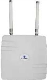 | Bridge/Access Point | 2.4G, 5G (AP) |
| EW75000-08 | 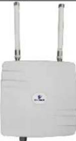 | Access Point | 5G (AP) |
| EW75000-13 |  | Bridge/Subscriber unit | 5G (Subscriber) |
2 Installation
Unpacking the Hardware
Unpack the items and confirm that no items are missing or damaged. Your package should include:
• One EW75000 series hardened wireless access point (AP) or subscriber unit
- Zero, two or four omnidirectional antennas, depending on model
- Mounting bracket set
- Grounding wire
- Quick installation guide
If any item is damaged or missing, notify your authorized EtherWAN representative. Keep the carton, including the original packing material, in case you need to store the product or return it.
Supplying Power
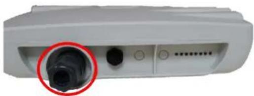
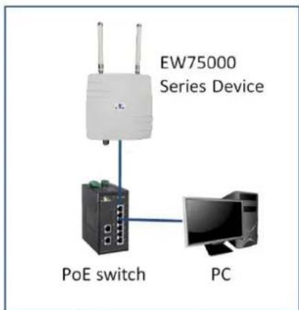
All EW75000 series models are PoE Powered Devices, and have no AC or DC power socket. Power is supplied through an Ethernet cable plugged into the RJ45 port. The cable must be connected to a switch that supports PoE, or an inline power injector. Maximum power consumption is 13 watts.
natural_image
Close-up of a white electronic device with a black connector and a red circle highlighting a detail (no visible text or symbols)RJ-45 PoE Port

Warning: Do not apply power to the device until all supplied antennas have been rarely attached.
Digital Configuration
Use an Ethernet cable to connect a PC to the PoE switch or power injector, and another cable to connect the switch/injector to the EW75000. Use a web browser to navigate to the default IP address, and log in.

Note: The PC being used to configure the EW75000 Series must be on the same subnet as the EW75000. It may be necessary to change the PC's IP address temporarily.
The default IP address is 192.168.1.20
User name is root, no password.
eWAV Series
You have connected to an eWAV system. Unauthorized access is prohibited. All activities performed on this device are logged and monitored.
Login:
Login: root
Password:
Login
If you need to reset the switch to its default configuration from a remote location, you will need to log in with full administrator rights.
Login: administrator Password: eWAV750o0!
It is highly recommended to change both the root and administrator passwords before putting the device into regular service.
The Quick Set page will display by default. Select the function mode from the drop-down menu in the upper right corner. The fields displayed depend on the mode selected. Alternatively, you can exit the Quick Set page by clicking the "Advanced Mode" tab in the upper right corner, and going directly to the main screen. See chapter on configuration for details.
Connect Antennas
The EW75000 is equipped with an internal directional antenna, which provides long-distance coverage in the direction it is pointing.
Depending on the model, your AP might come with two 5 GHz and/or two 2.4GHz antennas. Screw the antennas into the corresponding threaded sockets in the housing.
Physical Installation

NOTE: It is recommended to test all wireless devices before final installation. This includes bench testing, and signal testing of the AP and subscriber unit in the positions where they will be mounted. Loosely mount AP and subscriber units in the intended installation spots, and ensure that the transmission signal is strong enough for the intended application.
This product is designed for outdoor installation on a pole or wall. It is recommended to install the AP at a height of at least 5 meters (15 feet). Make sure that there are no obstacles between devices. Mount the AP with the Ethernet port and LED facing down.

A higher mounting position will result in a stronger signal.
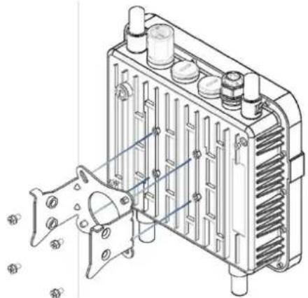
Align the four holes on the housing bracket with those on the back face of the housing, and use the four M5 hex screws to attach the bracket to the housing.
natural_image
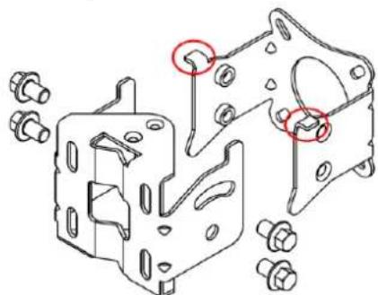
Technical line drawing of an electrical component with slots and connectors (no text or symbols)Attach the two brackets with the supplied M8 hex screws as shown in figure below. Make sure the stop tabs (indicated by red circles in figure) are on the same side as the arc-shaped slot.
natural_image
Technical line drawing of a mechanical bracket assembly with bolt holes and mounting flanges (no text or symbols)Pole mounting:
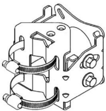
Slide the two ring clamps into the four vertical slots on the bracket. Wrap the clamps around the pole, and tighten the side screws so that the clamps are securely held on the pole.
natural_image
Technical line drawing of a mechanical component with coiled spring and mounting holes (no text or symbols)Wall mounting:
To mount to a wall, use two L-brackets (not supplied), and secure them to the triangular tabs on the top and bottom of the AP bracket. Make sure the L-brackets used and the wall itself are strong enough to hold the weight of the device.
Grounding
There are two grounding terminals located on the rear of the housing. Attach the supplied grounding wire to the housing at either terminal using a screw (not included), and tighten so that the grounding wire is secure. Attach the other end of the grounding wire to an electrical ground.
Surge Protection
In areas with high incidence of lightning, it is suggested to install surge protection devices on the Ethernet cable, such as the PD1041 hardened surge protection device available from EtherWAN. This will protect the indoor network from damage caused by electrical surges through the data cable. Check your local electrical codes, and contact your EtherWAN representative to find out more.
Note that the omnidirectional antennas that come with some models are equipped with built-in gas discharge tube surge protectors, which can be replaced as needed.
LED Status Indicators
The unit has 8 green LED indicators, located on the bottom of the housing.
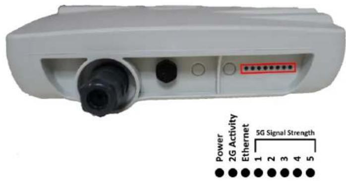
Power: When lit, indicates that device is receiving PoE power.
Ethernet: (Steady on) Indicates the Ethernet port link is up. (Flashing) Indicates data is being transferred.
2.4G: When lit, indicates 2.4G wireless link connected.
5G: Indicates 5G wireless link connected.
➢ LEDs 1 though 5 indicate level of signal strength.
3 Configuration
Quick Set
Once you have logged in, you will see the Quick Set page. This page provides several presets that allow for fast configuration of the device. Selecting an operation mode from the drop-down menu in the upper right corner causes the relevant fields for that setup to be displayed.
If you do not wish to use Quick Set, click the Advanced Mode tab to navigate to the full configuration interface. Refer to the section on Advanced Mode for more information.
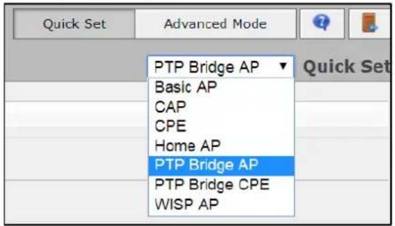
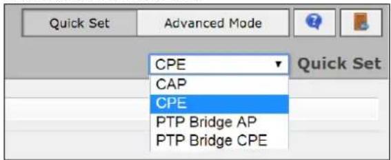
At the top right of the page, select the operation mode. The modes available will depend on whether your device is an access point or a subscriber unit.
Access Point Modes
Subscriber Unit Modes
Description of Quick Set Modes
The Quick Set mode to be selected will depend on the intended application of the EW75000. Each mode is roughly described in the table below.
| MODE | DESCRIPTION |
| CAP | Controlled Access Point, an AP that will be managed by a CAPsMAN server. (CAPsMAN is not supported on all models) |
| CPE | Short for "Customer Premises Equipment", this term is used to mean a "wireless station". As a client device, it connects to a (wireless) network, like your computer would, but doesn't create its own (like an access point). |
| PTP Bridge AP | To transparently interconnect two remote locations together in the same network, set one device to this mode, and the other device to the next (PTP Bridge CPE) mode. |
| PTP Bridge CPE | To transparently interconnect two remote locations together in the same network, set one device to this mode, and the other device to the previous (PTP Bridge AP) mode. |
| WISP AP | Similar to the Home AP mode, but provides more advanced options and uses industry standard terminology, like SSID and WPA. |
| Home AP | This is the default Access Point configuration for most home users. It provides fewer options and simplified terminology. |
| Home AP Dual | Dual band devices (2GHz/5GHz). This is the default Access Point configuration for most home users. It provides fewer options and simplified terminology. |
To create a basic Point to Point link, use the PTP Bridge AP and PTP Bridge CPE Quick Set modes.
Advanced Mode
In Advanced Mode, menu items are arranged on the left side of the page. Items with a small black arrow can be expanded to view its sub-menu. When a menu item is selected, the corresponding layout showing relevant fields and tabs will display in the main working area in the center of the page. Some items in the working area have the following icons to their left:
E - Enable current item
D - Disable current item
- Remove current item
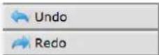
At the bottom of the left-side menu items are undo and redo buttons, which can be used to quickly undo any changes to the configuration.
Also at the bottom, the Hide Passwords button will prevent passwords from displaying on the screen when you enter them in a field.

Description of Menu Items
Wireless
The wireless page allows for the easy management of wireless connections. Functions are organized by tab layers across the top.
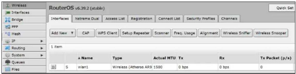
Interfaces – Add, delete and manage wireless interfaces, and analyze interfaces with various tools. Clicking on an item in the table opens the detail page for that wireless interface.
Nstreme Dual – Nstreme Dual is a proprietary wireless protocol compatible only with other eWAV devices. It allows for fast data exchange and more robust channels, in point-to-point and point-to-multipoint setups.
Access List – Used to restrict allowed connections from other devices, and to control connection parameters.
Registration – This is a read-only table that shows information about currently connected clients. It is used only by Access Points.
Connect List – Connect list is an ordered list of rules used to assign priority and security settings to connections with remote access points, and to restrict allowed connections. Each rule in connect-list is attached to specific wireless interface, specified in the interface property of that rule (this is unlike an access list, where rules can apply to all interfaces).
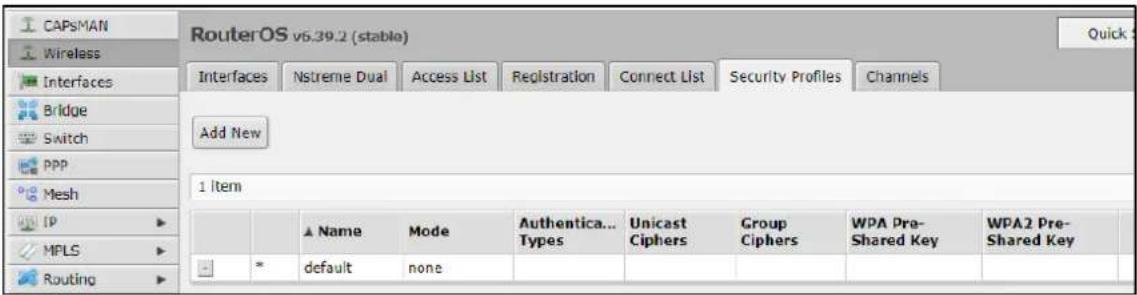
Security Profiles – This page is used to configure security parameters, including RADIUS, EAP, and static keys.
Interfaces
Both physical and virtual interfaces are managed on this page.
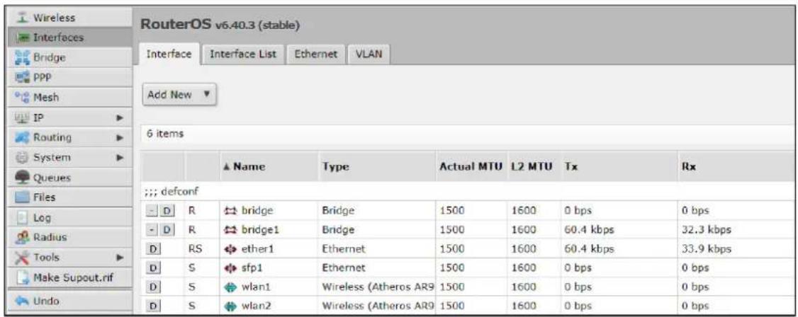
Interface – Shows current interfaces. Clicking on an item in the table opens the detail page for that interface.
Interface List – Allows for the defining of interface sets for easier interface management in firewalls.
Ethernet - Click an Ethernet connection shown in the table to view or modify its parameters.
VLAN – Add new and view existing VLANs. 802.1Q VLANs and Q-in-Q are supported.
Bridge
Ethernet-like networks (Ethernet, Ethernet over IP, IEEE802.11 in ap-bridge or bridge mode, WDS, VLAN) can be connected together using MAC bridges. The bridge feature allows the interconnection of hosts connected to separate LANs (using EoIP, geographically distributed networks can be bridged as well if any kind of IP network interconnection exists between them) as if they were attached to a single LAN. As bridges are transparent, they do not appear in traceroute list, and no utility can make a distinction between a host working in one LAN and a host working in another LAN if these LANs are bridged (depending on the way the LANs are interconnected, latency and data rate between hosts may vary).
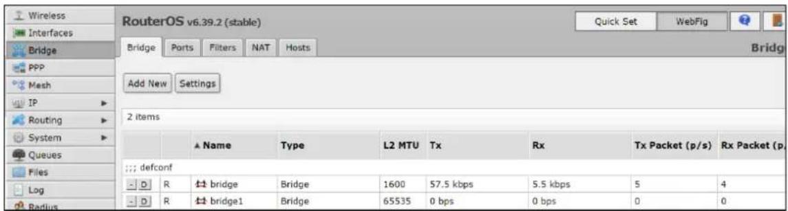
Bridge – In the Bridge sub-tab, new bridges can be created, and existing bridges can be managed.
Ports – This page shows which ports are assigned to which bridges. Click Add New to add a new port to a bridge (Bridge must have already been created).
Filters – The bridge firewall implements packet filtering and thereby provides security functions that are used to manage data flow to, from and through bridge. Filters can be configured with one of three predefined chains:
input: filters packets, where the destination is the bridge (including those packets that will be routed, as they are destined to the bridge MAC address anyway)
output: filters packets, which come from the bridge (including those packets that has been routed normally)
forward: filters packets, which are to be bridged (note: this chain is not applied to the packets that should be routed through the router, just to those that are traversing between the ports of the same bridge)
NAT – Bridge network address translation provides ways for changing source/destination MAC addresses of the packets traversing a bridge. It has two built-in chains:
srcnat: used for "hiding" a host or a network behind a different MAC address. This chain is applied to the packets leaving the router through a bridged interface
dstnat: used for redirecting some packets to other destinations
Hosts – This is a read-only page that shows list of hosts connected to a bridge and their corresponding MAC addresses.
PPP
Point-to-Point Protocol (PPP) is a Layer 2 communications protocol used to establish a direct connection between two nodes. It provides Authentication via the Password Authentication Protocol (PAP), the Challenge-Handshake Authentication Protocol (CHAP), and Microsoft's version (MS-CHAP v1/v2).

Interface – All PPP client and server configurations are added and managed on this page. Click the Add New button and select the desired client or server setup from the drop-down list.
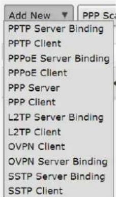
PPPoE Servers – PPPoE is an extension of the standard Point to Point Protocol (PPP). The difference between them is expressed in transport method: PPPoE employs Ethernet instead of serial modem connection.
Secrets – This is the PPP User Database, which stores PPP user access records with PPP user profile assigned to each user.
Profiles – PPP profiles are used to define default values for user access records. Settings in the Secret sub-tab override corresponding profile settings except that single IP addresses always take precedence over IP pools when specified as local-address or remote-address parameters.
Active Connections – This is a read-only page that displays active PPP and PPPoE connections.
L2TP Secrets – L2TP is a secure tunnel protocol for transporting IP traffic using PPP. L2TP encapsulates PPP in virtual lines that run over IP, Frame Relay and other protocols. L2TP incorporates PPP and MPPE (Microsoft Point to Point Encryption) to make encrypted links. The purpose of this protocol is to allow the Layer 2 and PPP endpoints to reside on different devices interconnected by a packet-switched network. With L2TP, a user has a Layer 2 connection to an access concentrator - LAC (e.g., modem bank, ADSL DSLAM, etc.), and the concentrator then tunnels individual PPP frames to the Network Access Server - NAS. This allows the actual processing of PPP packets to be separated from the termination of the Layer 2 circuit. From the user's perspective, there is no functional difference between having the L2 circuit terminate in a NAS directly or using L2TP.
Mesh
The EW75000 series uses HWMP+ for wireless mesh networks. It is based on Hybrid Wireless Mesh Protocol (HWMP) from the IEEE 802.11 draft standard. It can be used instead of (Rapid) Spanning Tree protocols in mesh setups to ensure loop-free optimal routing.
However, the HWMP+ protocol is not compatible with IEEE 802.11 based standard HWMP. Note that the distribution system used for the network does not need to be Wireless Distribution System (WDS). HWMP+ mesh routing supports not only WDS interfaces, but also Ethernet interfaces inside the mesh.

Mesh – Add new and manage existing mesh interfaces on this page. Use the Mesh Traceroute command to determine which paths are being used for routing.
Ports – Add and configure mesh interface ports on this page.
FDB – The FDB (Forwarding Database) page is a read-only page that displays information about local MAC addresses, non-mesh nodes reachable through local interface and direct mesh neighbors.
IP
The IP menu is subdivided into 21 submenus, which can be expanded and collapsed by clicking the small black triangle on the right of the IP button. The function of each submenu item is described below.
ARP
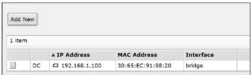
Address Resolution Protocol is used to map OSI level 3 IP addresses to OSI level 2 MAC addresses. The Router has a table of currently used ARP entries. Normally the table is built dynamically, but to increase network security, it can be partially or completely built statically by means of adding static entries.
Accounting
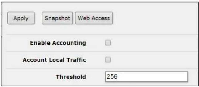
Authentication, Authorization and Accounting feature provides a possibility of local and/or remote (on RADIUS server) Point-to-Point and Hotspot user management and traffic accounting (for all IP traffic passing through the device; local traffic accounting is also an option). For local traffic accounting, the packet source and destination addresses are matched against an IP pair list in the accounting table and the traffic for that pair is increased. The traffic of PPP, PPTP, PPPoE, ISDN and Hotspot clients can be accounted on per-user basis too. Both the number of packets and the number of bytes are accounted. If no matching IP or user pair exists, a new entry will be added to the table.
Addresses
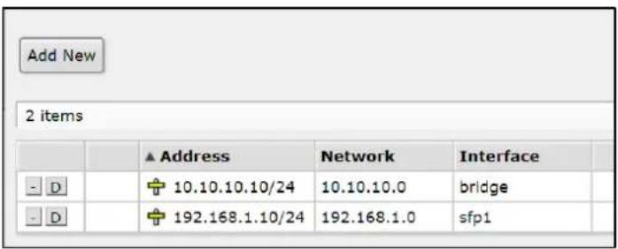
Add and manage IP addresses on this page. It is possible to add multiple IP addresses to an interface or to leave the interface without any addresses assigned to it. In case of bridging or PPPoE connection, the physical interface may not have any address assigned, yet be perfectly usable. Putting an IP address to a physical interface included in a bridge would mean actually putting it on the bridge interface itself.
DHCP Client
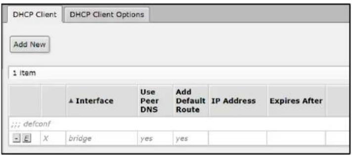
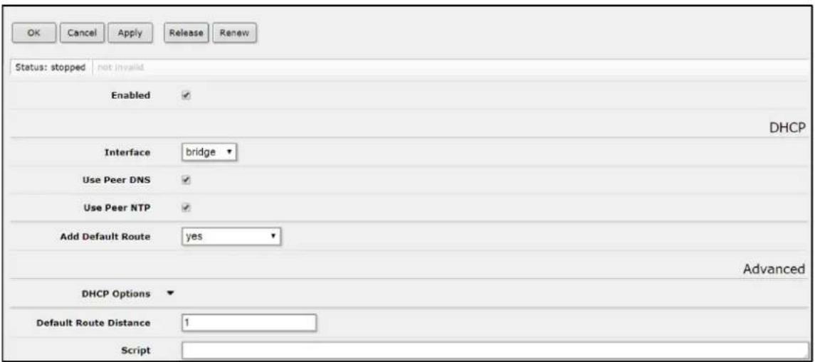
The eWAV DHCP client may be enabled on any Ethernet-like interface at a time. The client will accept an address, netmask, default gateway, and two DNS server addresses. The received IP address will be added to the interface with the respective netmask. The default gateway will be added to the routing table as a dynamic entry. Should the DHCP client be disabled or not renew an address, the dynamic default route will be removed. If there is already a default route installed prior the DHCP client obtains one, the route obtained by the DHCP client would be shown as invalid.
DHCP Relay
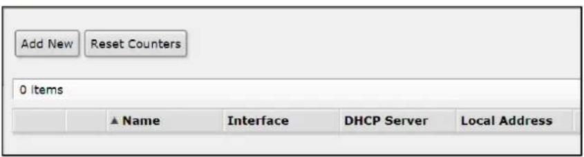
DHCP Relay is a proxy that is able to receive a DHCP request and resend it to the real DHCP server. DHCP relay does not choose a particular DHCP server in the dhcp-server list, it just send the incoming request to all the listed servers.
DHCP Server
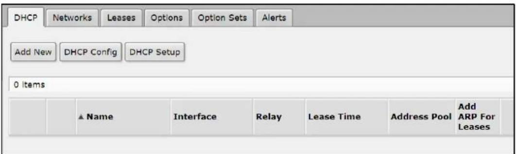
DHCP –The Dynamic Host Configuration Protocol is used for the easy distribution of IP addresses in a network. The eWAV implementation includes both server and client parts
and is compliant with RFC 2131. The eWAV DHCP server supports the basic functions of giving each requesting client an IP address/netmask lease, default gateway, domain name, DNS-server(s) and WINS-server(s) (for Windows clients) information (set up in the DHCP networks submenu). In order for the DHCP server to work, IP pools must also be configured (do not include the DHCP server's own IP address into the pool range) and the DHCP networks. It is also possible to hand out leases for DHCP clients using the RADIUS server.
Networks –The DHCP settings can be specified separately for any IP network defined. Add and manage these settings on this page.
Leases – DHCP server lease tab is used to monitor and manage server's leases. The issued leases are showed here as dynamic entries. You can also add static leases to issue a specific IP address to a particular client (identified by MAC address).
Options – Using the DHCP Option list, it is possible to define additional custom options for DHCP Server to advertise. According to the DHCP protocol, a parameter is returned to the DHCP client only if it requests this parameter, specifying the respective code in DHCP request Parameter-List (code 55) attribute. If the code is not included in Parameter-List attribute, DHCP server will not send it to the DHCP client.
Option Sets – On this page, previously configured options can be grouped into sets for easier implementation.
Alerts – To find any rogue DHCP servers as soon as they appear in the network, the DHCP Alert tool can be used. It will monitor the Ethernet interface for all DHCP replies and check if this reply comes from a valid DHCP server. If a reply from an unknown DHCP server is detected, an alert is triggered.
DNS
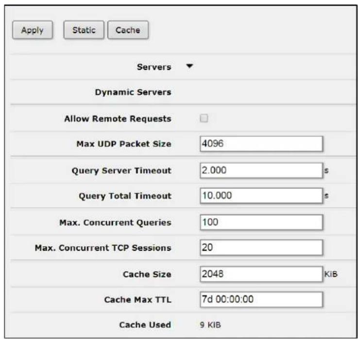
DNS cache is used to minimize DNS requests to an external DNS server as well as to minimize DNS resolution time. This is a simple DNS cache with local items.
Firewall
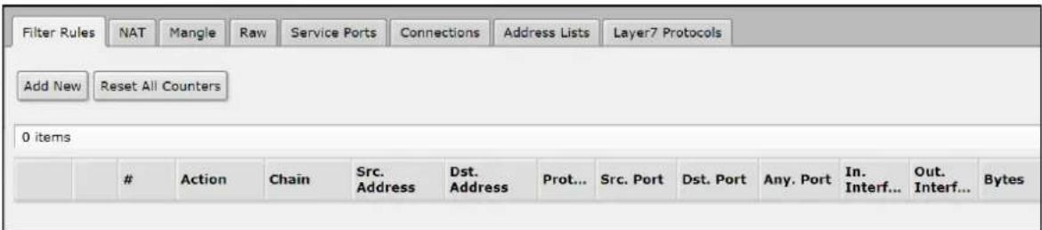
Filter Rules – The firewall operates by means of firewall rules. Each rule consists of two parts - the matcher which matches traffic flow against given conditions and the action which defines what to do with the matched packet. Firewall filtering rules are grouped together in chains. It allows a packet to be matched against one common criterion in one chain, and then passed over for processing against some other common criteria to another chain. For example a packet should be matched against the IP address:port pair.
NAT – Network Address Translation is an Internet standard that allows hosts on local area networks to use one set of IP addresses for internal communications and another set of IP addresses for external communications. A LAN that uses NAT is referred as a natted network. For NAT to function, there should be a NAT gateway in each natted network. The NAT gateway (NAT router) performs IP address rewriting on the way a packet travel from/to LAN.
There are two types of NAT:
source NAT or srcnat. This type of NAT is performed on packets that are originated from a natted network. A NAT router replaces the private source address of an IP packet with a new public IP address as it travels through the router. A reverse operation is applied to the reply packets travelling in the other direction.
destination NAT or dstnat. This type of NAT is performed on packets that are destined to the natted network. It is most commonly used to make hosts on a private network to be accessible from the Internet. A NAT router performing dstnat replaces the destination IP address of an IP packet as it travel through the router towards a private network.
Mangle – Mangle is a kind of 'marker' that marks packets for future processing with special marks. Many other facilities in the EW75000 series make use of these marks, e.g. queue trees, NAT, routing. They identify a packet based on its mark and process it accordingly. The mangle marks exist only within the device - they are not transmitted across the network. Additionally, the mangle facility is used to modify some fields in the IP header, like TOS (DSCP) and TTL fields.
Raw – Firewall RAW table allows for the selective bypassing or dropping of packets before connection tracking, significantly reducing load on the CPU. This tool is very useful for DOS attack mitigation. A RAW table does that does not have matches depends on connection tracking (like connection-state, layer7 etc.). If packet is marked to bypass connection tracking packet de-fragmentation will not occur.
Service Ports – Hosts behind a NAT-enabled router do not have true end-to-end connectivity. Therefore some Internet protocols might not work in scenarios with NAT. To overcome these limitations, the eWAV operating system includes a number of NAT helpers that enable NAT traversal for various protocols.
Connections – View current connections to/from/through the device on this page.
Address Lists – Firewall address lists allow a user to create lists of IP addresses grouped together under a common name. Firewall filter, mangle and NAT facilities can then use those address lists to match packets against them.
Layer7 Protocols – The Layer7 matcher collects the first 10 packets of a connection or the first 2KB of a connection and searches for the pattern in the collected data. If the pattern is not found in the collected data, the matcher stops inspecting further. Allocated
memory is freed and the protocol is considered as unknown. Take into account that a lot of connections will significantly increase memory and CPU usage. To avoid this, add regular firewall matchers to reduce amount of data passed to layer-7 filters repeatedly.
An additional requirement is that the Layer7 matcher must see both directions of traffic (incoming and outgoing). To satisfy this requirement, L7 rules should be set in forward chain. If rule is set in input/prerouting chain then the same rule must be also set in output/postrouting chain, otherwise the collected data may not be complete resulting in an incorrectly matched pattern.
Hotspot

Servers – The simplest way to set up a Hotspot server is by clicking the Hotspot Setup button. The system will ask you to enter the necessary parameters required to successfully set up Hotspot. Afterwards, the default configuration will be added for Hotspot server. Alternatively, you can use the Add New button, and enter the parameters manually.
Server Profiles – This page contains a list of Hotspot server profiles. There may be various different Hotspot systems, defined as Hotspot Server Profiles, on the same gateway machine. One or more interfaces can be grouped into one server profile. There are very few settings for the servers on particular interfaces - most of the configuration is set in the server profiles. For example, it is possible to make completely different set of servlet pages for each server profile, and define different RADIUS servers for authentication.
Users – Client user and password information is added and managed on this page. Additional configuration options for Hotspot users, such as time and data limits, are configured here as well.
User Profiles – The User Profiles page is used for common Hotspot client settings. Profiles are similar to user groups with the same set of settings, rate-limit, filter chain name, etc.
Active – This is a read-only page that displays all current authenticated clients.
Hosts – This is a read-only page that displays all computers connected to the Hotspot server.
IP Bindings – On this page you can set up static One-to-One NAT translations, bypass specific Hotspot clients without authentication, and block specific hosts and subnets from Hotspot network.
Service Ports – Hosts behind a NAT-enabled router do not have true end-to-end connectivity. Therefore some Internet protocols might not work in scenarios with NAT. To overcome these limitations, the eWAV operating system includes a number of NAT helpers that enable NAT traversal for various protocols.
Walled Garden – The Walled Garden page permits authentication bypass settings for HTTP and HTTPS resources.
Walled Garden IP List – This page provides management of Walled-garden IP requests (Winbox, SSH, Telnet, SIP, etc.).
Cookies – This read-only page contains all cookies sent to the Hotspot clients, which are authorized by cookie method.
Neighbors

Neighbors – This read-only page lists all discovered neighbors in the Layer-2 broadcast domain. It shows to which interface neighbor is connected, shows its IP/MAC addresses, and several related parameters.
Discovery Interfaces – Turn discovery protocol on or off for a specific interface or interfaces on this page.
Packing
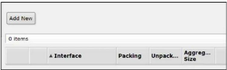
IP Packing provides packet packaging service on network links. It allows simple packet aggregation into larger packets and compression of contents of packets. Packet packing is part of the system package and must have discovery protocol enabled on the interface.
Pools
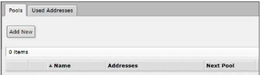
Pools – IP pools are used to define range of IP addresses that is used for DHCP server and Point-to-Point servers.
Used Addresses – This is a read-only page that displays all used IP addresses from IP pools.
Routes
| Routes | Nexthops | Rules | VRF | |||
| Add New | ||||||
| 2 Items | ||||||
| ▲Dst. Address | Gateway | Distance | Routing Mark | Pref. Source | ||
| - | DAC | 10.10.10.0/24 | bridge reachable | 0 | 10.10.10.10 | |
| - | DAC | 192.168.1.0/24 | bridge reachable | 0 | 192.168.1.10 | |
Routes – Add new and view existing IP routes on this page.
Nexthops – Nexthop lookup is a part of the route selection process. This read-only page lists all nexthops that have been established.
Rules – Use this page to set routing rule parameters and actions (drop, lookup, lookup only in table, unreachable).
VRF – Virtual routing and forwarding (VRF) allows multiple instances of a routing table to co-exist within the same device at the same time. This read-only page shows all VRF instances.
SNMP

Simple Network Management Protocol (SNMP) is an Internet-standard protocol for managing devices on IP networks. Enable SNMP and configure general settings on the main page, then click Apply.
Communities – This page allows for the setting up of access rights for SNMP data.
Services
| 8 Items | ||||||
| ▲ Name | Port | Available From | Certificate | |||
| D | api | 8728 | ||||
| D | api-ssl | 8729 | none | |||
| D | ftp | 21 | ||||
| D | ssh | 22 | ||||
| D | telnet | 23 | ||||
| D | winbox | 8291 | ||||
| D | www | 80 | ||||
| E | X | www-ssl | 443 | none | ||
This page shows the protocols and ports used by various services. Individual services can be selectively enabled or disabled.
Settings
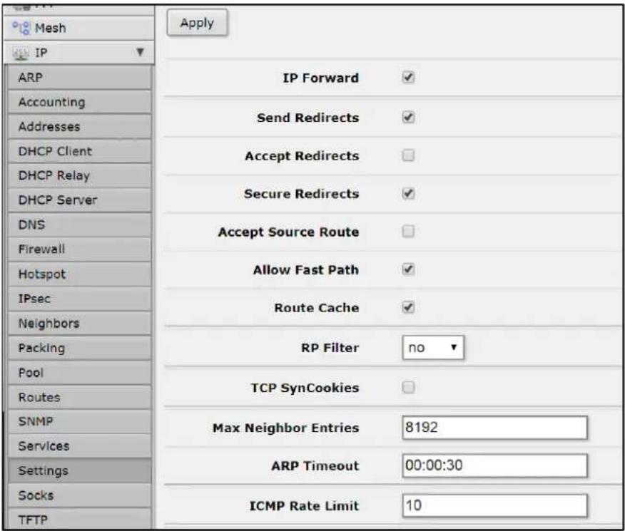
The IP Settings page allows for the configuration of several IP related kernel parameters.
Socks
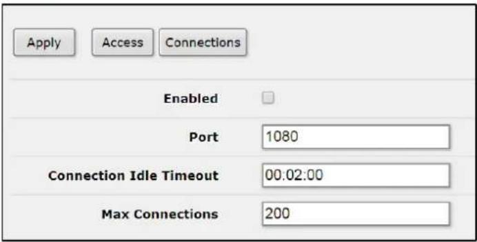
SOCKS is a proxy server that allows TCP based application data to relay across the firewall, even if the firewall would block the packets. The SOCKS protocol is independent from application protocols, so it can be used for many services, e.g., WWW, FTP, TELNET, and others.
At first, an application client connects to the SOCKS proxy server, then the proxy server looks in its access list to see whether the client is permitted to access the remote application resource or not, if it is permitted, the proxy server relies the packet to the application server and creates a connection between the application server and client. Configure your application client to use SOCKS version 4. You should secure the SOCKS proxy using its access list and/or firewall to disallow access from outside. Failing to secure the proxy server may introduce security issues to your network.
TFTP
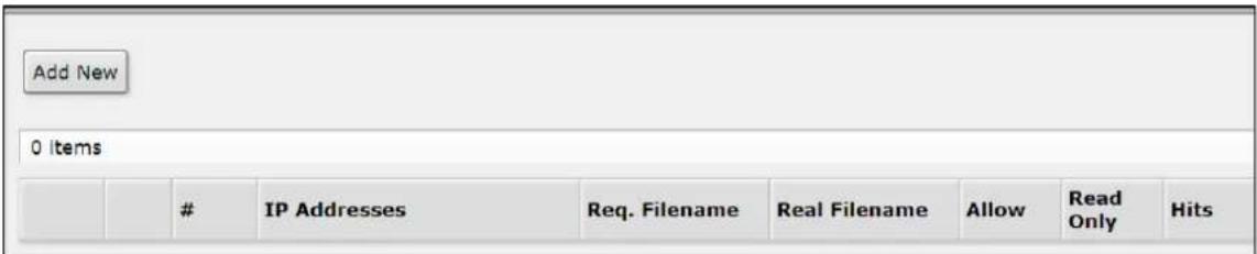
TFTP (Trivial File Transfer Protocol) is a very simple protocol used to transfer files. Each nonterminal packet is acknowledged separately. On this page, you can view existing TFTP access rules, and create new rules. If no rules are visible, then TFTP is not running.
Traffic Flow
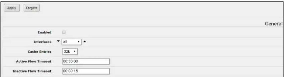
Traffic-Flow is a system that provides statistic information about packets which pass through the device. Besides network monitoring and accounting, system administrators can identify various problems that may occur in the network. With help of Traffic-Flow, it is possible to analyze and optimize the overall network performance. As Traffic-Flow is compatible with Cisco NetFlow, it can be used with various utilities which are designed for Cisco's NetFlow.
Web Proxy
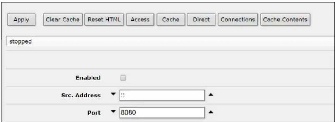
eWAV devices can perform proxying of HTTP and HTTP-proxy (for FTP and HTTP protocols) requests. Proxy server performs Internet object cache function by storing requested Internet objects, i.e., data available via HTTP and FTP protocols on a system positioned closer to the recipient in the form of speeding up customer browsing by delivering them requested file copies from proxy cache at local network speed.
Access – Access lists are configured like a regular firewall rules. Rules are processed from the top to the bottom. First matching rule specifies decision of what to do with this connection. There are a total of 6 classifiers that specify matching constraints. If none of these classifiers is specified, the particular rule will match every connection. If connection is matched by a rule, action property of this rule specifies whether connection will be allowed or not. If the particular connection does not match any rule, it will be allowed. Cache – The cache access list specifies, which requests (domains, servers, pages) have to be cached locally by web proxy, and which not. This list is implemented exactly the same way as web proxy access list. Default action is to cache object (if no matching rule is found).
Direct – If parent-proxy property is specified on the initial page, it is possible to tell the proxy server whether to try to pass the request to the parent proxy or to resolve it connecting to the requested server directly. Direct Access List is managed just like Proxy Access List described in the previous chapter except the action argument. Unlike the access list, the direct proxy access list has default action equal to deny. It takes place when no rules are specified or a particular request did not match any rule.
Connections – This page contains a list of current connections the proxy is serving.
Cache Contents – This page shows cached contents, including file size and access times.
Routing
BFD
Bidirectional Forwarding Detection (BFD) is a low-overhead and short-duration protocol intended to detect faults in the bidirectional path between two forwarding engines, including physical interfaces, sub-interfaces, data link(s), and to the extent possible the forwarding engines themselves, with potentially very low latency. It operates independently of media, data protocols and routing protocols. BFD is basically a hello protocol for checking bidirectional neighbor reachability. It provides sub-second link failure detection support. BFD is not routing protocol specific, unlike protocol hello timers or such. BFD Control packets are transmitted in UDP packets with destination port 3784. Source port is in the range 49152 through 65535. And BFD Echo packets are encapsulated in UDP packet with destination port 3785.
Interfaces - Set and manage BFD timers for an interface
Neighbors - This is a read-only page that displays BDF neighbor status.
OSPF
This device implements OSPF version 2 (RFC 2328). The OSPF protocol is the link-state protocol that takes care of the routes in the dynamic network structure that can employ different paths to its subnetworks. It always chooses shortest path to the subnetwork first. Interfaces – Add and manage OSPF interface parameters on this page, including cost, priority, authentication, authentication key, etc.
Instances – This device supports the running of multiple OSPF instances simultaneously. Note that the OSPF protocol supports two types of metrics:
type1 - OSPF metric is the sum of the internal OSPF cost and the external route cost
type2 - OSPF metric is equal only to the external route cost.
Networks – To start the OSPF protocol, you must define the networks on which OSPF will run and associated area for each of these networks.
Areas – OSPF allows collections of routers to be grouped together. Such a group is called an area. Each area runs a separate copy of the basic link-state routing algorithm. This means that each area has its own link-state database and corresponding shortest path tree. The structure of an area is invisible from other areas. This isolation of knowledge
makes the protocol more scalable if multiple areas are used; routing table calculation takes less CPU resources and routing traffic is reduced. However, multi-area setups create additional complexity. It is not recommended separate areas with fewer than 50 routers. The maximum number of routers in one area is mostly dependent on CPU power you have for routing table calculation.
Area ranges – Prefix ranges are used to aggregate routing information on area boundaries. By default, ABR creates a summary LSA for each route in specific area, and advertises it in adjacent areas. Using ranges allows to create only one summary LSA for multiple routes and send only single advertisement into adjacent areas, or to suppress advertisements altogether. If a range is configured with 'advertise' parameter, a single summary LSA is advertised for each range if there are any routes under the range in the specific area. Else ('advertise' parameter disabled) no summary LSAs are created and advertised outside area boundaries at all.
Virtual Links – As stated in OSPF RFC, the backbone area must be contiguous. However, it is possible to define areas in such a way that the backbone is no longer contiguous. In this case the system administrator must restore backbone connectivity by configuring virtual links. Virtual links can be configured between two routers through a common area called transit area; one of them should have to be connected with the backbone. Virtual links belong to the backbone. The protocol treats two routers joined by a virtual link as if they were connected by an unnumbered point-to-point network.
Neighbors – Read-only page that shows OSPF neighbors.
NMBA Neighbors – Configuration page for non-broadcast multi-access neighbors.
Required only if interfaces with network-type=nbma are configured.
Sham Links – A sham-link is required between any two VPN sites that belong to the same OSPF area and share an OSPF backdoor link. If there is no intra-area link between the CE routers, you do not need to configure an OSPF sham link.
LSA – Read-only page showing link state announcements.
Routes – Read-only page showing OSPF determined routes.
Area Border Routers – Read-only page showing area border routers.
Prefix Lists
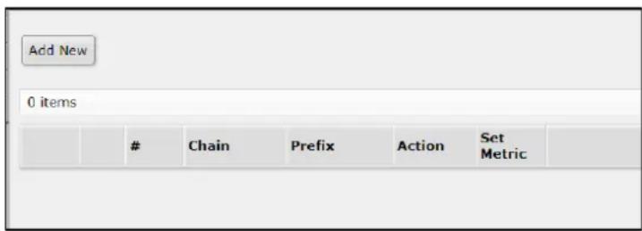
Filtering by prefix list involves matching the prefixes of routes with those listed in the prefix list. When there is a match, the rule is used. Prefix lists can be used to filter out RIP routes, and are used if specified on the RIP menu page.
RIP
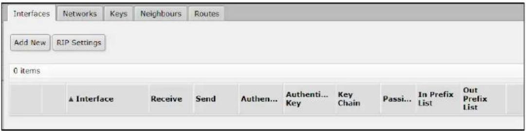
This device supports implements RIP Version 1 (RFC 1058) and Version 2 (RFC 2453). RIP enables routers in an autonomous system to exchange routing information. It always uses the best path (the path with the fewest number of hops (i.e. routers)) available.
Interfaces – Add and manage RIP interface parameters on this page, including version, authentication, prefix lists, etc.
Networks – To start the RIP protocol, the networks on which RIP will run must be defined. Keys – Add and manage MD5 authentication key chains.
Neighbors – This submenu is used to define neighboring routers to exchange routing information with. Normally there is no need to add the neighbors, if multicasting is working properly within the network. If there are problems with exchanging routing information, neighbor routers can be added to the list. It will force the router to exchange the routing information with the neighbor using regular unicast packets.
Routes – This read-only page shows current RIP routes.
System
Clock
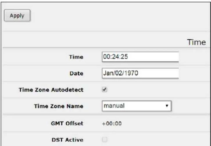
Set time, date, and time zone on this page. If Time Zone Name is set to Manual, then you must enter the time zone and daylight savings information in the four fields at the bottom of the page. If Time Zone AutoDetect is checked, the device will detect the local time zone based on the public IP address.
Health
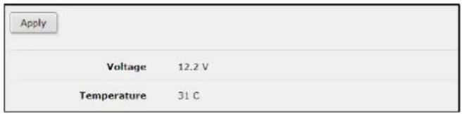
Read-only page that shows history of system actions.
History

Read-only page that shows history of system actions.
Identity
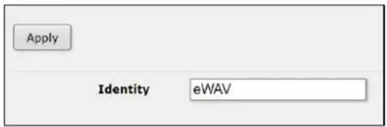
Setting the System's Identity (max. length of 64 characters) provides a unique identifying name for when the system identifies itself to other routers in the network and when accessing services such as DHCP, Neighbor Discovery and default wireless SSID.
Logging
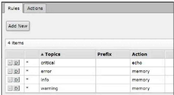
eWAV devices are capable of logging various system events and status information. Logs can be saved in routers memory (RAM), disk, file, sent by email or even sent to remote syslog server.
Rules – On the Rules page, define the topic (account, bfd, caps, ddns, dns, error, gsm, info, iscsi, l2tp, manager, ntp, packet, pppoe, radvd, rip, script, smb, sstp, system, timer, vrrp, web-proxy, async, bgp, certificate, debug, dude, event, hotspot, interface, isdn, ldp,
mme, ospf, pim, pptp, raw, route, sertcp, snmp, state, telephony, upnp, warning, wireless, backup, calc, critical, dhcp, e-mail, firewall, igmp-proxy, ipsec, kvm, lte, mpls, ovpn, ppp, radius, read, rsvp, simulator, ssh, store, tftp, ups, watchdog, write) and the corresponding Action.
Actions – Define the name and type (disk, echo, email, memory, remote).
Password
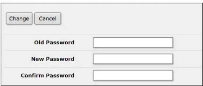
Change the device password for the account currently logged in as.
Reboot
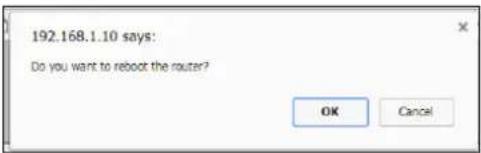
Click this menu item to reboot the device. A confirmation message will display.
Reset Configuration
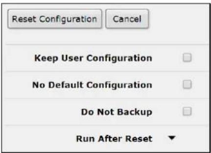
The Reset Configuration button clears all configuration of the router and sets it to the default including the login name and password ('root' and no password), IP addresses and other configuration is erased, interfaces will become disabled. After the reset command is issued the device will reboot.

NOTE: To use the Reset Configuration feature, you must be logged in as administrator.
Resources
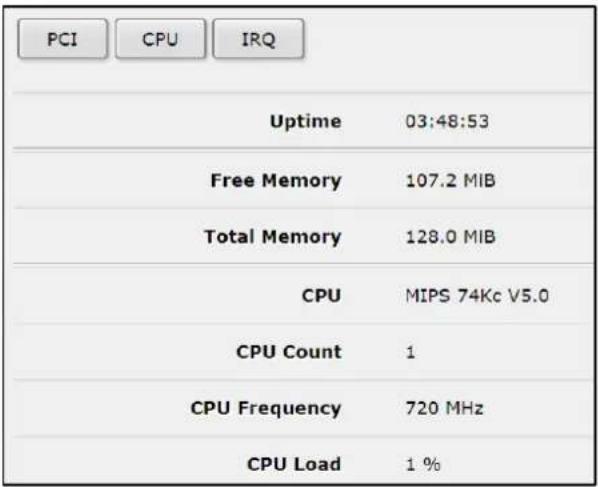
View resource usage for PCI, CPU, and IRQ.
Routerboard
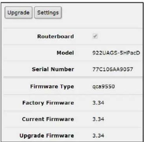
This page provides basic information about the device. The Upgrade button will upgrade the device firmware.
SNTP Client
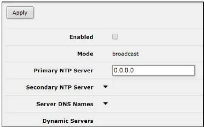
This device implements the SNTP protocol as defined in RFC4330. Manycast mode is not supported.
Users
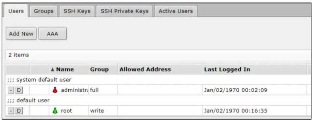
Users – Each user is assigned to a user Group, which defines the rights of the user. In case the user authentication is to be performed using RADIUS, click the AAA button for the configuration page.
Groups –The Group policy is a combination of individual policy items. Groups provide a convenient way to assign different permissions and access rights to different user classes. SSH Keys – Import SSH keys for authentication and associate them with defined users.
SSH Private Keys – Import and list imported private keys. Private keys are used to authenticate remote login attempts using certificates.
Active Users – Read-only page that displays active users.
Watchdog
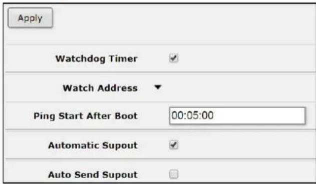
This menu allows for the setting of a system reboot on kernel panic, when an IP address does not respond, or in case the system has locked up. Software watchdog timer is used to provide the last option, so in very rare cases (caused by hardware malfunction) it can lock up by itself.
Queues
Queues are used to limit and prioritize traffic. They can:
- Limit data rate for certain IP addresses, subnets, protocols, ports, and other parameters
- Limit peer-to-peer traffic
- Prioritize some packet flows over others
- Configure traffic bursts for faster web browsing
- Apply different limits based on time
- Share available traffic among users equally, or depending on the load of the channel

Simple Queues – To quickly limit the data rate for specific IP addresses and/or subnets, use simple queues. You can also use simple queues to build advanced QoS applications. Integrated features include:
• Peer-to-peer traffic queuing
- Applying queue rules on chosen time intervals
- Priorities
• Using multiple packet marks from /IP firewall mangle
- Shaping (scheduling) of bidirectional traffic (one limit for the total of upload + download)
Interface Queues – When an Interface Queue is used, data is processed by the queue before being sent over the specified interface. This page lists all available interfaces and allows for the changing of queue type for a particular interface. New interface cannot be added to this list; it is generated automatically.
Queue Tree – Queue tree creates only one directional queue in one of the HTBs (Hierarchical Token Bucket). It is also the only way to add a queue on a separate interface. This eases mangle configuration - you don't need separate marks for download and upload - only upload will get to Public interface and only download will get to Private interface.
Queue Types – This page lists by default created queue types and allows for the adding of new user specific ones.
Files
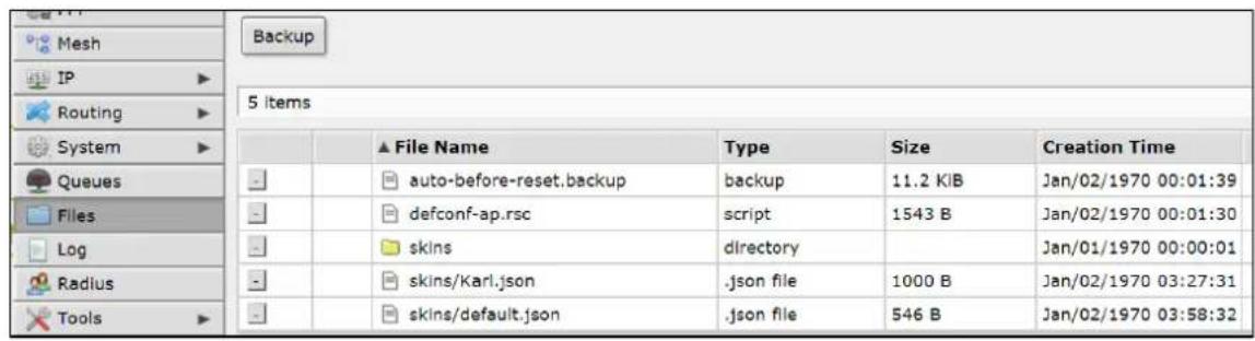
This page shows user space files that are stored on the device. Files can be backed up using the Backup button. Once created, the backup is available in the Files page as a file with the extension .backup.
Log
The device is capable of logging various system events and status information. Logs can be saved in the device's memory (RAM), disk, file, sent by email or even sent to remote syslog server. This page is read-only. Refer to the Logging page for log configuration information.
| 14 items | ||||||
| # | Time | Buffer | Topics | Message | ||
| 0 | Jan/02/1970 00:00:14 | memory | system, error, critical | router was rebooted without proper shutdown | ||
| 1 | Jan/02/1970 00:00:20 | memory | interface, info | ether1 link up (speed 1G, full duplex) | ||
| 2 | Jan/02/1970 00:09:36 | memory | system, info, account | user root logged in from 192.168.1.100 via web | ||
| 3 | Jan/02/1970 03:20:32 | memory | system, info | Item changed by root | ||
| 4 | Jan/02/1970 03:47:30 | memory | system, info, account | user root logged out from 192.168.1.100 via web | ||
Radius
RADIUS, short for Remote Authentication Dial-In User Service, is a remote server that provides authentication and accounting facilities to various network appliances. RADIUS authentication and accounting gives the ISP or network administrator ability to manage PPP user access and accounting from one server throughout a large network. The EW75000 has a RADIUS client which can authenticate for Hotspot, PPP, PPPoE, PPTP, L2TP and ISDN connections. The attributes received from RADIUS server override the ones set in the default profile, but if some parameters are not received they are taken from
the respective default profile. The RADIUS server database is consulted only if no matching user access record is found in router's local database.
Traffic is accounted locally with Traffic Flow and Cisco IP pairs and a snapshot image can be gathered using Syslog utilities. If RADIUS accounting is enabled, accounting information is also sent to the RADIUS server default for that service.
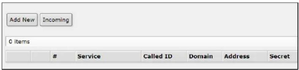
Add New – Enter all parameters for RADIUS client on this page. Note: Microsoft Windows clients send their usernames in form domain\username. You can also remove RADIUS entries on this page.
Incoming – This function supports unsolicited messages sent from RADIUS server. Unsolicited messages extend RADIUS protocol commands, allowing a session to be terminated when it has already been connected to a RADIUS server. For this purpose DM (Disconnect-Messages) are used. Disconnect messages cause a user session to be terminated immediately.
Tools
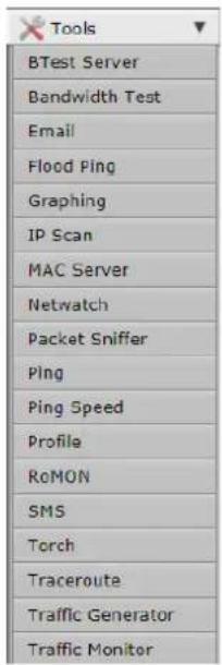
The eWAV web management GUI has a wide range of built-in tools for testing, debugging, and troubleshooting. In addition to classic utilities such as ping, Telnet, and traceroute, the tools menu offers several powerful diagnostic tools with which you may be unfamiliar. It is recommended that you familiarize yourself with these tools when you are working for the first time with an eWAV device.
There are 19 tools in all, and each is briefly described below.
BTest Server
(Bandwidth Test Server)
Used in conjunction with the Bandwidth Test (see below).
Bandwidth Test
The Bandwidth Tester can be used to measure the throughput to another eWAV device (either wired or wireless) and thereby help to discover network "bottlenecks".
The TCP test uses the standard TCP protocol with acknowledgments and follows the TCP algorithm on how many packets to send according to latency, dropped packets, and other features in the TCP algorithm. Please review the TCP protocol for details on its internal speed settings and how to analyze its behavior. Statistics for throughput are calculated using the entire size of the TCP data stream. As acknowledgments are an internal working of TCP, their size and usage of the link are not included in the throughput statistics. Therefore this statistic is not as reliable as the UDP statistic when estimating throughput. The UDP tester sends 110% or more packets than currently reported as received on the other side of the link. To see the maximum throughput of a link, the packet size should be set for the maximum MTU allowed by the links which is usually 1500 bytes. There is no acknowledgment required by UDP; this implementation means that the closest approximation of the throughput can be seen.

NOTE: Bandwidth Test uses a single CPU core, and will reach its limits when core is under 100% load. Bandwidth Test uses all available bandwidth (by default) and will impact network usability.
This utility allows for the sending of emails from the router. This tool can be used to send regular configuration backups and exports to network administrator. Only plain authentication and TLS encryption is used. Other methods are not supported.
Flood Ping
Ping flood sends ICMP (Internet Control Message Protocol) echo requests to a remote host in the same manner as ping, but it sends the next request as soon as it receives a reply.
Graphing
Graphing is a tool to monitor various eWAV parameters over a period of time and display the collected data in attractive graph formats.
IP Scan
IP Scan allows a user to scan the network based on a network prefix or by interface. The tool collects certain data from the network.
MAC Server
This tool is used to configure MAC Telnet, which can allow Telnet access to a router that has no IP address set.
Netwatch
Netwatch monitors state of hosts on the network. It does so by sending ICMP pings to the list of specified IP addresses. For each entry in the Netwatch table you can specify IP address, ping interval and console scripts.
Packet Sniffer
Packet sniffer is a tool that can capture and analyze packets that are going to, leaving or going through the router (except the traffic that passes only through the switch chip).
Ping
Ping uses Internet Control Message Protocol (ICMP) Echo messages to determine if a remote host is active or inactive and to determine the round-trip delay when communicating with it. Ping tool sends ICMP (type 8) message to the host and waits for the ICMP echo-reply (type 0). The interval between these events is called round trip. If the response has not come until the end of the interval, it is assumed that it has timed out. The second significant parameter reported is TTL (Time to Live). It is decremented at each machine in which the packet is processed. The packet will reach its destination only when the TTL is greater than the number of routers between the source and the destination.
Ping Speed
The ICMP Bandwidth Tester (Ping Speed) can be used to approximately evaluate the throughput to any remote computer and thereby help to discover network 'bottlenecks'.
Profile
Profiler tool shows CPU usage for each process running in the eWAV device. It helps to identify which process is using most of the CPU resources.
RoMON
RoMON stands for "Router Management Overlay Network". RoMON works by establishing independent MAC layer peer discovery and data forwarding network. RoMON network operates independently from L2 or L3 forwarding configuration.
Each router on RoMON network is assigned its RoMON ID. RoMON ID can be selected from port MAC address or specified by user. RoMON protocol does not provide encryption services. Encryption is provided at application level by using SSH or other method.
SMS
Used to set up and configure the sending and receiving of SMS messages.
Torch
Torch is real-time traffic monitoring tool that can be used to monitor the traffic flow through an interface. Traffic can be monitored based on protocol name, source address, destination address, port. The tool shows the protocols you have chosen and TX/RX data rate for each of them.

Note: Wireless clients which belong to the same subnet and have enabled default-forwarding communicate through wireless chip. This traffic will not be seen by the torch tool.
Traceroute
Traceroute displays the list of the routers that packet travels through to get to a remote host.
Traffic Generator
Traffic Generator is a tool that allows the user to evaluate performance of DUT (Device Under Test) or SUT (System Under Test). The tool can generate and send RAW packets over specific ports. It also collects latency and jitter values, TX/RX rates, counts lost packets and detects Out-of-Order (OOO) packets. Traffic Generator can be used similar to bandwidth test tool as well as generate packets that will be routed back to packet generator for advanced status collection.
Traffic Monitor
The traffic monitor tool is used to execute console scripts when interface traffic crosses a given threshold. Each item in traffic monitor list consists of its name (which is useful if you want to disable or change properties of this item from another script), some parameters, specifying traffic condition, and the pointer to a script or scheduled event to execute when this condition is met.
Make Supout.rif
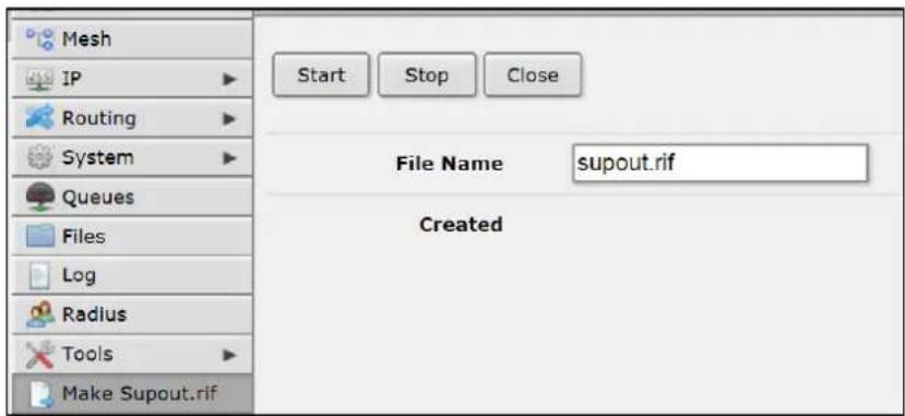
Supout.rif is a support file used for debugging the device and resolving support issues faster. All device information is saved in a binary file, which is stored on the router and can be downloaded from the router using FTP.
Graphs
Graphing is a tool to monitor various interface data over time and view collected data in clear and concise graphs. When you click on the Graphs menu item, a new window will open showing you the available interfaces for which graphs can be viewed. Click on the desired interface, and the graphs will display automatically. Note: You must select the graphs that will be available here by using the Tools → Graphing screen.
Example: Set Up a Point to Point Link Using QuickSet
This section will provide a quick overview on setting up a Point to Point link using the Quick Set screen on the access point and the subscriber unit.
Configure the Access Point
Log into the access point. The Quick Set screen will display by default.
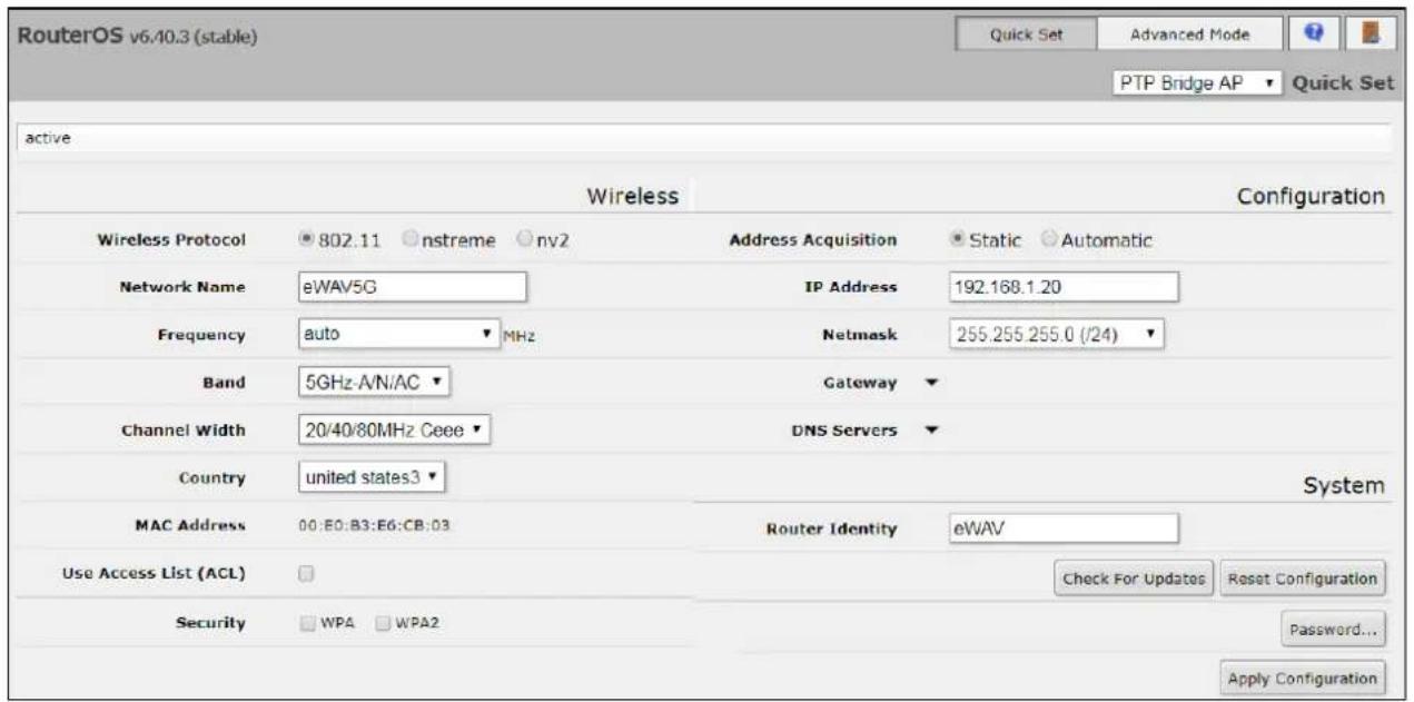
The default IP address is 192.168.1.20. Change the IP address to one that is compatible with your network. Note that it is not necessary to change the IP address of the access point. However you must change the IP of either the access point or the subscriber units, sine the default IP for both devices is the same.
After changing the IP address and clicking Apply Configuration, reconnect to the access point using the new IP you just assigned.
Next, use the drop-down menu in the upper right to set the device mode to PTP Bridge AP. Then click Apply Configuration.
Configure the Subscriber Unit
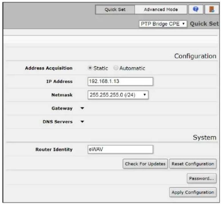
Log into the subscriber unit. On the Quick Set screen, use the drop-down menu in the upper right to set the device mode to PTP Bridge CPE. Then click Apply Configuration.
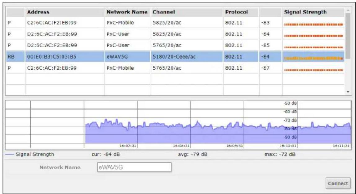
In the lower left of this screen, there is a visual display of wireless networks detected by the EW75000. When the eWAV5G signal appears, click on it and then click the Connect button at the lower right.
line
| Time | Signal Strength (dB) | | -------- | -------------------- | | 16:07:31 | -84 | | 16:08:31 | -79 | | 16:09:31 | -72 | | 16:10:31 | -50 | | 16:11:31 | -60 |The connection will be established, and no further configuration is necessary.
Example: Set Up a Point to Point Link Using Advanced Mode
This section will provide a quick overview on setting up a Point to Point link using the web interface.
Configure the Access Point
Click on the Wireless tab in the menu on the left. All available WLANs will display.
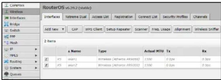
To configure an interface, double-click on the desired WLAN (in this example, wlan1), and the config screen will appear. Click on the Advanced Mode tab at the top. Scroll down to the Wireless section. Set the mode as AP Bridge, and click the E to enable the wireless interface. At this time, you can also set other parameters, such as desired band, wireless protocol, frequency, SSID and the security profile.
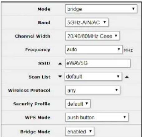
Click Apply and then OK when finished.
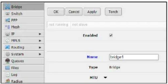
Next, add a bridge by clicking the Bridge tab in the menu on the left, and then clicking Add New, and then OK.
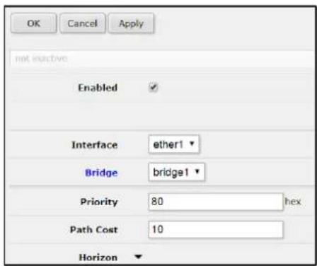
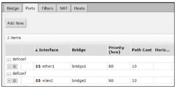
Add ether1 & the wlan used to the bridge port by clicking the Ports tab at the top, and then using the Add New button to add the interfaces to the bridge. Click OK when finished.
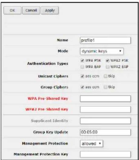
To configure WPA2 security, navigate to the Security Profiles tab of the Wireless page. Make a new profile with the Add button and set the desired WPA2 settings. You can choose this new security profile back in the Interface configuration. Make sure to configure both ends of the link with the same security.
Configure the Subscriber Unit:
Connect to the device and click on the Wireless tab and then wlan1. Set the mode, frequency, SSID, and security profile. Make sure the SSID and the wireless protocol are the same as the one set on the Access Point.
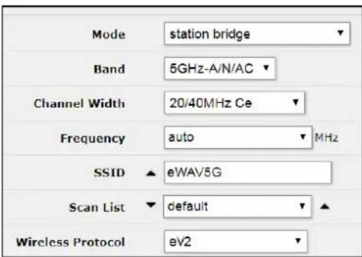
Set the mode to station bridge. Click Apply and then OK when finished.
Specifications
Technology
| Specification | Description |
| Standards | IEEE 802.11IEEE 802.11aIEEE 802.11bIEEE 802.11gIEEE 802.11nIEEE 802.11ac |
| Wireless transmission rate | 5G:11a :108Mbps 11n:300Mbps 11ac: 866Mbps2.4G 11b 22Mbps 11g:108Mbps 11n: 300Mbps |
| Ethernet data rate | Up to 540Mbps (LAN to wireless 11ac) |
Antenna
| Specification | Description |
| EW75200-0804 | 2T2R External Type-N Omni-Antenna 5Ghz 8dBi2T2R External Type-N Omni-Antenna 2.4Ghz 4dBi |
| EW75200-1304 | 2T2R Internal Polarity Panel Antenna 5Ghz 19dBi2T2R Omni-Antenna 2.4Ghz 4dBi |
| EW75000-08 | 2T2R External Type-N Omni-Antenna 5Ghz 8dBi |
| EW75000-13 | 2T2R Internal Polarity Panel Antenna 5Ghz 19dBi |
A.3 Power
| Specification | Description |
| Power consumption | 13 Watts Maximum |
| Power source | PoE in |
Wireless
| Specification | Description | |
| Dual band | EW75200-0804 and EW75200-1304 | |
| Single band | EW75000-08 and EW75000-13 | |
| Frequency range | 5GHz: 5150-5250 MHz and 5725 – 5850 MHz2.4GHz: 2412- 2462 MHz | |
| Channel width | 5GHz: 10MHz, 20MHz, 40MHz, 80MHz2.4GHz: 5MHz, 10MHz, 20MHz, 40MHz | |
| Modulation | 5G: OFDM (BPSK, QPSK, 16-QAM, 64-QAM, 256-QAM)2.4G, 5G: OFDM (BPSK, QPSK,16-QAM, 64-QAM) | |
| RF channels | 2 Non-overlapping | |
| Data security | 256-bit AES-CCM | |
| Transmit power and receive sensitivity 5GHz | ||
| Transmit power (dBm) | Receive sensitivity | |
| 6MBit/s | 31 | -96 |
| 54Mbit/s | 27 | -81 |
| MCS0 | 30 | -96 |
| MCS7 | 27 | -77 |
| MCS9 | 22 | -72 |
| Transmit power and receive sensitivity 2.4GHz | ||
| Transmit power (dBm) | Receive sensitivity | |
| 1MBit/s | 29 | -100 |
| 11Mbit/s | 29 | -94 |
| 6MBit/s | 30 | -96 |
| 54Mbit/s | 27 | -80 |
| MCS0 | 30 | -96 |
| MCS7 | 24 | -79 |
A.5 Physical
| Specification | Description |
| Operating temperature | -40 to 75°C (-40 to 167°F) |
| Environment | Designed for outdoor installation and operation |
| Protection rating | IP67 |
| Housing dimensions | 270 x 270 x 73mm (W x H x D)10.62 x 10.62 x 2.88" |
| Total Device Weight | Small panel 2.5kg (5.5lbs) |
| Installation | Pole / Wall Mounting |
| Connector | 10/100/1000 Ethernet R-45 with waterproof cap |
| 2.4G Omni Antenna | 21 x 220mm (Length x Diameter)(.83 x 8.66") |
| 5G Omni Antenna | 21 x 220mm (Length x Diameter)(.83 x 8.66") |
| 5G Panel Antenna | 371 x 371 x 30mm (W x H x D)14.6 x 14.6 x 1.2" |
Regulatory Approvals
| Specification | Description |
| Address of manufacturer | ul. Terenowa 4252-231 Wroclaw Poland |
| ISO | Manufactured in an ISO 9001 facility |
| FCC | FCC 47 CFR Part 15 Subpart B |
Interference Statement
Federal Communications Commission Interference Statement
FCC, Class A
This product has been tested and found to comply with the limits for a Class A digital device pursuant to Part 15 of the FCC Rules. These limits are designed to provide reasonable protection against harmful interference when the equipment is operated in a commercial environment. This product generates, uses, and can radiate radio frequency energy and, if not installed and used in accordance with the manufacturer's instruction manual, may cause harmful interference with radio communications. Operation of this product in a residential area is likely to cause harmful interference, in which case you will be required to correct the interference at your own expense.
This device complies with Part 15 of the FCC Rules. Operation is subject to the following two conditions:
1) This device may not cause harmful interference.
2) This device must accept any interference received, including interference that may cause undesired operation.
EtherWAN System, Inc.
www.etherwan.com
USA Office
EtherWAN Systems Inc.
2301 E. Winston Road
Anaheim, CA 92806
Tel: (714) 779 3800
Fax: (714) 779 3806
Email: support@etherwan.com
Pacific Rim Office
8F, No.2, Alley 6, Lane 235, Baoqiao Rd.
Xindian District, New Taipei City 231
Taiwan
TEL: +886 -2- 6629-8986
EtherWAN has made a good faith effort to ensure the accuracy of the information in this document and disclaims the implied warranties of merchantability and fitness for a particular purpose, and makes no express warranties, except as may be stated in its written agreement with and for its customers.
EtherWAN shall not be held liable to anyone for any indirect, special or consequential damages due to omissions or errors. The information and specifications in this document are subject to change without notice.
Copyright 2019. All Rights Reserved.
All trademarks and registered trademarks are the property of their respective owners
EW75000 Hardened Wireless LAN Access Point
September 29, 2019
Document version: Version 2
- EtherWAN
- EW75000 Hardened Wireless LAN Access Point
- All Rights Reserved
- Disclaimer of Liability
- Warranty
- Preface
- Audience
- Document Revision Level
- Changes in this Revision
- Document Conventions
- Safety and Warnings
- Abbreviations
- Contents
- Preface......iii
- Contents ...... v
- Introduction....7
- Installation....9
- Configuration 14
- Introduction
- Installation
- Unpacking the Hardware
- Supplying Power
- Digital Configuration
- eWAV Series
- Login: administrator Password: eWAV750o0!
- Connect Antennas
- Physical Installation
- Grounding
- Surge Protection
- LED Status Indicators
- Configuration
- Quick Set
- Access Point Modes
- Subscriber Unit Modes
- Description of Quick Set Modes
- Advanced Mode
- Description of Menu Items
- Wireless
- Interfaces
- Bridge
- PPP
- Mesh
- IP
- ARP
- Accounting
- Addresses
- DHCP Client
- DHCP Relay
- DHCP Server
- Firewall
- Action Chain Src. Address Dst. Address Prot... Src. Port Dst. Port Any. Port In. Interf... Out. Interf... Bytes
- Hotspot
- Neighbors
- Packing
- Pools
- Routes
- SNMP
- Services
- Settings
- Socks
- TFTP
- IP Addresses Req. Filename Real Filename Allow Read Only Hits
- Traffic Flow
- Web Proxy
- Routing
- OSPF
- Prefix Lists
- Chain Prefix Action Set
- RIP
- System
- Clock
- Health
- History
- Identity
- Logging
- Password
- Reboot
- Reset Configuration
- SNTP Client
- Users
- Watchdog
- Queues
- Name Target Upload Max Limit Download Max Limit Packet Marks Total Max Limit (bits/s)
- Files
- Log
- Radius
- Tools
- BTest Server
- Bandwidth Test
- Flood Ping
- Graphing
- IP Scan
- MAC Server
- Netwatch
- Packet Sniffer
- Ping
- Ping Speed
- Profile
- RoMON
- SMS
- Torch
- Traceroute
- Traffic Generator
- Traffic Monitor
- Make Supout.rif
- Graphs
- Example: Set Up a Point to Point Link Using QuickSet
- Configure the Access Point
- Configure the Subscriber Unit
- Example: Set Up a Point to Point Link Using Advanced Mode
- Configure the Subscriber Unit:
- Specifications
- Interference Statement
- Federal Communications Commission Interference Statement
- EtherWAN System, Inc.
- www.etherwan.com
- USA Office
- Pacific Rim Office
Brand : EtherWAN
Model : EW75000
Category : Network card / adapter