TG103H-0802 - Network card / adapter EtherWAN - Free user manual and instructions
Find the device manual for free TG103H-0802 EtherWAN in PDF.


| Product Type | Industrial Media Converter |
| Model | TG103H-0802 |
| Brand | EtherWAN |
| Ethernet Ports | 1 x 10/100/1000Base-T (RJ-45), 1 x 1000Base-X (SFP) |
| Fiber Support | Multi-mode or Single-mode via SFP module |
| Dimensions (L x W x H) | 94 mm x 70 mm x 26 mm |
| Weight | 200 g |
| Power Supply Input | 12–48 VDC |
| Power Consumption | 5 W (max) |
| Operating Temperature | -10°C to 60°C |
| Compliance | IEEE 802.3ab, IEEE 802.3z, IEEE 802.3x |
| Key Functions | Media conversion between copper and fiber, auto-negotiation, auto-MDI/MDIX, link fault pass-through (LFP) |
| LED Indicators | Power, Link/Act (copper and fiber) |
| Mounting | DIN rail mountable |
| Protection | Overload current protection, reverse polarity protection |
| Maintenance and Cleaning | Disconnect power. Clean enclosure with a soft, dry cloth. Do not use liquids or solvents. |
| Safety | Use only with specified power supply. Keep away from water and moisture. Do not disassemble. |
| Spare Parts and Repairability | No user-serviceable parts. Contact EtherWAN support for repair or replacement. |
| General Information | Designed for industrial environments. Plug-and-play installation. |
Frequently Asked Questions - TG103H-0802 EtherWAN
User questions about TG103H-0802 EtherWAN
0 question about this device. Answer the ones you know or ask your own.
Ask a new question about this device
Download the instructions for your Network card / adapter in PDF format for free! Find your manual TG103H-0802 - EtherWAN and take your electronic device back in hand. On this page are published all the documents necessary for the use of your device. TG103H-0802 by EtherWAN.
USER MANUAL TG103H-0802 EtherWAN
Open the carton and unpack the items. Your package should include:
One TG103H Switch
If any items are missing or damaged, notify your EtherWAN representative. If possible, save the carton and packing material in case you need to ship or store the switch in the future.
2 Equipment Needed
- Appropriate cables for data ports. To prevent damage to the switch from electrical surges, it is recommended to use STP (Shielded twisted pair) cabling with a minimum rating of cat5e.
■ Appropriate SFP modules for SFP ports
3 Select a Location
- Installation: Place the device on the DIN rail from above using the slot. Push the front of the device toward the mounting surface until it audibly snaps into place.
- Choose a dry area with an ambient temperature between -40°C to 75°C (-40°F to 167°F).
- Keep away from heat sources, sunlight, warm air exhausts, hot-air vents, and heaters.
- Be sure there is adequate airflow.
- Pollution degree 2.
4 Connect to the Data Ports
The switch has the following ports:
TG103H-0802 8 Gigabit PoE ports + 2 100/1G SFP ports
5 Connect Power
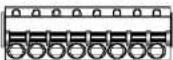
The switch has two power inputs. Only one power input is required to operate the switch. Connect the supply voltage to start up the device via the terminal block.
Power rating:
PoE 30 Watts per port: 52-57 VDC, 5.47-4.99 A
PoE 90 Watts per port: 54-57 VDC, 5.17-4.99 A
- PoE power budget: 270W
- The power input specification complies with the requirements of SELV (Safety Extra Low Voltage), and the power supply should comply with UL 61010-1 and UL 61010-2-201.
Terminal Block
The switch provides two power inputs on a 52-57VDC terminal block.
÷ 1-1+2-2+321
TG103H Page 1
TG103H | Unmanaged PoE Ethernet Switch
| Pin | State | Description |
| Power 1 | + | 52-57VDC |
| - | Power Ground | |
| Power 2 | + | 52-57VDC |
| - | Power Ground | |
| Relay Output Rating | Earth Terminal0.5A @ 48VDC | |
Relay Output Alarm
The switch provides a relay output contact. The relay is used to indicate a user-defined power redundancy failure. The current is 0.5A@48VDC at Normally Open or Normally Closed.
| Relay Contact | ||
| Normally Open | Normally Closed | |
| No power | Open | Closed |
| Normal | Closed | Open |
| Abnormal | Open | Closed |
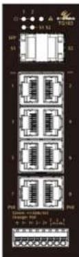
6 LED Indicators
TG103H-0802
| LED | Color | Status |
| L/A (Link/Active) | Green | On: Link activeOff: No linkFlashing: Data transmission |
| PWR 1 & 2 | Green | On: Power onOff: Power off |
Copyright 2023 EtherWAN Systems, Inc. All Rights Reserved 10/3/2023
Installation Guide
| Alarm | Red | On: Error - power redundancy failureOff: No power error condition |
| PoE | Amber | On: Powered Device connectedOff: Powered Device disconnected |
Power-Up Sequence
When the switch is powering up:
• All Link/ACT LEDs blink momentarily.
The Power 1,2 LEDs light up and stay lit.
- LEDs for every port connected to a device will flash, as the switch conducts a brief Power On Self-Test (POST).
7 Quality of Service (QoS)
The QoS feature is automatically activated when the switch is running. Priority mapping is handled according to the following tables:
| CoS priority (802.1p) | 7, 6 | 5, 4 | 3, 2 | 1, 0 |
| DSCP priority | 59, 55 | 47, 46, 43 | 27 | Other |
| Queues | 3 | 2 | 1 | 0 |
| WFQ | Highest Priority | Secondary Priority | 16 | 1 |
EtherNet/IP: UDP 2222 [Queue 2] Profinet Ether type: 0x8892 [Queue 2]
8 DIP Switch Settings
There is a 10-pin DIP switch for enabling the PoE Watchdog function.
When the DIP switch for a port is set to ON, the watchdog function will be enabled after the device has been powered on for 10 minutes to give powered devices time to boot. Every 30 seconds, the device will detect whether the packets from a powered device are being received or not. If no packet is received after 30 seconds, connected ports with the DIP switch set to ON will be restarted (other ports are not disturbed). If a packet is received in the 25th second, then the 30 second interval will be restarted.
If DIP switch 9 (EXT) is set to ON, the watchdog function will be enabled after 5 minutes instead of 10 minutes after the switch powers on.

Each PoE port will calculate the 30 seconds intervals independently, without interfering with other ports. For example, if port 1 is restarted and port 2 is not restarted, the starting times of the counters of the two ports will be different. Note: if watchdog status is toggled for a PoE port with a DIP switch, the device must be restarted for the change to lake effect.
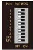
| DIP No. | On | Off |
| 1~8 | Port 1~8 Watchdog Enable | Port 1~8 Watchdog Disable |
| 9 | Set watchdog to run 5 minutes after start | Set watchdog to run 10 minutes after start |
| 10 | Reserved | Reserved |
9 Other Information
DIN-Rail Assembly, Startup, and Dismantling
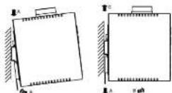
Assembly: Place the switch on the DIN rail from above using the slot. Push the front of the switch toward the mounting surface until it audibly snaps into place. If you install two switch units at the same time, the gap in between the units must be ≥ 2 cm.
- Startup: Connect the supply voltage to start up the Switch via the terminal block.
- Dismantling: Pull out the lower edge and remove the Switch from the DIN rail.

"The device can get hot to the touch after running at full load for some time. Please use caution when handling the device."
Use cable type - AWG 18-22 and corresponding pin type cable terminals.
The rating of the power wire used must be at least 75°C.
Use Copper conductors only.
If the equipment is used in a manner not specified by the manufacturer, the protection provided by the equipment may be impaired.
For repair or maintenance needs, contact EtherWAN directly.

Use a dry cloth to clean the labelling.
If the equipment is used in a manner not specified by the manufacturer, the
protection provided by the equipment may be impaired.
The product is open type, intended to be installed in an industrial control panel or an enclosure.
SFP module specification requirement: Class 1 laser product. Complies with CDRH 21CFR 1040.10 and 1040.11. Rated 3.3 or 5 VDC.
The installation safety of any system incorporating the equipment is the responsibility of the assembler of the system.
Manufacturer Information:
EtherWAN Systems, Inc.
2301 E. Winston Rd., Anaheim, CA 92806, USA
Scan the QR code for more information on the product:
http://www.etherwan.com/us

Brand : EtherWAN
Model : TG103H-0802
Category : Network card / adapter