
UNO-148-B33BA - Industrial computer Advantech - Free user manual and instructions
Find the device manual for free UNO-148-B33BA Advantech in PDF.


| Brand | Advantech |
| Model | UNO-148-B33BA |
| Product type | Embedded industrial PC (automated controller) |
| Main use | Industrial control, data acquisition, automation |
| Power supply | 10 Vdc, 7.7 A (SELV certified source) |
| Approximate dimensions | 200 x 150 x 50 mm |
| Approximate weight | 1.5 kg |
| Storage temperature | -40 °C to 70 °C |
| Use environment | Indoor, non-polluted, without children |
| Internal battery type | Replaceable lithium battery (type CR2032 or equivalent) |
| Maintenance and cleaning | Disconnect before cleaning; use a damp cloth, no detergents |
| Safety | Do not open (non-user-serviceable parts); mandatory grounding |
| Repairability | Return to manufacturer for any repair (except battery) |
| Spare parts available | Internal battery only; other parts not supplied |
| Warranty | Consult the reseller or Advantech |
| Package contents | UNO-148, power cable, documentation (manual) |
Frequently Asked Questions - UNO-148-B33BA Advantech
User questions about UNO-148-B33BA Advantech
0 question about this device. Answer the ones you know or ask your own.
Ask a new question about this device
Download the instructions for your Industrial computer in PDF format for free! Find your manual UNO-148-B33BA - Advantech and take your electronic device back in hand. On this page are published all the documents necessary for the use of your device. UNO-148-B33BA by Advantech.
USER MANUAL UNO-148-B33BA Advantech
natural_image
Line drawing of two electronic devices with internal components, one labeled 'ADVANTROK' (no other text or symbols)UNO-148 Industrial PC
Intel® UP3 Processor Automation Computer, with 3 x LAN, 4 x COM, 3 x USB 3.2 Gen 2, 1 x USB 2.0, 2 x DP 1.4, 8DI/8DO, 1 x mPCIe, 1 x M.2 B-Key, 1 x M.2 M-Key, 1 x M.2 E-Key, 1 x Nano SIM Slot and TPM 2.0
Copyright
The documentation and the software included with this product are copyrighted 2022 by Advantech Co., Ltd. All rights are reserved. Advantech Co., Ltd. reserves the right to make improvements to the products described in this manual at any time without notice. No part of this manual may be reproduced, copied, translated, or transmitted in any form or by any means without the prior written permission of Advantech Co., Ltd. The information provided in this manual is intended to be accurate and reliable. However, Advantech Co., Ltd. assumes no responsibility for its use, nor for any infringements of the rights of third parties that may result from its use.
Acknowledgments
IBM, PC/AT, PS/2, and VGA are trademarks of International Business Machines Corporation.
Intel ^® , Core ^TM and Atom ^TM are trademarks of Intel ^® Corporation.
Microsoft Windows and MS-DOS are registered trademarks of Microsoft Corp.
All other product names or trademarks are properties of their respective owners.
Support
For more information on this and other Advantech products, please visit our website at http://www.advantech.com
For technical support services, please visit our support website at http://support.advantech.com/
This manual applies to the following models. These are abbreviated as UNO-148 products in this article.
*Model name
UNO-148
UNO148B
*Part numbers:
UNO-148-B73BA/UNO-148-B53BA/UNO-148-B33BA
UNO-148-B73BI/UNO-148-B53BI/UNO-148-B33BI
UNO148B73B2101-T UNO148B73B2102-T UNO148B73B2103-T
UNO148B73B2201-T UNO148B73B2202-T UNO148B73B2203-T
UNO148B73B2204-T UNO148B73B2205-T UNO148B73B2206-T
UNO148B73B2207-T UNO148B73B2208-T UNO148B73B2209-T
UNO148B73B2301-T UNO148B73B2302-T UNO148B73B2303-T
UNO148B73B2304-T UNO148B73B2305-T UNO148B73B2306-T
UNO148B73B2307-T UNO148B73B2308-T UNO148B73B2309-T
UNO148B73B2401-T UNO148B73B2402-T UNO148B73B2403-T
UNO148B73B2404-T UNO148B73B2405-T UNO148B73B2406-T
UNO148B73B2501-T UNO148B73B2502-T UNO148B73B2503-T
UNO148B53B2101-T UNO148B53B2102-T UNO148B53B2103-T
UNO148B53B2201-T UNO148B53B2202-T UNO148B53B2203-T
UNO148B53B2204-T UNO148B53B2205-T UNO148B33B2206-T
UNO148B53B2207-T UNO148B53B2208-T UNO148B53B2209-T
| UNO148B53B2301-T UNO148B53B2302-T UNO148B53B2303-T |
| UNO148B53B2304-T UNO148B33B2305-T UNO148B53B2306-T |
| UNO148B53B2307-T UNO148B33B2308-T UNO148B53B2309-T |
| UNO148B53B2401-T UNO148B53B2402-T UNO148B53B2403-T |
| UNO148B53B2404-T UNO148B53B2405-T UNO148B53B2406-T |
| UNO148B53B2501-T UNO148B53B2502-T UNO148B53B2503-T |
| UNO148B33B2101-T UNO148B33B2102-T UNO148B33B2103-T |
| UNO148B33B2201-T UNO148B33B2202-T UNO148B33B2203-T |
| UNO148B33B2204-T UNO148B33B2205-T UNO148B53B2206-T |
| UNO148B33B2207-T UNO148B33B2208-T UNO148B33B2209-T |
| UNO148B33B2301-T UNO148B33B2302-T UNO148B33B2303-T |
| UNO148B33B2304-T UNO148B53B2305-T UNO148B33B2306-T |
| UNO148B33B2307-T UNO148B53B2308-T UNO148B33B2309-T |
| UNO148B33B2401-T UNO148B33B2402-T UNO148B33B2403-T |
| UNO148B33B2404-T UNO148B33B2405-T UNO148B33B2406-T |
| UNO148B33B2501-T UNO148B33B2502-T UNO148B33B2503-T |
Product Warranty (2 years)
Advantech warrants the original purchaser that each of its products will be free from defects in materials and workmanship for two years from the date of purchase.
This warranty does not apply to any products that have been repaired or altered by persons other than repair personnel authorized by Advantech, or products that have been subject to misuse, abuse, accident, or improper installation. Advantech assumes no liability under the terms of this warranty as a consequence of such events.
Because of Advantech's high quality-control standards and rigorous testing, most customers never need to use our repair service. If an Advantech product is defective, it will be repaired or replaced free of charge during the warranty period. For out-of-warranty repairs, customers will be billed according to the cost of replacement materials, service time, and freight. Please consult your dealer for more details.
If you believe your product to be defective, follow the steps outlined below.
- Collect all the information about the problem encountered. (For example, CPU speed, Advantech products used, other hardware and software used, etc.) Note anything abnormal and list any on-screen messages displayed when the problem occurs.
- Call your dealer and describe the problem. Please have your manual, product, and any helpful information readily available.
- If your product is diagnosed as defective, obtain a return merchandise authorization (RMA) number from your dealer. This allows us to process your return more quickly.
- Carefully pack the defective product, a completed Repair and Replacement Order Card, and a proof of purchase date (such as a photocopy of your sales receipt) into a shippable container. Products returned without a proof of purchase date are not eligible for warranty service.
- Write the RMA number clearly on the outside of the package and ship the package prepaid to your dealer.
Declaration of Conformity
CE
This product has passed the CE test for environmental specifications when shielded cables are used for external wiring. We recommend the use of shielded cables. This type of cable is available from Advantech. Please contact your local supplier for ordering information.
Test criteria also include the equipment being operated within an industrial enclosure. In order to protect the product from damage caused by electrostatic discharge (ESD) and EMI leakage, we strongly recommend the use of CE-compliant industrial enclosure products.
FCC Class A
This equipment has been tested and found to comply with the limits for a Class A digital device, pursuant to part 15 of the FCC Rules. These limits are designed to provide reasonable protection against harmful interference when the equipment is operated in a commercial environment. This equipment generates, uses, and can radiate radio frequency energy and, if not installed and used in accordance with the instruction manual, may cause harmful interference to radio communications. Operation of this equipment in a residential area is likely to cause harmful interference. In this event, users are required to correct the interference at their own expense.
甲類資訊技術設備
Technical Support and Assistance
- Visit the Advantech website at www.advantech.com/support to obtain the latest product information.
- Contact your distributor, sales representative, or Advantech's customer service center for technical support if you need additional assistance. Please have the following information ready before calling:
– Product name and serial number
– Description of your peripheral attachments
– Description of your software (operating system, version, application software, etc.)
– A complete description of the problem
– The exact wording of any error messages
Part No. 2003014821 Edition 2
Printed in Taiwan May 2023
Safety Precautions - Static Electricity
Follow these simple precautions to protect yourself from harm and the products from damage.
To avoid electrical shock, always disconnect the power from the PC chassis before manual handling. Do not touch any components on the CPU card or other cards while the PC is powered on.
- Disconnect the power before making any configuration changes. A sudden rush of power after connecting a jumper or installing a card may damage sensitive electronic components.
Safety Instructions
-
Read these safety instructions carefully.
-
Retain this user manual for future reference.
-
Disconnect the equipment from all power outlets before cleaning. Use only a damp cloth. Do not use liquid or spray detergents.
-
For pluggable equipment, the power outlet socket must be located near the equipment and be easily accessible.
-
Protect the equipment from humidity.
-
Place the equipment on a reliable surface during installation. Dropping or letting the equipment fall may cause damage.
-
The openings on the enclosure are for air convection. Protect the equipment from overheating. Do not cover the openings.
-
Ensure that the voltage of the power source is correct before connecting the equipment to a power outlet.
-
Position the power cord away from high-traffic areas. Do not place anything over the power cord.
-
All cautions and warnings on the equipment should be noted.
-
If the equipment is not used for a long time, disconnect it from the power source to avoid damage from transient overvoltage.
-
Never pour liquid into an opening. This may cause fire or electrical shock.
-
Never open the equipment. For safety reasons, the equipment should be opened only by qualified service personnel.
-
If any of the following occurs, have the equipment checked by service personnel:
- The power cord or plug is damaged.
– Liquid has penetrated the equipment.
– The equipment has been exposed to moisture.
- The equipment is malfunctioning, or does not operate according to the user manual.
– The equipment has been dropped and damaged.
– The equipment shows obvious signs of breakage.
-
Do not leave the equipment in an environment with a storage temperature of below -20 ^ ( -4 ^ ) or above 60 ^ ( 140 ^ ) as this may damage the components. The equipment should be kept in a controlled environment.
-
CAUTION: Batteries are at risk of exploding if incorrectly replaced. Replace only with the same or equivalent type as recommended by the manufacturer. Discard used batteries according to the manufacturer's instructions.
-
In accordance with IEC 704-1:1982 specifications, the sound pressure level at the operator's position should not exceed 70 dB (A).
-
This product is intended to be supplied by a UL-certified power supply or DC source with SELV output, rated 10 V_DC , 7.7 A, with a minimum TMA of 40^ . If you need further assistance, please contact Advantech for further information.
- Ensure that the voltage of the power source is correct before connecting the equipment to a power outlet. The power outlet socket should have a grounded connection.
- This equipment is for use in indoor, pollution-free environments.
- This equipment is not suitable for use in locations where children are likely to be present.
- If the equipment is used in a manner not specified by Advantech, the protection provided by the equipment may be impaired.
- The equipment contains no user-serviceable parts. Do not open. Return to the manufacturer for servicing.
- Do not block air ventilation holes.
- This is open-type equipment and should be installed in a suitable enclosure.
DISCLAIMER: These instructions are provided according to IEC 704-1 standards.
Advantech disclaims all responsibility for the accuracy of any statements contained herein.
1.2 Safety Precautions.... 2
1.3 Packing List.... 2
1.4 Hardware Specifications 3
1.4.1 General 3
1.4.2 System Hardware 3
1.4.3 I/O Interfaces 4
1.4.4 Environment....4
1.4.5 Certification.... 4
1.4.6 Extension Kit (Optional) 5
1.5 Dimensions 6
Figure 1.1 UNO-148 Dimensions....6
Figure 1.2 UNO-148 Dimensions (With UNO-148-IS2EA Optional Extension Kit)) 6
Figure 1.3 UNO-148 Dimensions (With UNO-148-ID1EA Optional Extension Kit) .... 7
Figure 1.4 UNO-148 Dimensions (With UNO-148-ID1EA Optional Extension Kit) ....7
Chapter 2 Hardware Functionality......9
2.1 Introduction ...... 10
Figure 2.1 Diagram of Connector Locations on UNO-148 (Top Side)....10
Figure 2.2 Key Component Locations on UNO-148 (Bottom Side) 10
Table 2.1: Key Components, Connectors Onboard.... 11
2.2 External I/O Connector.... 12
2.2.1 UNO-148 Base Unit 12
Figure 2.3 Front Panel of UNO-148.... 12
Figure 2.4 Top View of UNO-148 12
2.2.2 UNO-148 Base Unit with UNO-148-IS2EA Expansion Unit (1 x iDoor and 1 x 2.5" SSD/HDD).... 13
Figure 2.5 Front Panel of UNO-148.... 13
Figure 2.6 Top View of UNO-148 13
2.2.3 UNO-148 Base Unit with UNO-148-ID1EA Expansion Unit (iDoor x 1)....14
Figure 2.7 Front Panel of UNO-148.... 14
Figure 2.8 Top View of UNO-148 14
2.2.4 UNO-148 Base Unit with UNO-148-P11EA Expansion Unit (1 x PCIe x4 expansion).... 15
Figure 2.9 Front Panel of UNO-148.... 15
Figure 2.10 Top View of UNO-148 15
2.2.5 Power Connector 16
2.2.6 LAN: Ethernet Connectors.... 16
2.2.7 USB Connectors 16
2.2.8 Display Connectors.... 16
2.2.9 COM Connector.... 17
Table 2.2: COM Connector Pin Assignments.... 17
2.2.10 Digital Inputs and Outputs.... 18
Figure 2.11 Isolated DI Wet Connection Diagram ..... 19
Figure 2.12 Isolated DI Dry Connection Diagram 19
Figure 2.13 Isolated DO Connection Diagram.... 20
2.3 Internal I/O Connectors and Switches .... 20 Figure 2.14 Locations Internal I/O Connectors/Switches for UNO- 148 .... 20
Table 2.3: Internal Connectors and Jumper Switches.... 21
2.3.1 M.2 Connector 22
2.3.2 mPCIe Connector 22
2.3.3 Nano SIM Slot.... 22
2.4 Others .... 22 Figure 2.15Indicators, Reset Buttons, and Antenna Holes.... 22
2.4.1 LED Indicators 22
2.4.2 Reset Buttons 22
2.4.3 Antenna Hole.... 23
Figure 2.16Diagram of Maximum OD Value for the Antenna Holes 23
Chapter 3 Initial Setup.... 25
3.1 Chassis Grounding .... 26 Figure 3.1 Chassis Grounding Connection.... 26
3.2 Connecting Power.... 26
3.3 Storage Installation (Optional) 27
3.3.1 Installing M.2 2280 NVMe.... 28
3.3.2 Installing the M.2 3042 Module.... 30
3.3.3 Installing the M.2 3052 Module.... 32
3.4 Installing the M.2 2230 Module....33 3.4.1 Installing mPCIe....35
3.5 DIN-Rail Installation 36
3.6 Wireless Module Installation (Optional) 37
3.7 Extension Kit Installation (Optional) .... 38 3.7.1 iDoor and HDD/SSD Storage Extension Kit (UNO-148-IS2EA) . 38 3.7.2 iDoor Extension Kit (UNO-148-ID1EA).... 42 3.7.3 PCIe x4 Expansion (UNO-148-P11EA) .... 46
3.8 Remote Power & Reset Settings 51 Table 3.1: Remote Power/On & Reset Settings 51
3.9 BIOS Setting 51
Appendix A System Settings / Pin Assignments 53
A.1 Power Connector (CN1)....54 Table A.1: Power Connector Pin Assignments....54
A.2 LAN: Ethernet Connector (CN4) 54 Table A.2: Ethernet Connector Pin Assignments 54
A.3 USB Connectors (CN5, CN6) 55
A.3.1 USB 2.0 Connector....55 Table A.3: Connector Pin Assignments....55
A.3.2 USB 3.0 Connector....55 Table A.4: USB 3.0 Connector Pin Assignments....55
A.4 Display Connector (CN2, CN3)....56 Table A.5: DisplayPort Adapter Cable Pin Assignments .... 56
A.5 M.2 Connector (CN15).... 57 Table A.6: M.2 B-Key Connector Pin Assignments .... 57
A.6 mPCIe Connector (MINI1) 58 Table A.7: mPCIe Connector Pin Assignments 58
A.7 COM Port RS232/422/485 Settings .... 59 A.7.1 COM1/COM2 TS232/422/485 Settings (SW1) .... 59 A.7.2 COM3/COM4 RS232/422/485 Settings (SW2).... 59 A.7.3 COM Port RS422/485 Termination Resistor Settings.... 61
A.8 BIOS Update Settings.... 61
A.9 AT/ATX Setting (SW8)....62
A.10 Riser Connector (CN12)....63
Table A.8: Expansion Board to Board Connector Pin Assignments 63
A.11 TPM 2.0 BIOS Settings....64
A.12 CPU Turbo Mode BIOS Settings.... 66
A.13 TDP Power Consumption BIOS Settings.... 68
A.14 Storage RAID Configuration (VMD Setup).... 71
A.15 Dynamic Range Temperature Statement.... 73
Chapter 1
Overview
This chapter outlines specifications for UNO-148.
Introduction
Safety Precautions
Accessories
Hardware Specifications
Dimensions
1.1 Introduction
Advantech's UNO-100 series are DIN-rail integrated controllers that feature a modular design for flexible configuration according to specific usage requirements.
UNO-148 is equipped with an 11th Generation Intel ^ Core ^TM i Processor (standard 1.8 GHz, optional up to 4.4 Ghz) with 8 GB DDR4 RAM, and 3 x LAN, 4 x COM, 3 x USB 3.2 Gen 2, 1 x USB 2.0, 8 x DI, 8 x DO and 2 x DP 1.4. The controller also supports 1 x full size Mini PCIe, 1 x M.2 (B-Key), 1 x M.2 (M-Key), 1 x M.2 (E-Key), and 1 x nano SIM card for convenient expansion that supports Advantech's iDoor technology for integrating additional industrial Fieldbus, wireless communication, I/O, and peripheral modules.
1.2 Safety Precautions
Below are a few safety precautions for preventing injury when making connections. In most cases, users can use a standard cable for connection.
Warning!

Always disconnect the power cord from the chassis before manual handling. Do not connect the chassis while the system power is on. A sudden rush of power can damage sensitive electronic components. Only experienced electronics personnel should open the chassis.
Warning!

Always ground yourself to remove any static electric charge before touching UNO-148. Modern electronic devices are very sensitive to static electric charges. Use a grounding wrist strap at all times. Place all electronic components on a static-dissipative surface or in a static shielded bag.
Caution!

Please refer to the below packing list:
■ UNO-148 (with DIN-rail mount)
■ 2 x 10-pin plug-in block for COM port
■ 1 x 20-pin plug-in block for DIO
■ 1 x 2-pin plug-in for Power
■ 1 x earth-ground cable
Quick Start Guide
Warranty card
If anything is missing or damaged, contact your distributor or sales representative immediately.
1.4 Hardware Specifications
1.4.1 General
| Dimensions (W x D x H) 45 x 140 x 200 mm | |
| Weight (Net) 1.5 kg | |
| Mounting DIN-rail | |
| Power Requirement | 10 - 36VDC |
| Power Consumption | 26 W (typical), 60 W (Max) |
1.4.2 System Hardware
| BIOS AMI UEFI 256 Mbit | |
| Watchdog Timer Programmable 255-level timer interval, from 1 to 255 sec | |
| Hardware Security TPM 2.0 | |
| Processor 11th Gen Intel® CoreTM 1.8 GHz (up to 4.4 GHz) | |
| Memory | 2 Slots, Built-in 8 GB DDR4 3200 MHz (Default 8 GB single slot, max. up to 32 GB per slot) |
| Graphics Engine | Intel® Iris® Xe (Supports i5 & i7 CPU)Intel® UHD Graphics (Supports i3 CPU) |
| Ethernet | 2 x 10/100/1000BASE-T Fast Ethernet (RJ-45)1 x 10/100/1000/2500BASE-T Fast Ethernet (RJ-45) |
| LED Indicators | 1x Power: Green-S0, Orange S3 or S51x RUN: Green-Programmable (PLED)1x BTR: RED-RTC Battery Low |
| Communication | M.2 slot for B-Key and E-Key |
| Storage | 1 x M.2 M-Key 2280 NVMe SSD (PCIe x4 Signal)1 x M.2 B-Key 2242 (SATA Signal) |
| Expansion | 1 x M.2 B-key 3042 or 3052 Module (USB 3.2 Gen 2 Signal)1 x Nano SIM card slot for B-Key use1 x M.2 E-Key 2230 WiFi module (PCIe / USB 2.0 Signal)1 x Mini PCIe (PCIe / USB 2.0 Signal) |
Note! The M.2 B-Key can support either 2242 storage (w/ SATA signal) or 3042/3052 Module (w/ USB signal).

1.4.3 I/O Interfaces
| Serial Ports | 4 x RS-232/422/485 (terminal block), 50 ~115.2 kbps (Isolation Protection: 2500 V_DC ) |
| LAN Ports | 1x Intel® I225 Ethernet Chip1x Intel® I219 Ethernet Chip1x Intel® I210 Ethernet Chip |
| Speed | 2 x 10/100/1000BASE-T Fast Ethernet (RJ-45)1 x 10/100/1000/2500BASE-T Fast Ethernet (RJ-45) |
| USB Ports 3 x USB 3.2 Gen 2, and 1 x USB 2.0 (Type-A) | |
| Isolated DIO | 8-ch digital input, 8-ch digital output (Isolation Protection: 2500 V_DC )Input Voltage (Wet Contact)Logic 0: 10 ~ 30 V_DC Logic 1: 0 ~ 3 V_DC Input Voltage (Dry Contact)Logic 0: Shorted to GNDLogic 1: OpenDigital OutputOutput Voltage: 5 ~ 30 V_DC Output Capability Sink: 500 mA max./channel |
| Displays 2 x DP 1.4, up to 7680x3480 (4K) @ 60Hz | |
| Power Connector 1 x 2 Pin (terminal block) | |
1.4.4 Environment
| Operating Temperature -20 ~ 60 °C (-4 ~ 140 °F) with 0.7 m/s airflow | |
| Storage Temperature - 40 ~ 85 °C (-40 ~ 185 °F) | |
| Relative Humidity 95% RH @ 40 °C / 104 °F, non-condensing | |
| Shock Protection Operating, IEC 60068-2-27, 50G, half sine, 11 ms | |
| Vibration Protection | Operating, IEC 60068-2-64, 4 Grms, random, 5 ~ 500 Hz, 1hr/ axis (SSD)Operating, IEC 60068-2-64, 0.3 Grms, random, 5 ~ 500 Hz, 1hr/axis (HDD) |
1.4.5 Certification
Certification CE, FCC, CB, UL 61010-2-201, BSMI
1.4.6 Extension Kit (Optional)
UNO-148 features a modularized design. Advantech offers an optional 2nd extension kit.
■ UNO-148-ID1EA Expansion unit (iDoor x 1)
| Part number UNO-148-ID1EA | |
| Description | 2nd stack extension kit to support 1 x iDoor on UNO-148-ID1EA |
| Ports 1 x iDoor | |
| Dimensions (W x D x H) | 35 x 140 x 200 mm |
| Weight 0.4 kg | |
■ UNO-148-IS2EA Expansion unit (1 x iDoor and 1 x 2.5"SSD/HDD)
| Part number UNO-148-IS2EA | |
| Description | 2nd stack extension kit to support 1 x iDoor and 1 x 2.5"SSD/HDD storage on UNO-148-IS2EA |
| Ports 1 x iDoor, 1 x 2.5" SSD/HDD | |
| Dimensions (W x D x H) | 35 x 140 x 200 mm |
| Weight 0.8 kg | |
■ UNO-148-P11EA Expansion unit (1 x PCIe x4 expansion)
| Part number UNO-148-P11EA | |
| Description | 2nd stack extension kit to support 1 x PCIe x4 on UNO-148-P11EA |
| Ports 1 x PCIe x4 expansion | |
| Dimensions (W x D x H) | 35 x 140 x 200 mm |
| Weight 0.5 kg | |
Note! 1. When UNO-148-P11EA is installed, the PCIe signals of the mPCIe port and SATA signals of the M.2 B-Key socket are occupied by the expansion kit and cannot be used anymore.
- Because of the power used by PCIe x4, the recommended power input for UNO-148 is 24 V_DC (±20%).

1.5 Dimensions
45 x 140 x 200 mm (W x D x H mm)

Figure 1.1 UNO-148 Dimensions
80 x 140 x 200 mm (W x D x H mm)

Figure 1.2 UNO-148 Dimensions (With UNO-148-IS2EA Optional Extension Kit))
80 x 140 x 200 mm (W x D x H mm)

Figure 1.3 UNO-148 Dimensions (With UNO-148-ID1EA Optional Extension Kit)

Figure 1.4 UNO-148 Dimensions (With UNO-148-ID1EA Optional Extension Kit)
Chapter 2
Hardware
Functionality
This chapter details setup instructions for the hardware functions of the UNO-148. It includes connecting peripherals and indicators.
Introduction
■ External I/O Connectors
Internal I/O Connectors
LED Indicators
Reset Buttons
Antenna Holes
2.1 Introduction
The following diagram shows the locations of the UNO-148 motherboard's key components and internal/external connectors.

Figure 2.1 Diagram of Connector Locations on UNO-148 (Top Side)

Figure 2.2 Key Component Locations on UNO-148 (Bottom Side)
Table 2.1: Key Components, Connectors Onboard
| Category Label Function | |
| External | CN1 Power Connector |
| CN2 DisplayPort Connector | |
| CN3 DisplayPort Connector | |
| CN4 LAN Connector | |
| CN5 LAN Connector | |
| CN6 LAN Connector | |
| CN7 USB 3.0 +2.0 Connector | |
| CN8 USB 3.0 x2 Connector | |
| SW1 Reset Button + Power Button | |
| D55 LED Indicator | |
| CN9 8DI/8DO Terminal Connector | |
| CN10 COM Port Terminal Connector (RS232/422/485) | |
| CN11 COM Port Terminal Connector (RS232/422/485) | |
| Internal | CN12 Riser Connector |
| MINI1 Mini PCIe Connector | |
| CN14 M.2 B-Key for 2242/3042/3052 Connector | |
| CN13 M.2 E-Key for 2230 Connector | |
| CN15 M.2 M-Key for 2280 Connector | |
| DIMM2 Memory Slot | |
| DIMM1 Memory Slot | |
| CPU CPU | |
2.2 External I/O Connector
2.2.1 UNO-148 Base Unit

Figure 2.3 Front Panel of UNO-148

Figure 2.4 Top View of UNO-148
2.2.2 UNO-148 Base Unit with UNO-148-IS2EA Expansion Unit (1 x iDoor and 1 x 2.5" SSD/HDD)

Figure 2.5 Front Panel of UNO-148
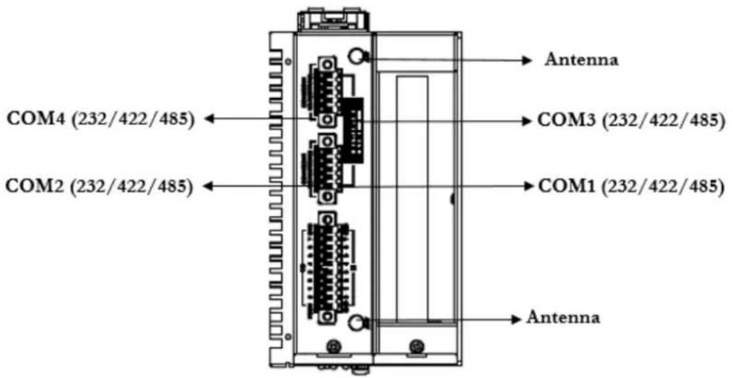
Figure 2.6 Top View of UNO-148
2.2.3 UNO-148 Base Unit with UNO-148-ID1EA Expansion Unit (iDoor x 1)
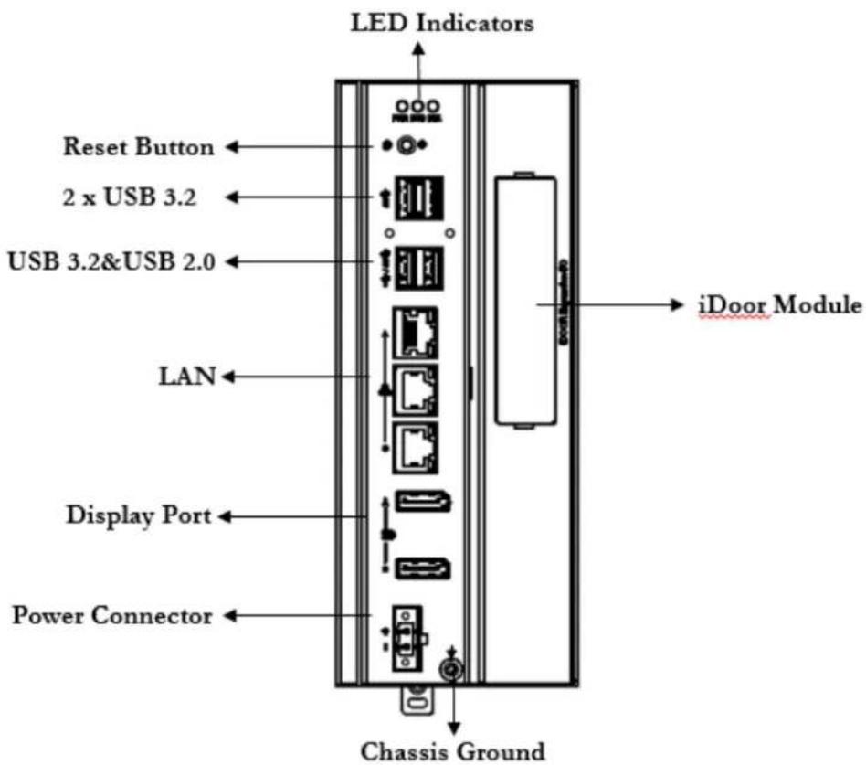
Figure 2.7 Front Panel of UNO-148
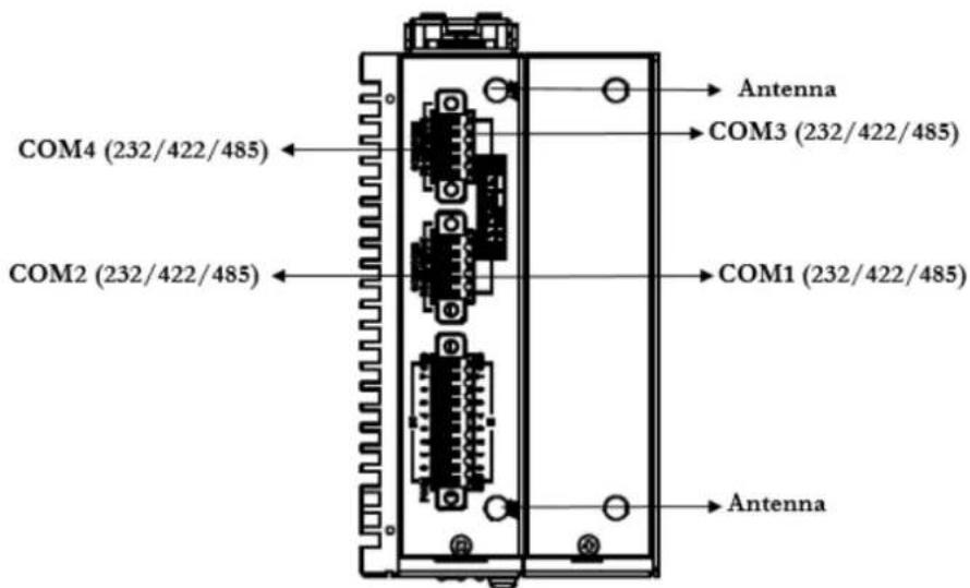
Figure 2.8 Top View of UNO-148
2.2.4 UNO-148 Base Unit with UNO-148-P11EA Expansion Unit (1 x PCIe x4 expansion)

Figure 2.9 Front Panel of UNO-148
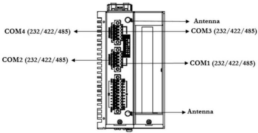
Figure 2.10 Top View of UNO-148
2.2.5 Power Connector
UNO-148 comes with a Phoenix connector that carries 10 - 36 V _DC external power input, and features reversed wiring protection. Therefore, the system will not accrue damage from reversed polarity of ground lines and power lines.
2.2.6 LAN: Ethernet Connectors
UNO-148 is equipped with two Gigabit LAN controllers. An Intel ^® i210/i219/i225 Ethernet controller that complies with IEEE 802.3u 10/100/1000/2500 Base-T is used as the controller chip. The Ethernet port is a standard RJ-45 jack. Additionally, LED indicators are provided on the front of the device to indicate the system's Link (off/green/orange) and Active (green) status.
2.2.7 USB Connectors
UNO-148 features 4 x USB ports that comply with USB EHCI (3 x USB 3.2, 1 x USB 2.0 (Type-A)) specifications. The USB connectors support plug-and-play and hot-swapping functionality for external devices. Additionally, this can be enabled/disabled in the BIOS menu.
2.2.8 Display Connectors
The UNO-148 provides 2 x DP 1.4 connectors for a high-resolution interface up to 7680x3840 @ 60Hz. It also supports DP++ which can be compatible with a passive adapter.
2.2.9 COM Connector
UNO-148 has 4 x COM RS232/422/485 ports of terminal block type. They offer transmission speeds of 50 \~115.2 kbps.
The default mode for both COM ports (COM1&COM2) is RS-232 Mode. Settings can be adjusted via an on-board switch (SW1).

Table 2.2: COM Connector Pin Assignments
| Pin COM1 Mode Signal Name Pin COM2 Mode Signal Name | ||
| 1 | RS232 CTS | RS232 CTS |
| RS422 T- RS422 T- | 2 | |
| RS485 D- RS485 D- | ||
| 3 | RS232 RXD | RS232 RXD |
| RS422 T+ RS422 T+ | 4 | |
| RS485 D+ RS485 D+ | ||
| 5 | RS232 TXD | RS232 TXD |
| RS422 R+ RS422 R+ | 6 | |
| RS485 | RS485 | |
| 7 | RS232 RTS | RS232 RTS |
| RS422 R- RS422 R- | 8 | |
| RS485 | RS485 | |
| 9 | RS232 GND | RS232 GND |
| RS422 GND | RS422GND | |
| RS485 GND | RS485 GND | |
2.2.10 Digital Inputs and Outputs
There are 8 x digital inputs and 8 x digital outputs configured from GPIO pins for on/off triggering and status reading.

The following table indicates the mapping for DIO and GPIO.
| GPIO Pin | Pin 0 | Pin1 | Pin2 | Pin3 |
| DI Pin | DI0 | DI1 | DI2 | DI3 |
| GPIO Pin | Pin 4 | Pin5 | Pin6 | Pin7 |
| DI Pin | DI4 | DI5 | DI6 | DI7 |
| GPIO Pin | Pin 8 | Pin9 | Pin10 | Pin11 |
| DO Pin | DO0 | DO1 | DO2 | DO3 |
| GPIO Pin | Pin 12 | Pin13 | Pin14 | Pin15 |
| DO Pin | DO4 | DO5 | DO6 | DO7 |
And the below table indicates the mapping of DIO and Linux GPIO.
DI point Number DO point Number
| DI0 424 DO0 314 |
| DI1 425 DO1 315 |
| DI2 426 DO2 325 |
| DI3 427 DO3 326 |
| DI4 428 DO4 327 |
| DI5 429 DO5 328 |
| DI6 430 DO6 329 |
| DI7 431 DO7 330 |
Use SW3 to set Wet Contact and Dry Contact for Digital input.

Dry: Configure to Setting 1 (Default)
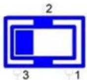
Wet: Configure to Setting 3
Digital Input
■ Input Channels 8
- Input Voltage (Wet Contact), Configure SW3 to Setting 3
- Logic 0: 10 \~ 30 V DC - Logic 1: 0 \~ 3 V DC
- Input Voltage (Dry Contact), Configure SW3 to Setting 1
- Logic 0: Shorted to GND
- Logic 1: Open
■ Isolation Protection 2,500 V DC
■ Over-voltage Protection 30 V DC
■ Opto-Isolator Response 50 μs
Digital Output
■ Output Channels 8
■ Output Voltage: 5 \~ 30 V DC
■ Output Capability Sink: 500 mA max./channel
■ Opto-Isolator Response 50 μs
Isolated Digital Input
Each of the 8 x isolated digital input channels accept voltages from 0 to 30 V. The following figure shows how to connect an external input source to the isolated inputs of UNO-148.
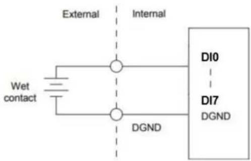
Figure 2.11 Isolated DI Wet Connection Diagram

flowchart
graph TD
    A["Dry Contact"] --> B["External"]
    A --> C["Internal"]
    B --> D["Di0"]
    C --> E["Di7"]
    C --> F["DGND"]
    G["Di0"] --> H["Internal"]
    I["Di7"] --> J["Internal"]
    K["DGND"] --> L["Internal"]
Figure 2.12 Isolated DI Dry Connection Diagram
Isolated Digital Output
If the external voltage source (5 \~ 30 V) is connected to each isolated digital output channel and its isolated digital output turns on (500 mA max./ch), the board's current will sink from the external voltage source. The following figure shows how to connect an external output load to the isolated outputs on UNO-148.

flowchart
graph LR
    A["Isolated Circuit"] --> B["Internal"]
    B --> C["Diode"]
    B --> D["IDO0"]
    B --> E["IDO1"]
    B --> F["IDO2"]
    B --> G["IDO3"]
    B --> H["PGND"]
    C --> I["PCOM"]
    D --> J["PGND"]
    E --> K["PGND"]
    F --> L["PGND"]
    G --> M["PGND"]
    N["Relay"] --> O["VDD"]
    O --> P["5~30V"]
    P --> Q["External"]
Figure 2.13 Isolated DO Connection Diagram
2.3 Internal I/O Connectors and Switches
The following figure demonstrates the locations of internal connectors and switches on the UNO-148 motherboard.

Figure 2.14 Locations Internal I/O Connectors/Switches for UNO-148
Table 2.3: Internal Connectors and Jumper Switches
| Label Function |
| CN19 Internal USB Connector |
| CN12 Riser Connector |
| SW2 COM Port RS232/422/485 settings |
| SW8 AT/ATX/Remote setting |
| MINI1 Mini PCIe Connector |
| SW1 COM Port RS232/422/485 settings |
| CN14 M.2 B-Key for 2242/3042/3052 Connector |
| SW3 DI Setting (Dry/Wet) |
| J3 Clear CMOS Connector |
| CN13 M.2 E-Key for 2230 Connector |
| CN20 iDoor Power Connector |
| CN15 M.2 M-Key for 2280 Connector |
| CN14-1 Nano SIM slot Connector |
| BAT1 RTC Battery Connector |
| SW4 BIOS update Setting |
Note! *This power is from DC Power inputs.

Configure the UNO-148 to match the needs of your application by setting switches. The following details the switch setting definitions:
Dip switch definition:
Bit 1: on

Bit 1: off

2.3.1 M.2 Connector
There is one M.2 B-Key connector for M.2 cards, labeled "CN14" on the board. This M.2 interface is an SATA signal co-lay with a USB signal. It will automatically detect which device you installed and determine the appropriate SATA or USB signal to use. Therefore, it supports the installation of M.2 2242 (w/SATA signal) or 3042/3052 module (w/ USB Signal).
2.3.2 mPCIe Connector
There is one socket for a full-size Mini PCI Express card, labeled "MINI1" on the board. It supports the iDoor module for diversified applications such as isolated COM port, Profibus, WLAN GPRS, LTE, and MRAM. Users can install iDoor easily with the optional extension kit.
2.3.3 Nano SIM Slot
There's one Nano SIM Slot for supporting LTE functionality, labeled "CN14-1" on the board. In addition to installing a SIM card in "CN14-1", users are required to install an LTE Module on "CN14" M.2 B-Key to enable the functionality.
2.4 Others

Figure 2.15 Indicators, Reset Buttons, and Antenna Holes
2.4.1 LED Indicators
Three LEDs indicate the status of the system's power, RTC battery, and programmable LED for user configurations.
■ PWR (Power): Green indicates “normal” and orange indicates “standby”.
■ BTR (RTC Battery): Red indicates a low RTC battery. Check the RTC battery.
■ RUN (Programmable): Users can configure the LED indicator's behavior through GPO signal controls. Green indicates programmed operation.
2.4.2 Reset Buttons
Press the "Reset" button to initiate a hardware reset.
2.4.3 Antenna Hole
This product offers two antenna mounting holes pre-cut for users to install an antenna kit for LTE or wireless functions.
Note! Please be aware of the Maximum OD value of the Antenna Hole when selecting the antenna.


Figure 2.16 Diagram of Maximum OD Value for the Antenna Holes
Chapter 3
Initial Setup
This chapter explains how to Initialize UNO-148.
Chassis Grounding
■ Connecting Power
■ Storage Installation (Optional)
DIN-Rail Installation
■ Wireless Module Installation (Optional)
■ Expansion Module Installation (Optional)
■ Remote Power/On & Reset Setting
BIOS Setting
3.1 Chassis Grounding
UNO-148 provides good EMI protection and a stable grounding base. There is an easy-to-connect chassis grounding point.

Figure 3.1 Chassis Grounding Connection
The earth terminal should use a 16 AWG minimum size green and yellow conductor connector to connect to the earth.
3.2 Connecting Power
This product is intended to be supplied by an approved power adapter or DC power source. This adapter is rated at 10 - 36 V _DC , 7.7-1.31 A and has a maximum tem-
perature of 70 °C (158 °F). If you need further assistance or information, please contact Advantech.
Note!
It is recommended to choose a 150 W adapter when the iDoor expansion module (e.g. PCM-24R2PE) is installed. Recommended PN: 96PSA-A150W24T2-3.

Follow the below instructions:
- Insert the positive and negative wires into the V+ and V- contacts on the terminal block connector.
- Tighten the wire-clamp screws to prevent the DC wires from coming loose.
Take the following guidelines into consideration before wiring the device:
- The terminal block is suitable for 12-24 AWG (12 A). Torque value = 7 lb-in. Use copper conductors only.
- The temperature rating of the input connection cable should be higher than 95 °C (203 °F).

3.3 Storage Installation (Optional)
UNO-148 supports the installation of one M.2 2280 NVMe SSD. The installation is demonstrated in the following steps.
3.3.1 Installing M.2 2280 NVMe
- Remove the 2 screws from the UNO-148 back cover.

natural_image
Line drawing of a server rack with ports and ventilation slots (no text or symbols)- Remove the provided screws from the board.
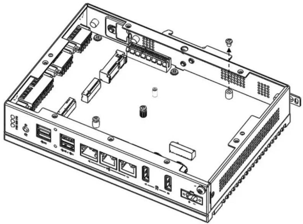
natural_image
Technical line drawing of an internal network device with ports, connectors, and ventilation slots (no text or labels)- Insert the NVMe Card at the "CN15" location. Secure it with the provided screws from Step 2.

natural_image
Technical line drawing of an internal network device with ports, connectors, and ventilation slots (no text or labels)
natural_image
Technical line drawing of an internal network device with ports, connectors, and ventilation slots (no text or labels)3.3.2 Installing the M.2 3042 Module
- Loosen the provided screws on the board. (No need to remove the screws.)
- Use the 3042 bracket from the accessory bag and insert it in the gap underneath where the screw was loosened in Step1.

- Move the 3042 bracket to the center of M.2 and tighten the screws.

natural_image
Technical line drawing of an internal network device with ports, connectors, and ventilation slots (no text or labels)- Remove the provided screw from the 3042 bracket first. Insert the M.2 3042 card and tighten the screw.
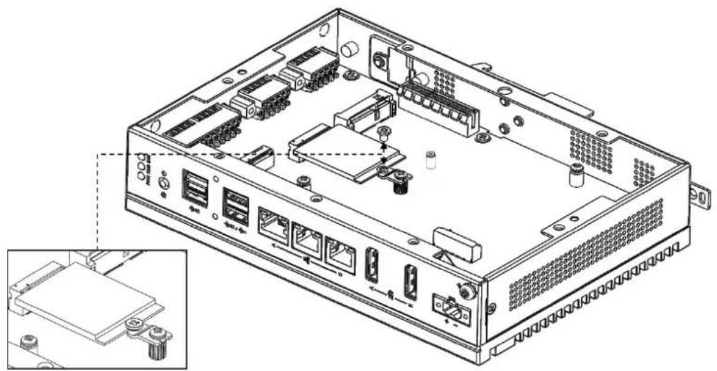
natural_image
Technical line drawing of an internal network device with ports and connectors, showing internal components and a close-up inset (no text or symbols)3.3.3 Installing the M.2 3052 Module
- Remove the provided screws from the board.
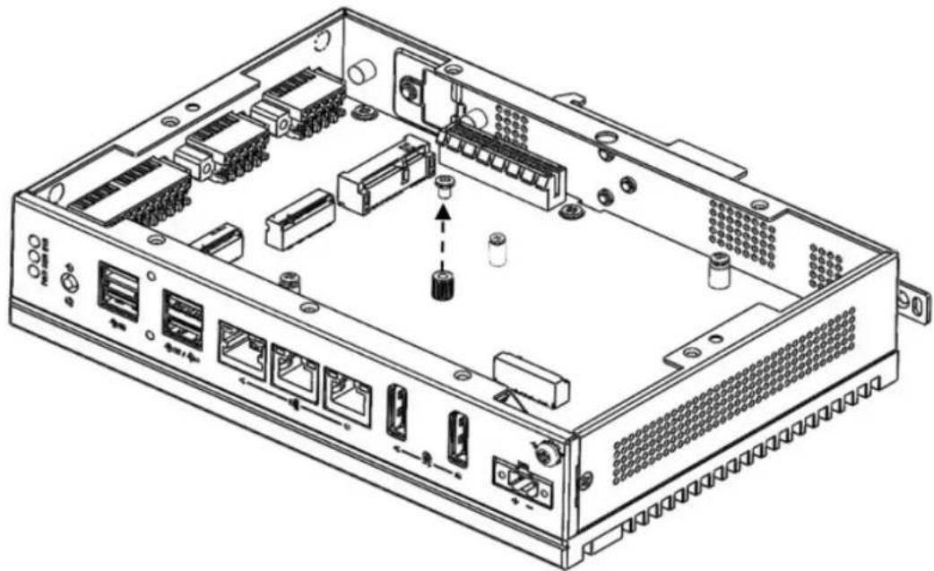
natural_image
Technical line drawing of an internal network device with ports, connectors, and ventilation slots (no text or labels)- Insert the M.2 3052 to the "CN14" location and tighten the screw.
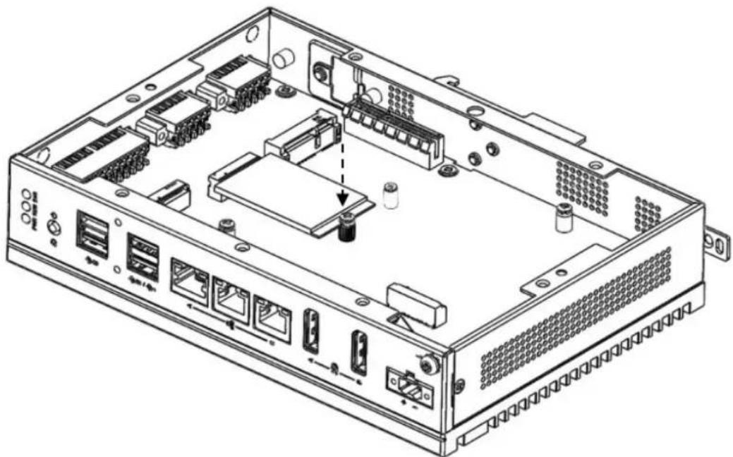
natural_image
Technical line drawing of an internal network device with ports, connectors, and ventilation slots (no text or labels)3.4 Installing the M.2 2230 Module
- Remove the provided screws from the board.
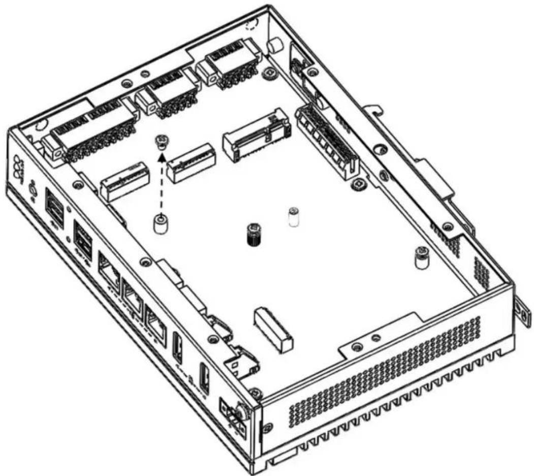
natural_image
Technical line drawing of an internal server rack with visible components and mounting holes (no text or labels)- Insert the M.2 2230 to the "CN13" location and tighten the screw.

natural_image
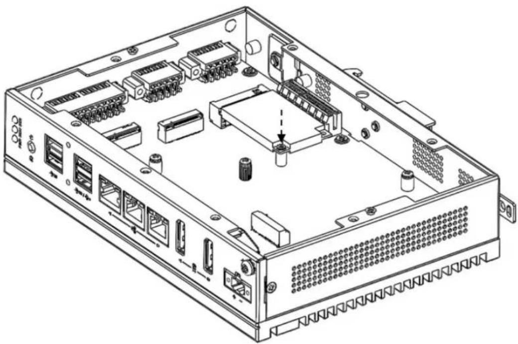
Technical line drawing of an internal server rack with visible components and connectors (no text or labels)3.4.1 Installing mPCIe
- Remove the provided screws from the board.
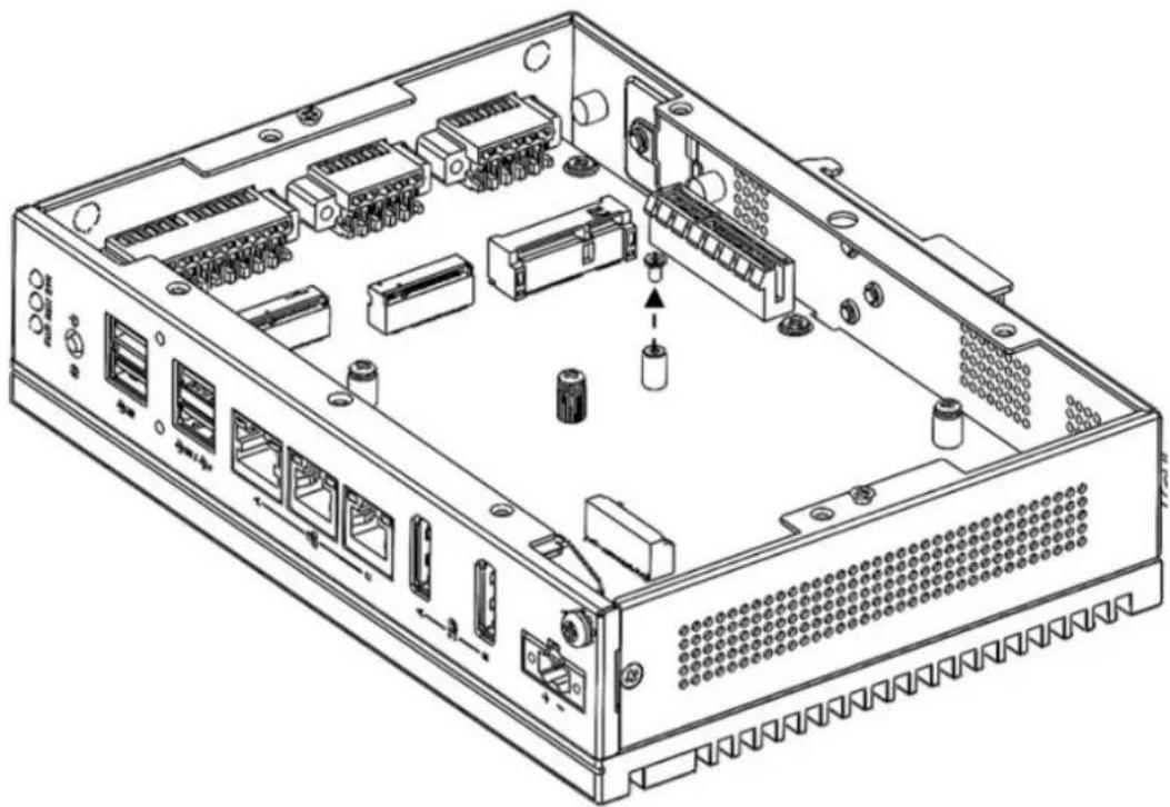
natural_image
Technical line drawing of an internal network device with ports, connectors, and ventilation slots (no text or labels)- Insert the mPCIe to the "MINI1" location and tighten the screw.
natural_image
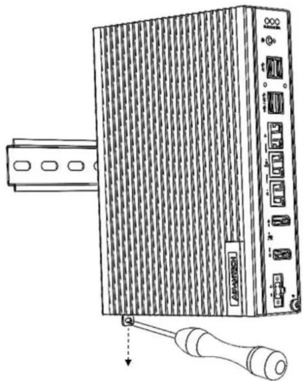
Technical line drawing of an internal network device with ports, connectors, and a central hub (no text or labels)3.5 DIN-Rail Installation
- Install UNO-148 on the rail and secure it to the rail.

- Pull down the "Release Latch" for disassembly using a screwdriver.
natural_image
Line drawing of an electronic device with a cable and connector, no text or symbols present3.6 Wireless Module Installation (Optional)
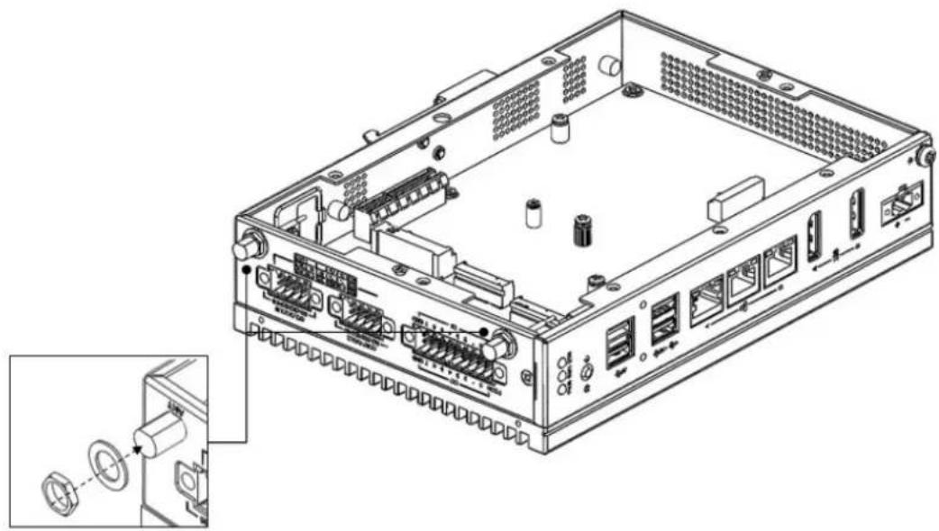
UNO-148 supports a WiFi iDoor/M.2 3042/M.2 3052 module. Follow the steps below for installation:
- Remove the 2 screws from the back cover of the UNO.
- Remove the plugs in the pre-cut antenna hole(s) on the top panel for antenna installation.

natural_image
Technical line drawing of an internal network device with ports and connectors, showing external wiring and a close-up inset (no text or symbols)- Install the SMA connector for the *Antenna cable to the Antenna hole.
- Connect the MHF of the Antenna cable to the module.
- Affix the washers and screw nut.
- Return the back cover and gently screw it into place.
natural_image
Technical line drawing of an internal server rack with ports, connectors, and a close-up inset showing internal components (no text or labels)3.7 Extension Kit Installation (Optional)
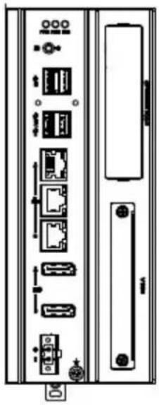
3.7.1 iDoor and HDD/SSD Storage Extension Kit (UNO-148-IS2EA)
You can additionally install a 2nd stacked iDoor and external swappable 2.5" HDD/SSD storage extension kit (PN: UNO-148-IS2EA) on UNO-148 to expand its functionality:
natural_image
Front view of a server rack unit with ports, connectors, and ventilation slots (no text or labels visible)The accessory list for iDoor extension kit (PN: UNO-148-IS2EA)
5 x M3x4L screws for extension kit installation
4 x M3x4L screws for HDD/SSD installation
Follow the steps below for extension kit Installation:
- Remove the 2 x M3x4L screws from the back cover of UNO-148.

natural_image
Technical line drawing of a server rack with ventilation slots and ports (no text or symbols)- Remove the 2 x M3x6L screws from the extension kit.
- Detach the iDoor dummy cover from the iDoor extension kit.
- Loosen the 2 screws holding the SSD/HDD tray and remove the tray.
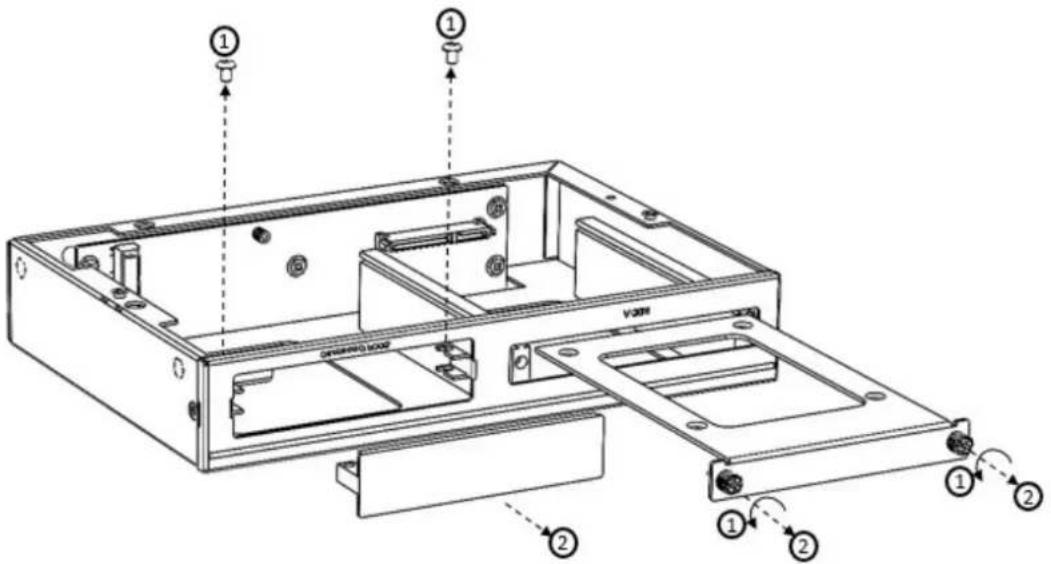
- Attach the 2nd bracket (UNO-148-IS2EA) with 6 x M3x4L screws to the Base Unit (UNO-148).

natural_image
Technical line drawing of a computer chassis with multiple ports and connectors (no text or labels)- Connect the mPCIe connector of the iDoor module onto the board of the UNO-148, and affix it with the 2 x M2x4L screws from the accessory bag of the iDoor extension kit.

- Detach the HDD/SSD bracket from the 2nd stack extension kit, then affix the 2.5" HDD/SSD to the HDD bracket with the 4 x M3x4L screws from the accessory bag of the iDoor extension kit.
- Affix the HDD/SSB bracket back to the extension kit with the provided screws from Step 4.

- Return the back cover and gently screw it into place.

natural_image
Line drawing of a server rack with ventilation grilles and ports (no text or symbols)3.7.2 iDoor Extension Kit (UNO-148-ID1EA)
You can additionally install a 2nd stack iDoor extension kit (PN: UNO-148-ID1EA) on UNO-148 to expand its functionality:

natural_image
Diagram of a server rack cabinet showing internal components and connectors (no text or labels)The accessory list for the iDoor extension kit (PN: UNO-148-ID1EA)
5 x M3x4L screws for extension kit installation
Follow the steps below for extension kit Installation:
- Remove 2 x M3x4L screws from the back cover of UNO-148.

natural_image
Line drawing of a server rack with ventilation grilles and ports (no text or symbols)- Detach the iDoor dummy cover from the iDoor extension kit.
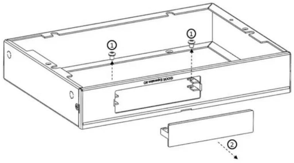
- Attach the 2nd bracket (UNO-148-ID1EA) with 6 x M3x4L screws to the Base Unit (UNO-148).

natural_image
Technical line drawing of a server rack with multiple ports and connectors (no text or symbols)- Connect the mPCIe connector of the iDoor module onto the board of the UNO-148, and affix it with the 2 x M3x4L screws from the accessory bag of the iDoor extension kit.

- Return the back cover and gently screw it into place.
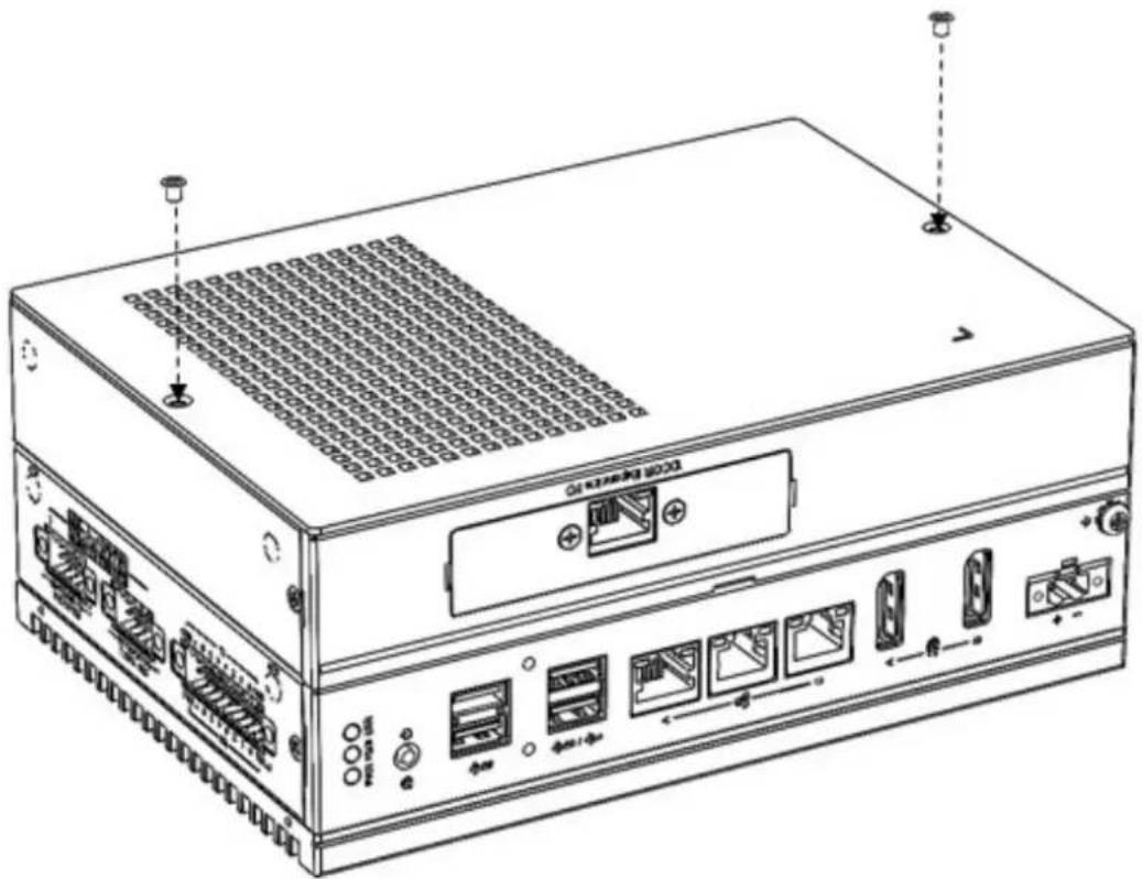
natural_image
Line drawing of a rack-mounted server unit with ports, connectors, and ventilation grilles (no text or symbols)3.7.3 PCIe x4 Expansion (UNO-148-P11EA)
You can additionally install a 2nd stack PCIe x4 expansion kit (PN: UNO-148-P11EA) on UNO-148 to expand its functionality:

The accessory list for the iDoor extension kit (PN: UNO-148-P11EA)
8x M3x4L screws for extension kit installation
Follow the steps below for extension kit Installation:
- Remove the 2 x M3x4L screws from the back cover of UNO-148.

natural_image
Line drawing of a server rack with ventilation slots and ports (no text or symbols)- Attach the 2nd bracket (UNO-148-P11EA) with 6 × M3x4L screws to the Base Unit (UNO-148).

natural_image
Technical line drawing of a server rack with multiple ports and connectors (no text or symbols)- Remove the PCIe cover and PCIe bracket from the 2nd extension kit (UNO-148-P11EA) with 3 x M3x4L screws.

- Install the PCIe card and tighten the screw.

natural_image
Technical line drawing of a computer rack with ports and ventilation slots (no text or labels)- Return the back cover of UNO-148.

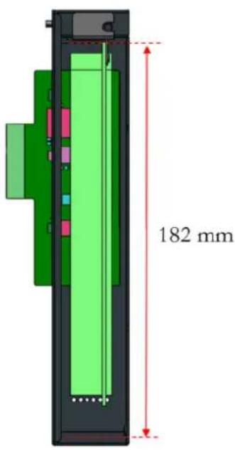
Note! PCIe expansion module dimension limitations.
The maximum length of the PCIe expansion module is 182 mm.


3.8 Remote Power & Reset Settings
UNO-148 supports remote power & reset functions through a DI connector with the switch setting (SW8) on the motherboard. The default setting is for DI6/DI7 functionality. If you want to configure UNO-148 for remote control functions, configure SW8-Bit 2 to "on", then DI6 can be used for remote power settings, and DI7 can be used for remote reset setting.
Table 3.1: Remote Power/On & Reset Settings
SW8 Default 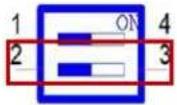 | |
| Description Instruction SW8 | |
| DI function for DI6/DI7 (Default) Bit 2 off | 2 ON 3 |
| Remote Setting Function Bit 2 on | 2 ON 3 |
3.9 BIOS Setting
With the BIOS Setup program, you can modify BIOS settings and control the special features of your computer. The Setup program uses a number of menus for making changes and turning special features on or off.
Press the "ESC" key upon the first boot up to enter the BIOS Setup screen, then, press the "Delete" key during the Power On Self Test (POST) process to enter the BIOS Setup screen, otherwise the system will continue the POST process.
(Please refer to User Manual- Appendix A.11\~A.15 for more settings)
Appendix A
System Settings / Pin Assignments
A.1 Power Connector (CN1)
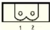
Table A.1: Power Connector Pin Assignments
| Pin | Signal Description |
| 1 Power IN V+ | 10 - 36 V_DC |
| 2 Power IN V- (GND) |
A.2 LAN: Ethernet Connector (CN4)

Table A.2: Ethernet Connector Pin Assignments
| RJ45 Pin Signal Description | |
| 1 MDI0+ | In BASE-T: Media Dependent Interface[0]:2500BASE-T: In MDI configuration, MDI[0]+/- corresponds to BI_DA+/- and in MDI-X configurationMDI[0]+/- corresponds to BI_DB+/-. |
| 2 MDI0- | 10BASE-T and 100BASE-TX: In MDI configuration, MDI[0]+/- is used for the transmit pair and in MDIX configuration MDI[0]+/- is used for the receive pair. |
| 3 MDI1+ | In BASE-T: Media Dependent Interface[1]:2500BASE-T: In MDI configuration, MDI[1]+/- corresponds to BI_DB+/- and in MDI-X configurationMDI[1]+/- corresponds to BI_DA+/-. |
| 6 MDI1- | 10BASE-T and 100BASE-TX: In MDI configuration MDI[1]+/- is used for the receive pair and in MDI-X configuration MDI[1]+/- is used for the transmit pair. |
| 4 MDI2+ | In BASE-T: Media Dependent Interface[3:2]:2500BASE-T: In MDI and in MDI-X configuration, MDI[2]+/- corresponds to BI_DC+/- and MDI[3]+/- corresponds to BI_DD+/-. |
| 5 MDI2- | |
| 7 MDI3+ | 100BASE-TX: Unused. |
| 8 MDI3- | 10BASE-T: Unused. |
Left LED Right LED
| 100/10 Link 1000 Link 2500 Link Active | |||
| Off | Orange | Green | Green |
A.3 USB Connectors (CN5, CN6)
A.3.1 USB 2.0 Connector
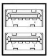
Table A.3: Connector Pin Assignments
| Pin Signal Name Description | |
| 1 VBUS Power | |
| 2 D- USB 2.0 differential pair | |
| 3 | D+ |
| 4 GND Ground for power return | |
A.3.2 USB 3.0 Connector

Table A.4: USB 3.0 Connector Pin Assignments
| Pin Signal Name Description | ||
| 1 VBUS Power | ||
| 2 | D- | USB 2.0 differential pair |
| 3 | D+ | |
| 4 GND Ground for power return | ||
| 5 StdA_SSRX- | SuperSpeed receiver differential pair | |
| 6 StdA_SSRX+ | ||
| 7 GND_DRIAN Ground for signal return | ||
| 8 StdA_SSTX- | SuperSpeed transmitter differential pair | |
| 9 StdA_SSTX+ | ||
A.4 Display Connector (CN2, CN3)
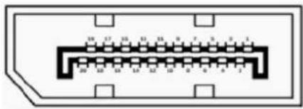
Table A.5: DisplayPort Adapter Cable Pin Assignments
| Pin Signal Name |
| 1 ML_Lane 0 (p) |
| 2 GND |
| 3 ML_Lane 0 (n) |
| 4 ML_Lane 1 (p) |
| 5 GND |
| 6 ML_Lane 1 (n) |
| 7 ML_Lane 2 (p) |
| 8 GND |
| 9 ML_Lane2 (2) |
| 10 ML_Lane 3 (p) |
| 11 GND |
| 12 ML_Lane 3 (n) |
| 13 CONFIG1 |
| 14 CONFIG2 |
| 15 AUX CH (p) |
| 16 GND |
| 17 AUX CH (n) |
| 18 Hot Plug |
| 19 Return |
A.5 M.2 Connector (CN15)

Table A.6: M.2 B-Key Connector Pin Assignments
| Pin Signal Name Pin Signal Name | |
| 1 M2_SATA1_DET 2 +V3.3_M2 | |
| 3 GND 4 +V3.3_M2 | |
| 5 GND 6 M2_LTE_PWR_OFF# | |
| 7 M2_LTE_USB_DP 8 M2_LTE_W1_DISABLE_N | |
| 9 M2_LTE_USB_DN 10 +V3.3_M2 | |
| 11 GND 12 Mechanical notch B | |
| 13 Mechanical notch B 14 Mechanical notch B | |
| 15 Mechanical notch B 16 Mechanical notch B | |
| 17 Mechanical notch B 18 Mechanical notch B | |
| 19 Mechanical notch B 20 NC | |
| 21 NC | 22 NC |
| 23 WAKE_ON_WAN# | 24 NC |
| 25 NC | 26 M2_LTE_W2_DISABLE_N |
| 27 GND 28 NC | |
| 29 USB_Z_SSRX1- | 30 M2_SIM1_RESET |
| 31 USB_Z_SSRX1+ | 32 M2_SIM1_CLK |
| 33 GND 34 M2_SIM1_DATA | |
| 35 USB_C_SSTX1- | 36 M2_SIM1_PWR |
| 37 USB_C_SSTX1+ | 38 NC |
| 39 GND 40 M2_SIM2_DET | |
| 41 SATA1_RX+ | 42 NC |
| 43 SATA1_RX- | 44 NC |
| 45 GND 46 NC | |
| 47 SATA1_C_TX- | 48 NC |
| 49 SATA1_C_TX+ | 50 NC |
| 51 GND 52 NC | |
| 53 NC | 54 NC |
| 55 NC | 56 NC |
| 57 GND 58 NC | |
| 59 NC | 60 NC |
| 61 NC | 62 NC |
| 63 NC | 64 NC |
| 65 NC | 66 M2_SIM1_DET |
| 67 LTE_RST#_P67 | 68 NC |
| 69 NC | 70 +V3.3_M2 |
| 71 GND 72 +V3.3_M2 | |
| 73 GND 74 +V3.3_M2 | |
| 75 NC | |
A.6 mPCIe Connector (MINI1)

Table A.7: mPCIe Connector Pin Assignments
Pin Signal Name Pin Signal Name
| 1 PCIE_WAKE#_3.3 2 +V3.3_MINI | ||
| 3 NC 4 GND | ||
| 5 NC 6 +V1.5 | ||
| 7 +V3.3 8 NC | ||
| 9 GND 10 NC | ||
| 11 CLK_PCIE_mPCIe1- 12 NC | ||
| 13 | CLK_PCIE_mPCIe1+ | 14 NC |
| 15 | GND 16 NC | |
| 17 | NC 18 GND | |
| 19 | NC 20 WIFI_DISABLE# | |
| 21 | NC 22 MINI_PLTRST# | |
| 23 | PCIE_mPCIe_RX4- | 24 +V3.3_MINI |
| 25 | PCIE_mPCIe_RX4+ | 26 GND |
| 27 | GND 28 +V1.5 | |
| 29 | GND 30 NC | |
| 31 | PCIE_TX2-_Z | 32 NC |
| 33 | PCIE_TX2+Z | 34 GND |
| 35 | GND 36 USB_Z_P0- | |
| 37 | GND 38 USB_Z_P0+ | |
| 39 | +V3.3_MINI | 40 GND |
| 41 | +V3.3_MINI | 42 NC |
| 43 | MPCIE_PWRSEL 44 NC | |
| 45 | NC 46 NC | |
| 47 | NC 48 +V1.5 | |
| 49 | NC 50 GND | |
| 51 | NC 52 +V3.3_MINI | |
A.7 COM Port RS232/422/485 Settings
The default setting for the COM port is RS-232. This can be changed to RS-422 or RS-485 modes and can be configured by adjusting the switch on the motherboard.
A.7.1 COM1/COM2 TS232/422/485 Settings (SW1)
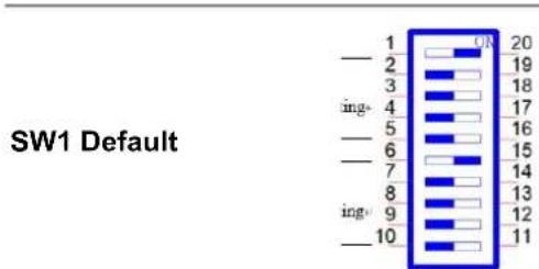
Description settings This switch is used to select RS232/422/485 mode setting
Default RS232 mode
A.7.2 COM3/COM4 RS232/422/485 Settings (SW2)
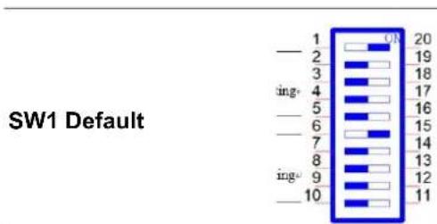
Description settings This switch is used to select RS232/422/485 mode setting
Default RS232 mode
| RS232 Mode | Bit 1 ON |  | |
| Bit 2,3,4,5,6,7,8,9,10 OFF | |||
| COM1 | RS485 Mode | Bit 2,4,5 ON |  |
| Bit 1,3,6,7,8,9,10 OFF | |||
| RS422 Mode | Bit 1,2,4,5 ON |  | |
| Bit 3,6,7,8,9,10 OFF |
| COM2 | RS232 Mode | Bit 6 ON | 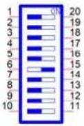 |
| Bit 1,2,3,4,5,7,8,9,10 OFF | |||
| RS485 Mode | Bit 7,9,10 ON |  | |
| Bit 1,2,3,4,5,7,8 OFF | |||
| RS422 Mode | Bit 6,7,9,10 ON |  | |
| Bit 1,2,3,4,5,8 OFF | |||
| COM3 | RS232 Mode | Bit 1 ON |  |
| Bit 2,3,4,5,6,7,8,9,10 OFF | |||
| RS485 Mode | Bit 2,4,5 ON | 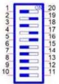 | |
| Bit 1,3,6,7,8,9,10 OFF | |||
| RS422 Mode | Bit 1,2,4,5 ON | 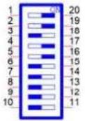 | |
| Bit 3,6,7,8,9,10 OFF | |||
| COM4 | RS232 Mode | Bit 6 ON |  |
| Bit 1,2,3,4,5,7,8,9,10 OFF | |||
| RS485 Mode | Bit 7,9,10 ON |  | |
| Bit 1,2,3,4,5,7,8 OFF | |||
| RS422 Mode | Bit 6,7,9,10 ON | 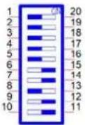 | |
| Bit 1,2,3,4,5,8 OFF |
A.7.3 COM Port RS422/485 Termination Resistor Settings
| SW1 Termination Resistor Setting | |||
| Description | This switch is used to select the Termination Resistor (120 ohm) for long distance transmission or device matching. | ||
| Default Bit3 off & Bit8 off | |||
| COM1 Bit3 on |  | ||
| COM2 Bit8 on | |||
| SW2 Termination Resistor Setting | ||
| Description | This switch is used to select the Termination Resistor (120 ohm) for long distance transmission or device matching. | |
| Default Bit3 off & Bit8 off | ||
| COM3 Bit3 on |  | |
| COM4 Bit8 on | ||
A.8 BIOS Update Settings
Use SW4 to set BIOS1/2 update selection, BIOS1 (Default), BIOS2 (PCIe x4) for Factory Engineering staff use.

BIOS1: Configure to Setting 1 (Default)

BIOS2: Configure to Setting 3
A.9 AT/ATX Setting (SW8)
SW8 can be used for the AT/ATX setting. The default setting is AT mode. See the following table for switch configuration.
| SW8 Default |  | |
| Description | Instruction SW8 | |
| AT Mode (Default) Bit 1 off |  | |
| ATX Mode Bit 1 on |  | |
A.10 Riser Connector (CN12)
Table A.8: Expansion Board to Board Connector Pin Assignments
| Pin Signal Name Pin Signal Name | ||
| A1 DCIN B1 GND | ||
| A2 DCIN B2 GND | ||
| A3 DCIN B3 GND | ||
| A4 DCIN B4 GND | ||
| A5 N/A B5 SMB_CLK | ||
| A6 GND B6 SMB_DAT | ||
| A7 GND B7 GND | ||
| A8 GND B8 +V5 | ||
| A9 USB+ B9 +V5 | ||
| A10 USB- | B10 | +V5 |
| A11 GND B11 +V5 | ||
| A12 GND B12 | PCIeX4_EN | |
| A13 CLK+ | B13 | GND |
| A14 CLK- | B14 | RX0+ |
| A15 GND B15 | RX0- | |
| A16 TX0+ | B16 | GND |
| A17 TX0- | B17 | SLP_S3 |
| A18 GND B18 | GND | |
| A19 N/A B19 | RX1+ | |
| A20 GND B20 | RX1- | |
| A21 TX1+ | B21 | GND |
| A22 TX1- | B22 | GND |
| A23 GND B23 | RX2+ | |
| A24 GND B24 | RX2- | |
| A25 TX2+ | B25 | GND |
| A26 TX2- | B26 | GND |
| A27 GND B27 | RX3+ | |
| A28 GND B28 | RX3- | |
| A29 TX3+ | B29 | GND |
| A30 TX3- | B30 | PLTRST |
| A31 GND B31 | SATA0_DET | |
| A32 SATA1_DET | B32 | GND |
A.11 TPM 2.0 BIOS Settings
UNO-148 systems support TPM 2.0 functionality. This can be enabled or disabled in the BIOS menu by following the instructions provided below:
-
Power on the UNO-148 system and press "Delete" to enter the BIOS configuration menu.
-
On the "Advanced" tab, select "Trusted Computing".

- Then select "Security Device Support".
- Choose "Enable/Disable" to enable or disable the TPM 2.0 function (The default setting is to disable this function).
| TPM 2.0 Device Found Firmware Version: 7.63 Vendor: IFX | Enables or Disables BIOS support for security device. 0.S. will not show Security Device. TCG EFI protocol and INT1A interface will not be available. | |
| Security Device Support [Enable] Active PCR banks SHA256 Available PCR banks SHA-1,SHA256 | ||
| SHA-1 PCR Bank [Disabled] SHA256 PCR Bank [Enabled] | ||
| Pending operation [None] Platform Hierarchy [Enabled] Storage Hierarchy [Enabled] Endorsement Hierarchy [Enabled] TPM 2.0 UEFI Spec Version [TCG_2] Physical Presence Spec Version [1.3] TPM 2.0 InterfaceType [TIS] Device Select [Auto] | +: Select Screen ↑↓: Select Item Enter: Select +/-: Change Opt. F1: General Help F2: Previous Values F3: Optimized Defaults F4: Save & Exit ESC: Exit | |
A.12 CPU Turbo Mode BIOS Settings
The UNO-148 system supports CPU Turbo mode. This can be enabled or disabled in the BIOS menu through the following instructions:
-
Power on the UNO-148 system and press "Delete" to enter the BIOS configuration menu.
-
On the "Advanced" tab, select "Power & Performance".
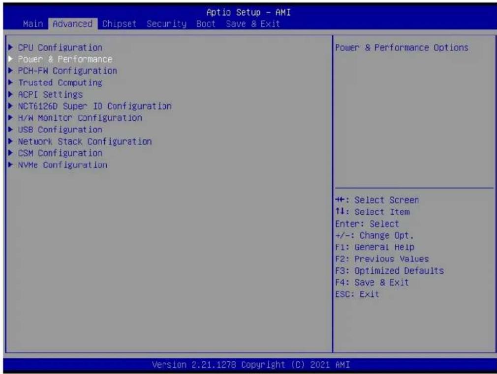
- Then select "CPU Power Management Control".

- Choose "Enable/Disable" to enable or disable CPU Turbo mode (The default setting is to disable this function).
![Advanced CPU - Power Management Control Boot performance mode [Max Non-Turbo Performance] Intel(R) SpeedStep(tm) [Enabled] Intel(R) Speed Shift Technology [Enabled] HDC Control [Enabled] Turbo Mode [Disabled] View/Configure Turbo Options Config TDP Configurations Platform FL1 Enable [Disabled] Platform FL2 Enable [Disabled] Power Limit 4 Override [Disabled] C states [Disabled] Power Limit 3 Settings CPU Lock Configuration Enable/Disable processor Turbo Mode (requires EMTTM enabled too). AUTO means enabled. ++: Select Screen ↑↓: Select Item Enter: Select +/-: Change Opt. F1: General Help F2: Previous Values F3: Optimized Defaults F4: Save & Exit ESC: Exit Version 2.21.1278 Copyright (C) 2021 AMI](/content/2026/05/958249/images/dc4a80e913273a9ee7012827f074f65fbeb71e2fbacdcb5d87dd3ab703a556ae.jpg)
A.13 TDP Power Consumption BIOS Settings
The UNO-148 system supports Power Management Control for TDP switching. This can be enabled or disabled in the BIOS menu by following these instructions:
- Power on the UNO-148 system and press "Delete" to enter the BIOS configuration mode.
- On the "Advanced" tab, select the "Power & Performance" item.
| Aptio Setup - AMI Main Advanced Chipset Security Boot Save & Exit | |
| CPU Configuration Power & Performance PCH-FW Configuration Trusted Computing ACPI Settings NCT6126D Super IO Configuration H/W Monitor Configuration USB Configuration Network Stack Configuration CSM Configuration NVMe Configuration | Power & Performance Options |
| +: Select Screen ↑↓: Select Item Enter: Select +/-: Change Opt. F1: General Help F2: Previous Values F3: Optimized Defaults F4: Save & Exit ESC: Exit | |
- Then select the "CPU Power Management Control" item.

- Then select the "Config TDP Configurations" item.
![Advanced Aptio Setup - AMI CPU - Power Management Control Boot performance mode [Max Non-Turbo Performance] Intel(R) SpeedStep(tm) [Enabled] Intel(R) Speed Shift Technology [Enabled] HDC Control [Enabled] Turbo Mode [Disabled] View/Configure Turbo Options Config TDP Configurations Platform FL1 Enable [Disabled] Platform FL2 Enable [Disabled] Power Limit 4 Override [Disabled] C states [Disabled] Power Limit 3 Settings CPU Lock Configuration Config TDP Configurations +: Select Screen ↑↓: Select Item Enter: Select +/-: Change Opt. F1: General Help F2: Previous Values F3: Optimized Defaults F4: Save & Exit ESC: Exit Version 2.21.1278 Copyright (C) 2021 AMI](/content/2026/05/958249/images/bed0900a37c5f55b93637fc7b767141063f00c0b46853ebcabacae29238e8560.jpg)
- From the "TDP Boot Mode" options, choose "UP" for standard spec usage. ("Nominal" 28 W, "UP" 15 W, "Down" 12 W)
![Optio Setup - AMI Advanced Config TDP Configurations Enable Configurable TDP [Applies to cTDP] Configurable TDP Boot Mode [Up] Configurable TDP Lock [Disabled] ConfigTDP Levels 3 ConfigTDP Turbo Activation Ratio 17 (Unlocked) Power Limit 1 15.0W (MSR:15.0) Power Limit 2 60.0W (MSR:60.0) Custom Settings Nominal ConfigTDP Nominal Power Limit 1 Power Limit 2 Power Limit 1 Time Window ConfigTDP Turbo Activation Ratio 0 Custom Settings Down ConfigTDP Level1 Ratio:12 TAR:11 PL1:12.0W Power Limit 1 0 Power Limit 2 0 Power Limit 1 Time Window [0] ConfigTDP Turbo Activation Ratio 0 Configurable TDP Boot Mode Nominal Down Up Deactivate Select Screen Select Item er: Select +/-: Change Opt. F1: General Help F2: Previous Values F3: Optimized Defaults F4: Save & Exit ESC: Exit Version 2.21.1278 Copyright (C) 2021 AMI](/content/2026/05/958249/images/cfcac1f40bc106ade4615886877e04f0b4e7215d7292302fdd65967e6a4c20ab.jpg)
Note! System will perform a short reboot every time (Power LED will turn orange for a short while) with the default TDP setting due to a CPU feature. It doesn't affect system stability in the long term.
A.14 Storage RAID Configuration (VMD Setup)
UNO-148 has special RAID configuration steps which differ from previous CPU generations. Customers can enable RAID with 2 x SATA storage or 2 x NVMe storage. SATA RAID: M.2 B-Key & 2.5" HDD/SSD (UNO-148 base unit + UNO-148-IS2EA) PCIe RAID: M.2 M-Key & PCIe x4 slot (UNO-148 base unit + UNO-148-P11EA, needs PCIe x4 to M.2 M NVMe transfer card)
Please refer to the below configuration instructions:
- Go to Chipset→VMD setup menu.

- Set VMD controller to "Enabled".
![Chipset Aptio Setup - AMI VMD Configuration Enable VMD controller [Disabled] Enable VMD controller Disabled Enabled Enable/Disable to VMD controller +: Select Screen ↓: Select Item Enter: Select +/-: Change Opt. F1: General Help F2: Previous Values F3: Optimized Defaults F4: Save & Exit ESC: Exit Version 2.21.1278 Copyright (C) 2021 AMI](/content/2026/05/958249/images/562228d3508cddc61ec20db20ab08afda80550d3836cf7835cf5bdd707410bcf.jpg)
- The system will detect the storage type (SATA/NVMe) and the RAID option will automatically pop up and the corresponding storage device will be installed.
SATA RAID
![Chipset Aptio Setup - AMI VMD Configuration Enable VMD controller [Enabled] SATA RAID [Disabled] RAID0 [Enabled] RAID1 [Enabled] SATA RAID Disabled Enabled SATA RAID +: Select Screen ↑↓: Select Item Enter: Select +/-: Change Opt. F1: General Help F2: Previous Values F3: Optimized Defaults F4: Save & Exit ESC: Exit Version 2.21.1278 Copyright (C) 2021 AMI](/content/2026/05/958249/images/9cc1c865f645915cde22602614a245b12fc7d80149e4b319b5b74a1b9a5ecbdd.jpg)
PCIe RAID (NVMe)
![Chipset Aptio Setup - AMI VMD Configuration Enable VMD controller [Enabled] PCIe RAID(NVMe) [Disabled] PCIe RAID(NVMe) [Disabled] RAID0 [Enabled] RAID1 [Enabled] PCIe RAID(NVMe) Disabled Enabled PCIe RAID(NVMe) ++: Select Screen ↑↓: Select Item Enter: Select +/-: Change Opt. F1: General Help F2: Previous Values F3: Optimized Defaults F4: Save & Exit ESC: Exit Version 2.21.1278 Copyright (C) 2021 AMI](/content/2026/05/958249/images/89b27ba4430f97892ed0bba3802bfe6dc82f21d19f18ceb28d56c5498815d17e.jpg)
A.15 Dynamic Range Temperature Statement
Thermal Management of the 11th Gen Intel® Core™ Processor External Design Specification:
DTR is the range of temperature starting from boot (TBOOT) and transitioning to Cold-to-Hot (TBOOT + DTR) and/or Hot-to-Cold (TBOOT - DTR). A temperature outside the DTR range requires a reboot but is not enforced by the hardware. (A manual reboot can recover the system).
www.advantech.com
Please verify specifications before quoting. This guide is intended for reference purposes only.
All product specifications are subject to change without notice.
No part of this publication may be reproduced in any form or by any means, such as electronically, by photocopying, recording, or otherwise, without prior written permission from the publisher.
All brand and product names are trademarks or registered trademarks of their respective companies.
© Advantech Co., Ltd. 2022


- UNO-148 Industrial PC
- Copyright
- Acknowledgments
- Support
- Product Warranty (2 years)
- Declaration of Conformity
- CE
- FCC Class A
- 甲類資訊技術設備
- Technical Support and Assistance
- Safety Precautions - Static Electricity
- Safety Instructions
- Chapter 2 Hardware Functionality......9
- Chapter 3 Initial Setup.... 25
- Appendix A System Settings / Pin Assignments 53
- Chapter 1
- Overview
- Introduction
- Safety Precautions
- Warning!
- Caution!
- Hardware Specifications
- General
- System Hardware
- I/O Interfaces
- Environment
- Certification
- Extension Kit (Optional)
- Dimensions
- Chapter 2
- Hardware
- Functionality
- Introduction
- External I/O Connector
- UNO-148 Base Unit
- UNO-148 Base Unit with UNO-148-IS2EA Expansion Unit (1 x iDoor and 1 x 2.5" SSD/HDD)
- UNO-148 Base Unit with UNO-148-ID1EA Expansion Unit (iDoor x 1)
- UNO-148 Base Unit with UNO-148-P11EA Expansion Unit (1 x PCIe x4 expansion)
- Power Connector
- LAN: Ethernet Connectors
- USB Connectors
- Display Connectors
- COM Connector
- Digital Inputs and Outputs
- Digital Input
- Digital Output
- Isolated Digital Input
- Isolated Digital Output
- Internal I/O Connectors and Switches
- M.2 Connector
- mPCIe Connector
- Nano SIM Slot
- Others
- LED Indicators
- Reset Buttons
- Antenna Hole
- Chapter 3
- Initial Setup
- Chassis Grounding
- Connecting Power
- Storage Installation (Optional)
- Installing M.2 2280 NVMe
- Installing the M.2 3042 Module
- Installing the M.2 3052 Module
- Installing the M.2 2230 Module
- Installing mPCIe
- DIN-Rail Installation
- Wireless Module Installation (Optional)
- Extension Kit Installation (Optional)
- iDoor and HDD/SSD Storage Extension Kit (UNO-148-IS2EA)
- iDoor Extension Kit (UNO-148-ID1EA)
- PCIe x4 Expansion (UNO-148-P11EA)
- Remote Power & Reset Settings
- BIOS Setting
- Appendix A
- A.1 Power Connector (CN1)
- A.2 LAN: Ethernet Connector (CN4)
- A.3 USB Connectors (CN5, CN6)
- A.3.1 USB 2.0 Connector
- A.3.2 USB 3.0 Connector
- A.4 Display Connector (CN2, CN3)
- A.5 M.2 Connector (CN15)
- A.6 mPCIe Connector (MINI1)
- A.7 COM Port RS232/422/485 Settings
- A.7.1 COM1/COM2 TS232/422/485 Settings (SW1)
- A.7.2 COM3/COM4 RS232/422/485 Settings (SW2)
- A.7.3 COM Port RS422/485 Termination Resistor Settings
- A.8 BIOS Update Settings
- A.9 AT/ATX Setting (SW8)
- A.10 Riser Connector (CN12)
- A.11 TPM 2.0 BIOS Settings
- A.12 CPU Turbo Mode BIOS Settings
- A.13 TDP Power Consumption BIOS Settings
- A.14 Storage RAID Configuration (VMD Setup)
- PCIe RAID (NVMe)
- A.15 Dynamic Range Temperature Statement
- www.advantech.com
Brand : Advantech
Model : UNO-148-B33BA
Category : Industrial computer