
Core III - Monitor Christie - Free user manual and instructions
Find the device manual for free Core III Christie in PDF.


| Product Type | Monitor |
| Brand | Christie |
| Model | Core III |
| Display Technology | LCD |
| Screen Size | 27 inches |
| Resolution | 1920 x 1080 pixels (Full HD) |
| Refresh Rate | 60 Hz |
| Contrast Ratio | 1000:1 |
| Brightness | 250 cd/m² |
| Viewing Angle | 178° horizontal / 178° vertical |
| Connectivity | 1x HDMI, 1x DVI, 1x VGA, 1x DisplayPort |
| Power Supply | 100-240V AC, 50/60Hz |
| Power Consumption (Typical) | 65 W |
| Weight (with stand) | 8.5 kg |
| Dimensions (W x H x D) without stand | 620 x 370 x 50 mm |
| VESA Mount Compatibility | 100 x 100 mm |
| Adjustable Stand | Tilt, swivel, height adjustment |
| Built-in Speakers | Yes, 2 x 5W |
| Operating Temperature | 5°C to 35°C |
| Warranty | 3 years |
Frequently Asked Questions - Core III Christie
User questions about Core III Christie
0 question about this device. Answer the ones you know or ask your own.
Ask a new question about this device
Download the instructions for your Monitor in PDF format for free! Find your manual Core III - Christie and take your electronic device back in hand. On this page are published all the documents necessary for the use of your device. Core III by Christie.
USER MANUAL Core III Christie
Installation and Setup Guide
020-002147-02
LED Display System
Christie Core III Series
CHRISTIE®
NOTICES
COPYRIGHT AND TRADEMARKS
Copyright © 2024 Christie Digital Systems USA, Inc. All rights reserved.
All brand names and product names are trademarks, registered trademarks or trade names of their respective holders.
GENERAL
Every effort has been made to ensure accuracy, however in some cases changes in the products or availability could occur which may not be reflected in this document. Christie reserves the right to make changes to specifications at any time without notice. Performance specifications are typical, but may vary depending on conditions beyond Christie's control such as maintenance of the product in proper working conditions. Performance specifications are based on information available at the time of printing. Christie makes no warranty of any kind with regard to this material, including, but not limited to, implied warranties of fitness for a particular purpose. Christie will not be liable for errors contained herein or for incidental or consequential damages in connection with the performance or use of this material. Our centers of excellence for manufacturing in Kitchener, Ontario, Canada and in Shenzhen, China are ISO 9001:2015 Quality Management System-certified.
Christie is committed to making our documents free from language bias; however, we are not responsible for the language used on any linked or third-party documentation.
For the most current technical documentation and office contact information, visit HYPERLINK "https://www.christiedigital.com/" www.christiedigital.com.
WARRANTY
Products are warranted under Christie's standard limited warranty, the details of which are available at https://www.christiedigital.com/help-center/warranties/ or by contacting your Christie dealer or Christie.
PREVENTATIVE MAINTENANCE
Preventative maintenance is an important part of the continued and proper operation of your product. Failure to perform maintenance as required, and in accordance with the maintenance schedule specified by Christie, voids the warranty for preventative maintenance schedules, refer to HYPERLINK "https://www.christiedigital.com/" www.christiedigital.com.
REGULATORY (if applicable)
The product has been tested and found to comply with the limits for a Class A digital device, pursuant to Part 15 of the FCC Rules. These limits are designed to provide reasonable protection against harmful interference when the product is operated in a commercial environment. The product generates, uses, and can radiate radio frequency energy and, if not installed and used in accordance with the instruction manual, may cause harmful interference to radio communications. Operation of the product in a residential area is likely to cause harmful interference in which case the user will be required to correct the interference at the user's own expense.
CAN ICES-3 (A) / NMB-3 (A)
The product is designed and manufactured with high-quality materials and components that can be recycled and reused. This symbol means that electrical and electronic equipment, at their end-of-life, should be disposed of separately from regular waste. Please dispose of the product appropriately and according to local regulations. In the European Union, there are separate collection systems for used electrical and electronic products.
If printing this document, consider printing only the pages you need and select the double-sided option.
Please help us to conserve the environment we live in!
NOTATION
Learn the hazard and information symbols used in the product documentation.

Danger! If not avoided, the following could result in death or serious injury.
Warning! If not avoided, the following could result in death or serious injury.
Caution! If not avoided, the following could result in minor or moderate injury.
Notice. If not avoided, the following could result in property damage.
Content
Product overview 4
Important safeguards....4
General safety precautions....4
Power precautions 5
Terminology 5
Product documentation....6
Related documentation....6
Required tools 6
Typical LED solution 7
Cable and controller layout and design....8
Installation and setup....9
Installing the Vertical Mounting Poles....10
Mounting the tiles 15
Connecting the data source cables 17
Connecting the power cables....17
Installing the LED modules....18
Powering on the array 20
Powering off the array 20
Connecting to video sources....20
Regulatory 21
Safety 21
Electro-magnetic compatibility 21
Emissions 21
Immunity 21
Product overview
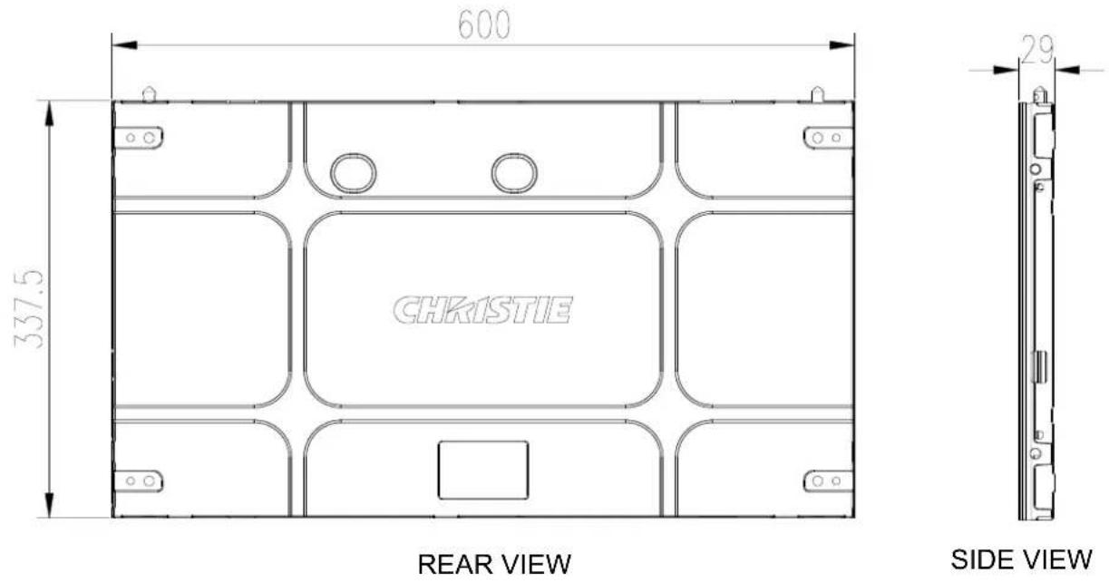
Christie Core III has been fully upgraded on the previous basis. Featuring UHD resolution, high fill-factor, and advanced monitoring capabilities, the Core III is a certified LED display wall solution providing 24/7 operation for critical viewing environments. With front-access serviceability, remote, and a slim ADA-compliant design, Core III delivers performance possible for LED displays.

natural_image
Pure electrical circuit lines without any symbolsTOP VIEW
Important safeguards
To prevent personal injury and to protect the device from damage, read and follow these safety precautions.
General safety precautions
To prevent personal injury and to protect the device from damage, read and follow these safety precautions.

Warning! If not avoided, the following could result in death or serious injury.
- Observe all electrostatic precautions. Use a grounded wrist strap and insulated tools when handling, servicing, or cleaning electronic assemblies.
- A certified electrician must be present during installation to ensure the installation meets the local electrical code.
- Motors and fans may start without warning.

Notice. If not avoided, the following could result in property damage.
- Always wear clean, lint-free gloves when handling the product.
Power precautions
Ensure all power precautions are understood before installing the product.

Warning! If not avoided, the following could result in death or serious injury.
- After the replacement of the power supply, hi-pot and ground/earth bond tests must be performed. Only Christie qualified technicians who are familiar with the necessary precautions can perform these tests.
- A certified electrician must be present during installation to ensure the installation meets the local electrical code.
- Always connect the ground or earth first to reduce shock hazard.
- Do not return the current through the ground or earth.
- SHOCK HAZARD! The line cord has a maximum power carrying capability. For the maximum number of tiles that may be connected per daisy chain when connecting to the power supply, refer to the product specifications.
- SHOCK HAZARD! A permanent single-phase connection must be installed between the LED tile system and the AC power supply.
- FIRE AND SHOCK HAZARD! Do not operate the system unless certified power connections, providing the recommended voltage, are used.
- HIGH TOUCH CURRENT HAZARD! To ensure reliable grounding, the power connection must be made by using an industrial plug (pluggable type B) or be provided by a permanent connection.
- A 13-20 A double pole mains circuit breaker, certified for the applicable local regulations, is required. It must be part of the building installation and easily accessible.
- Do not use a wall breaker greater than 20 A. This could result in severe damage to the tile system in the event of a failure.

Caution! If not avoided, the following could result in minor or moderate injury.
- SHOCK HAZARD! The line cord has a maximum power carrying capability. For the maximum number of tiles that may be connected per daisy chain when connecting to the power supply, refer to the product specifications.
- SHOCK HAZARD! Only use the AC power cord provided with the product or recommended by Christie.
- TRIP OR FIRE HAZARD! Position all cables where they cannot contact hot surfaces, be pulled, be tripped over, or damaged by persons walking on or objects rolling over the cables.
- FIRE HAZARD! Do not use a power cord, harness, or cable that appears damaged.
- FIRE OR SHOCK HAZARD! Do not overload power outlets and extension cords.
- Only Christie qualified technicians are permitted to open product enclosures.
Terminology
Learn about the components of the LED display system.
| Term | Definition |
| Tile | A cabinet that contains several LED modules. |
| Array | A group of connected tiles that from a larger display. |
| Controller | Controls the LED display system array and video input source. Sometimes referred to as the control unit. |
| Pixel | A group of one red, one green, and one blue dot. |
| Subpixel | A pixel is comprised of three subpixels, one for each color: red, green, and blue. Each subpixel in LED display technology is and LED chip. |
| Pixel pitch | Specified the distance from the center of one pixel to the center of the next pixel. |
| SMD package size | A technical supplier specification related to the pixel size and denotes the size of the surface-mounted diode (SMD). |
| Fill factor | Indicates the ratio between the area covered by pixels and the area not covered by pixels. |
Product documentation
For installation, setup, and user information, see the product documentation available on the Christie Digital Systems USA Inc. website. Read all instructions before using or servicing this product.
-
Access the documentation from the Christie website:
-
Go to this URL: http://bit.ly/2qXBAdX or https://www.christiedigital.com/en-us/digital-signage/products/led-tiles/coreplus-series.
- Scan the QR code using a QR code reader app on a smartphone or tablet.
- On the product page, select the model and switch to the Download tab.
Related documentation
Additional information on the Core LED Display System is available in the following documents.
• LED Control Unit User Guide (P/N: 020-102717-XX)
• LED Control Unit User Guide (P/N: 020-102222-XX)
Required tools
Make sure the following tools are available during the installation.
- Rubber hammer
- Utility knife
- Allen key
-
Spirit level
-
Tape measure
- Anti-static glove
- socket wrench
- Torque driver
- Torque wrench
• Philips screwdriver, with magnetic tip - Slotted screwdriver, with magnetic tip
• LED module removal tool for Core III (P/N: 003-007099-XX) - Attachment Block Template for Core III (P/N: 003-007100-XX)
Typical LED solution
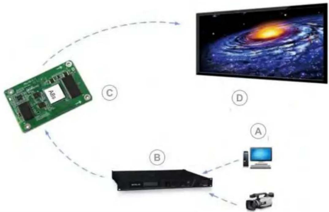
The controller transmits commands and displays contents from a PC or video signal from the other media player to an LED screen.
flowchart
graph TD
    A["Green Circuit Board"] -->|C| B["Satellite"]
    B -->|D| C["Computer"]
    B -->|B| D["Video Device"]
    style A fill:#99ccff,stroke:#333
    style B fill:#99ccff,stroke:#333
    style C fill:#99ccff,stroke:#333
    style D fill:#99ccff,stroke:#333
| A | Media sources |
| B | LED control unit |
| C | Receiving card A8s-N |
| D | LED display |
Cable and controller layout and design
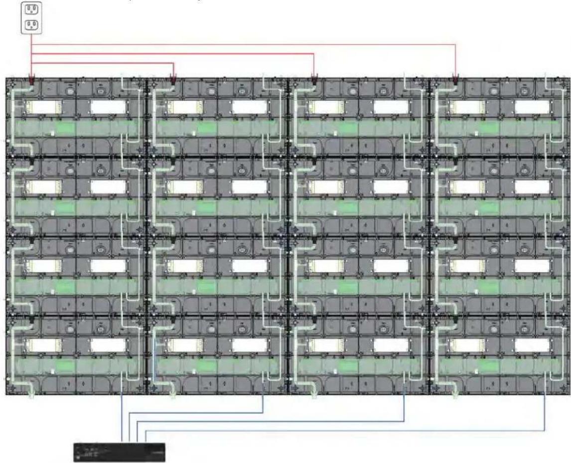
Before an array is constructed, you must plan the design layout of the tiles to make sure the controller placement and the cabling layout support the overall tile design objectives.
The LED display system offers flexibility in terms of the number of media sources displayed and the overall resolution. Color and brightness matching, as well as other functions, can be performed across an entire array.
The video source connections between the cabinets are represented by the blue line. The power connections between the cabinets are represented by the red line.
Installation and setup
The configuration of an array depends on the installation. Use the following instructions as a guideline only. Before you install an LED array, fully understand all site requirements and characteristics.
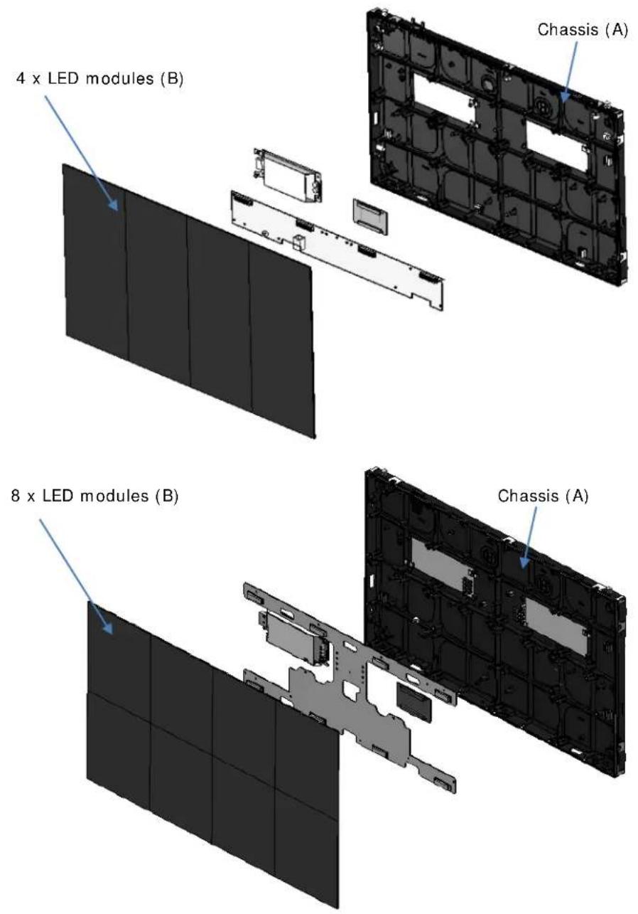
Installing an LED array from the front
Perform the following steps when you install an LED array while facing the LED modules.
-
Install the vertical mounting poles (on page 10).
-
Mount the tiles (A) (on page 15).
-
Connect the data cables (on page 17).
-
Connect the power cables between tiles (on page 17).
-
Install the LED modules (B) (on page 18).
-
Power on the array (on page 20).
-
Configure and connect the LED Controller according to the instructions in the LED Control Unit User Guide.
The controller can be configured at any time. Before connecting the controller to the wall, Christie recommends updating the firmware and configuring the controller.
-
Install the Christie controller software.
-
Configure the LED control unit.
Installing the Vertical Mounting Poles
If the tiles are being installed onto a flat wall surface, determine where vertical mounting poles should be installed, and attach them to the support structure.

Warning! If not avoided, the following could result in death or serious injury.
- External support for a display wall must be designed and implemented by a Christie qualified installer and must comply with local area regulations and safety standards.
- All display walls must have permanent external supports. The amount of external support required depends on the size of the display wall.
- A minimum of two people or appropriately rated lift equipment is required to safely lift, install, or move the product.
The vertical mounting poles are available in five different configurations:
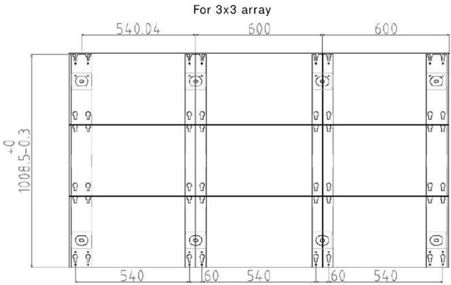
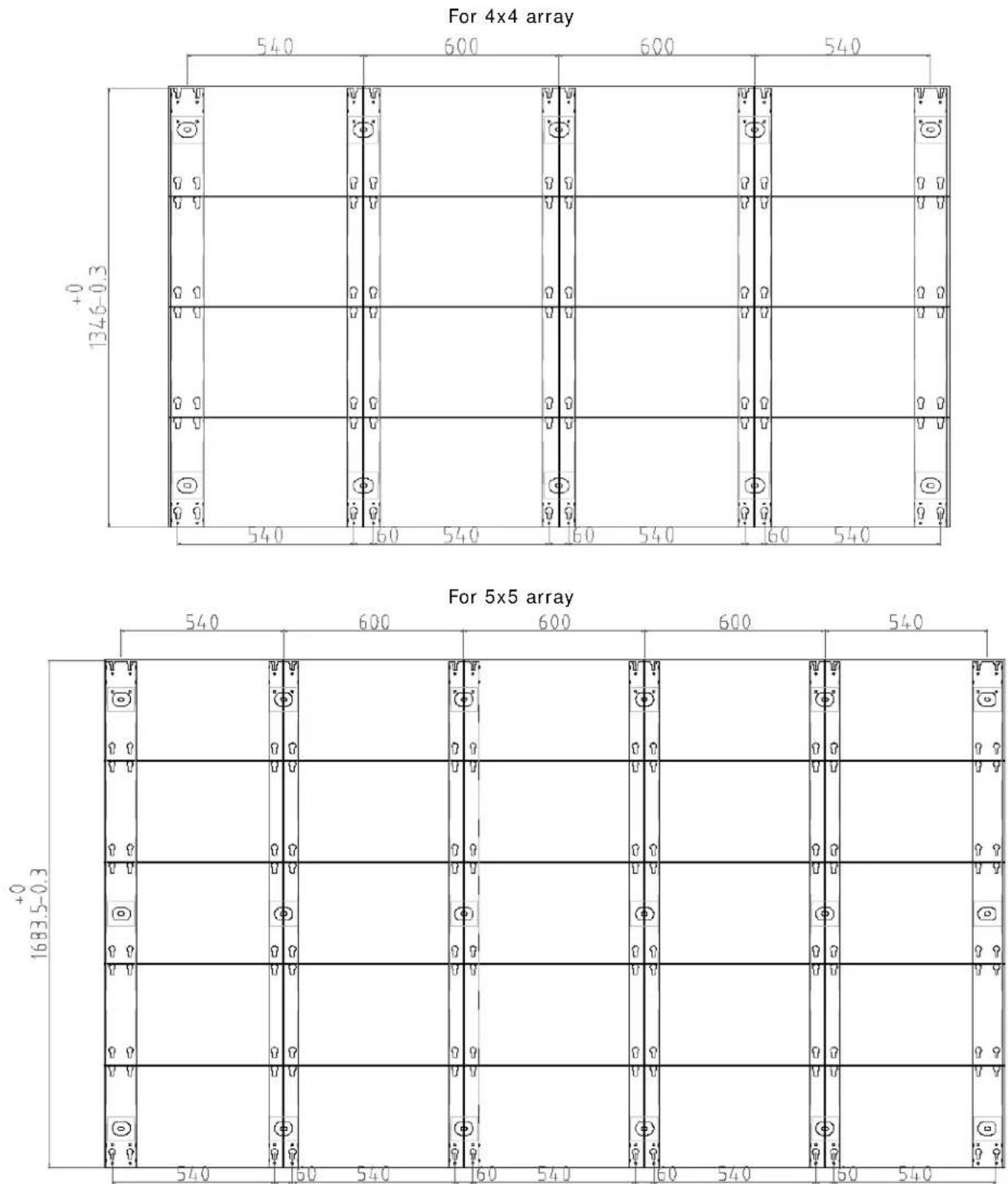
For 6x6 array
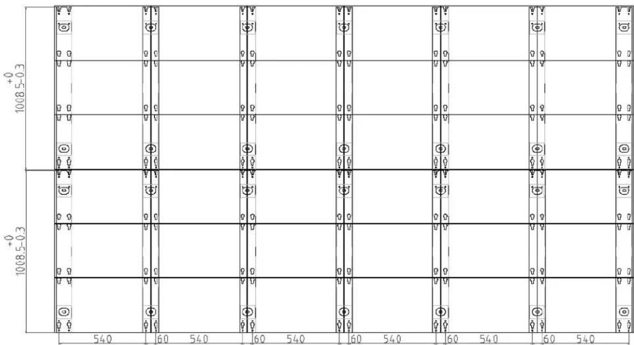
bar
| Level | Column 1 | Column 2 | Column 3 | Column 4 | Column 5 | Column 6 | Column 7 | Column 8 | |-------|----------|----------|----------|----------|----------|----------|----------|----------| | +0 | | | | | | | | | | 1008.5-0.3 | | | | | | | | | | +0 | | | | | | | | | | 1008.5-0.3 | | | | | | | | | | | | | | | | | | | | | | | | | | | | | | | | | | | | | | | | | | | | | | | | | | | | | | | | | | | | | | - | | | | | | | | | | - | | | | | | | | | | - | | | | | | | | | | - | | | | | | | | | | - | | | | | | | | | | - | | | | | | | | | | - | | | | | | | | | | - | | | | | | | | / 540 / 60 / 540 / 60 / 540 / 60 / 540 / 60 / 540 / 60 / 540 / 60 / 540 / 60 / 540 / 60 / 540 / 60 / 540 / 60 )For 8x8 array
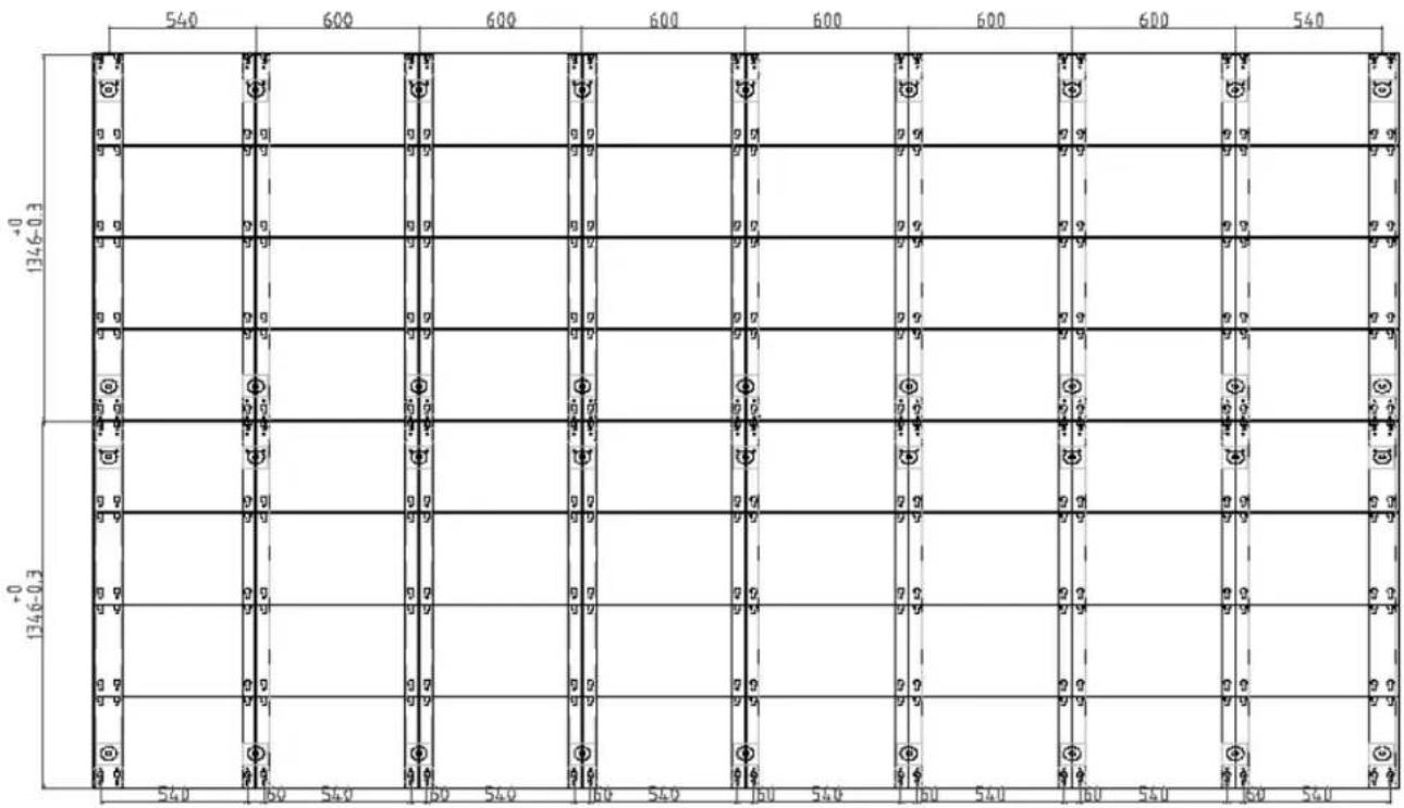
bar
| Level | Value | |-------|-------| | Top | 540 | | Top | 600 | | Top | 600 | | Top | 600 | | Top | 600 | | Top | 600 | | Top | 600 | | Top | 540 | | Top | 600 | | Top | 600 | | Top | 600 | | Top | 600 | | Top | 600 | | Top | 600 | | Top | 540 | | Top | 600 | | Top | 600 |- If the tiles are being mounted on an external support structure, make sure the external support structure is anchored to the wall and/or to the floor.
The design and anchoring of the LED display support structure is not the responsibility of Christie. Contact a Christie representative for support structure design options.
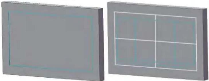
- Determine where the vertical mounting poles should be installed.
Find and mark the border of the display area with tape measure.
natural_image
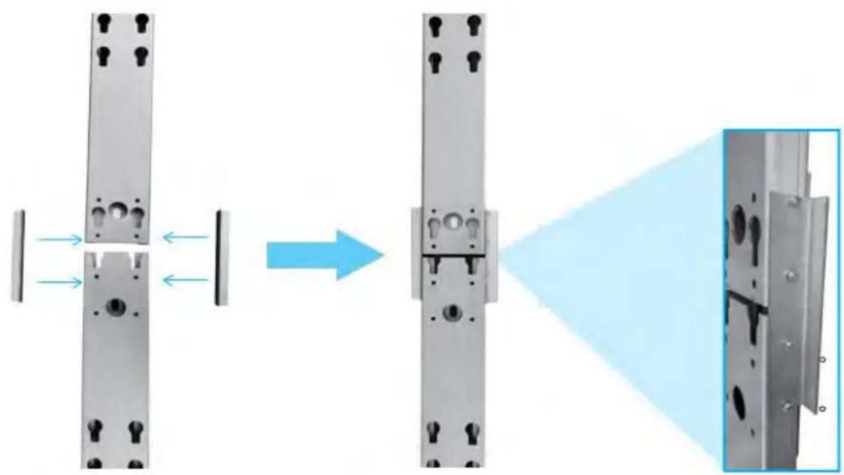
Two 3D-rendered rectangular panels with internal grid patterns, no text or symbols present- When the vertical mounting poles must be stacked on top of each other, Christie recommends assembling the top and bottom poles together before mounting them on the support surface.
a. Align the top and bottom vertical mounting poles.
b. Attach the side connecting plates to keep the vertical mounting poles together.
Each connecting plate needs four screws.
To do this, lay the vertical mounting poles on the floor and attach the side connecting plates as shown below:
natural_image
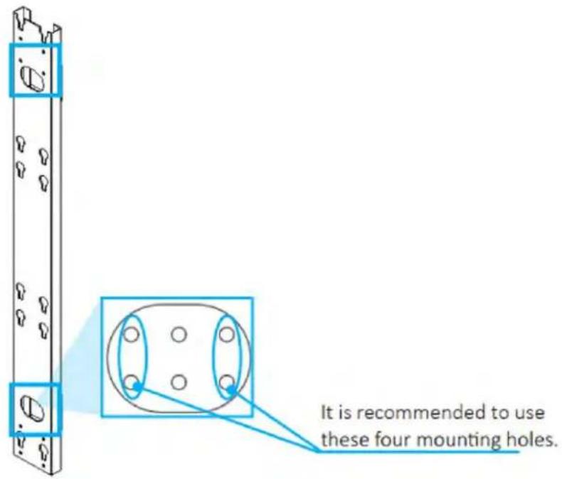
Diagram showing a mechanical assembly process with arrows indicating transformation from two vertical components to a final assembled view (no text or symbols present)- Attach the first vertical mounting poles to the support surface using four screws (two in the top slot and two in the bottom slot).
- Use the mounting template to align the second vertical mounting pole.
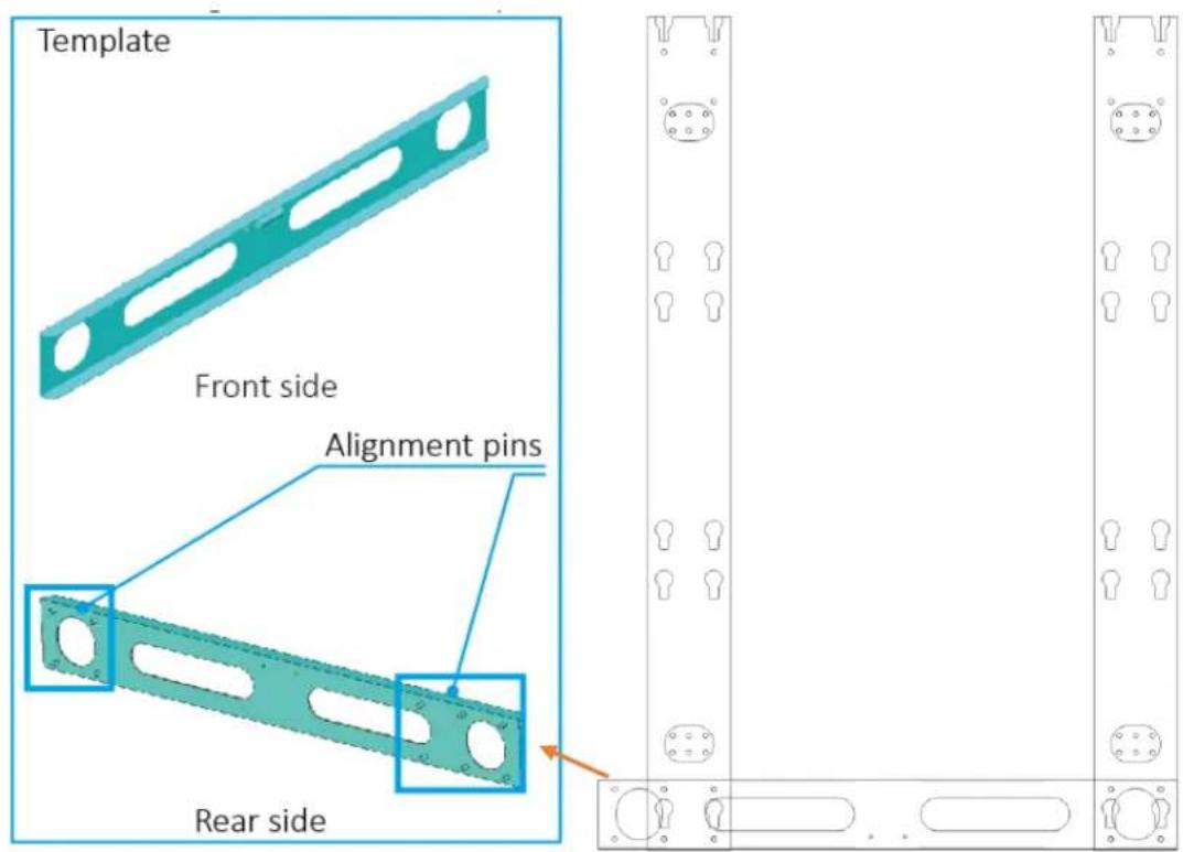
-
Attach the second vertical mounting pole to the support surface as shown in step 3.
-
Repeat steps 5 and 6 to mount each adjacent vertical mounting pole.
The correct distance for the first and last vertical mounting pole is shorter than between all other poles, as shown below:
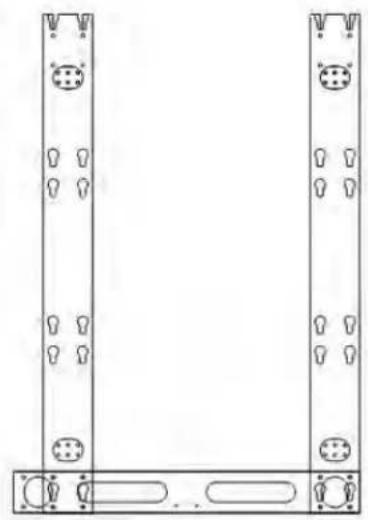
natural_image
Pure technical line drawing of two vertical structural components with circular features and mounting holes, no text or symbols present.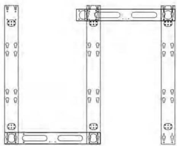
natural_image
Technical line drawing of two vertical structural components with mounting holes and circular features (no text or symbols)Mounting the tiles
Install the tiles in the array row by row. Do not attempt to construct the array column by column.

Warning! If not avoided, the following could result in death or serious injury.
- External support for a display wall must be designed and implemented by a Christie qualified installer and must comply with local area regulations and safety standards.
- All display walls must have permanent external supports. The amount of external support required depends on the size of the display wall.
-
A minimum of two people or appropriately rated lift equipment is required to safely lift, install, or move the product.
-
If present, remove the metal plates that cover all the external pass-through holes in the tile chassis, including the plate surrounding the power and data ports.
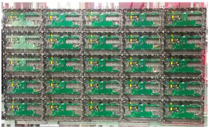
natural_image
Grid of green electronic circuit boards with visible traces and connectors, no text or symbols present.- Attach the first tile in the center of the bottom row to the vertical mounting poles on the four mounting points.
- To install the second tile in the row, repeat steps 1 and 2.
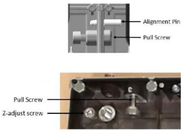
- Insert the alignment pins between the first tile chassis and the second tile chassis, then use the pull screw to bring the first and second chassis completely flush to each other.
a. Use the Z-adjust screw to align the chassis for perfect flatness.
b. To determine what adjustments are needed on the tile chassis, it may be necessary to install and remove the LED modules multiple times.
- For all the remaining tiles in the bottom row, repeat steps 1 to 4.
- After the bottom row is installed and all tiles are correctly aligned, repeat steps 1 to 5 for the remaining rows.
Make sure the M6 screws have at least three full threads engaged into the tile.
Connecting the data source cables
- Connect the Ethernet jumper-cables between the tiles in the array.
As Ethernet communication is bi-directional, this connection can be made from top-to-bottom in the column or tiles, or vice versa. You can also connect data cables horizontally across the row of tiles but a longer Ethernet jumper-cable is needed.
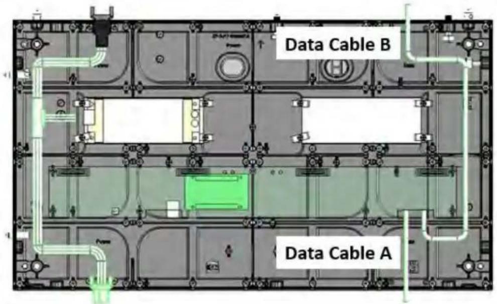
- Connect an Ethernet cable from each Ethernet output port on the controller to the corresponding tile according to the connection diagram provided in the design package for your project.
Connecting the power cables
Connect the power cables between the tiles in the array, column by column.

Caution! If not avoided, the following could result in minor or moderate injury.
- SHOCK HAZARD! The line cord has a maximum power carrying capability. For the maximum number of tiles that may be connected per daisy chain when connecting to the power supply, refer to the product specifications.
- Connect the power cable to the next tile in the array.
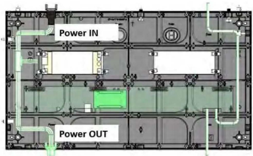
- Connect the main power cable from the wall outlet to the top tile in each column of tiles in the array. Power cables must be connected top to bottom and only vertical connection within a column is possible.
Installing the LED modules
For the steps described below, the smaller size LED module of 0.9 mm pixel pitch is shown as the example.
- Check the sticker on each LED module to identify the corresponding cabinet number and correct position within the cabinet.
Install the LED module according to the ordering chart shown below:
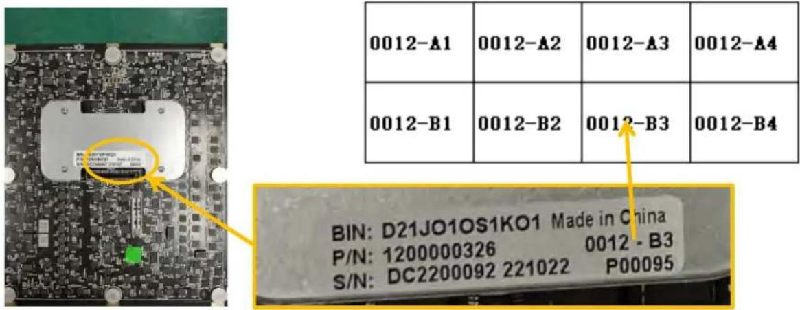
The meaning of each of the items on the sticker above is shown in the table below:
BIN: Tube type
P/N: Module material code
S/N: Order No. + Date
0012-B3: Cabinet No.-Module No.
P00095: module file serial No.
253590P00000095: .db file name (Photometry data file) :
OP No.+module file serial No.
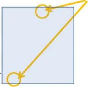
- Line up the LED module with the alignment pins in the alignment recesses, making sure the arrow on the back of the LED module is pointing up.
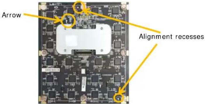
- Set the LED module into place on the alignment recesses.
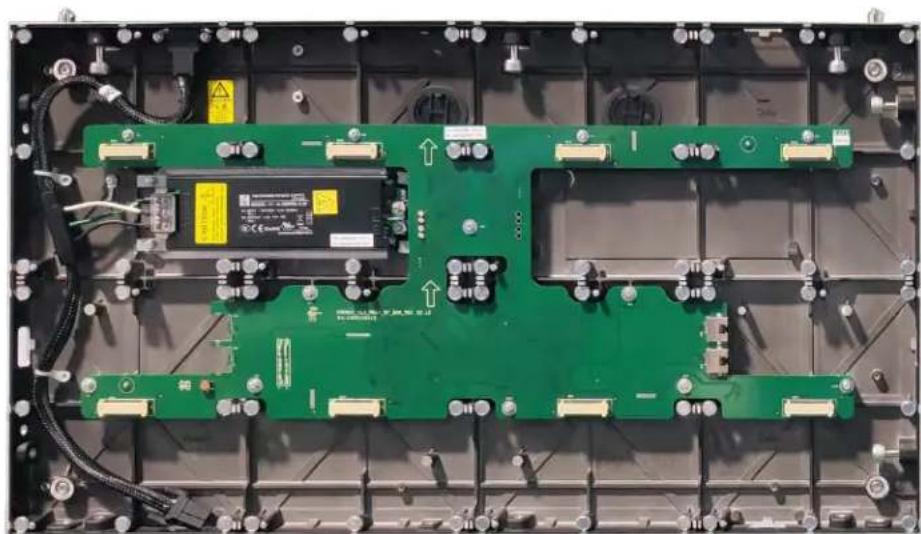
natural_image
Interior view of an electronic device with green circuit board and wiring (no visible text or symbols)- If the LED module does not fit into its position or if there is a gap between the LED modules of two tiles, adjust the spacing between the tiles.
Powering on the array
Turn on each component in the array in the order below.
- Start the computer that is the video source.
- Plug the tiles into the wall.
- Turn on the controller.
a. On the rear of the controller, turn the power switch to On.
b. On the front of the controller, select Power.
Alignment pins
natural_image
Simple geometric diagram showing a yellow line connecting two circles inside a square (no text or symbols)Powering off the array
Turn off each component in the array in the order below.
- Turn off the controller.
a. On the front of the controller, select Power.
b. On the rear of the controller, turn the power switch to Off.
- Power off the computer.
Connecting to video sources
An LED array requires a controller to display content on the tiles.
- Connect the data cable from the first tile in the array to the controller.
- Connect the HDMI or DVI output from the video source (computer or media player) to the appropriate input port on the controller.
The LED control unit behaves as two independent controllers, displaying 3840x2160 pixels at 30 Hz with each virtual controller. The images of both DVI1 and DVI2 input sources can be displayed on the tiles simultaneously but the inputs must be configured independently.
DVI1 corresponds to Ethernet ports 1 to 8 and DVI2 corresponds to Ethernet ports 9 to 16.
- Power on the array.
After the controller is connected and powered up, the video content is available as long as the video source is connected.
CHRISTIE
Regulatory
This product conforms to the latest regulations and standards related to product safety, environmental requirements, and electromagnetic compatibility (EMC).
Safety
- cTUVus per UL 60950-1 - Information Technology Equipment – Safety – Part 1: General Requirements
- IEC 60950-1 IEC/EN 60950-1 - Information Technology Equipment - Safety - Part 1: General Requirements
• EN 60950-1
• IEC 62471-1 - Photobiological safety of lamps and lamp systems
Electro-magnetic compatibility
Emissions
• FCC CFR47, Part 15, Subpart B, Class A - Unintentional Radiators
- CAN ICES-003 (A)/NMB-003 (A) - Information Technology Equipment (In Apparatus) - Limits and Methods of Measurement
• CISPR 32/EN 55032, Class A
• IEC 61000-3-2/EN61000-3-2: Limits for Harmonic Current Emissions
Immunity
• IEC 61000-3-3/EN61000-3-3
- IEC/EN61000
• IEC 61000-4-2/EN61000-4-2
• IEC 61000-4-3/EN61000-4-3
• IEC 61000-4-4/EN61000-4-4
• IEC 61000-4-5/EN61000-4-5
• IEC 61000-4-6/EN61000-4-6
• IEC 61000-4-8/EN61000-4-8
• IEC 61000-4-11/EN61000-4-11
- Installation and Setup Guide
- LED Display System
- Christie Core III Series
- NOTICES
- COPYRIGHT AND TRADEMARKS
- GENERAL
- WARRANTY
- PREVENTATIVE MAINTENANCE
- REGULATORY (if applicable)
- NOTATION
- Content
- Product overview 4
- Installation and setup....9
- Regulatory 21
- Product overview
- Important safeguards
- General safety precautions
- Power precautions
- Terminology
- Product documentation
- Related documentation
- Required tools
- Typical LED solution
- Cable and controller layout and design
- Installation and setup
- Installing an LED array from the front
- Installing the Vertical Mounting Poles
- Mounting the tiles
- Connecting the data source cables
- Connecting the power cables
- Installing the LED modules
- Powering on the array
- Powering off the array
- Connecting to video sources
- CHRISTIE
- Regulatory
- Safety
- Electro-magnetic compatibility
- Emissions
- Immunity
Brand : Christie
Model : Core III
Category : Monitor