Secure SUHD553-L - Monitor Christie - Free user manual and instructions
Find the device manual for free Secure SUHD553-L Christie in PDF.

| Product Type | Professional LED Monitor |
| Model | Secure SUHD553-L |
| Brand | Christie |
| Screen Size | 55 inches (diagonal) |
| Resolution | 3840 x 2160 (4K UHD) |
| Panel Type | LED-backlit LCD |
| Brightness | 500 cd/m² (typical) |
| Contrast Ratio | 4000:1 (typical) |
| Viewing Angle | 178° horizontal / 178° vertical |
| Inputs | HDMI 2.0, DisplayPort 1.2, DVI-D, VGA, USB |
| Power Consumption | 150W (typical), <0.5W standby |
| Dimensions (W x H x D) | 1240 x 715 x 85 mm (without stand) |
| Weight | 25 kg (without stand) |
| VESA Mount | 400 x 400 mm |
| Operating Temperature | 0°C to 40°C |
| Cleaning Instructions | Use a soft, dry cloth. Do not use liquid cleaners or abrasives. |
| Safety Features | Overheat protection, Kensington lock slot, RoHS compliant |
| Spare Parts & Repairability | Internal power supply, main board, panel. Repairs by authorized technicians only. |
| Warranty | 3 years limited warranty |
Frequently Asked Questions - Secure SUHD553-L Christie
User questions about Secure SUHD553-L Christie
0 question about this device. Answer the ones you know or ask your own.
Ask a new question about this device
Download the instructions for your Monitor in PDF format for free! Find your manual Secure SUHD553-L - Christie and take your electronic device back in hand. On this page are published all the documents necessary for the use of your device. Secure SUHD553-L by Christie.
USER MANUAL Secure SUHD553-L Christie
Secure Series II LCD
Panels
CHRISTIE®
NOTICES
COPYRIGHT AND TRADEMARKS
Copyright © 2023 Christie Digital Systems USA, Inc. All rights reserved.
All brand names and product names are trademarks, registered trademarks or trade names of their respective holders.
GENERAL
Every effort has been made to ensure accuracy, however in some cases changes in the products or availability could occur which may not be reflected in this document. Christie reserves the right to make changes to specifications at any time without notice. Performance specifications are typical, but may vary depending on conditions beyond Christie's control such as maintenance of the product in proper working conditions. Performance specifications are based on information available at the time of printing. Christie makes no warranty of any kind with regard to this material, including, but not limited to, implied warranties of fitness for a particular purpose. Christie will not be liable for errors contained herein or for incidental or consequential damages in connection with the performance or use of this material. Canadian manufacturing facility is ISO 9001 and 14001 certified.
For the most current technical documentation and office contact information, visit www.christiedigital.com.
WARRANTY
Products are warranted under Christie's standard limited warranty, the details of which are available at https://www.christiedigital.com/help-center/warranties/ or by contacting your Christie dealer or Christie.
PREVENTATIVE MAINTENANCE
Preventative maintenance is an important part of the continued and proper operation of your product. Failure to perform maintenance as required, and in accordance with the maintenance schedule specified by Christie, will void the warranty.
REGULATORY (if applicable)
The product has been tested and found to comply with the limits for a Class A digital device, pursuant to Part 15 of the FCC Rules. These limits are designed to provide reasonable protection against harmful interference when the product is operated in a commercial environment. The product generates, uses, and can radiate radio frequency energy and, if not installed and used in accordance with the instruction manual, may cause harmful interference to radio communications. Operation of the product in a residential area is likely to cause harmful interference in which case the user will be required to correct the interference at the user's own expense. Changes or modifications not expressly approved by the party responsible for compliance could void the user's authority to operate the equipment.
CAN ICES-3 (A) / NMB-3 (A)
The product is designed and manufactured with high-quality materials and components that can be recycled and reused. This symbol means that electrical and electronic equipment, at their end-of-life, should be disposed of separately from regular waste. Please dispose of the product appropriately and according to local regulations. In the European Union, there are separate collection systems for used electrical and electronic products.
If printing this document, consider printing only the pages you need and select the double-sided option.
Please help us to conserve the environment we live in!
Content
Unpacking and handling the display....6
Unpacking the panel 6
Handling and mounting guidelines for extreme narrow bezel series panels....7
Cleaning the panel....7
Product documentation....7
Related documentation....8
Important safeguards 8
General Safety precautions....8
Electrical specifications....9
Environmental specifications 9
Symbols....10
Introduction....11
Product overview....11
Key features....11
Parts List 12
Technical support 12
Controls and functions 13
Display-at-a-glance....13
In/Output panel 15
Remote control unit 20
Installing the display....22
Remote control 22
Notes on batteries....22
Notes on remote control operation 22
Quick setup: workflow....23
Installation considerations 23
Ambient light....23
Ambient heat....23
Ventilation considerations....23
Mounting the display....24
Connections to the display 24
Connecting a control system or PC....25
RS232 connection 25
IR Receiver kit connection 25
Connecting source components to the display 26
DisplayPort source connection 26
HDMI source connections 27
Turning on the power 28
Avoiding image retention....28
Avoid static content 29
Changing the on-screen display language 29
Operation 30
Using the on-screen menus....30
Picture settings 34
Determining the image input 34
Setting panel backlight 34
Selecting....34
Picture Mode 34
Setting image contrast....34
Setting image brightness 35
Setting image color 36
Setting image sharpness....36
Setting image color temperature....37
Enabling or disabling HDR10....37
Resetting the picture values 37
Sound settings....38
Setting the audio input 38
Adjusting the volume....38
Adjusting the sound balance....38
OSD settings....39
Specifying the language....39
Turning off the on-screen display menus....39
Determining the on-screen display position 39
Setup settings....40
Enabling Power Save 40
Determining how the display goes into Power Off Mode 40
Selecting the interface 40
Powering the display on or off using a....41
CEC command 41
Setting the OPS/HDMI4 EDID 41
Determining the gamma curve....41
Enabling or disabling the active source 41
Enabling or disabling Low Latency Mode....41
Performing a factory reset....42
Presets....42
Applying presets....42
Editing presets....42
Storing multiple window presets 42
Resetting presets....43
Preset Edit 43
Selecting an input mode 44
Viewing status information....45
Open Plugable Specification (OPS) 45
Supported timings....47
Updating the Scaler firmware using USB 49
Network guide 51
Setting the connection 51
PC Setting 52
Completing a ping test 52
Connecting a web server 52
Upgrading the Ethernet or Scaler firmware....53
Connecting to the Crestron-X-panel program 53
Connecting to the Crestron-Roomview program 54
Controlling monitor settings....54
Maintenance and troubleshooting.... 55
Maintenance 55
Troubleshooting....55
Unpacking and handling the display
Learn how to remove the display panel from the packaging and how to handle the display panel.
Unpacking the panel
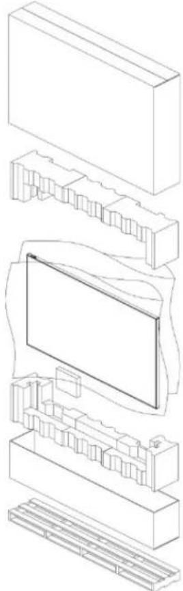
Learn how to remove the panel from the packaging. Each LCD panel is packed inside a box carton. To protect the panel during transportation, additional packing material has been placed within the carton.
natural_image
Exploded view diagram of a computer monitor showing internal components (no text or labels)Before unpacking, prepare a stable, level and clean surface near a wall outlet.
- Set the box in an upright position and pull out the white carton locks.
- Lift up the top cover carton.
- Remove the polybag before removing the display from the bottom tray carton.
- Remove any additional packaging, such as protective stickers, from the display panel.
Handling and mounting guidelines for extreme narrow bezel series panels
Follow these best practices when handling and mounting extreme narrow bezel panels:

Notice. If not avoided, the following could result in property damage.
- When moving the panel, always use the handles. Do not carry the frame.
- Do not twist, bend, or tilt the panel.
- Do not apply excessive force to the sides of the bezel when mounting the panel or pushing into its locked position.
• Always handle the display panel from the sides or handles.
Follow the following guidelines before removing the panel from the packaging:
• To verify normal operation before handling, power on the panel in the packaging.
• Always use the handles to pick up and carry the panel.
- Leave the panel in the box until the mount is on the wall and you are ready to install the panel.
- To avoid putting undue stress on the panel when mounted, make sure the mount is square, flat, and level.
- Do not rest panels on top of a lower panel.
- When inserting the panel into the wall, pay close attention to adjacent panels.
• Make sure there is a minimum of 0.5 mm between mounted panels to allow for thermal expansion.
Cleaning the panel
Learn how to clean the display panel.
-
After disconnecting the power cable, wipe contaminated parts and each part of the product screen lightly with a dry and soft cloth.
-
Do not use a liquid, spray cleaners, or any abrasive cleaners to clean the LCD panel.
- Washing with various cleaning agents, brighteners, abrasives, waxes, benzene, alcohol, solvent, surface active agent, may damage the surface of the product.
Product documentation
For installation, setup, and user information, see the product documentation available on the Christie website. Read all instructions before using or servicing this product. To access the documentation from the Christie website:
- Go to this URL: https://bit.ly/2VccFTr
- Scan the QR code using a QR code reader app on a smartphone or tablet

- On the product page, select the model and switch to the Downloads tab.
Related documentation
Additional information on the LCD panels is available in the following documents.
- SUHD863-L, SUHD753-L, SUHD653-L, SUHD553-L LCD Panels Product Safety Guide (P/N: 020-001778-XX)
- SUHD863-L, SUHD753-L, SUHD653-L, SUHD553-L LCD Display Panels External Commands (P/N: 020-001915-XX)
• SUHD553-L LCD Panels Service Guide (P/N: 020-001850-XX)
• SUHD653-L LCD Panels Service Guide (P/N: 020-001851-XX)
• SUHD753-L LCD Panels Service Guide (P/N: 020-001876-XX)
• SUHD863-L LCD Panels Service Guide (P/N: 020-001887-XX)
Important safeguards
To prevent personal injury and to protect the device from damage, read and follow these safety precautions.
General Safety precautions
Observe these important safety rules to avoid personal injury or damage to the product.

Warning! If not avoided, the following could result in death or serious injury.
• Christie products must be installed and serviced by Christie qualified technicians.
- Two people or adequately rated lifting equipment are required to safely lift, install, or move the product.
- FIRE HAZARD! Do not install near any devices that produce heat such as amplifiers, radiators, heat registers, or stoves.
- SHOCK HAZARD! Only use the AC power cord provided with the product or recommended by Christie.
- SHOCK HAZARD! Disconnect the product from AC before servicing, cleaning, removing components, or opening any enclosure.
- FIRE HAZARD! Do not use a power cord that appears damaged.
- SHOCK HAZARD! Do not attempt operation if the AC supply is not within the specified voltage and power range, as specified on the license label.
- SHOCK HAZARD! The AC power cord must be inserted into an outlet with grounding.
• Always connect the ground first to reduce shock hazard.
- TRIP OR FIRE HAZARD! Position all cables where they cannot contact hot surfaces, be pulled, be tripped over, or damaged by persons walking on or objects rolling over the cables.
- Do not drop the panel (even a short distance), or apply pressure to the sides of the bezel. The small size of the bezel, means there is reduced protection of the LCD glass and components. Dropping the panel or applying unnecessary force to the sides of the bezel will result in permanent damage.
- To avoid serious injury and/or serious damage to the LCD panel, moving the panel requires at least four people.
- Extreme care must be taken when pushing the mounted display into its locked position. Always handle the display on the opposing corners of the frame to avoid direct contact with the LCD glass.

Caution! If not avoided, the following could result in minor or moderate injury.
• Do not tilt the product more than ±15 degrees.
• Use the handles when moving the shipping package.
- Do not twist, bend, or tilt the panel.

Notice. If not avoided, the following could result in property damage.
• Install the product at least 10 cm from the wall.
- Do not install in locations where has vibration or in an unstable position as the product may fall and cause damage.
- Do not install in places where dirt, moisture, smoke, much water or rain water can reach the product.
- Avoid exposure to direct sunlight and do not place near hot objects such as a fire or heater heat. This may cause a fire or shortening the product life.
- Do not place heavy objects on the product.
• Always provide proper ventilation for the product to prevent overheating.
• Do not place the screen on a hard surface.
Electrical specifications
Rate input voltage:
• SUHD553L: 100 to 240 V, 50/60 Hz, 3.1 to 1.3 A
• SUHD653L: 100 to 240 V, 50/60 Hz, 2.6 to 1.1 A
• SUHD753L: 100 to 240 V, 50/60 Hz, 2.9 to 1.2 A
• SUHD863L: 100 to 240 V, 50/60 Hz, 4.1 to 1.7 A
Environmental specifications
Learn about the environmental specifications:
- Operating temperature:
• 0 to 40°C (32 to 104°F)
• 20 to 80% RH
• Storage temperature:
-20 to 60°C (-4 to 140°F)
- 5 to 90% RH
Symbols
The following symbols are used on the panels:
I/O: On or off
• \~: Alternating current
Introduction
This guide describes how to install, set up and operate the Secure Series II LCD Panels. Throughout this guide, the Secure Series II LCD Panels are referred to collectively as the display.
Christie prepared this manual to help end users get the most out of the display.
Christie has made every effort to ensure that this guide is accurate as of the date it was printed. However, because of ongoing product improvements and customer feedback, it may require updating without notice from time to time.
Product overview
The Secure Series II LCD Panels a 86", 75", 65", 55" high performance UHD display featuring 450(55": 500) nits brightness, advance input connectivity and multi-source viewing.
Key features
The display offers these key features and benefits:
• Ultra-HD native resolution: 3840x2160 (16:9 native aspect ratio)
• High Brightness: Up to approximately 450 (55": 500) nits
• Ultra-wide 178-degree viewing angle
- Modern connectivity with DisplayPort 1.2, HDMI2.0 inputs with high-bandwidth digital content protection (HDCP2.2)
• Supported OPS (Open Pluggable Specification) slot:
- HDMI2.0
- DisplayPort 1.2
- RS232
- Display Area:
• 86": 1895.04 mm X 1065.96 mm (horizontal X vertical)
• 75": 1649.664 mm X 927.936 mm (horizontal X vertical)
• 65": 1428.664 mm X 844.4 mm (horizontal X vertical)
- 55": 1209.60 mm X 680.40 mm (horizontal X vertical)
- Bezel Width for 86", 75", 65", 55": 18.8mm
• Pixel Arrangement: RGB Stripe
- Pixel Pitch: 86":
• 0.4935 mm × 0.4935 mm
• 75": 0.429 mm X 0.429 mm
• 65": 0.372 mm × 0.372 mm
- 55": 0.105 mm X 0.105 mm
• Display orientation: Landscape
• Surface treatment:
• 86", 75": AGLR (anti-glare low reflection), hard coating(2H), haze 28%
- 65": AGLR (anti-glare low reflection), hard coating(2H), haze 3%
- 55": AGLR (anti-glare low reflection), hard coating(3H), haze 25%
- Latency: 8ms
Parts List
Your display is shipped with the following items. If any items are missing or damaged, contact your dealer or Customer Service.
• SUHD863-L/SUHD753-L/SUHD653-L/SUHD553-L LCD panel
• IR remote controller unit and battery (AAA Size x 2 each)
• RS232 cable (length 1800 mm)
• HDMI cable (length 3000 mm)
• External IR Receiver kit
- Screw (M3x6)—2 each
Technical support
• North and South America: +1-800-221-8025 or Support.Americas@christiedigital.com
• Europe, Middle East, and Africa: +44 (0) 1189 778111 or Support.EMEA@christiedigital.com
• Asia Pacific (support.apac@christiedigital.com):
• Australia: +61 (0)7 3624 4888
• China: +86 10 6561 0240
• India: +91 (80) 6708 9999
• Japan: 81-3-3599-7481
• Singapore: +65 6877-8737
• South Korea: +82 2 702 1601
• Christie Professional Services: +1-800-550-3061 or NOC@christiedigital.com
Controls and functions
The appearance of actual components may differ from the image shown.
Display-at-a-glance
The illustration below shows the key display components, and the paragraphs that follow describe them.
SUHD863-L
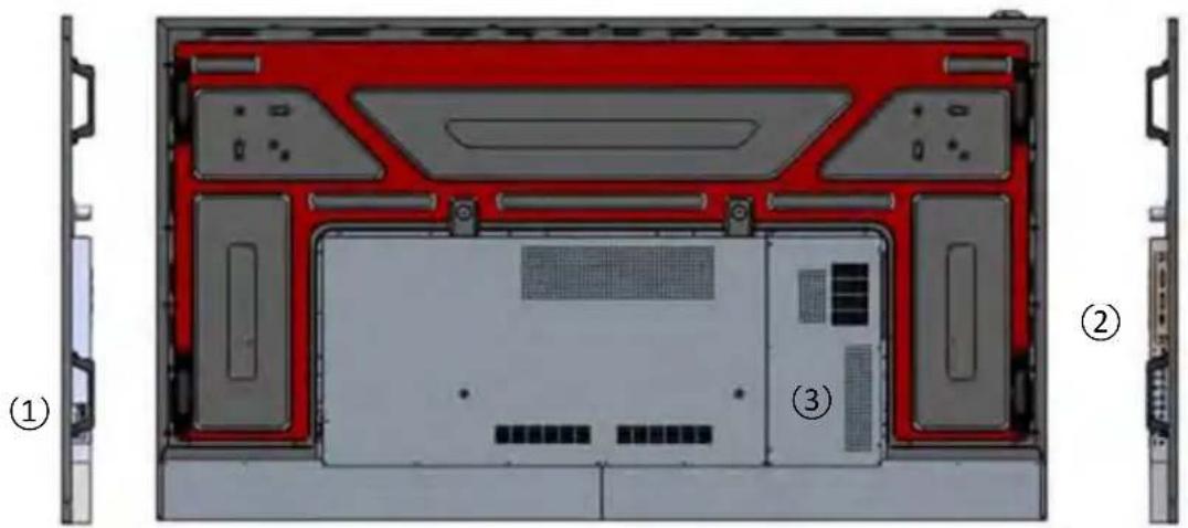
natural_image
Diagram of a computer chassis showing front, back, and internal components (no text or labels)SUHD753-L
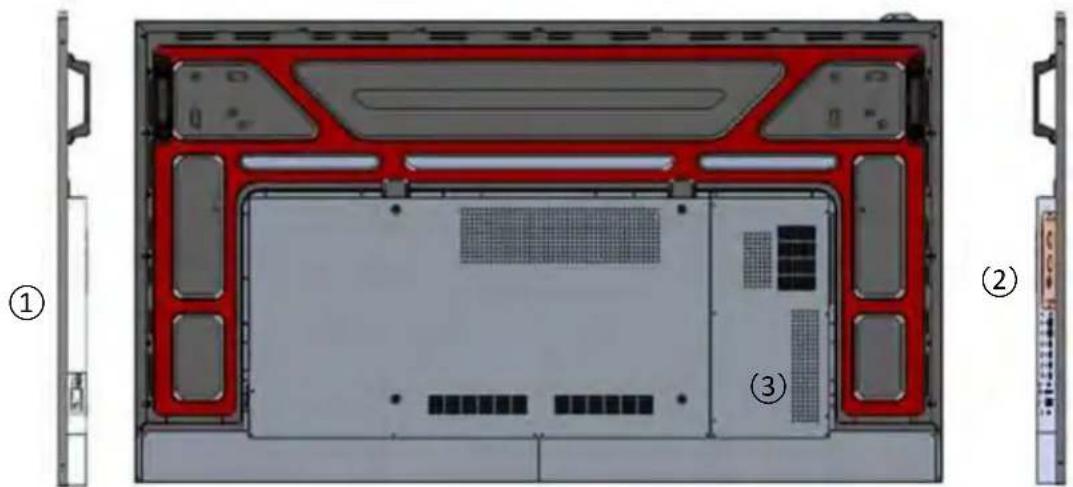
SUHD653-L
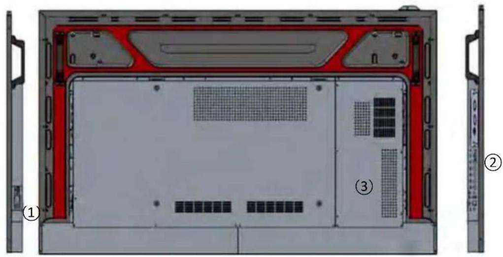
SUHD553-L
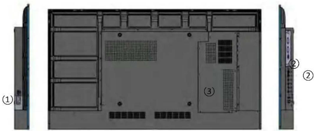
Component Description
| 1 Main power | Connects or disconnects the display panel from the AC power source.100 to 240 VAC, 50/60Hz | ||
| 2 Input port and IR receiver/power status LED | Power status LED | On | No color |
| Standby Red | |||
| Power Save | Red blinking | ||
| 3 Keypad | Use the keypad instead of the remote control unit to operate the on-screen display (OSD) controls.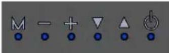 The keypad operates as follows The keypad operates as follows | ||
| On/ Standby ( ) | Use the keypad instead of the remote control unit to operate the on-screen display (OSD) controls.The keypad operates as follows:Select once to toggle from standby mode to on mode.Select it again to return to standby mode. | ||
| ▲ (SOURCE) | To choose a source, select the ▲(SOURCE) button repeatedly (with no menus visible on-screen).When a menu is visible on-screen, this button operates identically to the up-arrow. | ||
| ▼ | When a menu is visible on-screen, this button operates identically to the down-arrow button on the display remote control unit. | ||
| + | Select to increase the volume.When a menu is visible on-screen, this button operates identically to the right-arrow (or SEL) button on the display remote control unit. | ||
| - | Select to decrease the volume.When a menu is visible on-screen, this button operates identically to the left-arrow button on the display remote control unit. | ||
| M (MENU) | Select to display the on-screen display (OSD) or to exit the on-screen display and return to the previous one. | ||
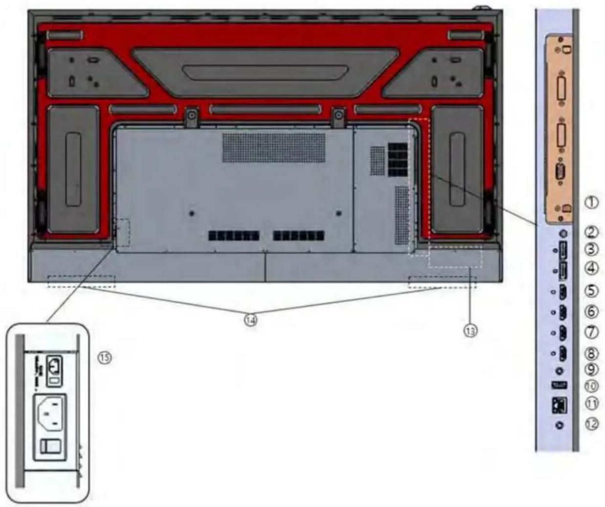
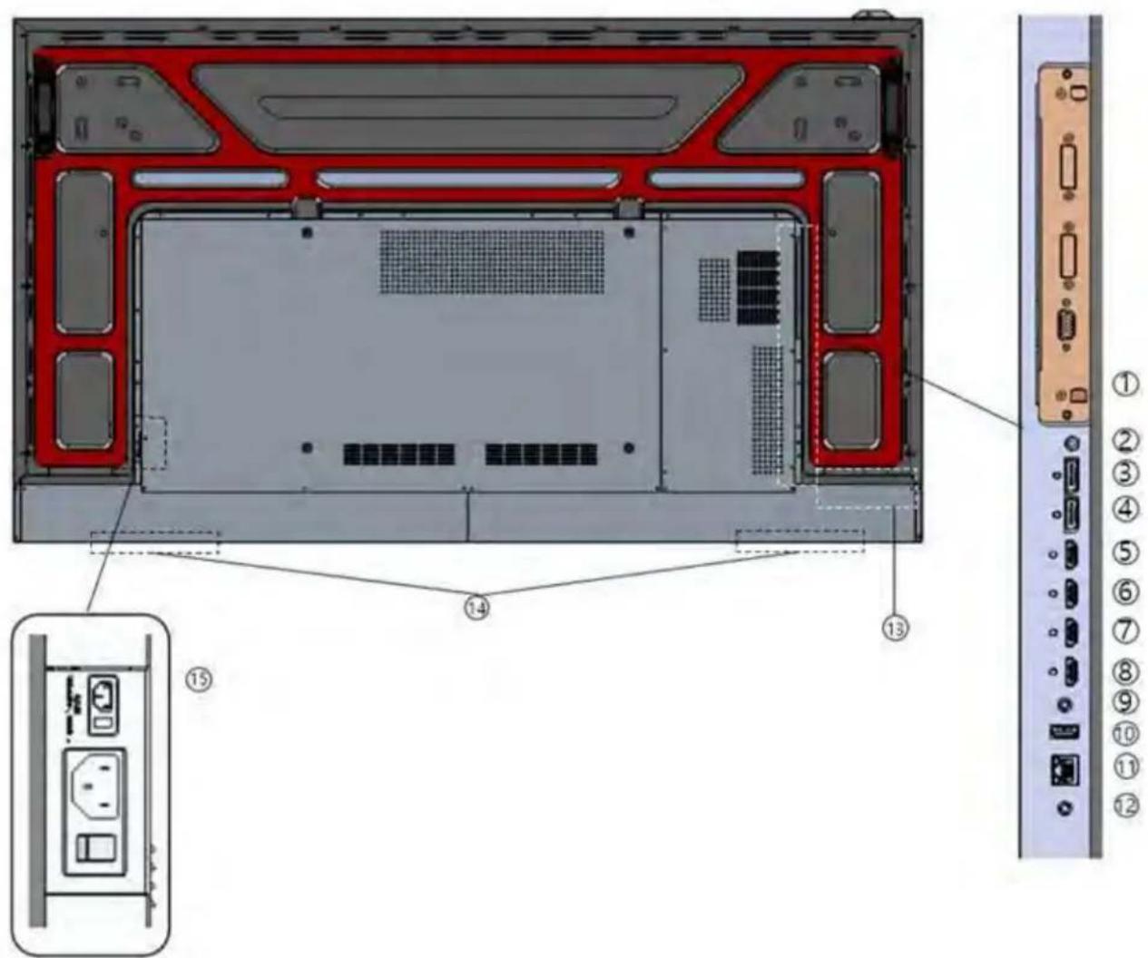
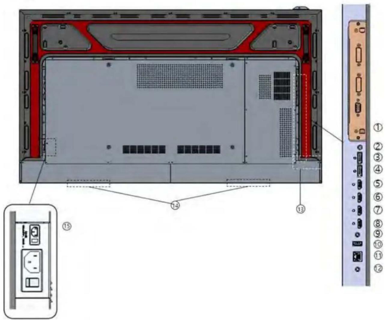
In/Output panel
The illustration below shows the display input panel.
SUHD 863-L
SUHD 753-L
SUHD 653-L
SUHD 553-L
| Component Description | |
| 1 OPS Slot (optional) | Connect the Open Pluggable Specification (OPS) PC |
| 2 IR In (3.5phi 4pole) | Connect the external IR receiver kit. |
| 34 DP1~2 In | Connect the DisplayPort 1.2 video and audio input. |
| 5678 HDMI 1 to 4 In | Connect the HDMI 2.0 video & audio input. |
| 9 RS232C In (3.5phi 3pole) | Connect the RS232 input cable with control device. |
| 10 Service In (USB A type) | Connect with USB device for software update. |
| 11 Ethernet In | Connect the Ethernet input cable with control device. |
| 12 Audio Out (3.5phi 3pole) | Connect the Audio Out to your Audio In on the audio system. |
| 13 OSD Key | Connect the Open Pluggable Specification (OPS) PC |
| 14 Internal Speaker (15W x 2ea) | Connect an internal speaker. |
| 15 AC Power | Connect to AC power. |
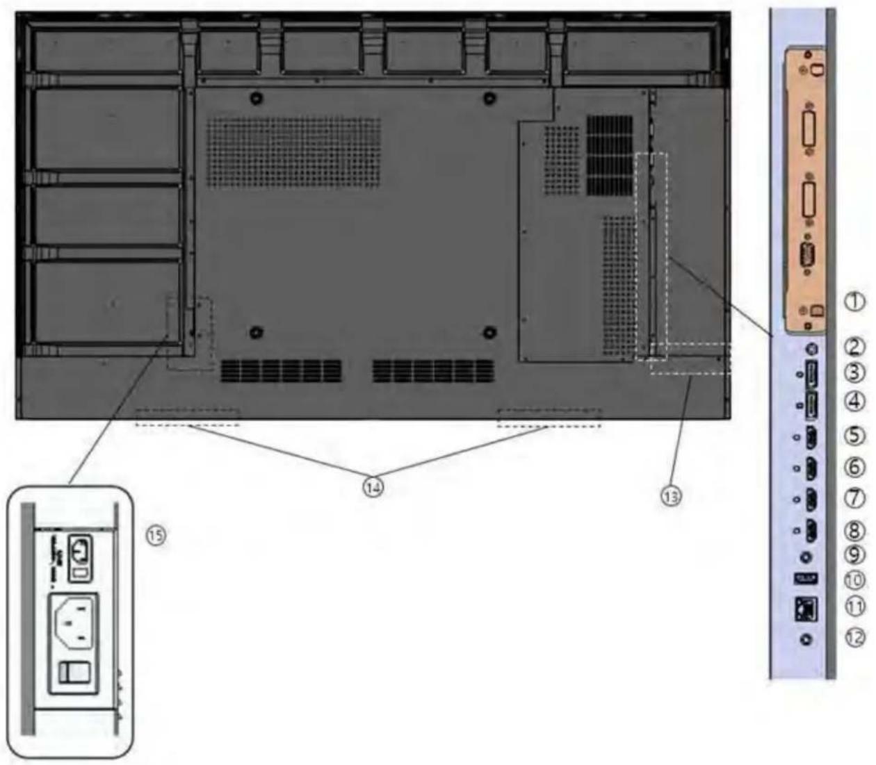
Remote control unit
The illustration below shows the display remote control and the table that follows describes its functionality.
| Label Description | |
| ↓ | Turns on or off the product |
| SOURCE | Selects a connected source device |
| ▲ | Moves to the up menu |
| ▼ | Moves to the down menu |
| SEL | Confirms a menu selection |
| ◀ or - | Decreases the sound volume or move to the left menu |
| ▶ or + | Increases the sound volume or move to the right menu |
| MENU | Opens the product on-screen menu system. When the menu system is already open, selecting this button chooses the previous submenu. |
| INFO | Provides source and resolution information |
| MUTE | Turns off the sound |
| 1 | Direct Key Preset 1 |
| 2 | Direct Key Preset 2 |
| 3 | Direct Key Preset 3 |
| 4 | Direct Key Preset 4 |
| 5 | Direct Key Preset 5 |
| 6 | Direct Key Preset 6 |
| 7 | Direct Key Preset 7 |
| 8 | Direct Key Preset 8 |
| 9 | Direct Key Preset 9 |
| 0 | Direct Key Preset 10 |
Installing the display
Installation of the display must be performed by a qualified installation specialist.
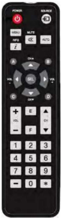
Remote control
The appearance of actual components may differ from the image shown. To install batteries in the remote control:
- Press the tab on the battery case and open it.
- Insert the battery (1.5V AAA) into the battery case.
- Insert the battery case until clack sounds.
natural_image
Two views of a remote control device showing internal components and directional arrows (no text or symbols)Notes on batteries
• Make sure the battery polarities are correct when installing the batteries.
- If you not using the remote control for a long time, remove the batteries to avoid damage from battery leakage.
- Do not expose batteries to excessive heat such as sunshine, fire, or so on.
Notes on remote control operation
- Make sure nothing obstructs the infrared beam between the remote control and the IR receiver on the display.
- If the effective range of the remote control decreases, or it stops working, replace the batteries with new ones.
- The remote control may fail to operate if the infrared remote sensor is exposed to bright sunlight or fluorescent lighting.
Quick setup: workflow
The following provides a quick overview of the display installation process. Subsequent sections provide detailed instructions.
| Step | Procedure | Additional details |
| 1 | Mount the display(s) on a wall (optional). | Mounting the display on page 24 |
| 2 | Connect other external equipment to the display:• Automation/control system (RS232) | Connecting a control system or PC on page 25 |
| 3 | Connect signal sources to the display. | Connecting source components to the display on page 26 |
| 4 | Apply power to the display. | Turning on the power on page 28 |
| 5 | Change the on-screen display language. | Changing the on-screen display language on page 29 |
| 6 | Display calibration and adjust the following for each input:• Backlight• Contrast• Brightness• Color• Sharpness• Color temperature | Picture settings on page |
Installation considerations
Proper installation of your display ensures a satisfying viewing experience. Whether installing a temporary or permanent display, take the following into account to ensure your display performs optimally.
Ambient light
In general, minimize or eliminate light sources directed at the screen. Images may appear washed out and less vibrant if light, such as sunlight through a window or floodlight, directly strikes the screen.
Ambient heat
The display performs best and achieves longer life if operated in normal office environment conditions. The ambient temperature should be kept below 40^ C ( 95^ F). Keep the display away from heating and/or air conditioning vents.
Ventilation considerations
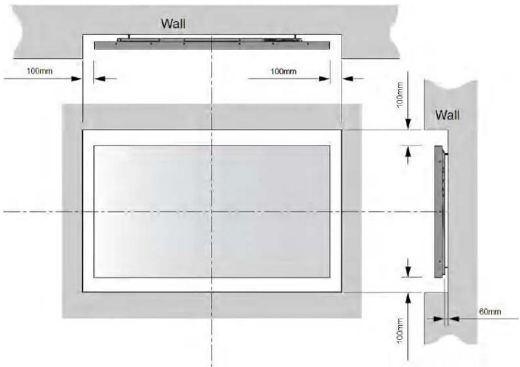
The appearance of components may differ from the image shown.
If mounting the display in an enclosure, leave sufficient space on all sides between it and surrounding objects, as shown below. This allows heat to disperse, maintaining the proper operating temperature.
Mounting the display
If you decide to wall-mount the display, make sure the wall-mount bracket is installed according to the instructions included with it. The wall must be capable of supporting a multiple weight factor of three times the weight of the display or be reinforced. Christie recommends a custom installation specialist doing this.

Use only the approved wall-mount kit designed for your display.
Connections to the display
The appearance of components may differ from the image shown. Connect the display to your video sources, external controller(s), if present, and AC power as follows.
When connecting your equipment:
• Turn off all equipment before making any connections.
• Use the correct signal cables for each source.
- For best performance and to minimize cable clutter, use high-quality cables, only as long as necessary to connect two devices. Do not use a 20-foot cable when a 6-foot cable suffices.
- Ensure the cables are securely connected. Tighten the thumbscrews on connectors that have them.
Connecting a control system or PC
Learn how to connect a control system or PC.
RS232 connection
Use a straight-through RS232 cable with a 3.5∅ stereo connector to connect a PC or control/automation system, if present, to the RS232 port on the display. For more information about using this connection, refer to API control manual document.
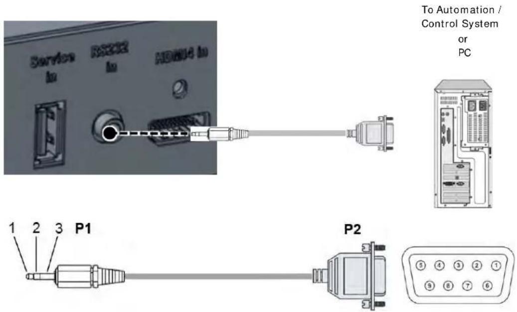
| P1 | P2 | |||||
| Stereo Tx | 1 | ← | 2 Rx DSUB9P | |||
| 3.5mm Rx | 2 | → | 3 Tx (Female) | |||
| Gnd | 3 | — | 5 Gnd | |||
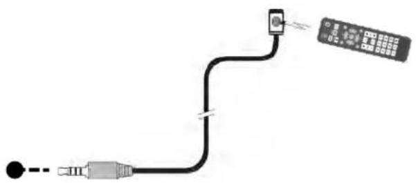
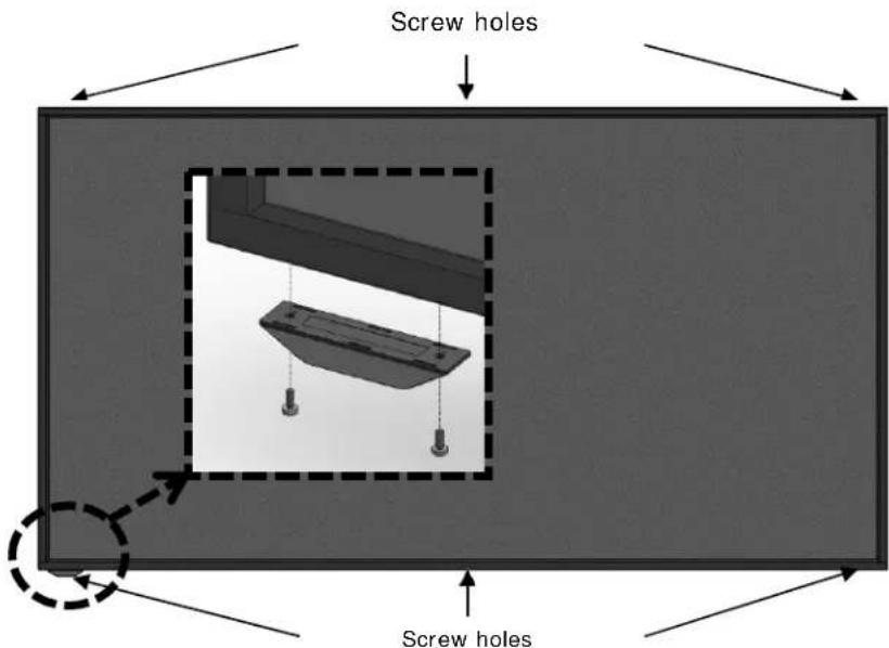
IR Receiver kit connection
Connect the provided External IR Receiver kit to the IR input as shown below.
natural_image
Pure electrical circuit lines without any symbols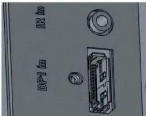
Fix the included external remote sensor to external remote sensor on the product by removing two screws on the top/bottom of the left/middle/right of the front, and re-using the screw.
Connecting source components to the display
Connect your video sources to the display as shown and described in the following sections.
DisplayPort source connection
Refer to Supported timings on page 47 for a list of compatible input signals. This display supports the VESA Display Data Channel (DDC) standard. This standard provides plug-and-play capability; the display and a VESA DDC-compatible computer communicate their setting requirements, allowing for quick and easy setup.
For plug-and-play to work correctly, turn on the display before you turn on the connected computer
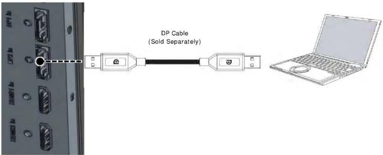
Purchase a certified Display Port cable. Otherwise, the picture may not display or a connection error may occur.
HDMI source connections
Use the HDMI inputs whenever possible. This ensures the highest video quality because the signal is carried in the digital domain throughout the entire signal path, from source component output into the display.
Refer to Supported timings on page 47 for a list of compatible input signals. This display supports the VESA Display Data Channel (DDC) standard. This standard provides plug-and-play capability; the display and a VESA DDC-compatible computer communicate their setting requirements, allowing for quick and easy setup.
For plug-and-play to work correctly, turn on the display before you turn on the connected computer.
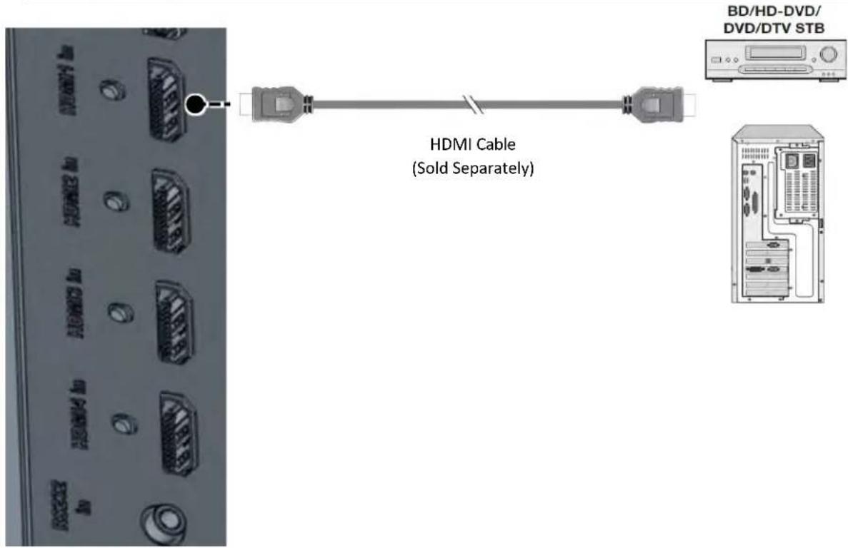
Purchase a certified HDMI cable. Otherwise, the picture may not display or a connection error may occur.
Turning on the power
Follow these steps to turn on the power.
- Connect the power cable of the display into an outlet with AC 100-240V 50/60Hz.
- Turn on the main AC power switch.
- If the power indicator is green, the screen turns on automatically.
- If the power indicator is red not green, select Power on the remote control or on the keypad to turn on the power.
Avoiding image retention
Christie recommends the following to prolong the life of the display:
- Operate the display within its rated ambient environment
• Operating temperature: 0 to 40°C (32 to 104°F)
• Relative humidity: 80%, maximum.

Notice. If not avoided, the following could result in property damage.
- Do not display static (non-moving) content on the display for long periods of time. This may cause image burn-in or image retention, which is not covered under warranty.
Avoid static content
To avoid static content, do the following:
- Display dynamic (moving) images whenever possible. Consider using a screen saver to avoid displaying continuous static (fixed) video content.
• Turn off the display when not in use.
Changing the on-screen display language
Select the language used for the menus and on screen display.
- To go to the menu, select Menu.
- From the main menu, select OSD.
- Select Language
- Select the preferred language.
- Exit the menu.
Operation
Learn how to operate the panel.
Using the on-screen menus
Complete the following steps to use the on-screen menus.
- To display the on-screen menus, select MENU on the remote control or built-in keypad.
- To select a submenu, use the ▲ and ▼ buttons to highlight it.
- To enter a submenu, select SEL.
- To select a menu item, use the ▲ and ▼ and buttons to highlight it.
- Select ▲ or ▼ to adjust the setting.
- To exit the menu, Select Menu.
The on-screen display menus are arranged hierarchically, as shown below. Depending on the selected input source and signal characteristics, some menu options may not be available.
| Level 1 | Level 2 | Level 3 | Values | Default |
| Picture | Input | HDMI1 | DP1DP2HDMI1HDMI2HDMI3HDMI4OPS-HDMIOPS-DP | HDMI1 |
| Backlight | 70 | 0 to 100 | 70 | |
| Picture Mode | Standard | StandardDynamicUser | Standard | |
| Contrast | 100 | 0 to 100 | 100 | |
| Brightness | 50 | 0 to 100 | 50 | |
| Color | 50 | 0 to 100 | 50 | |
| Sharpness | 50 | 0 to 100 | 50 | |
| Color Temperature | Normal | NormalWarmCoolStudio1Studio2User | Normal | |
| Red | — | 0 to 100 | Depends on model | |
| Green | — | 0 to 100 | Depends on model | |
| Blue | — | 0 to 100 | Depends on model | |
| HDR10 | Off | Off/ On | Off | |
| Picture Reset | — | — | Reset Picture menu | |
| Sound | Audio Select | — DP1 | DP2HDMI1HDMI2HDMI3HDMI4OPS-HDMIOPS-DP | Depends on current input |
| Volume | 50 | 0 to 100 | 50 | |
| Balance | 0 | -50 to +50 | 0 | |
| OSD Language English | EnglishSpanishFrenchRussianGermanItalianKorean | English | ||
| OPS/HDMI4 EDID UHD | UHDFHD | UHD | ||
| Gamma 2.2 2.2 | Standard | 2.2 | ||
| Auto Source Switch | Off | OffOn | Off | |
| Low Latency Mode | Off | OffOn | Off | |
| Factory Reset | — | — | Reset all menus | |
| Preset Apply/Edit | Preset1 | — Single/HDMI1 | ||
| Preset2 | — Dual1/HDMI1/HDMI2 | |||
| Preset3 | — Dual2/HDMI1/HDMI2 | |||
| Preset4 | — Dual3/HDMI1/HDMI2 | |||
| Preset5 | — Dual4/HDMI1/HDMI2 | |||
| Preset6 | — Triple1/HDMI1/HDMI2/HDMI3 | |||
| Preset7 | — Triple2/HDMI1/HDMI2/HDMI3 | |||
| Preset8 | — Triple3/HDMI1/HDMI2/HDMI3 | |||
| Preset9 | — Triple4/HDMI1/HDMI2/HDMI3 | |||
| Preset10 | — Quad/HDMI1/HDMI2/ | HDMI3/HDMI4 | ||
| Preset11 | — Single /DP1 | |||
| Preset12 | — Dual1 /DP1/DP2 | |||
| Preset13 | — Dual2 /DP1/DP2 | |||
| Preset14 | — Dual3 /DP1/DP2 | |||
| Preset15 | — Dual4 /DP1/DP2 | |||
| Preset16 | — Triple1/DP1/DP2/HDMI1 | |||
| Preset17 | — Triple2/DP1/DP2/HDMI1 | |||
| Preset18 | — Triple3/DP1/DP2/HDMI1 | |||
| Preset19 | — Triple4/DP1/DP2/HDMI1 | |||
| Preset20 | — Quad/DP1/DP2/ | HDMI1/HDMI2 | ||
| Preset Reset | — | |||
| Preset-Edit | Mode | — Single | Dual1Dual2Dual3Dual4Triple1Triple2Triple3Triple4Quad | Single |
| Window1 | — | DP1DP2HDMI1HDMI2HDM3HDMI4OPS-HDMIOPS-DP | — | |
| Window2 | — | — | ||
| Window3 | — | — | ||
| Window4 | — | — | ||
| LAN Setting | DHCP Off Off | On | Off | |
| IP Address | — 192.168.10.10 192.168.10.10 | |||
| Subnet Mask | — 255.255.255.0 255.255.255.0 | |||
| Gate Way | — 192.168.10.1 192.168.10.1 | |||
| DNS | — 168.126.63.1 168.126.63.1 | |||
| LAN Setting Reset | — | — | Reset the all Lan Setting | |
| ABOUT Model | — | The read-only System menu provides status information about the display | — | |
| Version | — | |||
| MAC | — | |||
| S/N | — | |||
| Window1 | — | |||
| Resolution | — | |||
| Window2 | — | |||
| Resolution | — | |||
| Window3 | — | |||
| Resolution | — | |||
| Window4 | — | |||
| Resolution | — | |||
Specifications are subject to change without notice to improve quality.
Picture settings
| Picture | Input | HDMI |
| Sound | Backlight | 70 |
| OSD | Picture Mode | Standard |
| Setup | Contrast | 100 |
| Presets | Brightness | 50 |
| LAN Setting | Color | 50 |
| About | Sharpness | 50 |
| Color Temperature | Normal | |
| Picture Reset | ||
Determining the image input
Set the type of input for the image.
- From the Picture Settings menu, select Input.
- Set the current input:
[DP1], [DP2,] [HDMI 1], [HDMI 2], [HDMI 3], [HDMI 4], [OPS-HDMI], [OPS-DP]
Setting panel backlight
The Backlight control changes the back light unit intensity of the panel.
- From the Picture Settings menu, select Backlight.
- Indicate the intensity of the backlight.
Selecting Picture Mode
Determine what mode you want to view the image.
- From the Picture Settings menu, select Picture Mode.
- Select ▲ or ▼ to choose one of two image quality presets (Standard or Dynamic) depending on the type of program material you are viewing.
These presets automatically adjust the other image settings for optimal image quality. You can adjust Brightness, Contrast, and other settings manually.
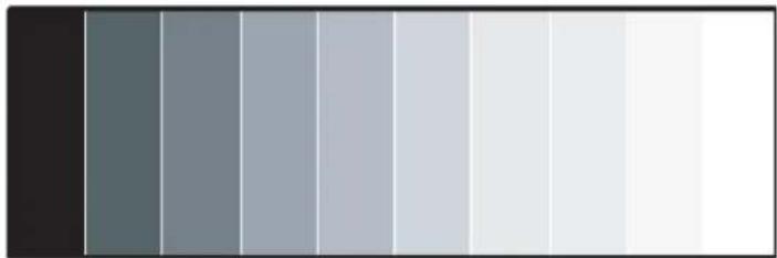
Setting image contrast
Contrast adjusts the white levels of the image.
- On your external test pattern source, select a stepped, gray-bar pattern like the one shown below.
natural_image
Gradient color bar transitioning from dark gray to white (no text or symbols)-
Select Contrast.
-
Select ▲ or ▼ to adjust the contrast to a point just below which the white rectangle starts to increase in size.
Setting image brightness
Determine the brightness of the image.
- On your external test pattern source, select a PLUGE pattern.
PLUGE is an acronym for Picture Line-up Generation Equipment.
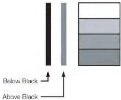
PLUGE patterns vary but generally consist of some combination of black, white, and gray areas against a black background. The example above includes two vertical bars and four shaded boxes.
-
From the Picture Settings menu, select Brightness.
-
Select ▲ or ▼ to adjust the black level so the following happens:
• The darkest black bars disappear into the background.
• The dark gray areas are barely visible.
• The lighter gray areas are clearly visible.
• The white areas are a comfortable level of true white.
• The image contains only black, gray and white (no color).
Contrast and Black Level controls are interactive. A change to one may require a subtle change to the other to achieve the optimum setting.
Setting image color
Color (hue or tint) is the ratio of red to green in the color portion of the image. When Color is decreased, the image appears redder; when it is increased the image appears greener. To adjust the color, use a blue filter when viewing the color bar pattern, as you would for adjusting color saturation.
- From the Pictures Settings menu, select Color.
- Select ▲ or ▼ to adjust the color until the cyan and magenta color bars (on either side of the green bar) appear to be a single shade of blue.
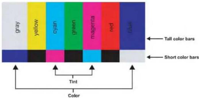
Like the brightness and contrast controls, the color and tint controls are interactive. A change to one may require a subtle change to the other to achieve the optimum setting.
Setting image sharpness
Sharpness is the amount of high-frequency detail in the image.
- From the Pictures Settings menu, select Sharpness.
- On your external test pattern source.
Select a pattern like the one shown below.
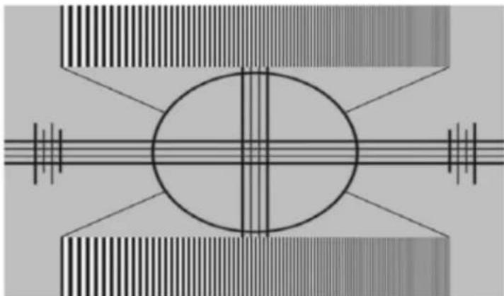
natural_image
Symmetrical abstract diagram with concentric circles and intersecting lines, no text or symbols present- Adjust as needed, looking for white edges around the transitions from black to gray and differently-sized lines in the sweep patterns at the top and bottom. Lower the sharpness setting to eliminate them.
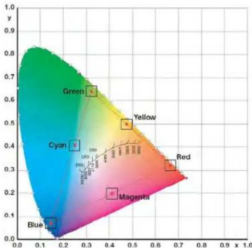
Setting image color temperature
A Color Temperature is an x/y coordinate pair that defines a color's location on the standard CIE chromaticity shown in the graph. CIE stands for Commission Internationale de l'Éclairage International Commission on Illumination, the organization responsible for color measurement and management.
-
From the Pictures Settings menu, select Color Temperature to adjust the color temperature.
-
Sudio1 = 3200K
- Studio2 = 5600K
-
Warm = 6500K
• Normal = 10000K
• Cool = 12000K -
Select a value of from 3200K (Studio1) to 12000K (Cool).
Higher settings produce a bluer picture; lower ones produce a reddish hue to the image.
- To select a custom color temperature, select User.
- Set the Gain and Offset as described below.
scatter
| Category | Value | | -------- | ----- | | Blue | 0.0 | | Magenta | 0.2 | | Cyan | 0.4 | | Yellow | 0.5 | | Green | 0.65 |Enabling or disabling HDR10
HDR10 controls the display's HDR mode enable/disable.
- From the Pictures Settings menu, select HDR10.
- Enable or disable the control.

Caution! If not avoided, the following could result in minor or moderate injury.
• HDR10 support only YCbCr444 format.
Resetting the picture values
Reset all values in the Picture menu.
- From the Pictures Settings menu, select Reset.
All values in the Picture menu are reset.
Sound settings
| Picture | Audio Select | HDMI1 |
| Sound | Volume | 50 |
| OSD | Balance | 0 |
| Setup | ||
| Presets | ||
| LAN Setting | ||
| About | ||
Setting the audio input
- From the Sound menu, select Audio Input.
- Select audio input source:
[DP1], [DP2,][HDMI 1], [HDMI 2], [HDMI 3], [HDMI 4], [OPS-HDMI], [OPS-DP]
Adjusting the volume
The volume can be changed or the sound can be muted only for displays are on.
- From the Sound menu, select Volume.
- Adjust the Volume using the slider bar in the range of 0 to 100.
Adjusting the sound balance
Adjust the volume of the left and right speakers of the selected display device.
- From the Sound menu, select Balance.
- Adjust the Balance using the slider bar in the range of -50 to +50.
OSD settings
| Picture | Language | English |
| Sound | OSD Turn Off | 20sec |
| OSD | OSD Position | C |
| Setup | ||
| Presets | ||
| LAN Setting | ||
| About | ||
Specifying the language
Specify the language for the on-screen display.
- From the OSD Settings menu, select OSD Language.
- Select ▲ or ▼ to choose the on-screen display language.
Valid values: English, French, German, Italian, Russian, Spanish, and Korean
Turning off the on-screen display menus
Specify how long the menus remain on-screen after selecting them.
- From the Basic Settings menu, select OSD Timeout.
Valid values: 5 seconds, 10 seconds, 20 seconds, Off
Determining the on-screen display position
Specify the position displayed on the screen after selecting the menu.
- From the Basic Settings menu, select OSD Position.
Valid values:
- TL: Top Left
- TR: Top Right
C: Center - BL: Bottom Left
- BR: Bottom Right
Setup settings
| Picture | Power Save | On |
| Sound | Power Off Mode | Standby |
| OSD | Interface Select | RS232 |
| Setup | FRC Mode | Free run |
| Presets | CEC Control | Off |
| LAN Setting | OPS/HDMI4 EDID | UHD |
| About | Gamma | 2.2 |
| Auto Source Switch | Off | |
| Low Latency Mode | Off | |
| Factory Reset | ||
Enabling Power Save
- From the Setup menu, select Power Save > On.
After 40 seconds of no signal, the display enters the power-saving mode.
Determining how the display goes into Power Off Mode
- From the Setup menu, select Power Off Mode.
- Determine how you want the display to go into Power Save Mode.
| Power Off Mode | IR RS232 | control | Ethernet control | Crestron control | Power consumption |
| Standby | Yes | Yes | Yes | Yes | Under 5W |
| Sleep | Yes | Yes | No | No | Under 2W |
| Deep Sleep | Yes | No | No | No | Under 0.5W |
When the Power Off Mode is set to sleep, do not enter sleep mode before the Mac address appears in the About menu of the on-screen display. The Mac address display indicates all booting is complete.
Selecting the interface
Determine what type of interface is required.
- From the Setup menu, select the Interface Select.
- Select the control interface.
Valid values: RS232, OPS-RS232, and Off
Setting FRC Mode
Adjusts the amount FRC frequency
-
From the Setup menu, select FRC Mode.
-
Select the FRC Mode value.
When the input vertical frequency 50Hz is applied, the screen is correctly displayed on the high-speed motion screen. Valid values:
• Free Run: Only 60Hz
- Lock: 50Hz/60Hz
Powering the display on or off using a CEC command
Use the CEC Control to power the display on or off using a CEC command.
- From the Setup menu, select CEC Control.
- Enable (On) or disable (Off) the CEC Control.
Setting the OPS/HDMI4 EDID
Set the OPS/HDMI4 EDID.
- From the Setup menu, select OPS/ HDMI 4.
- Select the EDID for the OPS/HDMI4.
Valid values: UHD or FHD.
Determining the gamma curve
- From the Setup menu, select Gamma.
- Set the gamma curve.
Valid values: 2.2 standard or DICOM.
Enabling or disabling the active source
When Auto Source Switch is enabled, the display switches to the currently active source automatically. When the source is removed, the display switches to other active source.
- From the Setup menu, select Auto Source Switch.
- Enable (On) or disable (Off) switching to the current active source automatically.
Enabling or disabling Low Latency Mode
When Low Latency Mode is enabled, the video delay is reduced.
-
From the Setup menu, select Low Latency Mode.
-
Enable (On) or disable (Off) if the video delay is reduced.
Performing a factory reset
Reset all display settings to their factory defaults.
- From the Setup menu, select Factory Reset.
All settings, including image settings are restored to their factory defaults.
Presets
Use the Presets menu to display multiple inputs simultaneously and save them to a preset, which can be quickly recalled.
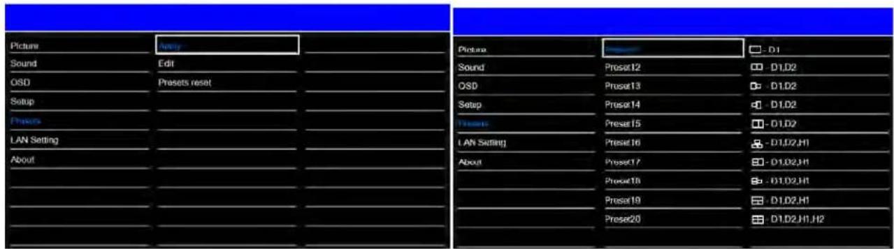
Applying presets
Recall a previously configured preset.
- From the Presets menu, select Apply.
Editing presets
Change the configuration or the source for the preset.
- From the Presets menu, select Edit.
Storing multiple window presets
Store up to 20 different configured multi-window presets
| Number | Window count and input |
| Preset1 One /HDMI1 | |
| Preset2 Dual1 /HDMI1/HDMI2 | |
| Preset3 Dual2 /HDMI1/HDMI2 | |
| Preset4 Dual3 /HDMI1/HDMI2 | |
| Preset5 Dual4 /HDMI1/HDMI2 | |
| Preset6 | Triple1/HDMI1/HDMI2/HDMI3 |
| Preset7 | Triple2/HDMI1/HDMI2/HDMI3 |
| Preset8 | Triple3/HDMI1/HDMI2/HDMI3 |
| Preset9 | Triple4/HDMI1/HDMI2/HDMI3 |
| Preset10 | Quad/HDMI1/HDMI2/HDMI3/HDMI4 |
| Preset11 One /DP1 | |
| Preset12 Dual1 /DP1/DP2 | |
| Preset13 Dual2 /DP1/DP2 | |
| Preset14 Dual3 /DP1/DP2 | |
| Preset15 Dual4 /DP1/DP2 | |
| Preset16 Triple1/DP1/DP2/HDMI1 | |
| Preset17 Triple2/DP1/DP2/HDMI1 | |
| Preset18 Triple3/DP1/DP2/HDMI1 | |
| Preset19 Triple4/DP1/DP2/HDMI1 | |
| Preset20 Quad/DP1/DP2/HDMI1/HDMI2 | |
Resetting presets
Reset the 20 preset settings.
- From the Presets menu, select Presets reset.
Preset Edit
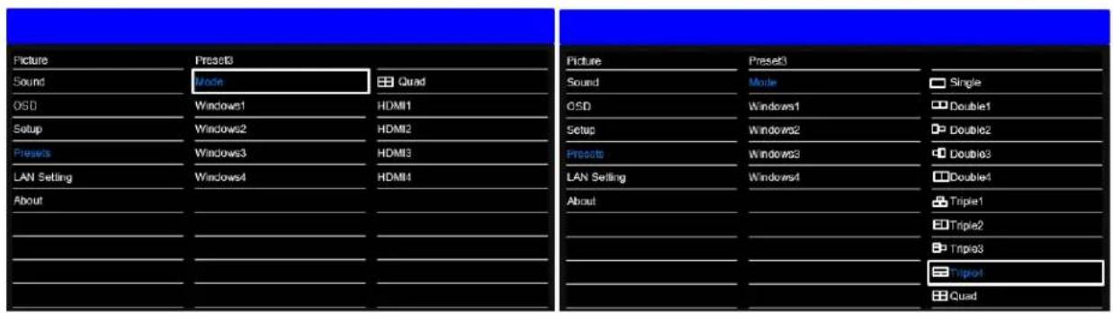
Selecting an input mode
You can select and save several modes to a preset.
- From the Preset menu, select Modes.
- Select an input source.
- Valid values: Single, Dual1, Dual2, Dual3, Dual4, Triple1, Triple2, Triple3, Triple4, and Quad

[One]
[Dual1]
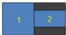
[Dual2]
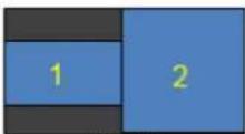
[Dual3]

[Dual4]
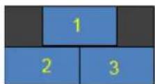
[Triple1]
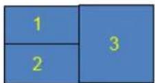
[Triple2]
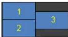
[Triple3]
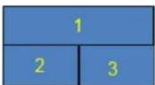
[Triple4]
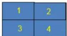
[Quad]
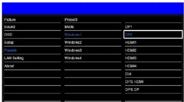
Window1-Window4
To configure which source is in the respective window, select a Source in Window 1-4. Some limitations exist to which sources can be applied in some modes, see below.
| Dual/ Quad | Sub screen | ||||||||
| DP1 | DP2 | HDMI 1 | HDMI 2 | HDMI 3 | HDMI 4 | OPS HDMI | OPS DP | ||
| Main Screen | DP1 | Yes | Yes | Yes | Yes | Yes | Yes | Yes | Yes |
| DP2 | Yes | Yes | Yes | Yes | Yes | Yes | Yes | Yes | |
| HDMI 1 | Yes | Yes | Yes | Yes | Yes | Yes | Yes | Yes | |
| HDMI 2 | Yes | Yes | Yes | Yes | Yes | Yes | Yes | Yes | |
| HDMI 3 | Yes | Yes | Yes | Yes | Yes | Yes | Yes | Yes | |
| HDMI 4 | Yes | Yes | Yes | Yes | Yes | Yes | No | No | |
| OPS-HDMI | Yes | Yes | Yes | Yes | Yes | No | Yes | No | |
| OPS-DP | Yes | Yes | Yes | Yes | Yes | No | No | Yes | |
Viewing status information
| Picture | Model: SUHD863-L | MAC : 2D:3F:45:1C:5A:98 |
| Sound | Version : 1.0.0.0 - 1 | S/N : SUHD86U330001 |
| OSD | Window1 | HDMI1 |
| Setup | Resolution | 1920x1080@60Hz |
| Presets | Window2 | HDMI2 |
| LAN Setting | Resolution | 1920x1080@60Hz |
| About | Window3 | HDMI3 |
| Resolution | 1920x1080@60Hz | |
| Window4 | HDMI4 | |
| Resolution | 1920x1080@60Hz |
The read-only About menu provides the following status information about the display:
• Resolution and refresh rate of the active source
• Currently-installed firmware version
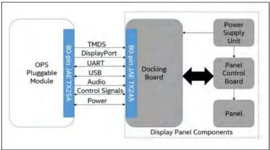
Open Plugable Specification (OPS)
This section describes the electrical and mechanical specifications of the Open Pluggable Specification (OPS), which enables a standard and easier integration of a pluggable module into the display panel.
Throughout this section the 80pin JAE TX24A/TX25A series connector is referred to as the JAE connector. Dimensions shown in all figures are in unit mm.
flowchart
graph LR
    A["OPS Pluggable Module"] --> B["80-pin JAE TX25A"]
    B --> C["TMDS"]
    B --> D["DisplayPort"]
    B --> E["UART"]
    B --> F["USB"]
    B --> G["Audio"]
    B --> H["Control Signals"]
    B --> I["Power"]
    B --> J["Docking Board"]
    J --> K["Power Supply Unit"]
    J --> L["Panel Control Board"]
    L --> M["Panel"]
    J <--> K
    J <--> L
    style A fill:#4a6fa5,stroke:#333
    style J fill:#99ccff,stroke:#333
The OPS involves the integration concept of a pluggable module into the display panel through a single and standard interfacing based on the 80 pin JAE plug and receptacle connectors.

natural_image
Two black plastic electronic components with mounting brackets, shown from different angles (no text or symbols visible)The connector used for the Pluggable Module and the docking board interconnect is based on the JAE TX24A/TX25A family of plug and receptacle connectors. The JAE connector pins are capable of supporting up to a maximum current of 1A. The 80-pin right angle blind mate plug connector (P/N: TX25A-80P-LT-H1E) and its receptacle (P/N: TX24A-80R-LT-H1E) provide interfacing for the following features.
• Power: DC IN +12V\~+19V @ 8A maximum
• Display Interface: DVI-D/TMDS† and DisplayPort
• Audio: Left and Right Channel
• USB: 3xUSB 2.0 (when USB3.0 is not used) or 2xUSB 2.0 and 1xUSB 3.0
• UART: Serial communication (Tx and Rx only)
• The connector series image is for reference only.
- Control Signals: Pluggable Module Power Status, Power ON using display panel, Pluggable Board Detect, Consumer Electronics Control (CEC), and System Fan Control.
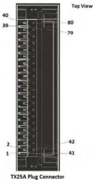
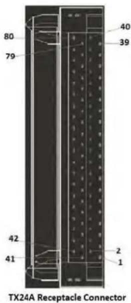
Left: Plug connector (P/N: TX25A-80P-LT-H1E).
Right: Receptacle connector (P/N: TX24A-80R-LT-H1E).

Caution! If not avoided, the following could result in minor or moderate injury.
• Always use screws to install OPS.
- Do not swap OPS modules while the display is powered on.
• This display supports OPS power consumption up to 60W.
Supported timings
| Signal Type | Format | Hres | Vres | Frame rate (Hz) | Sampling Bit-Depth | |
| HDMI | 640x480 | 640 | 480 | 60 | RGB/4:4:4/4:2:2 | 8/10/12bpc |
| 800x600 | 800 | 600 | 50,60 | RGB/4:4:4/4:2:2 | 8/10/12bpc | |
| 1024x768 | 1024 | 768 | 50,60 | RGB/4:4:4/4:2:2 | 8/10/12bpc | |
| 1280x720 | 1280 | 720 | 50,60 | RGB/4:4:4/4:2:2 | 8/10/12bpc | |
| 1280x800 | 1280 | 800 | 50,60 | RGB/4:4:4/4:2:2 | 8/10/12bpc | |
| 1280x1024 | 1280 | 1024 | 50,60 | RGB/4:4:4/4:2:2 | 8/10/12bpc | |
| 1600x900 | 1600 | 900 | 50,60 | RGB/4:4:4/4:2:2 | 8/10/12bpc | |
| 1920x1080 | 1920 | 1080 | 50,60 | RGB/4:4:4/4:2:2 | 8/10/12bpc | |
| 3840x2160 | 3840 | 2160 | 30,50,60 | RGB/4:4:4/4:2:2 | 8/10/12bpc | |
| DP | 640x480 | 640 | 480 | 60 | RGB/4:4:4 | 8/10/12bpc |
| 800x600 | 800 | 600 | 50,60 | RGB/4:4:4 | 8/10/12bpc | |
| 1024x768 | 1024 | 768 | 50,60 | RGB/4:4:4 | 8/10/12bpc | |
| 1280x720 | 1280 | 720 | 50,60 | RGB/4:4:4 | 8/10/12bpc | |
| 1280x800 | 1280 | 800 | 50,60 | RGB/4:4:4 | 8/10/12bpc | |
| 1280x1024 | 1280 | 1024 | 50,60 | RGB/4:4:4 | 8/10/12bpc | |
| 1600x900 | 1600 | 900 | 50,60 | RGB/4:4:4 | 8/10/12bpc | |
| 1920x1080 | 1920 | 1080 | 50,60 | RGB/4:4:4 | 8/10/12bpc | |
| 3840x2160 | 3840 | 2160 | 30,50,60 | RGB/4:4:4 | 8/10/12bpc | |
| OPS HDMI, OPS DP | 640x480 | 640 | 480 | 60 | RGB/4:4:4/4:2:2 | 8/10/12bpc |
| 800x600 | 800 | 600 | 50,60 | RGB/4:4:4/4:2:2 | 8/10/12bpc | |
| 1024x768 | 1024 | 768 | 50,60 | RGB/4:4:4/4:2:2 | 8/10/12bpc | |
| 1280x720 | 1280 | 720 | 50,60 | RGB/4:4:4/4:2:2 | 8/10/12bpc | |
| 1280x800 | 1280 | 800 | 50,60 | RGB/4:4:4/4:2:2 | 8/10/12bpc | |
| 1280x1024 | 1280 | 1024 | 50,60 | RGB/4:4:4/4:2:2 | 8/10/12bpc | |
| 1600x900 | 1600 | 900 | 50,60 | RGB/4:4:4/4:2:2 | 8/10/12bpc | |
| 1920x1080 | 1920 | 1080 | 50,60 | RGB/4:4:4/4:2:2 | 8/10/12bpc | |
| 3840x2160 | 3840 | 2160 | 30,50,60 | RGB/4:4:4/4:2:2 | 8/10/12bpc | |
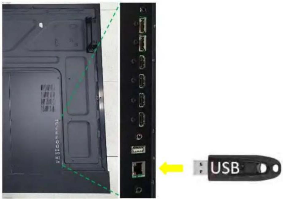
Updating the Scaler firmware using USB
Follow these steps to update the Scaler firmware using a USB.

Regardless of the software version, the filename must always be Secure_Series_II.bin to upload correctly.
- Plug in a USB memory to the service terminal.
The firmware is stored on the USB and the filename of firmware must be Secure_Series_II.bin.
- Enter the Factory menu.
To enter the Factory menu using the remote control:

flowchart
graph LR
    A["SOURCE"] --> B["UP"]
    B --> C["RIGHT"]
    C --> D["DOWN"]
    D --> E["LEFT"]
- Select Software Update (USB) and select SEL on the remote control
To enter the Factory menu. disable Multi-Window mode.
4. Select USB Update.
• If the Connected message appears, select USB Update.
The firmware is automatically updated. The panel goes into Standby mode after a successful firmware update (approximately 30 seconds).
a. Reset the main power switch to turn the panel on.
b. When the firmware update is complete, perform an Initial Setting in the Factory menu.
c. When the Initial Setting is complete, power off the panel using the rocker-switch.
d. Wait at least 10 seconds and power the panel on.
- In case the USB storage device is not compatible, a Can't Detect USB message appears.
Network guide
Connecting the monitor and the computer using the network, remote control, and status monitoring of the monitor can be performed by web browser.
Setting the connection
- To use a static IP address, select Disable under DHCP.
| Picture | DHCP | Disable |
| Sound | IP Address | 192.168.10.10 |
| OSD | Subnet Mask | 255.255.255.0 |
| Setup | Gate Way | 192.168.10.1 |
| Presets | DNS | 168.126.63.1 |
| LAN Setting | LAN Setting Reset | |
| About | ||
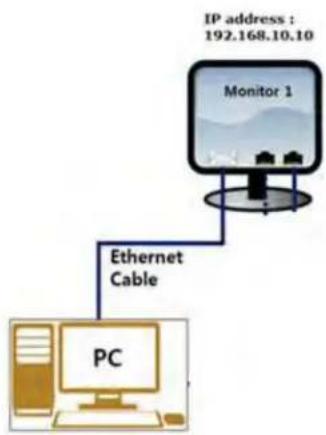
flowchart
graph TD
    A["IP address : 192.168.10.10"] --> B["Monitor 1"]
    B --> C["Ethernet Cable"]
    C --> D["PC"]
The default static IP address is 192.168.10.10
- Select DHCP Enable to use a dynamic IP address
• If there is router, the IP address starts with 192.168.
• If there is no router, the IP address starts with 169.254.
| Picture | DHCP | Enable |
| Sound | IP Address | 192.168.1.3 |
| OSD | Subnet Mask | 255.255.255.0 |
| Setup | Gate Way | 192.168.10.1 |
| Presets | DNS | 168.126.63.1 |
| LAN Setting | LAN Setting Reset | |
| About | ||
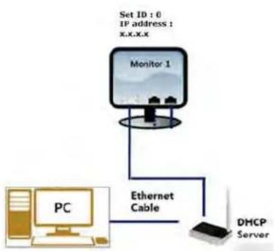
flowchart
graph TD
    A["PC"] -->|Ethernet Cable| B["Monitor 1"]
    B --> C["DHCP Server"]
    D["Set ID : 0\nIP address : X,X,X,X"] --> B
PC Setting
- Go to Local Network Setting - Internet protocol version 4(TCP/IPv4).
- If DHCP disable on the on-screen display, From the General tab set the following:
• IP address: 192.168.10.50
The IP address must be a different address than the display.
- Subnet Mask: 255.255.255.0
- If DHCP is enabled, select Obtain an IP address automatically.
- Select OK.
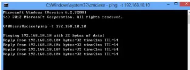
Completing a ping test
The ping test checks the Ethernet connection.
- Select Windows + R.
- Enter cmd.
- Select OK
- Enter ping -t 192.168.10.10.
Replace the IP address with the address of display panel.
A response similar to below indicates success:
A response similar to below indicates a failure
![C:\Windows\system32\cmd.exe - ping -t 192.168.10.10 Microsoft Windows [Version 6.2.7200] (c) 2012 Microsoft Corporation. All rights reserved. C:\Windows\Wcesoo> C:\Windows\Wcesoo>ping -t 192.168.10.10 Pinging 192.168.10.10 with 32 bytes of data: Reply from 192.168.1.9%: Destination host unreachable. Reply from 192.168.1.9%: Destination host unreachable. Reply from 192.168.1.9%: Destination host unreachable.](/content/2026/05/1064581/images/9c32f623d4527637846c3acaa0d0b7b3399f8e496b3550dd9ac1794daaab6e8d.jpg)
Connecting a web server
To connect to the built-in web server open a web browser (for example, Internet Explorer or Chrome) and follow the instructions below.
- In a web browser, go to the address of the display panel.
The web page provides all the menu controls on the on-screen display.
- To set a value, select Apply.
- To display the current value, select Read.
Upgrading the Ethernet or Scaler firmware
-
To upgrade the Ethernet or Scaler firmware, go to the General settings page.
-
Ethernet firmware update time: approximately 5 minutes
- Scaler firmware update time: approximately 8 minutes

Caution! If not avoided, the following could result in minor or moderate injury.
- Do not disconnect LAN cable or power off during F/W update
- Wait until upgrade complete message show
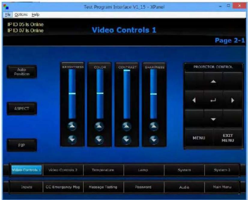
Connecting to the Crestron-X-panel program
To connect to Crestron by X-Panel program, use the X-Panel program. Follow the instructions below.
- Execute the X-Panel program.
- Select options > Settings.
- In the Gateway Settings dialog, set the IP address 192.168.10.10 (Monitor IP) and Port 41794.
- Control the monitor settings, for example, the Picture setting and remote control.
Connecting to the Crestron-Roomview program
To connect to Crestron by Roomview program, Use the Roomview program. Follow the instructions below.
- Execute the Roomview program.
- Add New Room to control the monitor or load Roomview database file.
- Select Edit > Rooms > New Room.
-
Set the following:
-
Set Name
-
Location
• IP address 192.168.10.10 (Monitor IP)
IP ID/Port 41794 -
Select Browser > Open and select the Load Roomview database file.
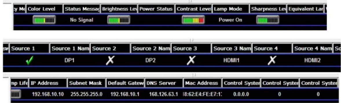
Controlling monitor settings
You can control monitor settings, such as adding various attributes.
Maintenance and troubleshooting
Maintenance
Under normal operating conditions, routine maintenance is not required. No user-serviceable or replaceable parts exist. Unless you are a qualified, factory-trained technician, do not attempt to repair or replace any system component or the product warranty maybe voided.
Troubleshooting
The table below provides some general guidelines for troubleshooting problems you may encounter with your display. If the suggested solutions fail to resolve the problem or if you encounter an issue not described here, contact your dealer.
| Symptom | Possible causes | Solution |
| The display does not turn on. | The display is not plugged in or the AC outlet is not active.The main power switch is off.The remote control batteries have run out. | Ensure the display is plugged in and the AC outlet is active.Set the main power switch (see Display-at-a-glance on page 13) to the on position.Replace the batteries. |
| The display is on and menus appear but there is no picture. | Incorrect source selection.Source component is not turned on.Source component is connected incorrectly or not at all. | Select the correct source.Turn on the source component.Check connections from the source component to the display.Reboot or restart the source. |
| The remote control does not work. | The remote control batteries have run out. | Replace the batteries. |
| The display is jittery or unstable. | Poor-quality or improperly connected source.The horizontal or vertical scan frequency of the input signal may be out of range for the display. | Make sure the source is properly connected and of adequate quality for detection.Correct at the source.Use a different certified cable. |
| Image is too bright and/or lacks definition in the bright areas of the image. | Contrast is set too high. | Decrease the contrast setting. |
| Image appears washed out and/or dark areas appear too bright. | Black level is set too high. | Decrease the black level setting. |
| Image is too dark. | Black level and/or brightness are set too low. | Increase the black level and/or brightness settings. |
| Images from an HDMI source do not display. | The resolution and frequency of the video card in the computer are not compatible with the display.HDMI cable from source to display is either defective or too long. | Select a compatible resolution and vertical frequency (see Supported timings on page 47).Try a known good and/or shorter HDMI cable. |
| Computer images do not display correctly. | The resolution and frequency of the video card in the computer are not compatible with the display.The Clock and Phase settings need adjustment. | Select a compatible resolution and vertical frequency (see Supported timings on page 47). |