FHD551-X - Monitor Christie - Free user manual and instructions
Find the device manual for free FHD551-X Christie in PDF.

User questions about FHD551-X Christie
0 question about this device. Answer the ones you know or ask your own.
Ask a new question about this device
Download the instructions for your Monitor in PDF format for free! Find your manual FHD551-X - Christie and take your electronic device back in hand. On this page are published all the documents necessary for the use of your device. FHD551-X by Christie.
USER MANUAL FHD551-X Christie
All brand names and product names are trademarks, registered trademarks or trade names of their respective holders.
REGULATORY
The product has been tested and found to comply with the limits for a Class A digital device, pursuant to Part 15 of the FCC Rules. These limits are designed to provide reasonable protection against harmful interference when the product is operated in a commercial environment. The product generates, uses, and can radiate radio frequency energy and, if not installed and used in accordance with the instruction manual, may cause harmful interference to radio communications. Operation of the product in a residential area is likely to cause harmful interference in which case the user will be required to correct the interference at the user's own expense.
This Class A digital apparatus complies with Canadian ICES-003.
Every effort has been made to ensure accuracy, however in some cases changes in the products or availability could occur which may not be reflected in this document. Christie reserves the right to make changes to specifications at any time without notice. Performance specifications are typical, but may vary depending on conditions beyond Christie's control such as maintenance of the product in proper working conditions. Performance specifications are based on information available at the time of printing. Christie makes no warranty of any kind with regard to this material, including, but not limited to, implied warranties of fitness for a particular purpose. Christie will not be liable for errors contained herein or for incidental or consequential damages in connection with the performance or use of this material.

The product is designed and manufactured with high-quality materials and components that can be recycled and reused. This symbol means that electrical and electronic equipment, at their end-of-life, should be disposed of separately from regular waste. Please dispose of the product appropriately and according to local regulations. In the European Union, there are separate collection systems for used
electrical and electronic products. Please help us to conserve the environment we live in!
GENERAL WARRANTY STATEMENTS
For complete information about Christie's limited warranty, please contact your Christie dealer. In addition to the other limitations that may be specified in Christie's limited warranty, the warranty does not cover:
a. Damage occurring during shipment, in either direction.
b. Damage caused by misuse, improper power source, accident, fire, flood, lightning, earthquake or other natural disaster.
c. Damage caused by improper installation/alignment, or by product modification, if by other than a Christie authorized repair service provider.
d. Problems caused by combination of the equipment with non-Christie equipment, such as distribution systems, cameras, video tape recorders, etc., or use of the equipment with any non-Christie interface device.
e. Failure due to normal wear and tear.
f. Warranty does not cover image retention.
PREVENTATIVE MAINTENANCE
Preventative maintenance is an important part of the continued and proper operation of your product. Please see the Service Manual for specific maintenance items as they relate to your product. Failure to perform maintenance as required, and in accordance with the maintenance schedule specified by Christie, will void the warranty.
Addendum
The CD included with this printed manual contains an electronic copy in English. Please read all instructions before using or servicing this product.
1.1 Safety Warnings and Guidelines .... 1-1
1.2 LCD Flat Panel Overview 1-2
1.3 Standard Components.... 1-2
1.4 Optional Hardware Components 1-2
1.5 Other Available Resources 1-3
1.5.1 Indicator Lights, Control and Connections.... 1-3
1.5.2 Connection Panel 1-4
1.5.3 Power Connection Panel....1-6
2: Package Handling
2.1 Unpacking....2-1
2.2 Handling and Care 2-2
2.3 Cleaning....2-2
3: Installation Guidelines
3.1 Power 3-1
3.2 Remote Requirements....3-1
3.3 Tiling 3-2
3.4 Cabling....3-3
3.4.1 RS232 Routing....3-3
3.4.2 DVI/VGA Loop Through 3-4
DVI Routing 3-4
VGA Routing 3-4
3.5 Cable Tether Kit (for FHD551-X/XG only)....3-5
3.6 Cooling Requirements 3-5
3.7 Runtime 3-6
3.8 Application Software....3-6
4: Operation
4.1 LCD Panel Setup 4-1
4.1.1 Video Source Connections....4-1
4.2 Enabling Power....4-2
4.2.1 Connect the Power Cable....4-2
4.2.2 Enable Power 4-2
4.2.3 Select Input Source 4-2
4.2.4 Disable Power 4-2
4.3 On-screen Display (OSD)....4-3
4.3.1 OSD Remote Control 4-3
4.3.2 OSD Menu Overview 4-4
4.3.3 Image Settings Menu 4-4
4.3.4 Image Settings—Color Temp and Gamma....4-5
4.3.5 Display Settings Menu....4-6
4.3.6 Audio Settings Menu 4-7
4.3.7 Basic Settings Menu 4-8
4.3.8 Advanced Settings Menu 4-9
4.3.9 Advanced Settings Menu continued ....4-10
4.3.10 System Status Menu....4-11 User ADC Calibration ....4-11
4.4 Video Wall Matrix Setup....4-12
4.4.1 Example: 3x3 Screen Matrix (9 displays)....4-12
4.4.2 Video Wall Parameters ...... 4-13
4.4.3 Setup Video Wall Parameter on OSD Menu 4-13
4.4.4 Setup Video Wall Parameters using RS232....4-14
4.4.5 Setup Video Wall Parameters using Video Wall Toolbox 4-14
4.5 RS232 Control 4-14
4.6 Video Wall Toolbox 4-15
4.6.1 Automatic Video Wall Setup....4-15 Example of a 3x3 Screen Matrix with a Single Source ....4-15
4.6.2 Manual Video Wall Setup....4-16 Example of a 3x5 Video Wall with 2 DVI Sources....4-16
4.7 Frame Compensation 4-17
5: Troubleshooting
5.1 No Image....5-1
5.2 Screen Color Abnormal 5-1
5.3 Flickering Screen 5-1
5.4 Picture is Dark 5-1
5.5 Picture Ghosting 5-1
5.6 Picture Size is Incorrect 5-1
5.7 White Color is Incorrect....5-2
5.8 Screen Image Not Centered 5-2
5.9 Remote Control Not Functioning 5-2
6: Specifications
6.1 LCD Panel....6-1
6.2 Physical Dimensions....6-1
6.3 Graphic....6-2
6.4 Scan Rate 6-2
6.5 Performance....6-2
6.6 Power Source 6-2
6.7 LCD Quality Inspection....6-3
6.7.1 Pixels....6-3
6.7.2 Uniformity....6-3
6.8 Environment....6-3
6.9 DDC 6-3
6.10 Function 6-4
6.11 RS232 1:N Control ....6-4
7: Timing Table
A: RS232 Command Format
A.1 RS232 Command Format ...... A-1
A.2 Serial Port Setting....A-1
A.3 Configuring a 2x2 Video Wall (DVI Input Source)....A-8
A.4 Additional Examples ......A-9
B: Mechanical Drawings
B.1 FHD551-X ...... B-3
B.2 FHD551-XG B-4
B.3 FHD461-X B-5
1 Product Overview
Every effort has been made to make sure the information in this document is accurate and reliable; however, due to constant research, the information in this document is subject to change without notice. Christie assumes no responsibility for omissions or inaccuracies.
1.1 Safety Warnings and Guidelines
WARNING
Failure to comply with the following may result in death or serious injury:
- This product is designed and manufactured to operate within defined design limits and misuse may result in electric shock or fire.
- Never push any object into the slot on the monitor cabinet. Do not place any objects on the top of the product. It could short circuit parts causing a fire or electric shock. Never spill liquids on the monitor.
- To avoid the risk of electric shock or component damage, disable power before connecting other components to the LCD panel.
CAUTION
Failure to comply with the following could result in minor or moderate injury:
- Do not place the monitor on an unstable cart, stand, or table. If the monitor falls, it can injure a person and cause serious damage to the appliance. Use only a cart or stand recommended by the manufacturer or sold with the monitor.
- Keep the monitor away from moisture. Do not expose this product to rain or moisture. If water penetrates the product, unplug the power cord and contact your dealer. Continuous use in this case may result in fire or electric shock.
- Do not use the product if any abnormality occurs. If any smoke or odor becomes apparent, unplug the power cord and contact your dealer immediately. Do not try to repair the product yourself.
- Avoid using dropped or damaged appliances. If the product is dropped and the housing is damaged, the internal components may function abnormally. Unplug the power cord immediately and contact your dealer for repair. Continued use of the product may cause fire or electric shock.
- Do not install the product in an area with heavy dust or high humidity. Operating the product in these environments may cause fire or electric shock.
1.2 LCD Flat Panel Overview
Christie FHD551-X/XG and Christie FHD461-X LCD flat panels deliver full HD resolution (1920 x 1080) suitable for a variety of indoor environments. They feature a slim chassis design and use low-power components making them energy-efficient. Multiple video streams can be arranged on a single monitor to reduce installation power requirements.
Standard monitor display parameters can be adjusted with user-friendly, on-screen menus and side panel controls.
Christie FHD551-XG flat panels use an optically bonded Corning® Gorilla® Glass option making them scratch and damage resistant; ideal for touchscreen interactivity or high-traffic areas.
1.3 Standard Components
NOTICE: Always use the accessories recommended by the manufacturer to guarantee compatibility.
LCD Panel Components
| Model Part Number Description | ||
| FHD551-X 135-0011 | 02-01 • 2m Ethernet Cable (RS-485) | |
| FHD551-XG 135-002 | 103-01 | • 3m RS232 Cable• DVI Cable• IR Extender Cable• Cable Tether Kit• IR Remote Control (includes 2, AAA batteries)• LCD Panel FHD User Manual(with CD containing translated languages of User and Service Manuals) |
| FHD461-X 135-0031 | 04-01 | |
Power Cords
| Part Number Description | |
| 108-383105-01 | Power Cord NA |
| 108-390103-01 | Power Cord EU |
| 108-388100-01 | Power Cord UK |
| 108-376107-01 | Power Cord JP |
| 108-375106-01 | Power Cord CN |
| 108-392105-01 | Power Cord AU |
| 108-498102-01 | Power Cord INDIA |
1.4 Optional Hardware Components
| Part Number Description |
| 135-101103-01 LCD Mount 40-65” ML10 (Landscape) |
| 135-104106-01 LCD Mount 40-65” MP10 (Portrait) |
| 135-102104-01 LCD Spacer Kit 55” ML10 |
| 135-107109-01 LCD Spacer Kit 55” MP10 |
| 135-105107-01 LCD Frame F100 |
| 135-106108-01 LCD Pedestal P100 |
1.5 Other Available Resources
Access the company website www.christiedigital.com to view the listed resources.
- ML10/MP10 LCD Video Wall Mount Instruction Sheet (P/N: 020-100726-xx)
- ML10/MP10 46" and 55" Spacer Kit Instruction Sheet (P/N: 020-100728-xx)
• P100 Pedestal and F100 Frame Installation Manual (P/N: 020-100734-xx)
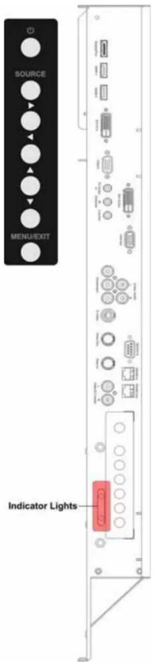
1.5.1 Indicator Lights, Control and Connections
On-screen Display (OSD) Keypad Function List
| Key Description | |
| Power Power | switch; Power ON/OFF |
| Source Source | selection; Activate selection |
| ▶ | Menu right/Increase value |
| ◀ | Menu left/Decrease value |
| ▲ | Menu UP |
| ▼ | Menu DOWN |
| Menu/Exit OSD control menu button | |
LED Indicator Lights
| Indicator Description | |
| Green Normal operation | |
| Blinking orange No signal | |
| Orange Power saving | |
| OFF | Power disabled |
| OFF | AC disabled |
Shown: FHD551-X, FHD551-XG
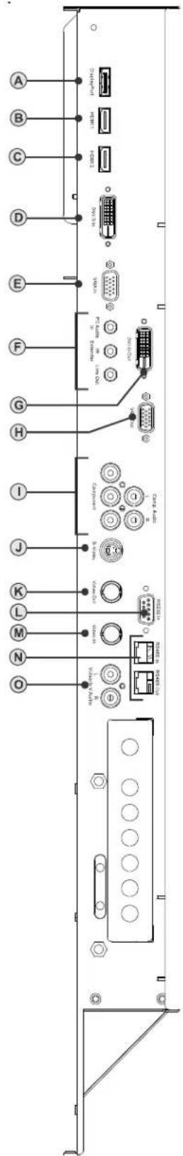
1.5.2 Connection Panel
Shown: FHD551-X, FHD551-XG
| Name Connector | ||
| A Display Port x1 Display Port | ||
| B/C HDMI input x2 HDMI | ||
| D DVI-D input x1 D-sub 24 pin | ||
| E VGA (PC) input x1 D-sub 15 pin | ||
| F Line Out x1 Mini jack | ||
| F IR Extender x1 Mini jack | ||
| F PC Audio IN x1 Mini jack | ||
| G DVI-D output x1 D-Sub 24 pin | ||
| H VGA (PC) output x1 D-Sub 15 pin | ||
| I | Y-Pb-Pr (Y-Cb-Cr) input x1 | RCA G/B/R |
| I | Audio for Component input x1 | RCA L/R |
| J | S-video input x1 | Mini Din 4 pin |
| K Video input/output BNC | ||
| L RS232 input x1 D-Sub 9 pin | ||
| M | Video input/output | BNC |
| N RS485 Input x1RS485 Output x1 | RJ45 | |
| O Audio for S-video/Video input x1 RCA L/R | ||
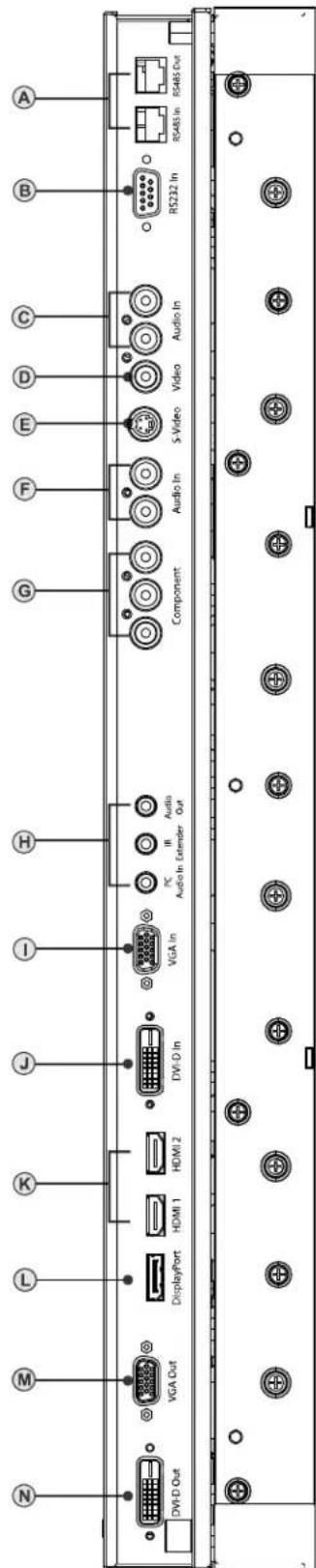
Shown: FHD461-X
| Name Connector | ||
| A RS485 Input x1RS485 Output x1 | RJ45 | |
| B RS232 input x1 D-Sub 9 pin | ||
| C Audio for S-video/Video input x1 RCA L/R | ||
| D Video input/output RCA | ||
| E S-video input x1 Mini Din 4 pin | ||
| F Audio for Component input x1 RCA L/R | ||
| G Y-Pb-Pr (Y-Cb-Cr) input x1 RCA G/B/R | ||
| H | Line Out x1IR Extender x1PC Audio IN x1 | Mini jack |
| I VGA(PC) input x1 D-sub 15 pin | ||
| J DVI-D input x1 D-sub 24 pin | ||
| K HDMI input x2 HDMI | ||
| L Display Port x1 Display Port | ||
| M | VGA (PC) output x1 | D-Sub 15 pin |
| N DVI-D output x1 D-Sub 24 pin | ||
1.5.3 Power Connection Panel
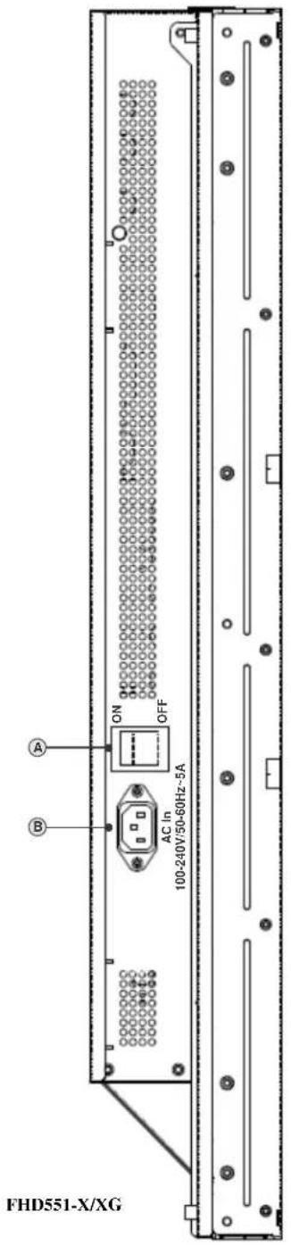
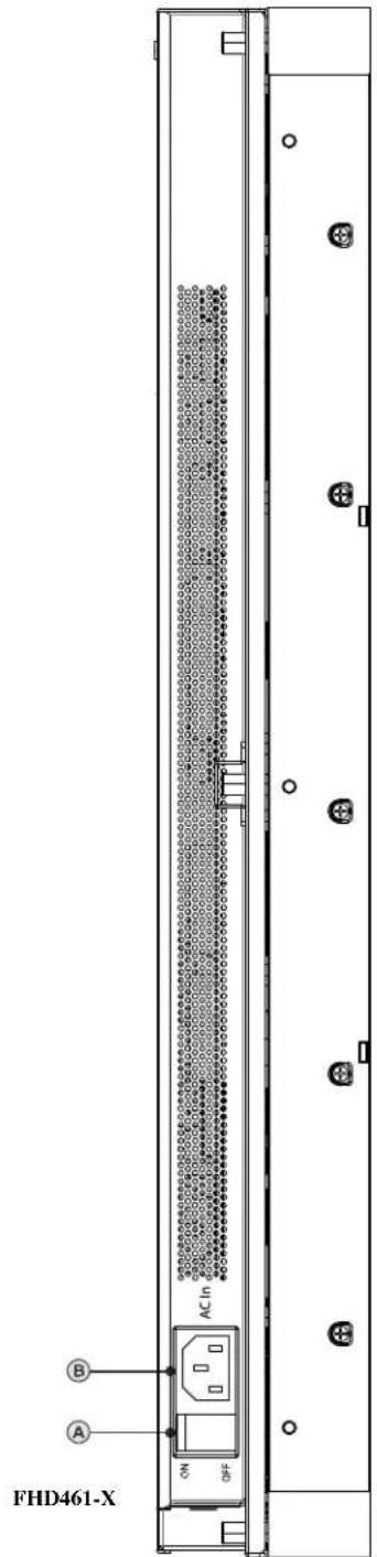
| Name Connector | ||
| A Power | Switch Rocker switch | |
| B Power | Inlet IEC C14 | |
2 Package Handling
WARNING
Failure to comply with the following could result in death or serious injury:
- Do not drop the panel (even a short distance), or apply pressure to the sides of the bezel. The small size of the bezel, which enables minimal image-to-image gaps, means there is reduced protection of the LCD glass and components. Dropping the panel or applying unnecessary force to the sides of the bezel will result in permanent damage.
• To avoid serious injury and/or serious damage to the LCD panel, moving the panel requires at least two people. Hold the white handles on the shipping package when moving/shipping. Failure to properly handle the package may result in serious injury.
- Extreme care must be taken when pushing the mounted display into its locked position. Always handle the display on the opposing corners of the frame to avoid direct contact with the LCD glass.
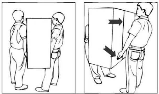
natural_image
Two-panel line drawing showing a person holding a rectangular object, with arrows indicating movement or force direction (no text or symbols)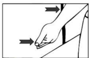
natural_image
Illustration of a hand pressing down on a surface with directional arrows indicating motion (no text or symbols)
2.1 Unpacking
Each LCD panel is packed inside a box carton. To protect the panel during transportation, additional packing material has been placed within the carton. Before unpacking, prepare a stable, level and clean surface near a wall outlet for your LCD panel. Set the box in an upright position and pull out the white carton locks. Lift up the top cover carton. Remove the ESD bag before removing the display from the bottom tray carton.
2.2 Handling and Care
⚠ CAUTION Make sure the power connector and any other cables are unplugged before moving the product. Failure to comply could result in minor or moderate injury.
To avoid damaging your LCD panel, follow these guidelines when handling or moving the panel:
- Hold and support the LCD panel at each side and keep at an even height above the ground.
- Do not twist or bend the panel.
• Always use the handles on the back of the LCD panel. Do not hold onto the frame when transporting. - Two people are required when moving or raising the LCD panel. Use both hands, one positioned on the top handle and the other on the bottom handle.
- Use a cart to move several panels at one time.
- When the panel is sitting on a surface, do not tilt it more than 10^ to avoid damaging the screen.

2.3 Cleaning
NOTICE: Unplug the power cord before cleaning the LCD panel. Do not use a liquid, spray cleaners, or any abrasive cleaners to clean the LCD panel. Failure to comply may result in equipment damage.
Use a cloth dampened with water or methyl alcohol to clean the screen surface. It is recommended you keep the protective plastic sheet shipped with the panel to replace it each time the panels are packed and shipped.
3 Installation Guidelines
3.1 Power
WARNING
Failure to comply with the following could result in death or serious injury:
- Electrical Shock Hazard! Always power down and disconnect/disengage all power sources to the panel(s) before servicing or cleaning. Read and understand all product safety labels before installing/operating this product.
- Do not attempt to repair or service the product yourself. Opening or removing the back cover may expose you to high voltages, the risk of electric shock and other hazards. If repair is required, contact your dealer and refer all servicing to qualified service personnel.
3.2 Remote Requirements
NOTE: Due to the length limitations of the IR cables, if constructing arrays larger than 4x4, it is advised that you configure each monitor before assembling it into the video wall. For example, in a 3x3 array, the IR cable for the center monitor is long enough to reach the top and bottom of the video wall, but does not reach the sides.
Connect the supplied IR extender cable to each monitor to access OSD features using the IR remote. One remote may be used to simultaneously access the OSD on all monitors providing there is line of sight to each IR receiver. For independent control of each monitor, aim the remote at the receiver connected to the monitor. When working with large arrays it is more practical to control the LCD monitors through RS232.
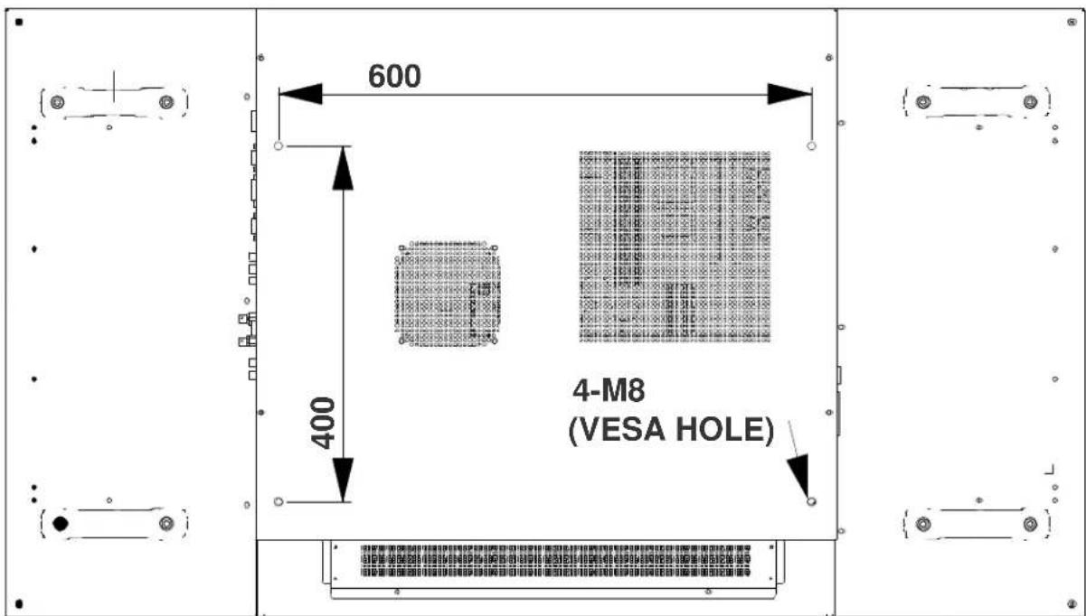
3.3 Tiling
⚠ CAUTION Before installing, make sure the wall/structure is strong enough to withstand the weight of the display and mount. Failure to comply could result in minor or moderate injury.
NOTICE: To avoid damaging the LCD panels, do not stack on top of each other. Allow a minimum 1 mm (0.04") clearance between panels.
To tile the LCD panels they must be mounted to an external mounting structure. The illustration below points out the 4 mounting positions on the back of the LCD panel. For details on how to correctly mount the panels to the wall mount, see ML10/MP10 Video Wall Mount Instruction Sheet (P/N: 020-100726-xx).
-
Carefully place the LCD Panel on a flat surface with the display side facing down. For details on how to properly handle the LCD panel, see Section 2 Package Handling.
-
Remove the 4 M8/15 screws from the back of the LCD monitor.
-
Align the wall mount brackets with the mounting holes on the back of the panel and attach it using the screws removed in step 2.
NOTE: Using long screws will damage the monitor. Use maximum 15mm (0.59") screw lengths.
3.4 Cabling
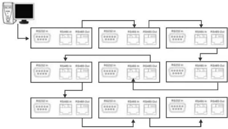
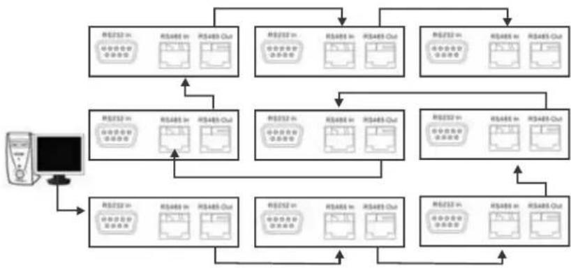
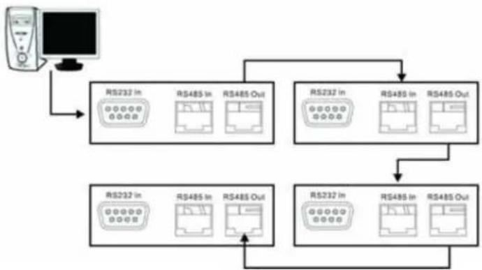
3.4.1 RS232 Routing
The number of connecting devices for RS232 is a maximum of 25 connecting from top-left or bottom-left.
Example 1: 3x3 Screen Matrix connecting from top-left
flowchart
graph TD
    A["Computer"] --> B["RSD232 in"]
    A --> C["RSD485 in"]
    A --> D["RSD485 Out"]
    B --> E["RSD232 in"]
    B --> F["RSD485 in"]
    B --> G["RSD485 Out"]
    C --> H["RSD232 in"]
    C --> I["RSD485 in"]
    C --> J["RSD485 Out"]
    D --> K["RSD232 in"]
    D --> L["RSD485 in"]
    D --> M["RSD485 Out"]
    E --> N["RSD232 in"]
    E --> O["RSD485 in"]
    E --> P["RSD485 Out"]
    F --> Q["RSD232 in"]
    F --> R["RSD485 in"]
    F --> S["RSD485 Out"]
    G --> T["RSD232 in"]
    G --> U["RSD485 in"]
    G --> V["RSD485 Out"]
    H --> W["RSD232 in"]
    H --> X["RSD485 in"]
    H --> Y["RSD485 Out"]
    I --> Z["RSD232 in"]
    I --> AA["RSD485 in"]
    I --> AB["RSD485 Out"]
    J --> AC["RSD232 in"]
    J --> AD["RSD485 in"]
    J --> AE["RSD485 Out"]
    K --> AF["RSD232 in"]
    K --> AG["RSD485 in"]
    K --> AH["RSD485 Out"]
    L --> AI["RSD232 in"]
    L --> AJ["RSD485 in"]
    L --> AK["RSD485 Out"]
    M --> AL["RSD232 in"]
    M --> AM["RSD485 in"]
    M --> AN["RSD485 Out"]
    N --> AO["RSD232 in"]
    N --> AP["RSD485 in"]
    N --> AQ["RSD485 Out"]
    O --> AR["RSD232 in"]
    O --> AS["RSD485 in"]
    O --> AT["RSD485 Out"]
    P --> AU["RSD232 in"]
    P --> AV["RSD485 in"]
    P --> AW["RSD485 Out"]
    Q --> AX["RSD232 in"]
    Q --> AY["RSD485 in"]
    Q --> AZ["RSD485 Out"]
    R --> BA["RSD232 in"]
    R --> BB["RSD485 in"]
    R --> BC["RSD485 Out"]
Example 2: 3x3 Screen Matrix connecting from bottom-left
flowchart
graph TD
    A["设备"] --> B["模块1"]
    A --> C["模块2"]
    A --> D["模块3"]
    A --> E["模块4"]
    B --> F["输出模块1"]
    B --> G["输出模块2"]
    C --> H["输出模块3"]
    C --> I["输出模块4"]
    D --> J["输出模块5"]
    D --> K["输出模块6"]
    E --> L["输出模块7"]
    E --> M["输出模块8"]
    F --> N["模块10"]
    G --> O["模块11"]
    H --> P["模块12"]
    I --> Q["模块13"]
    J --> R["模块14"]
    K --> S["模块15"]
3.4.2 DVI/VGA Loop Through
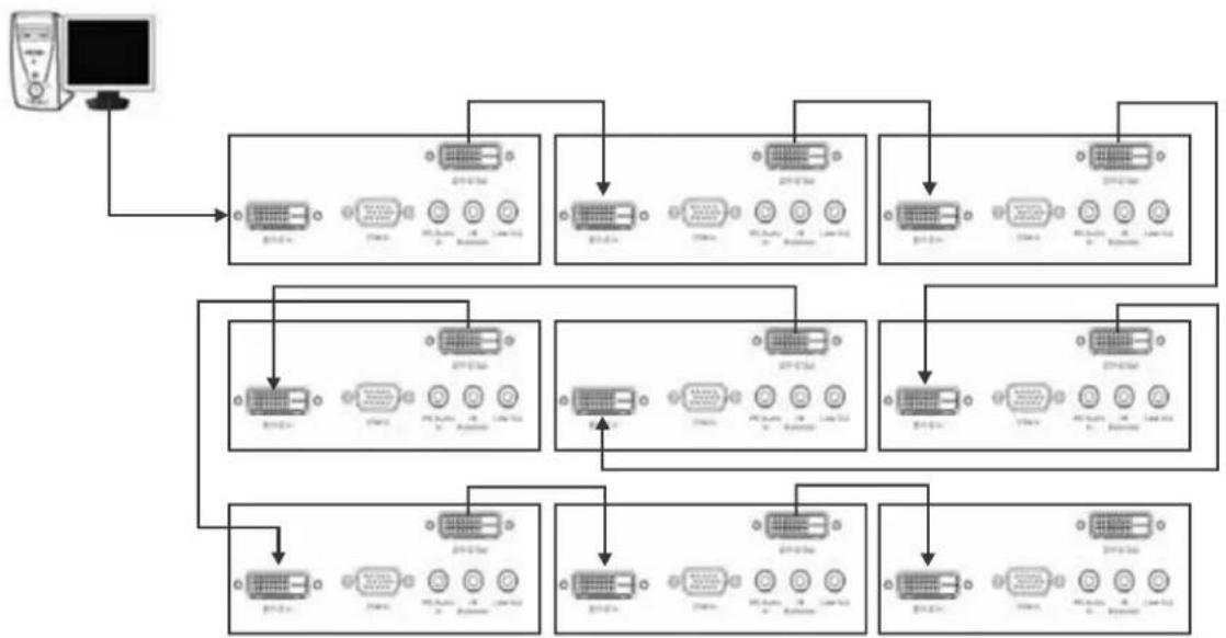
DVI Routing
A maximum daisy chain of 9 DVI connections from a single source is supported. The illustration below is an example of a typical DVI daisy chain configuration. A DVI/VGA splitter may be used to distribute the video signal to support larger video wall configurations.
NOTE: No routing order is required.
flowchart
graph TD
    A["Computer"] --> B["219-6-34 Microcontroller"]
    B --> C["219-6-34 Bus"]
    B --> D["219-6-34 Control Unit"]
    B --> E["219-6-34 Bus"]
    B --> F["219-6-34 Control Unit"]
    B --> G["219-6-34 Bus"]
    B --> H["219-6-34 Control Unit"]
    B --> I["219-6-34 Bus"]
    B --> J["219-6-34 Control Unit"]
    B --> K["219-6-34 Bus"]
    B --> L["219-6-34 Control Unit"]
    B --> M["219-6-34 Bus"]
    B --> N["219-6-34 Control Unit"]
    B --> O["219-6-34 Bus"]
    B --> P["219-6-34 Control Unit"]
    B --> Q["219-6-34 Bus"]
    B --> R["219-6-34 Control Unit"]
    B --> S["219-6-34 Bus"]
    B --> T["219-6-34 Control Unit"]
    B --> U["219-6-34 Bus"]
    B --> V["219-6-34 Control Unit"]
    B --> W["219-6-34 Bus"]
    B --> X["219-6-34 Control Unit"]
    B --> Y["219-6-34 Bus"]
    B --> Z["219-6-34 Control Unit"]
    B --> AA["219-6-34 Bus"]
    B --> AB["219-6-34 Control Unit"]
    B --> AC["219-6-34 Bus"]
    B --> AD["219-6-34 Control Unit"]
    B --> AE["219-6-34 Bus"]
    B --> AF["219-6-34 Control Unit"]
    B --> AG["219-6-34 Bus"]
    B --> AH["219-6-34 Control Unit"]
    B --> AI["219-6-34 Bus"]
    B --> AJ["219-6-34 Control Unit"]
    B --> AK["219-6-34 Bus"]
    B --> AL["219-6-34 Control Unit"]
    B --> AM["219-6-34 Bus"]
    B --> AN["219-6-34 Control Unit"]
    B --> AO["219-6-34 Bus"]
    B --> AP["219-6-34 Control Unit"]
    B --> AQ["219-6-34 Bus"]
    B --> AR["219-6-34 Control Unit"]
    B --> AS["219-6-34 Bus"]
    B --> AT["219-6-34 Control Unit"]
    B --> AU["219-6-34 Bus"]
    B --> AV["219-6-34 Control Unit"]
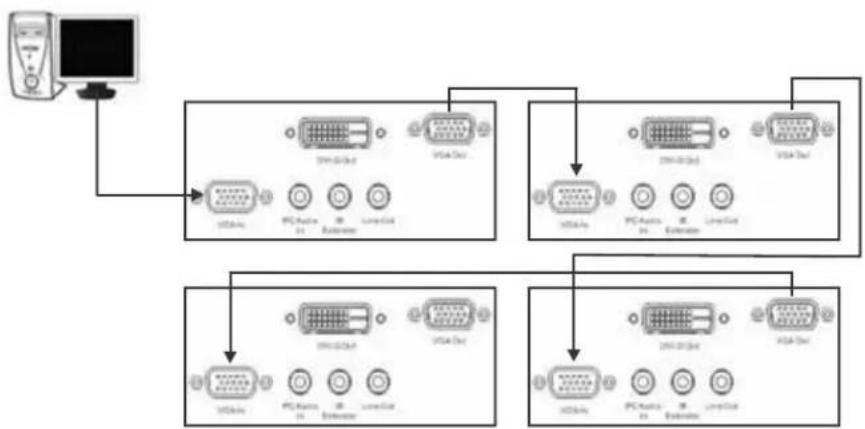
VGA Routing
A maximum daisy chain of 4 VGA connections from a single source is supported. The illustration below is an example of a typical VGA daisy chain configuration. A DVI/VGA splitter may be used to distribute the video signal to support larger video wall configurations.
NOTE: No routing order is required.
flowchart
graph TD
    A["Monitor"] --> B["Switch"]
    B --> C["100000000000"]
    B --> D["100000000000"]
    B --> E["100000000000"]
    B --> F["100000000000"]
    B --> G["100000000000"]
    B --> H["100000000000"]
    B --> I["100000000000"]
    B --> J["100000000000"]
    B --> K["100000000000"]
    B --> L["100000000000"]
    B --> M["10000000000"]
    B --> N["1000000000"]
    B --> O["100000000"]
    B --> P["10000000"]
    B --> Q["1000000"]
    B --> R["1.5GHz"]
    B --> S["2.5GHz"]
    B --> T["3.5GHz"]
    B --> U["4.5GHz"]
    B --> V["5.5GHz"]
    B --> W["6.5GHz"]
    B --> X["7.5GHz"]
    B --> Y["8.5GHz"]
    B --> Z["9.5GHz"]
    B --> AA["1.5GHz"]
3.5 Cable Tether Kit (for FHD551-X/XG only)
The Cable Tether kit consists of 2 Phillips screws and 2 cable ties. This kit is used to prevent the power cord from accidentally disconnecting. To install, secure the cable tether clip to the LCD panel using the Phillips screws, route the power cord into the channel and secure using the cable ties.
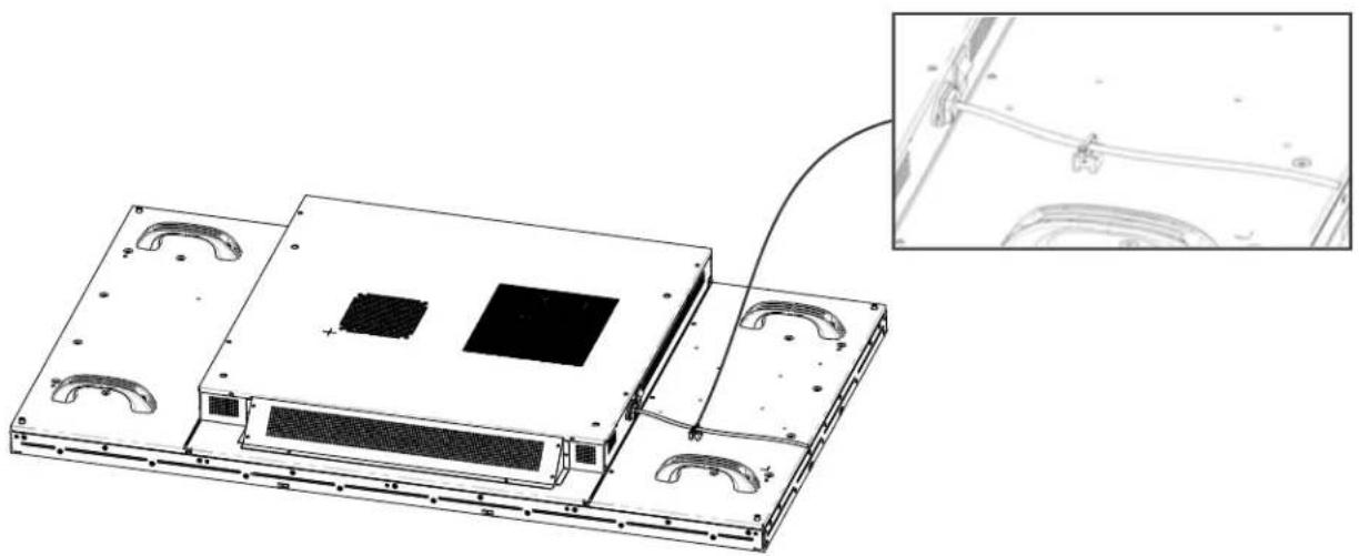
natural_image
Technical line drawing of a server rack with mounting holes and a close-up inset showing internal components (no text or symbols)3.6 Cooling Requirements
⚠ WARNING Failure to comply with the following could result in death or serious injury:
- Slots and openings in the back and bottom of the cabinet are provided for ventilation. For reliable operation and to protect from overheating do not obstruct the rear cover vents of the LCD panels.
- A minimum clearance is required behind the panels for proper ventilation:
FHD551-X/XG, 3.1" (79.3 mm) clearance
FHD461-X, 0.69" (17.5 mm) clearance
- Ambient air temperature behind the panel must be maintained at <40^ C (104° F). To make sure that the air behind each LCD panel is within the operating range. Large displays may require additional space to maintain ambient temperatures.
- A distance of at least 3 ft (914.4 mm) should be maintained between the monitor and any heat source, such as radiator, heater, oven, amplifier, and so on. Do not install the product close to smoke. Operating the product close to smoke or moisture may cause fire or electric shock.
- Do not place the LCD panel inside an enclosure (for example, a bookcase or cabinet) unless proper ventilation is provided.
- When moving the monitor from an area of low temperature to an area of high temperature, condensation may form on the housing. Do not enable power to the monitor immediately after this to avoid causing fire, electric shock, or component damage.
3.7 Runtime
Although the power supply and panel components support continuous 24/7 operation, static content must not be displayed over long periods of time (>20h per day) or image retention may occur. Powering the unit off or using power management for 4 hours per day will extend the life of the product and minimize the risk of image retention. In circumstances where a static image must be displayed over long periods of time, activating the Image Retention Frame Motion (IRFM) feature helps to avoid image retention. For details, see 4.3.8 Advanced Settings Menu, on page 4-9.
3.8 Application Software
To download the Video Wall Toolbox go to www.christiedigital.com. The main features of this software application are automatic panel mapping based on cable routing and the ability to send commands to multiple panels simultaneously. For more information, see 4.6 Video Wall Toolbox, on page 4-15.
4 Operation
This section explains how to install and connect the LCD panel. Illustrations are graphical representations only and are provided to enhance the understanding of the written material.
4.1 LCD Panel Setup
⚠ WARNING Failure to comply with the following may result in death or serious injury:
- The monitor should be operated only from the type of power source indicated on the label. If you are not sure of the type of power supplied at your location, consult your dealer or local power company.
- Make sure suitable regional line cords for the specific country are used with your setup. Refer to local regulations. See Section 1 Product Overview, for details.
- Do not overload power strips and extension cords. Overloading can result in fire or electric shock.
- Only the marked power source can be used for the product. Any power source other than the specified one may cause fire or electric shock.
- To avoid electric shock, avoid handling the power cord during electrical storms.
- To avoid the risk of electric shock or component damage, disable power before connecting other components to the monitor.
NOTICES: 1) The wall socket must be installed near the equipment and be easily accessible. 2) Before connecting, turn the monitor and any connecting source equipment OFF. After all connections are made, turn the monitor ON before any other devices. 3) When connecting to a computer, make sure that the computer is the last device powered ON, after all connections are made. 4) Read the Operation Manuals of the video source equipment before making the connections.
4.1.1 Video Source Connections
| Connection Description | |
| Power Cord Plug the supplied power cord into the AC socket on the side of the monitor. | |
| High Definition Multimedia Interface (HDMI) | Use an HDMI cable when connecting to video sources that utilize HDMI output. |
| Component (Y, Pb, Pr) | Use Component (Y, Pb, Pr) when connecting to video equipment. |
| S-video Use S-video to connect to video equipment. | |
| HD-15 for VGA and DVI | Connect the monitor to the computer using an HD 15-pin VGA/DVI cable. Secure the cable connector by tightening the screws on both sides of the plug. |
| Video Use Video to connect to composite video. | |
| Display Port | Use display port cable to connect to video/graphics equipment. |
4.2 Enabling Power
WARNING
- Hold the power connector when removing the power cable. Pulling the power cable itself may damage the wires inside the cable and cause fire or electric shock.
- When the product will not be used for an extended period of time, unplug the power connector.
- To avoid risk of electric shock, do not touch the connector with wet hands.
4.2.1 Connect the Power Cable
Connect the power cord to the power cord connector on the side of the monitor. Plug the power cord into an AC wall socket and press the power switch to I to power ON, or O to power OFF the monitor.
NOTE: To prevent the power cord from accidentally disconnecting, install the Cable Tether Kit. For details, see 3.5 Cable Tether Kit (for FHD551-X/XG only), on page 3-5.
4.2.2 Enable Power
Once the power switch is On, press the Power ON button on the side of the monitor or from the remote control.
4.2.3 Select Input Source
To select the input source for the monitor, press the Source button on the control panel or press the required source key on the remote control.
4.2.4 Disable Power
To power the monitor Off, press the Power OFF button on the control panel or from the remote control.
4.3 On-screen Display (OSD)
⚠️ CAUTION Insert batteries in accordance with the instructions found inside the battery compartment. Incorrect polarities may cause damage and leakage of the batteries, operator injury, and contamination to the remote controller. Failure to comply could result in minor or moderate injury.
NOTE: Connect the required external source equipment to the monitor before following the procedures below.
4.3.1 OSD Remote Control
The controls of the remote can be locked or unlocked by pressing the following keys in sequence: Enter, Enter, Exit, Exit, Enter, and Exit.
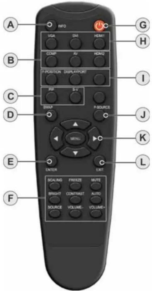
| # FUNCTION DESCRIPTION | ||
| A INFO Provides source and resolution information. | ||
| B COMP Selects the Component source. | ||
| C PIP Turns the Picture-In-Picture feature ON and OFF. | ||
| D SWAP Swaps the main source and sub-source picture. | ||
| E Enter Selects the highlighted menu choices. | ||
| F Scaling Toggles between different aspect ratios (Full Screen, Native, Letter Box, and Pillar Box). | ||
4.3.2 OSD Menu Overview
4.3.3 Image Settings Menu
The Image Settings menu allows you to make common image adjustments.
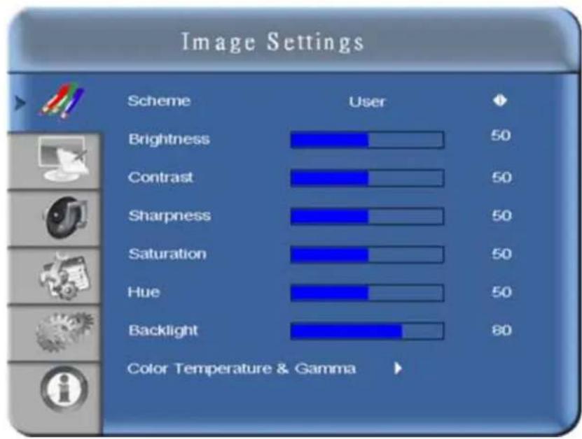
| Setting Description Range Default | |||
| Scheme | Click the left and right arrow keys to select between User, Vivid, Cinema, Game, and Sport. | User | |
| Brightness | Increases or decreases picture brightness. Click the left and right arrow keys to specify the required level. To apply the setting, press Enter. | 0~100 50 | |
| Contrast Increases or | decreases picture contrast. To specify the required level, click the left and right arrow keys. To apply the setting, press Enter. | 0~100 50 | |
| Sharpness | Adjusts picture definition. To specify the required level, click the left and right arrow keys. To apply the setting, press Enter. | 0~24 12 | |
| Saturation Adjusts brilliance and brightness when operating in Video mode only. To specify the required level, click the left and right arrow keys. To apply the setting, press Enter. | 0~100 50 | ||
| Hue Increases or decreases the green hue when operating in Video mode only. To specify the required level, click the left and right arrow keys. To apply the setting, press Enter. | 0~100 50 | ||
| Back Light Adjusts the back light. | 0~100 60 | -FHD461-X | 80 - FHD551-X AND FHD551-XG |
| Color Temp and Gamma | Adjusts the red, green and blue gains, as well as the red, green, and blue offsets. See 4.3.4 Image Settings—Color Temp and Gamma, on page 4-5. | ||
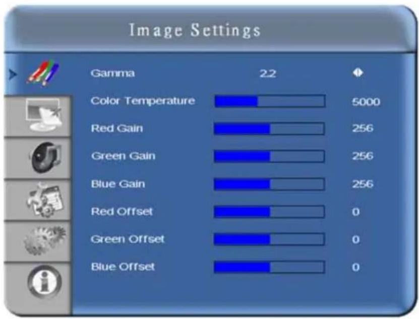
4.3.4 Image Settings—Color Temp and Gamma
bar
Image Settings | Category | Gamma | Value | |---|---|---| | Color Temperature | 22 | 5000 | | Red Gain | 22 | 256 | | Green Gain | 22 | 256 | | Blue Gain | 22 | 256 | | Red Offset | 22 | 0 | | Green Offset | 22 | 0 | | Blue Offset | 22 | 0 || Setting Description Range Default | |||
| Gamma Options include Off and 2.2. | |||
| Color Temperature Options include User mode and ranges of 3200K to 9600K. Values increment by 100K. | |||
| Red, Green, and Blue Gain | To adjust these settings, make sure Color Temperature is set to User mode. | 128~383 | 256 |
| Red, Green and Blue Offset | To adjust these settings, make sure Color Temperature is set to User mode. | 50~50 | 0 |
4.3.5 Display Settings Menu
This menu is used for common source adjustments.
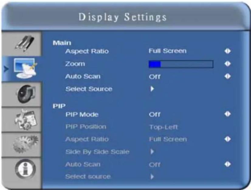
Main
| Setting Description Range Default | |||
| Aspect Ratio | To change the picture aspect ratio, click the left and right arrow keys. Options include: Full screen, Pillar Box, Letter Box, and Native. | Full screen | |
| Zoom To zoom in and out on the display, click the left and right arrow keys. 0~10 0 | |||
| Auto Scan | When enabled, the signal is searched automatically by order VGA, HDMI1, HDMI 2, DVI, Display Port, Composite Video, S-video, or Component. | ON | |
| Select Source Source selections include: VGA, HDMI 1, HDMI 2, DVI, Display Port, S-Video and Video, and Component. | VGA | ||
PIP
| Setting Description Default | ||
| PIP Mode | To scroll through the available PIP modes, click the left and right arrow keys. Modes include: Off, Large PIP, Medium PIP, Small PIP, and Side-by-Side. | Off |
| PIP Position | Chose from Bottom-Right, Top-Left, Top-Right, and Bottom-Left. | Bottom-Right |
| Aspect Ratio | To scroll through the available aspect ratios, click the left and right arrow keys. Options include: Full screen, Pillar Box, and Letter Box. | Full screen |
| Side by Side Scale | Select from Zoom In, Zoom Out, Main, PIP, Default, and Return. | |
| Auto Scan Enables or | disables Auto Scan. ON | |
| Setting | Description | Default |
| Select Source | Source selections for PIP include; HDMI 1, HDMI 2, DVI, Display Port, S-Video and Video, and Component. There are three types of inputs, each containing their own set of PIP sources (see table below). When setting up PIP you must select one of the sources within the input to display PIP. For example, if using Analog you must select from Component, Composite, S-video, or RGB-VGA. If using Analog and with DVI selected the PIP feature will not work | Video |
Inputs
| Analog Inputs Digital 1 Inputs Digital 2 Inputs | ||
| Component DVI Display | Port | |
| Composite HDMI-1 | ||
| S-video HDMI-2 | ||
| RGB-VGA | ||
4.3.6 Audio Settings Menu
This menu is used to adjust volume settings.
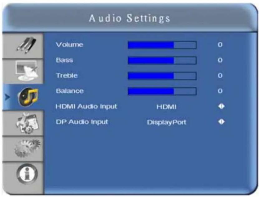
| Setting | Description | Range | Default |
| Volume | To adjust the volume level, click the left and right arrow keys. To apply the setting, press Enter. | 0~100 | 50 |
| Bass | To adjust the bass level (low tones), click the left and right arrow keys. To apply the setting, press Enter. | 0~20 | 10 |
| Treble | To adjust treble (high tones), click the left and right arrow keys. To apply the setting, press Enter. | 0~20 | 10 |
| Balance | To adjust the left and right speakers, click the left and right arrow keys. To apply the setting, press Enter. | 0~20 | 10 |

4.3.8 Advanced Settings Menu
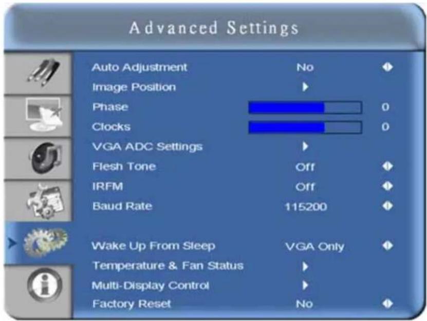
| Setting Description Range Default | |||
| Auto Adjustment | Forces the monitor to acquire and lock to the input signal. This is useful when the signal quality is marginal. This feature does not continually require the signal. | ||
| Image Position Adjusts image location (only VGA Mode). | |||
| Phase Only VGA Mode 0~63 | |||
| Clocks Only VGA Mode 0~100 | |||
| VGA ADC Settings | Select from ADC setting, User ADC Calibration, and Restore Factory Default ADC settings. | ||
| Flesh Tone | Options include; Off, Low, Medium, and High (only Video Mode) | Off | |
| IRFM | Creates slight frame motion to help avoid image retention. | Off | |
| Baud Rate | Set baud rate to 115200, 38400, 19200, or 9600. | 115200 | |
| Wake Up From Sleep | Click the left and right arrow keys to set how the panel wakes up from sleep (Power Savings) mode.Select VGA Only when you want the panel to wake up after receiving a video signal through its VGA input. The panel enters a sleep mode when it has not received a video signal for 5 minutes.Select VGA, Digital, RS232 when you want the panel to wake up after receiving a video signal through its DisplayPort, HDMI, DVI, or VGA inputs.NOTE: When in sleep mode, the RS232 port remains active and can receive commands. The panel enters sleep mode when it has not received a video signal for 5 minutes.Select Never Sleep when you do not want the panel to enter sleep mode. | VGA Only | |
| Setting | Description | Range | Default |
| Temperature and Fan Status | To display the status of the thermal sensor, set to Temperature. To display the status of the cooling fans, set to Fan 1 Speed or Fan 2 Speed. | ||
| Multi-Display Control | See 4.3.9 Advanced Settings Menu continued, on page 4-10. | ||
| Factory Reset Restores | all settings to their default. | ||
4.3.9 Advanced Settings Menu continued
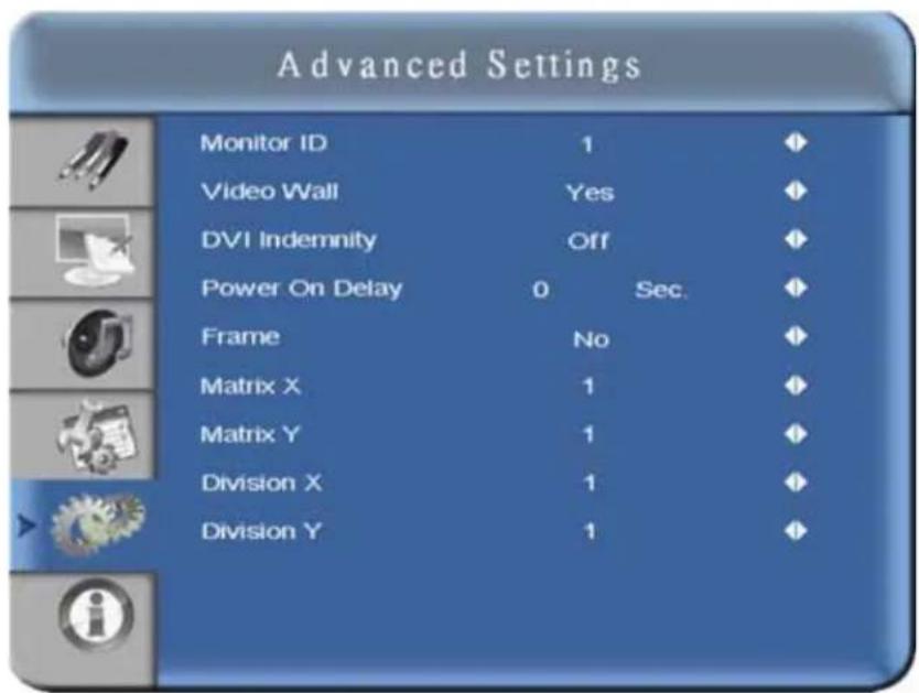
| Setting Description Default | ||
| Monitor ID | Each display must have a unique monitor ID. To set the monitor ID, click the left and right arrow keys. | |
| Video Wall | Toggles between single display mode and video wall mode, where the source signal can be displayed on up to 9 displays. Options include Yes and No. | No |
| DVI Indemnity | Manually compensates for image degradation caused from daisy-chaining too many monitors using DVI cable. It is recommended to enable DVI Indemnity for the 7th~9th monitors within a DVI daisy-chain. | |
| Power On Delay | To select from 0-30,000 msec (steps in increments of 50msec), click the left and right arrow keys. | |
| Frame | When set to On, the display adjusts the image to compensate for the width of the display bezels to accurately show the image. Options include Yes and No. | |
| Matrix X/Matrix Y | Defines the size of the video wall matrix. To select between 1-5, use the left and right arrow keys. | |
| Division X/Division Y | Defines the position of each display within the video wall matrix. To select between 1-5, use the left and right arrow keys. | |
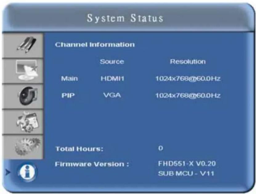
4.3.10 System Status Menu
This read-only menu provides information on the active sources and the latest firmware version.
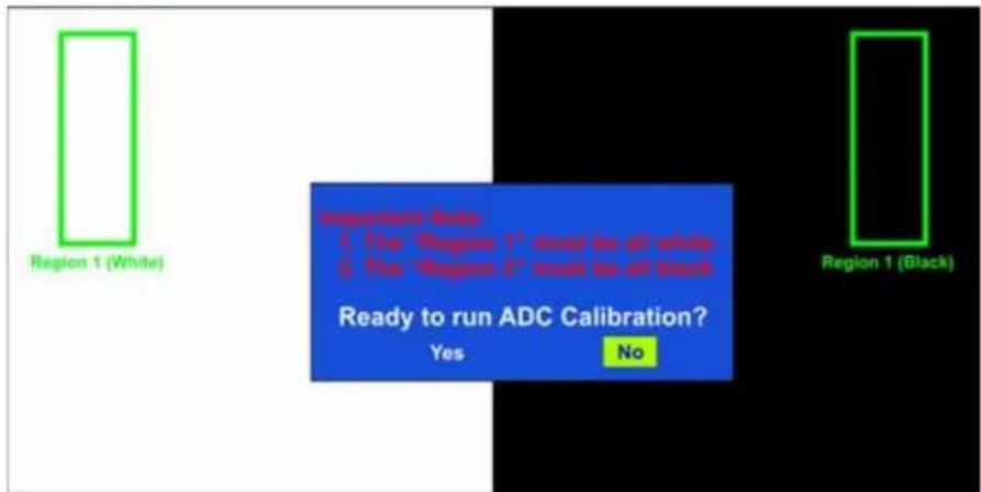
User ADC Calibration
- When using VGA as a signal source, go to Advanced Settings in the OSD menu and select VGA ADC Settings, then choose User ADC Calibration.
A warning message appears to make sure the proper image is displayed on screen before ADC calibration begins.
a. The images in the green boxes, displayed on both sides of the screen, must be white and black to run the calibration accurately.
NOTE: The white in the left green box has to be the brightest white and the black in the right green box has to be the darkest black.
-
After the proper image is displayed, click Yes to begin ADC calibration.
-
During the calibration process, the following image appears to notify the user to wait for the calibration.
User ADC Calibration... Please Wait!
- After calibration is completed, the display notifies the user if the process was completed successfully or if it failed.
User ADC Calibration Finish!
User ADC Calibration Failure!
4.4 Video Wall Matrix Setup
A video wall matrix consists of spanning a single video signal across multiple panels. A DVI source can be stretched across a maximum of 9 panels and a VGA or composite source can be stretched across a maximum of 4 panels. For a DVI source, the maximum matrix dimensions are 3 wide by 3 high and for a VGA or composite source the maximum dimensions are 2 wide by 2 high.
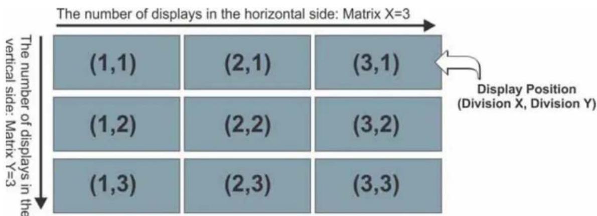
4.4.1 Example: 3x3 Screen Matrix (9 displays)
NOTES: 1) Number of connecting devices for tiling mode: Max. of DVI=9, VGA=4, Video=4.
2) Cable length between displays for tiling mode (Max. 3m).
geo
| Vertical Side | Matrix X | (1,1) | (2,1) | (3,1) | |---|---|---|---|---| | Vertical Side | X=3 | (1,2) | (2,2) | (3,2) | | Vertical Side | Y=3 | (1,3) | (2,3) | (3,3) |4.4.2 Video Wall Parameters
| Parameter Description | |
| Monitor ID | To control a monitor or multiple monitors daisy-chained by RS232, each monitor should have a unique Monitor ID. Monitor IDs can be assigned from 1-25 for looping function only. It is recommended to number each monitor in a RS232 daisy chain sequentially from 1.NOTES: 1) DVI input can support up to a 3x3 matrix and loop through directly. 2) VGA and video input can support up to 2x2 matrix and loop through directly. |
| Video Wall Enables or disables the video wall feature. | |
| DVI Indemnity | Manually compensates for image degradation caused from daisy-chaining too many monitors using DVI cable. It is recommended to select DVI Indemnity as On for the 7^th - 9^th monitors within a DVI daisy-chain. |
| Power On Delay | Enable or disable the frame compensation feature. For details, see 4.7 Frame Compensation, on page 4-17. |
| Frame When set to On, the display adjusts the image to compensate for the width of the display bezels to accurately show the image. Options include Yes and No. | |
| Matrix X | Number of monitors arranged horizontally. Matrix X can range from 1-3 by connecting with a DVI source; 1-2 by VGA or video source of monitor directly. |
| Matrix Y | Number of monitors arranged vertically. Matrix Y can range from 1-3 by connecting with a DVI source; 1-2 by VGA or video source of monitor directly. |
| Division X | Select which section in horizontal direction to be located for this monitor. |
| Division Y Select which section in vertical direction to be located for this monitor. | |
4.4.3 Setup Video Wall Parameter on OSD Menu
- To access the OSD menus, press Menu from the remote control or the keypad.
- To navigate to the Advanced Settings page, press the up or down arrow keys.
- To access the Advanced Settings page, shown below, press the right arrow key.
- Navigate to the Multi-Display Control field.
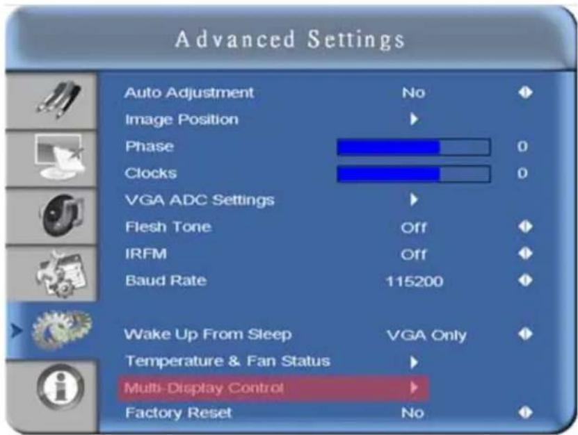
- To access the video wall settings, shown below, press the right arrow key.
The Video Wall setting defaults to No.
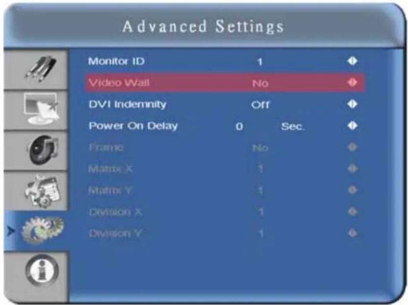
-
To change the Video Wall setting to Yes, use the right arrow key from the remote control. To navigate through the sub-items, press the up and down arrow keys. To adjust the values, press the left and right arrow keys to adjust the values.
-
To exit, press Menu.
4.4.4 Setup Video Wall Parameters using RS232
See Appendix A RS232 Command Format.
4.4.5 Setup Video Wall Parameters using Video Wall Toolbox
See 4.6 Video Wall Toolbox, on page 4-15.
4.5 RS232 Control
NOTICES: 1) The following procedure should only be performed by advanced users. 2) The Video Wall Toolbox software may be used to send direct commands using RS232, or alternatively a software terminal application may be used, providing it supports transmission of hexadecimal characters.
You control an array of panels together using a computer with an RS232 terminal or the Video Toolbox application. Controlling the LCD monitors through RS232 is typically used when managing a large array. You can also control the monitors using IR extenders and the remote control; however, this can be inefficient when dealing with large arrays. For details, see 3.2 Remote Requirements, on page 3-1.
To function correctly, the RS485 OUT terminal can only be connected to another monitor of the same series model. The maximum that can be connected together in this way is 25 panels. For cabling guidelines, see 3.4 Cabling, on page 3-3.
For a list of the RS232 commands, see Appendix A RS232 Command Format.
- RS232: only supports 9 pin serial straight cable; crossover or Null modem cable are not supported
- RS485: only support Cat-5 straight cable; crossover cable is not supported
4.6 Video Wall Toolbox
Use the Video Wall Toolbox application to control all display parameters for an individual LCD panel or multiple panels within a video wall. The application supports an Auto Setup feature, which automatically configures display ID, matrix size, and positions for each panel within a single source video wall.
NOTE: Make sure the correct COM port is selected prior to sending commands. If a COM port is not available, a USB to RS232 converter may be used.
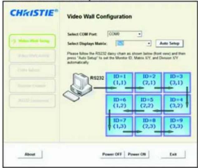
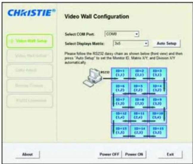
4.6.1 Automatic Video Wall Setup
The Video Wall Toolbox can automatically setup a single source video wall, providing the cable routing adheres to the supported configurations, as described in 3.4 Cabling, on page 3-3.
Example of a 3x3 Screen Matrix with a Single Source
-
Download the Video Wall Toolbox at www.christiedigital.com.
-
Once the software is loaded, click Video Wall Setup.
-
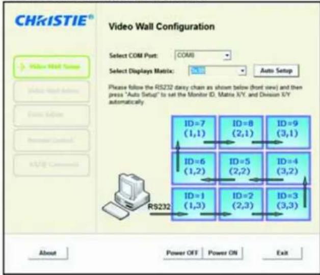
From the Select Display Matrix list select 3x3 for RS232 wired from top-left or 3x3B for RS232 wired from bottom-left.
-
To send the information to each panel in your video wall, click Auto Setup.
RS232 wired from top-left
RS232 wired from bottom-left
4.6.2 Manual Video Wall Setup
Use the Video Wall Toolbox to configure complex video walls where multiple video sources are required.
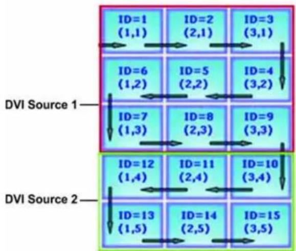
Example of a 3x5 Video Wall with 2 DVI Sources
The illustration below depicts a 3x5 video wall with the first source spanning across the top 3x3, and the second source spanning across the bottom 3x2.
flowchart
graph TD
    A["DVI Source 1"] --> B["ID=1 (1,1)"]
    A --> C["ID=2 (2,1)"]
    A --> D["ID=3 (3,1)"]
    A --> E["ID=6 (1,2)"]
    A --> F["ID=5 (2,2)"]
    A --> G["ID=4 (3,2)"]
    A --> H["ID=7 (1,3)"]
    A --> I["ID=8 (2,3)"]
    A --> J["ID=9 (3,3)"]
    K["DVI Source 2"] --> L["ID=12 (1,4)"]
    K --> M["ID=11 (2,4)"]
    K --> N["ID=10 (3,4)"]
    K --> O["ID=13 (1,5)"]
    K --> P["ID=14 (2,5)"]
    K --> Q["ID=15 (3,5)"]
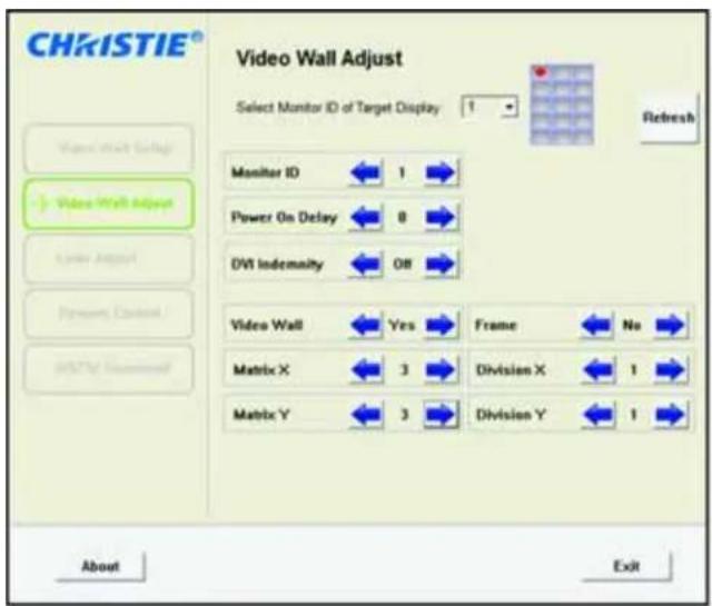
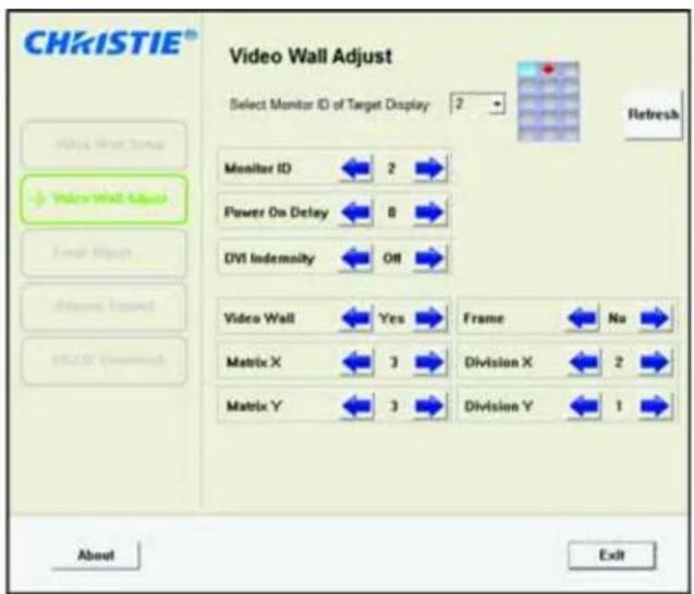
- To assign unique monitor ID's to each display within the 3x5 video wall, from the Video Wall Toolbox software, click Auto Setup.
- Click Video Wall Adjust to configure the Matrix X,Y and Division X,Y parameters for each display by selecting the appropriate display location within the video wall graphic.
The display location is identified by a red dot. The illustration below gives an example of how to configure the first 2 displays.
4.7 Frame Compensation
If powered ON, the display adjusts the image to compensate for the width of the display bezels to accurately show the image.
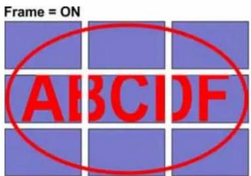
Part of the signal will go behind the bezel area.
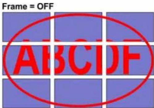
To show full signal on each display.
5 Troubleshooting
5.1 No Image
| Check Correction | |
| Is the power cord of the monitor connected? | Check to make sure the power cord is connected properly to the power outlet.Make sure the main power switch is in the “T” position. |
| Is the power indicator amber? | If yes, press the ON button from the remote control or the control panel. |
| Are both the S-video input and AV2 input connected? | If yes, remove either the S-video input or AV2 input. |
5.2 Screen Color Abnormal
| Check Correction | |
| Is the screen color unstable or monochrome? | Check the source cable connection to make sure there is a proper fit. |
| Are black dots visible on the screen? | Clean the screen surface using a soft cloth. |
| Do you see partial blurring on the screen? | This happens due to interference from surrounding magnetic fields, as created when speakers, steel structures, or high-voltage lines are placed near the monitor. Remove such materials from the immediate vicinity and use the OSD menu to adjust the screen. |
5.3 Flickering Screen
- Remove any highly magnetic material away from the monitor.
- Adjust the graphic interface (PC mode) within allotted frequency parameters.
5.4 Picture is Dark
Adjust the backlight and brightness. It takes several seconds for the monitor to warm up after the power is enabled.
5.5 Picture Ghosting
Make sure the source equipment connection cables are less than 15 meters (50ft). If additional length is required, contact your authorized dealer for a signal amplifier (not provided).
5.6 Picture Size is Incorrect
Adjust picture format to the required image size. For details, see 4.3.5 Display Settings Menu, on page 4-6.
5.7 White Color is Incorrect
Adjust the color temperature or alter the User settings to preferred settings. For details, see 4.3.3 Image Settings Menu, on page 4-4.
5.8 Screen Image Not Centered
Adjust picture format to required image size. For details, see 4.3.5 Display Settings Menu, on page 4-6.
5.9 Remote Control Not Functioning
- Make sure the IR extended cable is installed correctly.
- Check the remote key and keypad lock/unlock function.
- Replace the battery.
6 Specifications
Due to continuing research, specifications are subject to change without notice.
6.1 LCD Panel
| Item FHD551-X FHD551-XG FHD461-X Unit | ||||
| Resolution HDTV format | 1920x1080 / | |||
| Max. Brightness 700 630 | 700 cd/m2 | |||
| Contrast Ratio 3000:1 27 | 00:1 4000:1 / | |||
| Response Time | Typ. 8 | Typ. 6 | ms | |
| Aspect Ratio | 16:9 | / | ||
| Driver Element | a-Si TFT active matrix | / | ||
| Display Colors | 8 bit, 16.7m | 10 bit, 1073.7m | Colors | |
| Number of Pixels | 1,920 x 1080 | Pixel | ||
| Pixel Pitch 0.63(H) x 0.63(W) | 0.53(H) x 0.53(W) mm | |||
| Pixel Arrangement | RGB vertical stripe | |||
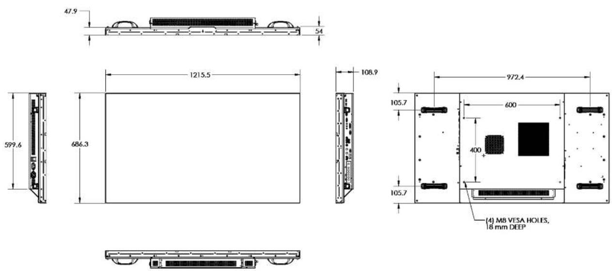
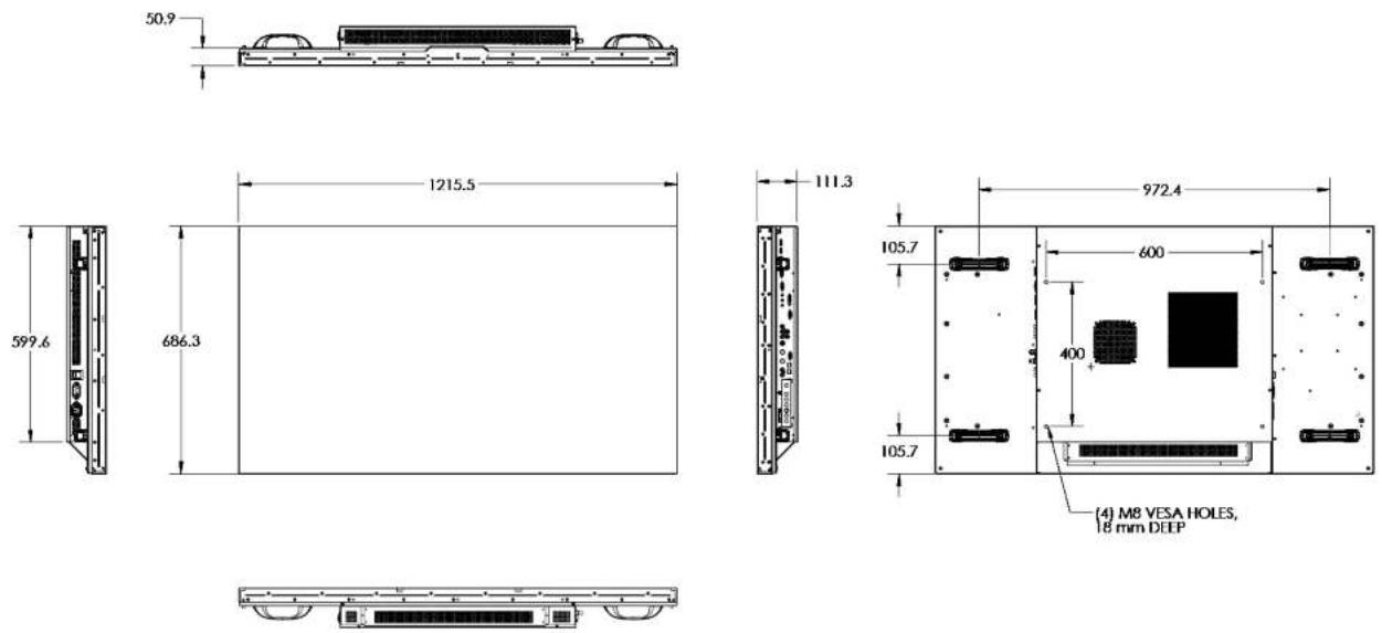
6.2 Physical Dimensions
| FHD551-X | FHD551-XG | |
| Dimensions | • 1215.5 mm x 686.3 mm x 108.9 mm (W x H x D)• 47.85" x 27.01" x 4.29" (W x H x D) | • 1215.5 mm x 686.3 mm x 111.3 mm (W x H x D)• 47.85" x 27.01" x 4.38" (W x H x D) |
| Weight | 34 kg (75 lbs.) | 41 kg (90 lbs.) |
| Weight with packaging | 45 kg (99 lbs.) | 52 kg (115 lbs.) |
| FHD461-X | |
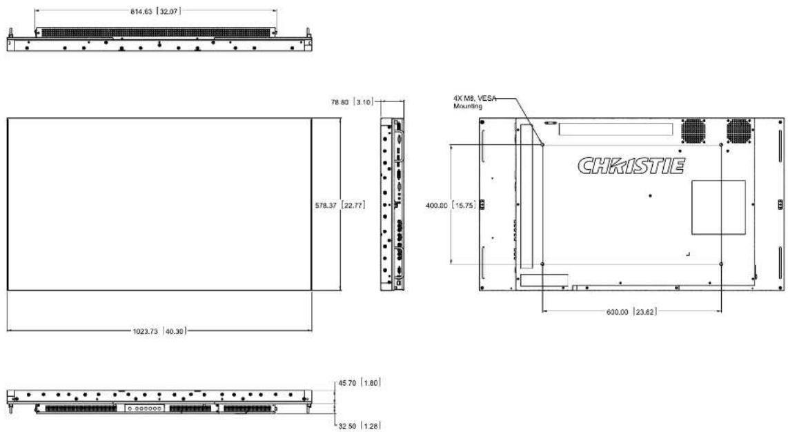
| Dimensions | • 1023.7 mm x 578.3 mm x 77.2 mm (W x H x D)• 40.30” x 22.77” x 3.04” (W x H x D) |
| Weight | 26.5 kg (58.4 lbs.) |
| Weight with packaging | 30 kg (66.1 lbs.) |
6.3 Graphic
| Item Specification | |
| Separate Sync. LVDS level | |
| Horizontal Sync. Positive/Negative | |
| Vertical Sync. Positive/Negative | |
| Input Connector Display Port/ HDMIx2/ VGA/ DVI/ PC Audio IN/ IR extender/ Component/ Audio IN (for Component)/ S-V/ Video / Audio IN (for S-V or AV) | |
| Output Connector(Notes 1,2) | VGA OUT/ DVI OUT/ Line OUT/Video |
NOTES: 1) Number of connecting devices for tiling mode: Max. of DVI=9, VGA=4, Video=4.
2) Cable length between displays for tiling mode (max. 3 m).
6.4 Scan Rate
| Item Specification Unit | ||
| Horizontal | 31~91 KHz | |
| Vertical | 56~85 Hz | |
6.5 Performance
| Item Specification | |
| Auto Adjust | Clock, Phase, H-position and V-position (VGA only) |
| Screen Scaling | VGA/ SVGA/ XGA/ WXGA/ HDTV Full Screen Display |
| Power Management | VESA DPMS, DVI DMPM |
| Color Adjustment | 3200K to 9600K (step by 100K), User |
| OSD Language | English, Simplified Chinese, French, German, Italian, Portuguese, Russian, Spanish, Japanese and Korean |
6.6 Power Source
| Item Specification | |
| Power Input | AC100~240V 5A, 50/60Hz (worldwide) |
| Power Consumption | |
| FHD551-X/XG | 175 typical, ≤ 0.5W STANDBY* |
| 275W maximum | |
| FHD461-X | 105W typical, ≤ 0.5W STANDBY** |
| 170W maximum | |
*NOTE: To restrict power consumption during STANDBY mode to ≤0.5W, Wake Up from Sleep must be set to VGA only (see 4.3.8 Advanced Settings Menu).
**NOTE: For power consumption to be ≤0.5W, Wake Up from Sleep shall be set to VGA Only.
6.7 LCD Quality Inspection
FHD551-X/XG, FHD461-X utilizes a commercial grade LCD, which is rigorously inspected for quality prior to shipment. Due to the nature of the manufacturing process, some minor inconsistencies may occur in the LCD. The following section describes some of the key quality inspection criteria, and what is considered acceptable.
6.7.1 Pixels
Each pixel in the LCD is comprised of 3 dots: red, green, and blue. With typical content and viewing distances, these dots are too small to detect. Each panel is inspected under specific measurement conditions, as indicated in the table below.
| Defect Type Acceptance Criteria | |
| Bright Dot | |
| Random N=3 | |
| 2 Adjacent N=1 | |
| 3 Adjacent N=0 | |
| Dark Dot | |
| Random N<=10 | |
| 2 Adjacent N<=2 sets | |
| 3 Adjacent N<=1 | |
| Distance between dark dots L<=5mm | |
| Total amount of dots | N<=15 |
6.7.2 Uniformity
A small area of the screen may include slight variations on uniformity. In particular, due to the narrow bezel on the display, there may be faint shadows on the extreme edge of the screen due to the underlying construction of the LCD panel. With typical content and viewing distances, these variations are not noticeable.
6.8 Environment
- Storage Temperature Min. -20^ (-4^) Max. 50^ (122^)
- Operating Temperature Min. 5^ (41°F) Max. 40^ (104°F)
- Relative Humidity 20 - 90% non-condensing
6.9 DDC
- Plug & Play DDC 2Bi Compliance
6.10 Function
- OSD Key 7 keys
• Wall Mount VESA 600 x 400 mm (23.6" x 15.7") - Communication Port D-sub 9 Pin IN, RJ45 IN/OUT
6.11 RS232 1:N Control
• Max. Looping Quality 25 set
• Max. Cable Length of CAT5 between 2 Displays 100m
- System Reboot Time (Note 1) 5 sec.
- “Read” Response Time@Baudrate 115200 (Note 2) Min. 36/ Typ. 46/Max. 300 ms
- “Write” Response Time@ Baudrate 115200 Min. 36/Typ. 459/Max. 1200 ms
• Transmission Time@ Baudrate 115200 (Note 3)
• Monitor No. 4 300 (Typ.)
• Monitor No. 9 800 (Typ.)
• Monitor No. 16 1500 (Typ.)
• Monitor No. 25 2400 (Typ.)
NOTES: 1) System Reboot Time: Waiting time to shutoff or start-up the monitor. 2) Response Time: Time is measured by 1 set with stable signal and without extra IR or keypad control. 3) Transmission Time: Additive delay for serially connecting extra sets. The delay also depends on the baudrate.
7 Timing Table
| Timing fII (kHz) fV (Hz) | Dot clock (MHz) | HD MI | PC | Comp- onent | S- Video | Comp- osite | DVI | Display Port | ||||
| VESA | VGA 640x480 31.469 59.94 25 | .175 | O O | /// | O ■ O | |||||||
| 37.861 72.809 31.5 | O O | /// O O | ||||||||||
| 37.5 | 75 31.5 | O O | /// O O | |||||||||
| 43.269 85.008 36 | O O | /// O O | ||||||||||
| SVGA 800x600 | 35.156 56.25 36 | O O | /// O O | |||||||||
| 37.879 60.317 40 | O O | /// O ■ O | ||||||||||
| 48.077 72.188 50 | O O | /// O O | ||||||||||
| 46.875 75 49.5 | O O | /// O O | ||||||||||
| 53.674 85.06 56.25 | O O | /// O O | ||||||||||
| XGA 1024x768 | 48.363 60.004 65 | O O | /// O ■ O | |||||||||
| 56.476 70.069 75 | O O | /// O O | ||||||||||
| 60.023 75.029 78.75 | O O | /// O O | ||||||||||
| 68.677 84.997 94.5 | O O | /// O O | ||||||||||
| WXGA 1360 x768 | 47.712 60.015 85.5 | O O | /// O ■ O | |||||||||
| 1280 x 720 | 44.444 59.98 64 | O O | /// O ■ O | |||||||||
| 44.772 59.86 74.5 | O O | /// O ■ O | ||||||||||
| 56.456 74.78 95.75 | O O | /// O O | ||||||||||
| 1280 x 768 | 47.776 59.87 79.5 | O O | /// O ■ O | |||||||||
| 47.396 59.995 68.25 | O O | /// O ■ O | ||||||||||
| 68.633 84.837 117.5 | O O | /// O O | ||||||||||
| 1280 x 800 | 49.306 59.91 71 | O O | /// O ■ O | |||||||||
| 49.702 59.81 83 | O O | /// O ■ O | ||||||||||
| SXGA | 1152x864 | 67.5 | 75 | O | // | /// O O | ||||||
| 1280x1024 63.981 60.02 O | // | /// O O | ||||||||||
| SXGA+ | 1400x1050 64.744 59.95 O | // | /// O O | |||||||||
| 1440 x 900 | 55.469 59.901 88.75 | O O | /// O O | |||||||||
| 55.935 | 59.88 106.5 | O O | /// O | O | ||||||||
| WSXGA+1680 x 1050 | 64.674 59.883 119 | O O | /// O ■ O | |||||||||
| 65.29 | 59.954 146.25 | O O | /// O ■ O | |||||||||
| UXGA 1600 x1200 | 75 | 60 | 162 | O | O ■ | / | / | / | O ■ | O | ||
| 1920 x 1080 | 66.587 | 59.93 138.5 | O O | /// O ■ O | ||||||||
| SDTV | NTSC | 15.734 | 29.97 | 13.5 | / | / | 480i | O | O ■ | / | / | |
| PAL | 15.625 | 25 | 13.5 | / | / | 576i | O | O | / | / | ||
| EDTV | 480p | 31.5 | 60 | 27.03 | O / | O | /// O ■ O | |||||
| 576p | 31.25 | 50 | 27 | O / | O | /// O ■ O | ||||||
| Timing | fH (kHz) fV (Hz) | Dot clock (MHz) | HD MI | PC | Comp- onent | S- Video | Comp- osite | DVI | Display Port | |||
| HDTV 720p1280x720 | 37.5 50 74.25 | O / O // O | ■ O | |||||||||
| 44.995 59.94 | 74.176 | O / O | // O | O | ||||||||
| 45 | 60 74.25 | O / O | // O | O | ||||||||
| 1080i1920x1080 | 28.13 | 50 74.25 | O / O | // O | O | |||||||
| 33.716 59.94 | 74.176 | O / O | // O | O | ||||||||
| 33.75 | 60 74.25 | O / O | // O | O | ||||||||
| 1080p1920x1080 | 27 | 24 74.25 | O // | /// | O | |||||||
| 28.125 25 74.25 | / | /// | /// | / | ||||||||
| 33.176 29 74.18 | / | /// | /// | / | ||||||||
| 33.75 | 30 74.25 | / | /// | /// | / | |||||||
| 56.25 | 50 148.5 | O / O | // O | O | ||||||||
| 67.433 59.94 | 148.352 | O / O | // O | O | ||||||||
| 67.5 60 148.5 | O / O | // O | O | |||||||||
NOTES: 1) 480i means supported 480i@60Hz (YPbPr) and 576i means supported 576i@50Hz (YPbPr).
2) O represents compliant timing for single display and ■ represents compliant timing for video wall.
A RS232 Command Format
A.1 RS232 Command Format
STX(1byte) + IDT(1byte) + Type(1byte) + CMD(3bytes) + [Value/Reply(1byte)] + ETX(1byte)
| STX Start byte = 07 | |
| IDT 00 (Hex) | Num) for broadcast mode, 01~19 (Hex Num) for single control mode |
| Type Read or | Write command, 01: read/action, 02: write; 00: return to host (from monitor) |
| CMD as following tables | |
| Value Setting | Value of "Write Command" |
| Reply Return | Value of monitor |
| ETX End byte = 08 | |
• Transmit from PC (Host)
- Read command: 07 IDT 01 CMD 08 (7bytes)
- Write/Setting command: 07 IDT 02 CMD VAL 08 (8bytes)
- Return from Monitor: Return CMD is the same with received CMD, the return command is sent after action. In broadcast mode, no return is sent.
A.2 Serial Port Setting
| Baud Rate | Data Bit | Parity Bit | Stop Bit |
| 115200 | 8 | none | 1 |
Baud rate can be set to 38400, 19200, and 9600 to match the monitor baud rate setting.
Baud rate 115200 is the default setting.
Explanation of symbols
●: Optional commands for advanced A/D board option
▲: Valid command on Power saving/ off mode
Table A.1 RS232 Commands
| Main Item Control Item CMD Type | Value (DEC) | Reply (DEC) | Content | CMD (HEX) | Remark | |||
| Power Control & Input Source | Power Control POW W/R | 00 00 Off (soft power) | 50 4F 57 | [AXYT] | ||||
| 01 01 On (soft power) |  | |||||||
| Input Source MIN W/R | 00 00 VGA | 4D 49 4E | ||||||
| 01 01 Digital DVI | ||||||||
| 02 02 S-Video | ||||||||
| 03 03 Video | ||||||||
| 04 04 COMP | ||||||||
| 09 09 HDMI | ||||||||
| 10 10 HDMI2 | ||||||||
| 13 13 Display Port | ||||||||
Table A.1 RS232 Commands
| Main Item | Control Item | CMD | Type | Value (DEC) | Reply (DEC) | Content | CMD (HEX) | Remark |
| Display Adjustment Display Adjustment | BRI W/R | 0~100 Current | Value | Back Light Brightness | 42 52 49 | |||
| BRL W/R | 0~100 Current | Value | Digital Brightness Level | 42 52 4C | ||||
| BLC W/R | 00 00 Off (Back Light) | 42 4C 43 | ||||||
| 01 01 On (Back Light) | ||||||||
| CON W/R | 0~100 Current | Valuc | Contrast 43 4F 4E | |||||
| HUE W/R | 0~100 Current | Valuc | Hue 48 55 45 | |||||
| SAT W/R | 0~100 Current | Valuc | Saturation 53 41 54 | |||||
| CCT W/R | 0~64 | Current | Value | Color Temperature (3200K~9600K) | 43 43 54 | |||
| GAC W/R | 00 00 Off (Gamma) | 47 41 43 | ||||||
| 01 01 2.2 (Gamma) | ||||||||
| USR W/R | 0~255 Current | Value | Red Gain (128~383) | 55 53 52 | ||||
| USG | W/R 0~255 Current | Value | Green Gain (128~383) | 55 53 47 | ||||
| USB W/R | 0~255 Current | Value | Blue Gain (128~383) | 55 53 42 | ||||
| UOR W/R | 0~100 Current | Value | Red Offset (-50~50) | 55 4F 52 | ||||
| UOG | W/R 0~00 Current | Value | Green Offset (-50~50) | 55 4F 47 | ||||
| UOB W/R | 0~100 Current | Value | Blue Offset (-50~50) | 55 4F 42 | ||||
| RXY | R | 25 bytes | Read Luminance & Color Chromaticity for 9300K | 52 58 59 | Note 1 | |||
| Adjustment | PHA | W/R 0~63 | Current Value | Phase | 50 48 41 | |||
| CLO | W/R 0~100 Current | Value | Clock | 43 4C 4F | ||||
| HOR | R | Current Value | Horizontal Position | 48 4F 52 | ||||
| VER R | Current Value | Vertical Position | 56 45 52 | |||||
| ADJ W | 00 00 Auto Adjust | 41 44 4A | ||||||
| Video Mode | SHA | W/R 0~24 | Current Value | Sharpness | 53 48 41 | |||
Table A.1 RS232 Commands
| Main Item | Control Item | CMD | Type | Value (DEC) | Reply (DEC) | Content | CMD (HEX) | Remark |
| Other Control | PIP Adjust PSC W/R | 00 00 PIP | OFF | 50 53 43 | ||||
| 01 01 PIP | Small | |||||||
| 02 02 PIP | Medium | |||||||
| 03 03 PIP | Large | |||||||
| 04 04 PIP | side-by-side | |||||||
| PIP Source Selection | PIN W/R | 00 00 VGA | 50 49 4E | |||||
| 01 01 Digital DV1 | ||||||||
| 02 02 S-Video | ||||||||
| 03 03 Video | ||||||||
| 04 04 COMP | ||||||||
| 09 09 HDMI 1 | ||||||||
| 10 10 HDMI 2 | ||||||||
| 13 13 Display Port | ||||||||
| PIP Position PPO W/R | 00 00 PIP | Position | Bottom-Left | 50 50 4F | ||||
| 01 01 PIP | Position | Bottom-Right | ||||||
| 02 02 PIP | Position Top-Left | |||||||
| 03 03 PIP | Position Top-Right | |||||||
| PIP/Main Swap SWA W 00 | 00 Swap main and | PIP | 53 57 41 | |||||
| Scaling | ASP W/R | 00 00 Native | 41 53 50 | |||||
| 01 01 Full Screen | ||||||||
| 02 02 Pillar Box | ||||||||
| 03 03 Letter Box | ||||||||
| ZOM W | 00 00 Zoom In | 5A 4F 4D | ||||||
| 01 01 Zoom Out | ||||||||
| Baud Rate Adjustment BRA | W/R | 00 00 115200 | 42 52 41 | |||||
| 01 01 38400 | ||||||||
| 02 02 19200 | ||||||||
| 03 03 9600 |
Table A.1 RS232 Commands
| Main Item | Control Item | CMD | Type | Value (DEC) | Reply (DEC) | Content | CMD (HEX) | Remark |
| Other Control Other Control RCU W | 00 00 Menu Key | 52 43 55 | ||||||
| 01 01 Info Key | ||||||||
| 02 02 Up Key | ||||||||
| 03 03 Down Key | ||||||||
| 04 04 Left Key | ||||||||
| 05 05 Right Key | ||||||||
| 06 06 Enter Key | ||||||||
| 07 07 Exit Key | ||||||||
| 08 08 VGA Key | ||||||||
| 09 09 DVI Key | ||||||||
| 10 10 HDMI 1 Key | ||||||||
| 11 11 HDMI 2 Key | ||||||||
| 12 12 Display Port Key | ||||||||
| 13 13 COMP Key | ||||||||
| 14 14 S-V Key | ||||||||
| 15 15 AV Key | ||||||||
| 18 18 Source Key | ||||||||
| 19 19 P-Source Key | ||||||||
| 20 20 PIP Key | ||||||||
| 21 21 P-Position Key | ||||||||
| 22 22 Swap Key | ||||||||
| 23 23 Scaling Key | ||||||||
| 24 24 Freeze Key | ||||||||
| 25 25 Mute Key | ||||||||
| 26 26 Bright Key | ||||||||
| 27 27 Contrast Key | ||||||||
| 28 28 Auto Key | ||||||||
| 29 29 Volume+ Key | ||||||||
| 30 30 Volume - Key | ||||||||
| ALL W | 00 00 Reset | All 41 4C 4C | ||||||
| KLC | W/R | 00 00 Unlock Keys | 4B 4C 43 | |||||
| 01 01 Lock Keys | ||||||||
| SFR R 13 | bytes | Read Serial Number | 53 45 52 | |||||
| MNA R 13 | bytes | Read Model Number | 4D 4E 41 | |||||
| GVE R 6 bytes Read | Firmware | Version | 47 56 45 | |||||
| RTV R Current | Value | Read RS232 Table Version | 52 54 56 | |||||
| RTT R Current | Value | Read temperature of internal thermal sensor (-128 ~127°C) | 52 54 54 | |||||
Table A.1 RS232 Commands
| Main Item | Control Item | CMD | Type | Value (DEC) | Reply (DEC) | Content | CMD (HEX) | Remark |
| Other Control | RSF R | Current | Value | Read the Fan 1 speed. (RPM = 30 x Reply Value) | 52 53 46 | |||
| RSF | W | 00 0-255 Read the Fan 2 | Read the Fan 1 speed (RPM - 30 x Reply Value) | |||||
| RSF 01 | 0-255 Read the Fan 2 | speed (RPM = 30 x Reply Value) | ||||||
| Wake up from sleep selection | WFS W | R 01 01 VGA | 00 00 VGA Only | 57 46 53 | ||||
| A, Digital, | RS232 | |||||||
| 02 02 Never Sleep | ||||||||
| Audio | VOL W | R 0~100 Current | Value | Volume 56 4F 4C | ||||
| MUT W | R 00 00 Mute Off 4D 55 | 54 | ||||||
| 01 01 Mute On | ||||||||
| Scheme Selection SCM | W/R | 02 02 Game | 00 00 User | |||||
| 01 01 Sport | ||||||||
| 53 43 4D | ||||||||
| 03 03 Cinema | ||||||||
| 04 04 Vivid | ||||||||
| Multi Display | SID | W 00 00 Show Monitor ID | 53 49 44 | |||||
| CID | W 1~25 | 00 Change Monitor | ID | 43 49 44 | Note 2 | |||
| VWS W/R | 00 00 Video Wall | Switch Off | 56 57 53 | |||||
| 01 01 Video Wall | Switch On | |||||||
| VWF W/R | 00 00 Video Wall | Frameless Off | 56 57 46 | |||||
| 01 01 Video Wall | Frameless On | |||||||
| MAT W/R | X: 1~5 Y: 1~5 | Current Value | Matrix X,Y value High quarter is X: 7~4 bit Low quarter is Y: 3~0 bit | 4D 41 54 | ||||
| DIV W/R | X: 1~5 Y: 1~5 | Current Value | Matrix X,Y value High quarter is X: 7~4 bit Low quarter is Y: 3~0 bit | 44 49 56 | Note 3 | |||
| DID W/R | 00 00 DVI Indemnity | Off | 44 49 44 | |||||
| On | ||||||||
| POD W/R | 0~30 | Current Value | Integral part of Power On Delay (0,1,2,..., 30 sec) | 50 4F 44 | ||||
| POE | W/R | 0~19 Current Value | Fractional part of Power On Delay (0, 0.05, 0.10, ..., 0.95 sec) | 50 4F 45 | ||||
NOTES: 1) The 25 Reply Bytes are defined: bD1, bD2, bD3, ..., bD25
Where:
bD1=High byte of RY*16, bD2=Low byte of RY*16.
bD3=High byte of Rx*10000, bD4=Low byte of Rx*10000.
bD5=High byte of Ry*10000, bD6=Low byte of Ry*10000.
bD7=High byte of GY*16, bD8=Low byte of GY*16.
bD9=High byte of Gx*10000, bD10=Low byte of Gx*10000.
bD11=High byte of Gy*10000, bD12=Low byte of Gy*10000.
bD13=High byte of BY*16, bD14=Low byte of BY*16.
bD15=High byte of Bx*10000, bD16=Low byte of Bx*10000.
bD17=High byte of By*10000, bD18=Low byte of By*10000.
bD19=High byte of WY*16, bD20=Low byte of WY*16.
bD21=High byte of Wx*10000, bD22=Low byte of Wx*10000.
bD23=High byte of Wy*10000, bD24=Low byte of Wy*10000.
bD25: checksum (bD1+bD2+...+bD25=0x00).
RY, GY, BY, and WY are the Luminance (cd/m2) of all pixel red, green, blue, and white respectively.
(Rx, Ry), (Gx, Gy), (Bx, By), and (Wx, Wy) are the Color Chromaticity of all pixel red, green, blue, and white respectively.
2) In broadcast setting mode, this command auto sorts the Monitor ID sequentially. (The Value Byte must be 0x01.)
3) In broadcast setting mode, this command auto arranges the Division X/Y. (The Value Byte must be 0x11.)
A.3 Configuring a 2x2 Video Wall (DVI Input Source)
flowchart
graph TD
    A["Computer"] --> B["RS232 In"]
    B --> C["RS485 In"]
    C --> D["RS485 Out"]
    D --> E["RS232 In"]
    E --> F["RS485 In"]
    F --> G["RS485 Out"]
    G --> H["RS232 In"]
    H --> I["RS485 In"]
    I --> J["RS485 Out"]
-
Turn all (00) monitor power on [CMD: POW] [Transmit]: PC → 07 00 02 50 4F 57 01 08 → Monitor [Return]: Monitor (ID1) → 07 00 02 50 4F 57 01 08 → PC
-
Automatically set monitor IDs [CMD CID] [Transmit]: PC → 07 00 02 43 49 44 01 08 → Monitor [Return]: Monitor (ID1) → 07 00 02 43 49 44 02 08 → PC
-
Set source to DVI [CMD MIN] [Transmit]: PC → 07 00 02 4D 49 4E 01 08 → Monitor [Return]: Monitor (ID1) → 07 00 02 4D 49 4E 01 08 → PC
-
Set matrix size to 2x2 [CMD MAT] [Transmit]: PC → 07 00 02 4D 41 54 22 08 → Monitor [Return]: Monitor (ID1) → 07 00 02 4D 41 54 22 08 → PC
-
Set monitor ID1 to (1,1) [CMD DIV] [Transmit]: PC → 07 01 02 44 49 56 11 08 → Monitor [Return]: Monitor (ID1) → 07 01 00 44 49 56 11 08 → PC
-
Set monitor ID2 to (2,1) [CMD DIV] [Transmit]: PC → 07 02 02 44 49 56 21 08 → Monitor [Return]: Monitor (ID1) → 07 02 02 44 49 56 21 08 → PC Monitor (ID2) → 07 02 00 44 49 56 21 08 → PC
-
Set monitor ID3 to (2,2) [CMD DIV] [Transmit]: PC → 07 03 02 44 49 56 22 08 → Monitor [Return]: Monitor (ID1) → 07 03 02 44 49 56 22 08 → PC Monitor (ID3) → 07 03 00 44 49 56 22 08 → PC
-
Set monitor ID4 to (1,2) [CMD DIV] [Transmit]: PC → 07 04 02 44 49 56 12 08 → Monitor [Return]: Monitor (ID1) → 07 04 02 44 49 56 12 08 → PC
Monitor (ID4) → 07 04 00 44 49 56 12 08 → PC
A.4 Additional Examples
Power Control and Input Source
-
Turn (01) monitor power off [CMD: POW]
[Transmit]: PC → 07 01 02 50 4F 57 00 08 → Monitor
[Return]: Monitor → 07 01 00 50 4F 57 00 08 → PC -
Turn (01) monitor power on [CMD: POW]
[Transmit]: PC → 07 01 02 50 4F 57 01 08 → Monitor
[Return]: Monitor → 07 01 00 50 4F 57 01 08 → PC
- Read Power Status from (01) monitor [CMD: POW]
[Transmit]: PC → 07 01 01 50 4F 57 08 → Monitor
[Return]: Monitor → 07 01 00 50 4F 57 XX 08 → PC
XX = 0, the set is off. XX = 1, the set is on.
Display Adjustment
-
Read back light from (15) monitor [CMD: BRI] (If the setting of back light is 80)
[Transmit]: PC → 07 0F 01 42 52 49 08 → Monitor
[Return]: Monitor → 07 0F 00 42 52 49 50 08 → PC -
Set back light 80 to (15) monitor [CMD: BRI]
[Transmit]: PC → 07 0F 02 42 52 49 50 08 → Monitor
[Return]: Monitor → 07 0F 00 42 52 49 50 08 → PC
- Set Contrast 30 to (02) monitor [CMD: CON]
[Transmit]: PC → 07 02 02 43 4F 4E 1E 08 → Monitor
[Return]: Monitor → 07 02 00 43 4F 4E 1E 08 → PC
- Read Contrast from (02) monitor [CMD: CON] (If the monitor contrast setting is 50)
[Transmit]: PC → 07 02 01 43 4F 4E 08 → Monitor
[Return]: Monitor → 07 02 00 43 4F 4E 32 08 → Monitor
PIP and Scaling Adjustment
-
Set (25) monitor PIP to large [CMD: PSC]
[Transmit]: PC → 07 19 02 50 53 43 03 08 → Monitor
[Return]: Monitor → 07 19 00 50 53 43 03 08 → PC -
Set (25) monitor to Pillar box [CMD: ASP]
[Transmit]: PC → 07 19 02 41 53 50 02 08 → Monitor
[Return]: Monitor → 07 19 00 41 53 50 02 08 → PC
Other Control
- Adjust up to (02) monitor [CMD: RCU]
[Transmit]: PC→07 02 02 52 43 55 02 08→Monitor
[Return]: Monitor → 07 02 00 52 43 55 02 08 → PC
- Reset all to (02) monitor [CMD: ALL]
[Transmit]: PC → 07 02 02 41 4C 4C 00 08 → Monitor
[Return]: Monitor → 07 02 00 41 4C 4C 00 08 → PC
- Read serial number (01) monitor [CMD: SER]
[Transmit]: PC → 07 01 01 53 45 52 08 → Monitor
[Return]: Monitor → 07 01 00 53 45 52 S(0) ... S(12) 08 → PC, S(0) \~ S(12): serial number in ASCII
- Read firmware version (01) monitor [CMD: GVE]
[Transmit]: PC → 07 01 01 47 56 45 08 → Monitor
[Return]: Monitor → 07 01 00 47 56 45 S(0) ... S(5) 08 → PC, S(0) \~ S(5): firmware version in ASCII
CHKISTIE®
B Mechanical Drawings
B.1 FHD551-X
B.2 FHD551-XG
B.3 FHD461-X
NOTE: Install the LCD panel using M8 x 15 mm mounting screws.
ASSY TECH DOCS LCD Panel FHD
Corporate offices Worldwide offices
USA-Cypress
ph:714-236 8610
Canada - Kitchener
ph:519-744-8005
United Kingdom
ph: +44 118 977 8000
France
ph:+33(0)141210036
Germany
ph: +49 2161 664540
Eastern Europe
ph: +36 (0) 1 47 48 100
Middle East
ph:+971(0)42997575
Spain
ph: +34916339990
Singapore
ph:16568778737
Beijing
ph:+86 10 6561 0240
Shanghai
ph: 186 21 6278 7708
Japan
ph:81335997481
South Korea
ph:+82 2 702 1601