SC28 - Processor QSC - Free user manual and instructions
Find the device manual for free SC28 QSC in PDF.


| Product Type | Loudspeaker System Controller |
| Inputs | 2 x XLR female (locking), balanced |
| Outputs | 8 x XLR male, balanced |
| Audio Converters | 24-bit, 48 kHz, input and output |
| Digital Signal Processing | 32/40-bit floating point |
| Dynamic Range (unweighted) | >104 dB |
| Dynamic Range (A-weighted) | >107 dB |
| Distortion (THD+N) | <0.006% at +4 dBu |
| Crosstalk (inter-channel) | >75 dB |
| Input Impedance (balanced) | 11 kΩ |
| Input Impedance (unbalanced) | 69 kΩ |
| Input Sensitivity (selectable) | 1.5 Vrms/6 dBu, 3 Vrms/12 dBu, 9 Vrms/21 dBu, 18 Vrms/27 dBu |
| Throughput Delay | 1.4125 ms |
| AC Power Requirements | 100-240 VAC, 50-60 Hz |
| AC Power Connection | IEC-type inlet, detachable cord |
| Display | 2-line x 16-character LCD, backlit |
| Controls | Rotary encoder with push-to-select |
| Indicators | Power LED, Input/Output LED meters (green, yellow, red) |
| USB Port | Type B, for firmware updates and diagnostics |
| Mounting | Rack mountable (1U height), or standalone |
| Operating Temperature | 0°C to 40°C (32°F to 104°F) |
| Safety Features | Overcurrent protection, no user-serviceable parts |
| Warranty (USA) | 3 years limited |
| Included Accessories | IEC power cord (2m), USB cable (1.5m), wiring reference cards, user manual |
Frequently Asked Questions - SC28 QSC
User questions about SC28 QSC
0 question about this device. Answer the ones you know or ask your own.
Ask a new question about this device
Download the instructions for your Processor in PDF format for free! Find your manual SC28 - QSC and take your electronic device back in hand. On this page are published all the documents necessary for the use of your device. SC28 by QSC.
USER MANUAL SC28 QSC
Loudspeaker Signal Processing Products User Manual
SC28
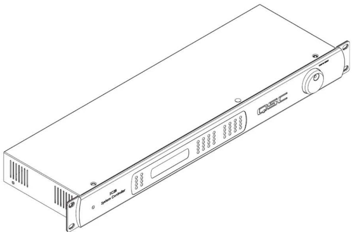
Two-Input, Eight-Output System Controller for QSC Loudspeakers
natural_image
Line drawing of a QSC System Controller device (no text or symbols on the main body)IMPORTANT SAFETY PRECAUTIONS & EXPLANATION OF SYMBOLS

The lightning flash with arrowhead symbol within an equilateral triangle is intended to alert the user to the presence of uninsulated “dangerous” voltage within the product’s enclosure that may be of sufficient magnitude to constitute a risk of electric shock to humans.

The exclamation point within an equilateral triangle is intended to alert the user to the presence of important operating and maintenance (servicing) instructions in this manual.

SAFEGAURDS
Electrical energy can perform many useful functions. This unit has been engineered and manufactured to assure your personal safety. Improper use can result in potential electrical shock or fire hazards. In order not to defeat the safeguards, observe the following instructions for its installation, use and servicing.

CAUTION: To reduce the risk of electric shock, do not remove the cover. No user-serviceable parts inside. Refer servicing to qualified service personnel.

WARNING: To prevent fire or electric shock, do not expose this equipment to rain or moisture.
1- Maximum operating ambient temperature is 40°C (104°F).
2- Never restrict airflow through the device vents. Please insure that the air intake and exhaust vents are unobstructed.
3- When installing equipment into rack, distribute the units evenly. Otherwise, hazardous conditions could be created by an uneven weight distribution.
4- Connect the unit only to a properly rated supply circuit. The SC28 is suitable for connection to 100 - 240 VAC, 50 - 60 hertz, with no special considerations other than the appropriate IEC power cord.
5- Reliable Earthing (Grounding) of rack-mounted equipment should be maintained.
FCC INTERFERENCE STATEMENT
NOTE: This equipment has been tested and found to comply with the limits for a class B digital device, pursuant to part 15 of the FCC rules. These limits are designed to provide reasonable protection against harmful interference in a residential installation. This equipment generates, uses, and can radiate radio frequency energy and if not installed and used in accordance to the instructions, may cause harmful interference to radio communications. However, there is no guarantee that interference will not occur in a particular installation. If this equipment does cause harmful interference to radio or television reception, which can be determined by switching the equipment off and on, the user is encouraged to try to correct the interference by one or more of the following measures:
- Reorient or relocate the receiving antenna.
- Increase the separation between the equipment and the receiver.
- Connect the equipment into an outlet on a circuit different from that to which the receiver is connected.
- Consult the dealer or an experienced radio or TV technician for help.
© Copyright 2007, OSC Audio Products, LLC OSC® is a registered trademark of OSC Audio Products, LLC "OSC" and the OSC logo are registered with the U.S. Patent and Trademark Office. All trademarks are the property of their respective owners.
Introduction
Congratulations and thank you for your purchase of this professional, loudspeaker signal processing product. To get the most from your investment, we recommend you review all the information provided in this User Manual.
The SC28 is a two-input, eight-output signal processor intended for use with QSC loudspeakers and QSC power amplifiers. The SC28 provides QSC system-specific signal processing for getting the highest performance and superior sound quality from QSC loudspeakers integrated with QSC amplifiers.
Two-channels of audio enter the SC28 via locking female XLR connectors. Digital audio conversion is 48 kHz, 24-bit, input and output with a very low noise floor and wide dynamic range. DSP is 32/40-bit floating point. Four channels of output for each of the two inputs are provided for controlling up to 3-way systems with subwoofers.
The SC28 provides excellent sound quality, durable construction and simple deployment. Amplifiers are matched to the drivers with active equalization and precise crossover control. Active loudspeaker protection extends the life of drivers. The SC28 solves many application challenges by greatly simplifying the configuration of multi-way loudspeaker systems. SC28 and QSC loudspeakers are the perfect solution for public performances, corporate events and private parties demanding flexible and excellent sounding system solutions.
SC28 Features
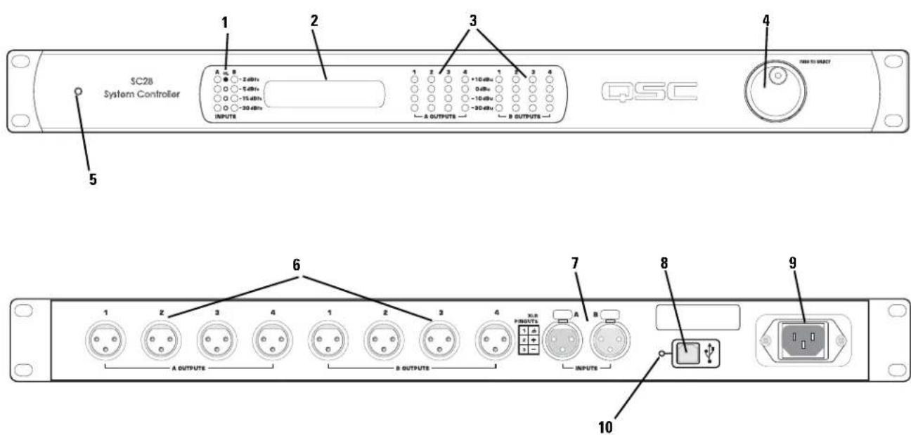
1- Input meters 6- Output connectors
2- LCD display 7- Input connectors
3- Output meters 8- USB port
4- Rotary encoder knob (press-to-select) 9- IEC inlet
5- Power LED 10- Firmware update mode select (recessed)
Unpacking
There are no special unpacking precautions. However, it is recommended you keep the original packing material for reuse in the rare event that service be required. If service is required and the original packing material is not available, ensure that the unit is adequately protected for shipment (strong box of appropriate size, sufficient packing material to prevent load-shifting or impact damage) or call QSC's Technical Services Department for packing material and a carton.
What is included in the carton:
Item Description Quantity
1 SC28 System Controller 1
2 Hardware Manual (this document) 1
3 IEC Power Cord 3 x #18 AWG, 2 meters 1
4 USB cable 1
5 System Wiring Reference Card(s) varies
Mounting
The SC28 can be used in or out of an equipment rack. Rack mounting is optional.
Rack Mounting
Rack mount the SC28 by supporting it from underneath while aligning the mounting holes with the threaded screw holes in the rails; install all four mounting screws and washers and tighten securely. Ensure use of all four mounting screws in order to minimize the chance of bending or distorting the rack mount ears. When installing equipment into rack, distribute the units evenly. Otherwise, hazardous conditions could be created by an uneven weight distribution.

Maximum operating ambient temperature is 40^ C ( 104^ F). Never restrict airflow through the device vents. Please insure that the air intake and exhaust vents are unobstructed.
Connections
AC Power Cord
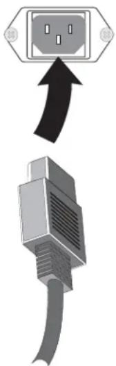
Insert the molded receptacle of the AC power cord into the AC power inlet on the rear panel of the SC28. Plug the AC line connector into the AC outlet. The power supply will accept 100-240 Volts AC, 50-60 Hertz. If a different type of IEC power cord is required than supplied with your SC28, contact QSC's Technical Services Department.

The correct AC line voltage is shown under the AC power inlet, on the rear panel. Connecting to the wrong line voltage may damage the amplifier or increase the risk of electric shock.
natural_image
Diagram showing a plug with internal socket connected to a cable, no text or symbols presentUSB Port
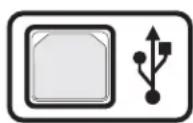
On the rear panel, there is a type "B" USB port. This port is for firmware updates and diagnostic functions. Refer to the Updating Firmware section of this manual for further information.
Audio Inputs
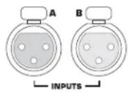
On the rear panel, there are two female XLR line-level inputs marked INPUTS below the connectors and designated A and B above the connectors. Connect the line-level analog audio inputs to these connectors. Input sensitivity can be selected from the Setup Menu; selections are 1.5 V_rms/6 dBu, 3 V_rms/12 dBu, 9 V_rms/21 dBu, or 18 V_rms/27 dBu. These values correspond to the maximum input signal level that can be applied to the inputs without clipping. The signal's source impedance should be less than 600 ohms.
We recommend balanced connections be used. Balanced connections will reduce AC hum and interference, especially with long cable runs. Unbalanced connections may be suitable for short cables. The input impedance is 11k ohm for balanced connections or 69k ohm for unbalanced connections.
Input connectors
Audio Outputs
There are two sets of line-level outputs on the rear panel grouped as A OUTPUTS and B OUTPUTS. Each group has four male XLR connectors numbered 1, 2, 3, and 4. They are "mapped" with the following general convention:
OUTPUT 1- Subwoofer Output
OUTPUT 2- Low Frequency 1 Output
OUTPUT 3- Low Frequency 2 Output
OUTPUT 4- High Frequency Output

There are two Low Frequency outputs (OUTPUT 2 and OUTPUT 3) to allow for low frequency shading requirements of line arrays when operated in triamp mode. If the shading network of the loudspeaker is used, OUTPUT 2 is not utilized and the amplifiers are operated in biamp mode.
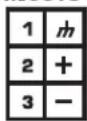
XLR Connector Pinout
Shown are the pinouts for the XLR connectors. Male connectors shown, pinout is the same for female connectors. We recommend balanced connections be used. Balanced connections will reduce AC hum and interference, especially with long cable runs. Unbalanced connections may be suitable for short cables. The input impedance is 11k ohm for balanced connections or 69k ohm for unbalanced connections.
Output connectors
Pinout label on rear panel
XLR PINOUTS
Balanced connection pinout
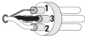
1= shield (ground)
3= minus (-)
2= plus (+)
Unbalanced connection pinout
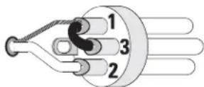
1= shield (ground)
3= jumper to pin 1
2= plus (+)
Use
General Information
Use of the SC28 involves adherence to the following to achieve proper operation:
1- Input sensitivity for the SC28 must be set to correspond with expected audio source levels.
2- Crossover type must be selected to correspond with amplifier and loudspeaker setup (Biamp or Triamp)
3- Subwoofer operation must be enabled or disabled. If enabled, subs can be configured as stereo or summed (mono) and sub gain can
be adjusted for more or fewer subwoofers than a typical system.
4- Delay times can be inserted for the subs and/or arrays.
5- Limiting can be selected for loudspeaker protection or clip limiting. Loudspeaker protection setting is recommended.
6- Each output of the SC28 must have the amplifier type/model selected and have the amplifier operating mode selected (stereo/bridge mono).
7- The "Amp Gain" value must be set to match the actual gain control settings of the amplifiers connected to the outputs. All amplifiers must be set to the same gain values.
8- Adherence to connector pinouts and wiring recommendations must be followed.
9- The SC28 "EQ Menu" selections can then be adjusted to compensate for array size, shape, and environmental factors.
Refer to the SC28 Menu Navigation, System Wiring Reference, and the loudspeaker's User Manuals for detailed information.
AC Mains
There is no AC power switch on the SC28. To connect AC Mains power to the SC28, insert the IEC molded line cord plug into the IEC receptacle on the rear panel and plug the AC line cord plug into a properly operating AC outlet. To disconnect the SC28 from the AC Mains, unplug the AC line cord plug from the AC Mains outlet.
Amplifier Setup
The OSC amplifiers connected to the SC28 must have their power switches in the "on" position. For initial testing, use the lowest useful gain setting until the system is operating as expected. After the system setup has been verified and tested, gain settings may be adjusted as required.
All amplifiers should have their Gain controls set to identical values. This applies to all amp channels, not just channels on one amp.

IMPORTANT! Amp gain control values must be entered in the amplifier setup menu for proper operation.
Updating Firmware
If a firmware update is required, please visit the QSC website and navigate to the SC28 Firmware Updater page. Download and install the SC28 Firmware Updater software and follow the instructions provided with the software. The USB port is used for the update and a cable is supplied with the SC28.
Security Features
The 4-digit passcode is set and enabled via passcode screens in the SC28's Utility menu. When the passcode is enabled, no menu access is allowed without the passcode. After 10 minutes of inactivity, the display will automatically revert to the Startup menu and will prompt the user for the passcode (if enabled). Resetting the passcode: Push in on the rotary encoder knob while the power is turned on (IEC linecord inserted into IEC inlet).
Channel Link
Channel Linking may be enabled/disabled via the channel link screen in the Utility menu. When Channel Link is enabled (Linked) some A/B controls become linked and are controlled via a single front-panel screen. When channel Link is disabled (Independent) these controls are adjusted independently via separate front-panel screens. When changing the Channel Link form Independent to Linked, channel A's parameters overwrite the channel B's.
Left/Right Controls that may be linked:
- Sub and Array delays
- Parameters of all user-adjustable filters
- Input mute and sensitivity
- Output mutes
- Sub gain
LED Indicators
LED metering of both input and output are provided. Input metering is indicated as relative to 0 dBfs (digital clipping of the input signal) and output metering is indicated in actual output voltage levels in dBu. Meters are peak-reading and updated every 50 milliseconds.
The lower input metering LEDs will remain illuminated as successively higher levels are indicated. When 0 dbfs is reached, ONLY the upper red LED will illuminate (lower LEDs will extinguish). If 0 dBfs is indicated often, reduce input signal level to the SC28. This will reduce possibly audible distortion caused by clipping the digital input of the SC28.
The output meters indicate the actual output voltage level in dBu (0dBu=0.775Vrms). Most QSC amplifiers clip/limit at about +4 dBu input level.
LCD Display and Control (Rotary Encoder)
The SC28 has a 2 line X 16 character LCD display. The display and the push-to-select rotary encoder knob provide data access and editing capability. The rotary select/accept knob is active for most displayed items allowing you to scroll through choices by rotating the control, and accepting choices (entering) by pushing in on the control.
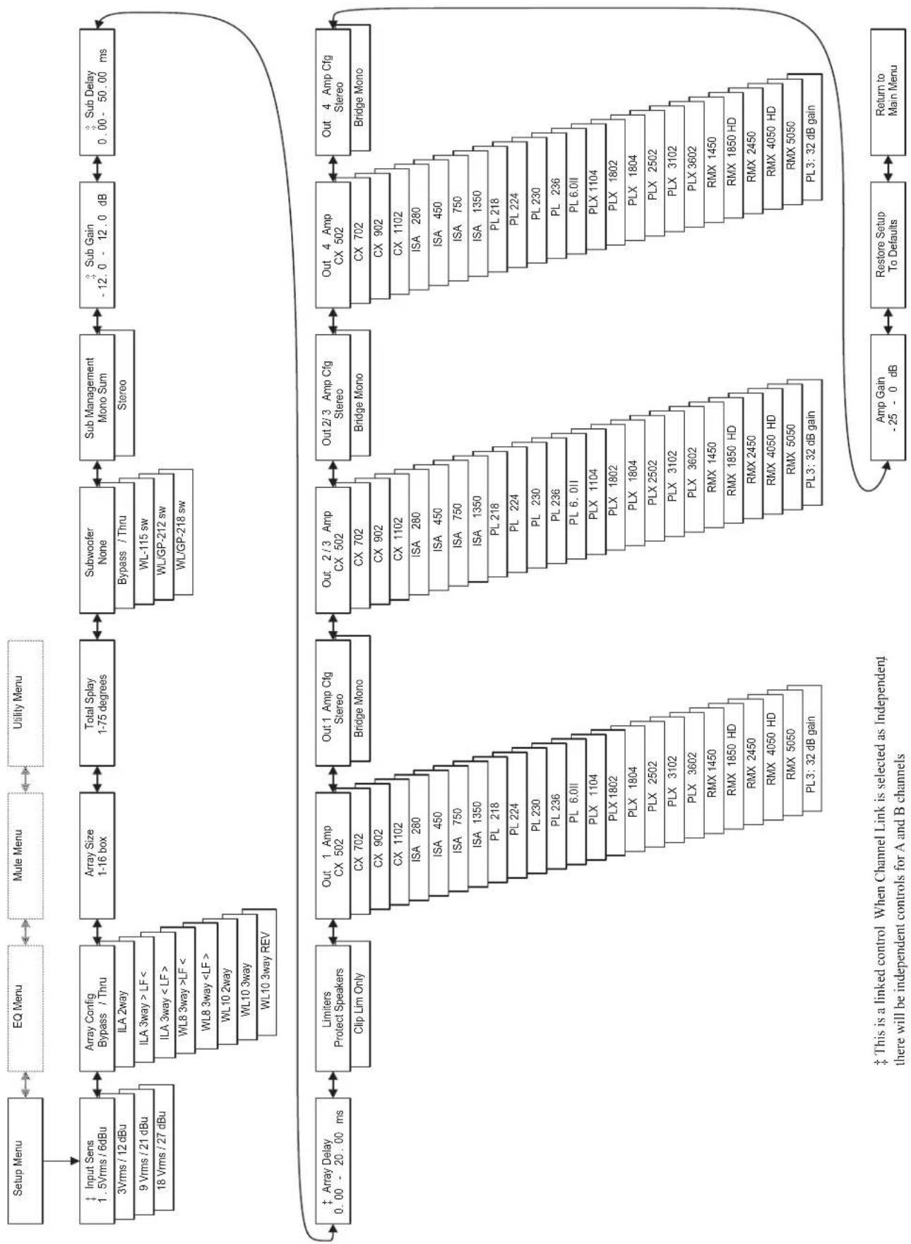
The accessible menus and sub menus may appear differently than example shown. Software updates may occasionally improve the interface. On the following pages are shown the basic navigation flow for the SC28 menu system; Setup, EQ, Gain, and Utility.
Notes:
When editing parameters such as Gain or Filter Frequency, turning the knob more quickly (i.e. "spinning") will accelerate the parameter's change.
LCD Icon key:

Loudspeaker protection/clip limiting is active

Turning the knob to the right will increment the current selection

Turning the knob to the left will decrement the current selection

Pressing knob will enter sub-menu or allow the current selection to be edited
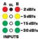
Input metering for the SC28- Note digital clipping will be indicated by ONLY the top red LED being illuminated.
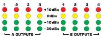
Output metering for the SC28-Meters indicate actual voltage level in dBu for each output. +4 dBu is maximum input level for most QSC amplifiers.
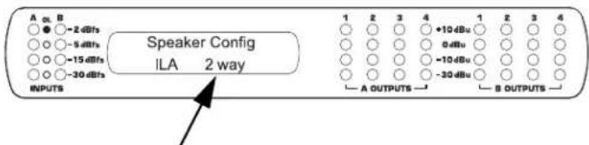
Control knob (rotary encoder)-Adjustable parameters can be changed by rotating the knob and accepted/selected by pushing in on the knob.
LCD Navigation Map- Setup
flowchart
graph TD
    A["Setup Menu"] --> B["EQ Menu"]
    B --> C["Mule Menu"]
    C --> D["Utility Menu"]
    D --> E["Input Sens 1.5Vrms / 6dBu"]
    E --> F["Array Config Bypass / Thru"]
    F --> G["Array Size 1-16 box"]
    G --> H["Total Splay 1-75 degrees"]
    H --> I["Subwoofer None"]
    I --> J["Sub Management Mono Sum Stereo"]
    J --> K["Sub Gain -12.0 - 12.0 dB"]
    K --> L["Sub Delay 0.00 - 50.00 ms"]

    M["Array Delay 0.00 - 20.00 ms"] --> N["Limiters Protect Speakers Clip Lim Only"]
    N --> O["Out 1 Amp CX 502 CX 702 CX 902 CX 1102 ISA 280 ISA 450 ISA 750 ISA 1350 PL 218 PL 224 PL 230 PL 236 PL 6.0II PLX 1104 PLX 1802 PLX 1804 PLX 2502 PLX 3102 PLX 3602 RMX 1450 RMX 1850 HD RMX 2450 RMX 4050 HD RMX 5050 PL3: 32 dB gain"]

    O --> P["Out 1 Amp Cfg Stereo Bridge Mono"]
    P --> Q["Out 2/3 Amp CX 502 CX 702 CX 902 CX 1102 ISA 280 ISA 450 ISA 750 ISA 1350 PL 218 PL 224 PL 230 PL 236 PL 6.0II PLX 1104 PLX 1802 PLX 1804 PLX 2502 PLX X 3102 PLX X 3602 RMX 1450 RMX 1850 HD RMX 2450 RMX 4050 HD RMX 5050 PL3: 32 dB gain"]

    Q --> R["Out 4 Amp CX 502 CX 702 CX 902 CX 1102 ISA 280 ISA 450 ISA 750 ISA 1350 PL X 1802 PLX 1804 PLX X 3102 PLX X 3602 RMX 1450 RMX 1850 HD RMX 2450 RMX 4050 HD RMX 5050 PL3: 32 dB gain"]

    R --> S["Out 4 Amp Cfg Stereo Bridge Mono"]
    S --> T["Amp Gain -25 - 0 dB"]
    T --> U["Restore Setup To Defaults"]
    U --> V["Return to Main Menu"]

    style A fill:#f9f,stroke:#333
    style B fill:#f9f,stroke:#333
    style C fill:#f9f,stroke:#333
    style D fill:#f9f,stroke:#333
    style E fill:#f9f,stroke:#333
    style F fill:#f9f,stroke:#333
    style G fill:#f9f,stroke:#333
    style H fill:#f9f,stroke:#333
    style I fill:#f9f,stroke:#333
    style J fill:#f9f,stroke:#333
    style K fill:#f9f,stroke:#333
    style L fill:#f9f,stroke:#333
    style M fill:#f9f,stroke:#333
    style N fill:#f9f,stroke:#333
    style O fill:#f9f,stroke:#333
    style P fill:#f9f,stroke:#333
    style Q fill:#f9f,stroke:#333
    style R fill:#f9f,stroke:#333
    style S fill:#f9f,stroke:#333
    style T fill:#f9f,stroke:#333
    style U fill:#f9f,stroke:#333
    style V fill:#f9f,stroke:#333

    subgraph Control
        W["Input Sens 1.5Vrms / 6dBu"]
        X["Array Config Bypass / Thru"]
        Y["ILA 2way"]
        Z["ILA 3way > LF <"]
        AA["ILA 3way < LF >"]
        AB["WL8 3way >LF <"]
        AC["WL8 3way < LF >"]
        AD["WL10 2way"]
        AE["WL10 3way"]
        AF["WL10 3way REV"]
    end

    subgraph Secondary Control
        G
        I
        J
        K
        L
        M
        N
        O
        P
        Q
        R
        S
        T
        U
        V
        W
        X
        Y
        Z
        AA
        AB
        AC
        AD
        AE
        AF
        AG
        AH
    end

    subgraph Channel Link Control
        N
        O
        P
        Q
        R
        S
        T
        U
        V
        W
        X
        Y
        Z
        AA
        AB
        AC
        AD
        AE
        AF
        AG
        AH
        AI
    end

    subgraph Independent Control
        N
        O
        P
        Q
        R
        S
        T
        U
        V
        W
        X
        Y
        Z
        AA
        AB
        AC
        AD
        AE
        AF
        AG
        AH
        AI
    end

    subgraph Channel Links Control
        N
        O
        P
        Q
        R
        S
        T
        U
        V
        W
        X
        Y
        Z
        AA
        AB
        AC
        AD
        AE
        AF
        AG
        AH
        AI
    end

    subgraph Channel Links & Independent Controls (A and B channels)
            W["Input Sens 1.5Vrms / 6dBu"]
            X["Array Config Bypass / Thru"]
            Y["ILA 2way"]
            Z["ILA 3way > LF <"]
            AA["ILA 3way < LF >"]
            AB["WL8 3way >LF <"]
            AC["WL8 3way < LF >"]
            AD["WL10 2way"]
            AE["WL10 3way"]
            AF["WL10 3way REV"]
    end

    subgraph Channel Links & Independent Controls & Independent Controls (A and B channels)
            N["Input Sens 1.5Vrms / 6dBu"]
            X["Array Config Bypass / Thru"]
            Y["ILA 2way"]
            Z["ILA 3way > LF <"]
            AA["ILA 3way < LF >"]
            AB["WL8 3way >LF <"]
            AC["WL8 3way < LF >"]
            AD["WL10 2way"]
            AE["WL10.3way"]
            AF["WL10.3way REV"]
    end

    subgraph Channel Links & Independent Controls & Independent Controls (A and B channels)
            N["Input Sens 1.5Vrms / 6dBu"]
            X["Array Config Bypass / Thru"]
            Y["ILA 2way"]
            Z["ILA 3way > LF <"]
            AA["ILA 3way < LF >"]
            AB["WL8 3way >LF <"]
                    end

    subgraph Channel Links & Independent Controls & Independent Controls (A and B channels)
            N["Input Sens 1.5Vrms / 6dBu"]
            X["Array Config Bypass / Thru"]
            Y["ILA 2way"]
            Z["ILA 3way > LF <"]
            AA["ILA 3way < LF >"]
            AB["WL8 3way >LF <"]
                    end

    sub-Channel Links Control:
    N --> O --> P --> Q --> R --> S --> T --> U --> V --> W --> X --> Y --> Z --> AA --> AB --> AC --> AD --> AE --> AF --> AG --> AH --> AI --> AJ --> AK --> AL --> AM --> AN --> AO --> AP --> AQ --> AQ --> AR --> AS --> AT --> AU --> AV --> AW --> AX --> AX --> AY --> AZ --> BA --> BB --> BC --> BD --> BE --> BF --> BG --> BH --> BH --> BI --> BJ --> BK --> BL --> BN --> BN --> BO --> BP --> BPb --> BPc --> BPd --> BPdB --> BPdBb & BPdBb & BPdBb & BPdBb & BPdBb & BPdBb & BPdBb & BPdBb & BPdBb & BPdBb & BPdBb & BPdBb & BPdBb & BPdBb & BPdBb & BPdBb & BPdBb & BPdBb & BPdBb & BPdBb & BPdBb &
    end

    sub-Channel Links Control:
    N --> O --> P --> Q --> R --> S --> T --> U --> V --> W --> X --> Y --> Z --> AA --> AB --> AC --> AD --> AE --> AF --> AG --> AH --> AI --> AJ --> AK --> AL --> AJb & AK & AJb & AJb & AJb & AJb & AJb & AJb & AJb & AJb & AJb & AJb & AJb & AJb & AJb & AJb & AJb & AJb & AJb & AJb & AJb & AJb & AJb & AJb & AJb & AJb & AJb & AJb & AJb & AJb & AJb & AJb & AJb & AJb & AJb & AJb &
    end

    sub-Channel Links Control:
    N --> O --> P --> Q --> R --> S --> T --> U --> V --> W --> X --> Y --> Z --> AA --> AB --> AC --> AD --> AE --> AF --> AG --> AH --> AI --> AJ --> AK --> AL --> AJb & AK & AJb & AJb & AJb & AJb & AJb & AJb & AJb & AJb & AJb & AJb & AJ b & AJ b & AJ b & AJ b & AJ b & AJ b & AJ b & AJ b & AJ b & AJ b & AJ b & AJ b & AJ b & AJ b & AJ b & AJ b & AJ b & AJ b & AJ b & AJ b & AJ b & AJ b & AJ b & AJ b & AJ b & AJ b & AJ b & AJ b & AJ b & AJ b & AJ b & AJ b & AJ b & AJ b |
This is a linked control When Channel Link is selected as Independent
there will be independent controls for A and B channels
LCD Navigation Map- Equalization
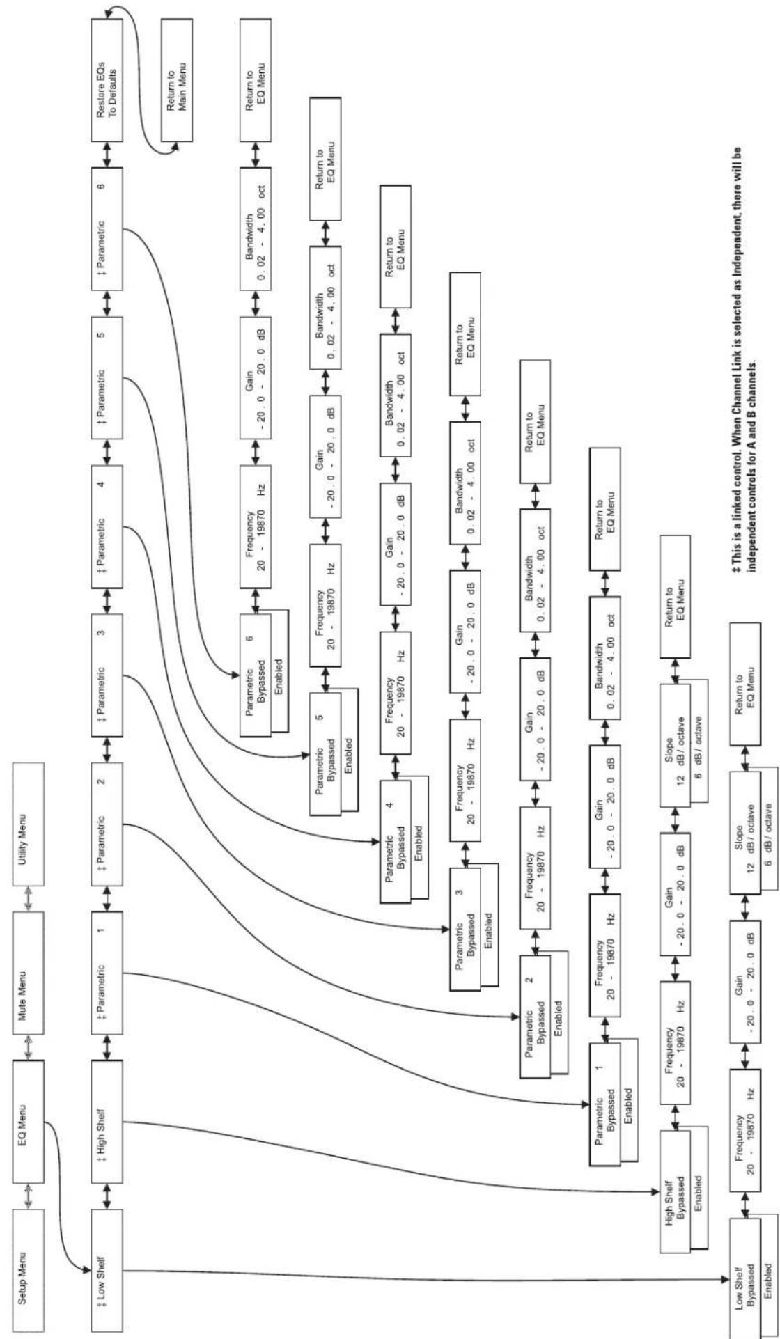
flowchart
graph TD
    A["Setup Menu"] --> B["EQ Menu"]
    B --> C["Mute Menu"]
    C --> D["Utility Menu"]
    D --> E["Low Shelf"]
    E --> F["High Shelf Bypassed"]
    F --> G["Low Shelf Bypassed"]
    G --> H["Energy Levels"]

    I["Setup Menu"] --> J["EQ Menu"]
    J --> K["Mute Menu"]
    K --> L["Utility Menu"]

    M["Low Shelf"] --> N["High Shelf"]
    N --> O["Low Shelf Bypassed"]
    O --> P["Energy Levels"]

    Q["Low Shelf"] --> R["High Shelf Bypassed"]
    R --> S["Low Shelf Bypassed"]

    T["Low Shelf"] --> U["High Shelf Bypassed"]
    U --> V["Low Shelf Bypassed"]

    W["Low Shelf"] --> X["High Shelf Bypassed"]
    X --> Y["Low Shelf Bypassed"]

    Z["Low Shelf"] --> AA["High Shelf Bypassed"]
    AA --> AB["Low Shelf Bypassed"]

    AC["Low Shelf"] --> AD["High Shelf Bypassed"]
    AD --> AE["Low Shelf Bypassed"]

    AF["Low Shelf"] --> AG["High Shelf Bypassed"]
    AG --> AH["Low Shelf Bypassed"]

    AI["Low Shelf"] --> AJ["High Shelf Bypassed"]
    AJ --> AK["Low Shelf Bypassed"]

    AL["Low Shelf"] --> AM["High Shelf Bypassed"]
    AM --> AN["Low Shelf Bypassed"]

    AO["Low Shelf"] --> AP["High Shelf Bypassed"]
    AP --> AQ["Low Shelf Bypassed"]

    AR["Low Shelf"] --> AS["High Shelf Bypassed"]
    AS --> AT["Low Shelf Bypassed"]

    AU["Low Shelf"] --> AV["High Shelf Bypassed"]
    AV --> AW["Low Shelf Bypassed"]

    AX["Low Shelf"] --> AY["High Shelf Bypassed"]
    AY --> AZ["Low Shelf Bypassed"]

    BA["Low Shelf"] --> BB["High Shelf Bypassed"]
    BB --> BC["Low Shelf Bypassed"]

    BD["Low Shelf"] --> BE["High Shelf Bypassed"]
    BE --> BF["Low Shelf Bypassed"]

    BG["Low Shelf"] --> BH["High Shelf Bypassed"]
    BH --> BI["Low Shelf Bypassed"]

    BJ["Low Shelf"] --> BK["High Shelf Bypassed"]
    BK --> BL["Low Shelf Bypassed"]

    BM["Low Shelf"] --> BN["High Shelf Bypassed"]
    BN --> BO["Low Shelf Bypassed"]

    BP["Low Shelf"] --> BQ["High Shelf Bypassed"]
    BQ --> BR["Low Shelf Bypassed"]

    BS["Low Shelf"] --> BT["High Shelf Bypassed"]
    BT --> BU["Low Shelf Bypassed"]

    BV["Low Shelf"] --> BW["High Shelf Bypassed"]
    BW --> BX["Low Shelf Bypassed"]

    BY["Low Shelf"] --> BZ["High Shelf Bypassed"]
    BZ --> CA["Low Shelf Bypassed"]

    CB["Low Shelf"] --> CC["High Shelf Bypassed"]
    CC --> CD["Low Shelf Bypassed"]

    CE["Low Shelf"] --> CF["High Shelf Bypassed"]
    CF --> CG["Low Shelf Bypassed"]

    CH["Low Shelf"] --> CI["High Shelf Bypassed"]
    CI --> CJ["Low Shelf Bypassed"]

    CK["Low Shelf"] --> CL["High Shelf Bypassed"]
    CL --> CD
    CM["Low Shelf"] --> CN["High Shelf Bypassed"]
    CN --> CO["Low Shelf Bypassed"]

    CP["Low Shelf"] --> CDA["High Shelf Bypassed"]
    CDA --> CE
    DD["Low Shelf"] --> DJA
    DJA --> CE
LCD Navigation Map- Gain
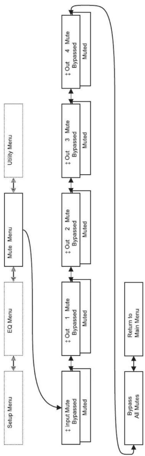
flowchart
graph TD
    A["Setup Menu"] --> B["EQ Menu"]
    B --> C["Mute Menu"]
    C --> D["Utility Menu"]
    D --> E["Input Mute Bypassed\nMuted"]
    E --> F["Out 1 Mute Bypassed\nMuted"]
    F --> G["Out 2 Mute Bypassed\nMuted"]
    G --> H["Out 3 Mute Bypassed\nMuted"]
    H --> I["Out 4 Mute Bypassed\nMuted"]
    I --> J["Bypass All Mutes"]
    J --> K["Return to Main Menu"]
    K --> E
‡ This is a linked control. When Channel Link is selected as Independent, there will be independent controls for A and B channels.
LCD Navigation Map- Utility

flowchart
graph TD
    A["Setup Menu"] --> B["EQ Menu"]
    B --> C["Mute Menu"]
    C --> D["Utility Menu"]
    D --> E["Channel Link Linked\nIndependent"]
    E --> F["Edit Passcode 0000"]
    F --> G["Passcode Disabled\nEnabled"]
    G --> H["LCD Contrast 0 - 100 %"]
    H --> I["Version 1.00 . xxxx"]
    I --> J["Return to Main Menu"]
    J --> D
Signal Flow
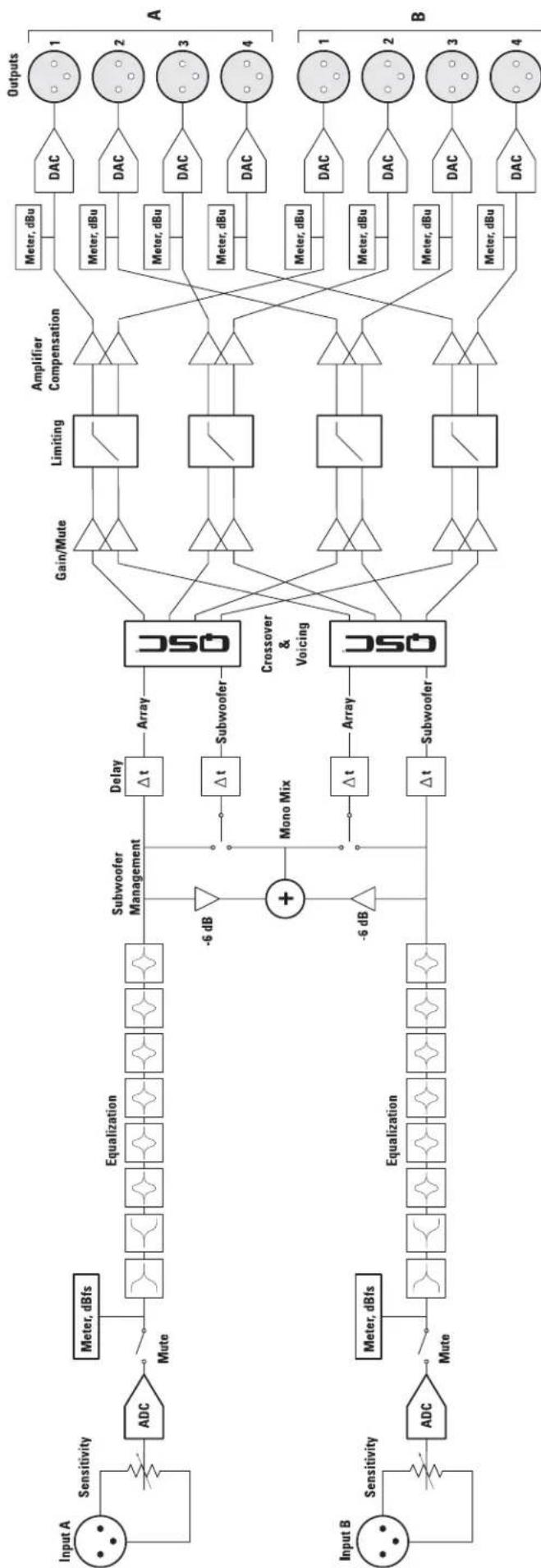
flowchart
graph LR
    subgraph_Input_A["Input A"]
        A1["Sensitivity"] --> A2["ADC"]
        A2 --> A3["Mute"]
        A3 --> A4["Equalization"]
        A4 --> A5["Subwoofer Management"]
        A5 --> A6["Delay Δt"]
        A6 --> A7["Array"]
        A7 --> A8["+"]
        A8 --> A9["Mono Mix"]
        A9 --> A10["Δt"]
        A10 --> A11["Subwoofer"]
        A11 --> A12["ΣCrossover & Voicing"]
    end

    subgraph_Input_B["Input B"]
        B1["Sensitivity"] --> B2["ADC"]
        B2 --> B3["Mute"]
        B3 --> B4["Equalization"]
        B4 --> B5["Subwoofer"]
        B5 --> B6["+"]
        B6 --> B7["-6 dB"]
        B7 --> B8["Δt"]
        B8 --> B9["Array"]
        B9 --> B10["ΣCrossover & Voicing"]

    A7 --> C1["Gain/Mute"]
    C1 --> C2["Limiting"]
    C2 --> C3["Amplifier Compensation"]
    C3 --> C4["Meter, dBu"]
    C4 --> C5["DAC"]
    C5 --> C6["Outputs 1"]
    C5 --> C7["Meter, dBu"]
    C7 --> C8["DAC"]
    C8 --> C9["Output 2"]
    C8 --> C10["Meter, dBu"]
    C10 --> C11["DAC"]
    C11 --> C12["Output 3"]
    C11 --> C13["Meter, dBu"]
    C13 --> C14["DAC"]
    C14 --> C15["Output 4"]

    subgraph_Output_A["A"]
        D1["Sensitivity"] --> E1["Meter, dBfs"]
        E1 --> E2["Mute"]
        E2 --> E3["Equalization"]
        E3 --> E4["Subwoofer Management"]
        E4 --> E5["Delay Δt"]
        E5 --> E6["Array"]
        E6 --> E7["-6 dB"]
        E7 --> E8["+"]
        E8 --> E9["-6 dB"]
        E9 --> E10["Δt Subwoofer"]

    subgraph_Output_B["B"]
        F1["Sensitivity"] --> G1["Meter, dBfs"]
        G1 --> G2["Mute"]
        G2 --> G3["Equalization"]
        G3 --> G4["Subwoofer Management"]
        G4 --> G5["Δt Subwoofer"]

    subgraph Output_C
        H1["Sensitivity"] --> I1["DAC"]
        I1 --> I2["DAC"]
        I2 --> I3["DAC"]
        I3 --> I4["DAC"]
        I4 --> I5["DAC"]
        I5 --> I6["DAC"]
        I6 --> I7["DAC"]
        I7 --> I8["DAC"]
        I8 --> I9["DAC"]
    end
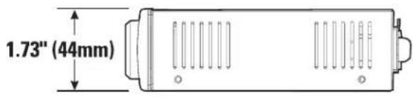
Dimensions

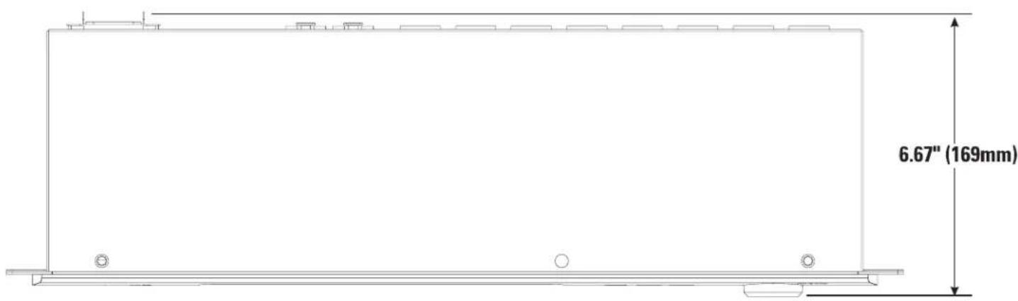
Preliminary Specification
Dynamic Range (AES-17, -60 dB Method, all sensitivities)
unweighted >104 dB
A weighted >107 dB
Distortion (AES-17, 20 Hz-20 kHz, all sensitivities)
+4 dBu <0.006% THD+N
2 dB below clip (max) <0.006% THD+N
Crosstalk (20 Hz - 20k Hz)
inter-channel (max) >75 dB
Input Impedance
Balanced (nominal) 11k ohms
Unbalanced (nominal) 69k ohms
Common-Mode Rejection
20 Hz - 20k Hz (min) >75 dB
20 Hz - 20k Hz (typ) >80 dB
Input Sensitivities 1.5 V
rms/6 dBu, 3 Vrms/12 dBu, 9 Vrms/21 dBu, or 18 Vrms/27 dBu
Audio Converters 24-bit, 48 kHz, in and out
Digital Processing 32/40-bit floating-point
Mute infinite attenuation
Throughput Delay 1.4125 milliseconds
Program Inputs 2
Connector Type
Type
Grounding
Pinout
XLR female, locking
Electrically balanced
All shield terminals connected to chassis
1: GND
2: +
3: -
Program Outputs
Connector Type
Type
Grounding
Pinout
8
XLR male
Electrically balanced
All shield terminals connected to chassis
1: GND
2: +
3:
Controls
Rotary encoder knob with push-to-select function
Indicators
Power
LCD Data Display
Input/Output Meters
Blue, front panel
2 line x 16 character, backlit, front panel
Green, Yellow, Red, front panel
Specifications are subject to change without notice.
Preliminary Specification
USB Port USB type "B"
USB Cable 1.5 meters long, USB 1.1 compliant
AC Power Requirements 100-240 VAC, 50-60 Hz, no user adjustment required
AC Power Connection IEC-type inlet
AC Power Cord 2 meters long, #18AWG
Specifications are subject to change without notice.
Warranty (USA only; other countries, see your dealer or distributor)
Disclaimer
QSC Audio Products, LLC is not liable for any damage to amplifiers or any other equipment that is caused by negligence or improper installation and/or use of this loudspeaker product.
QSC Audio Products 3 Year Limited Warranty
QSC Audio Products, LLC ("QSC") guarantees its products to be free from defective material and / or workmanship for a period of three (3) years from date of sale, and will replace defective parts and repair malfunctioning products under this warranty when the defect occurs under normal installation and use - provided the unit is returned to our factory or one of our authorized service stations via prepaid transportation with a copy of proof of purchase (i.e., sales receipt). This warranty provides that the examination of the return product must indicate, in our judgment, a manufacturing defect. This warranty does not extend to any product which has been subjected to misuse, neglect, accident, improper installation, or where the date code has been removed or defaced. QSC shall not be liable for incidental and/or consequential damages. This warranty gives you specific legal rights. This limited warranty is freely transferable during the term of the warranty period.
Customer may have additional rights, which vary from state to state.
In the event that this product was manufactured for export and sale outside of the United States or its territories, then this limited warranty shall not apply. Removal of the serial number on this product, or purchase of this product from an unauthorized dealer, will void this limited warranty.
Periodically, this warranty is updated. To obtain the most recent version of QSC's warranty statement, please visit www.qscaudio.com.
Contact us at 800-854-4079 or visit our website at www.qscaudio.com
1675 MacArthur Blvd., Costa Mesa, CA, 92626 USA
Main Number (714) 754-6175 or toll free (USA only) (800) 854-4079
Customer Service(714) 957-7150 or toll free (USA only) (800) 772-2834
- Loudspeaker Signal Processing Products User Manual
- IMPORTANT SAFETY PRECAUTIONS & EXPLANATION OF SYMBOLS
- SAFEGAURDS
- FCC INTERFERENCE STATEMENT
- Introduction
- Unpacking
- Item Description Quantity
- Mounting
- Rack Mounting
- Connections
- AC Power Cord
- USB Port
- Audio Inputs
- Audio Outputs
- XLR Connector Pinout
- Use
- General Information
- AC Mains
- Amplifier Setup
- Updating Firmware
- Security Features
- Channel Link
- Left/Right Controls that may be linked:
- LED Indicators
- LCD Display and Control (Rotary Encoder)
- Notes:
- LCD Icon key:
- Preliminary Specification
- Warranty (USA only; other countries, see your dealer or distributor)
- Disclaimer
- QSC Audio Products 3 Year Limited Warranty
Brand : QSC
Model : SC28
Category : Processor