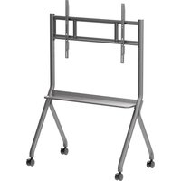
MC086C - Microwave HISENSE - Free user manual and instructions
Find the device manual for free MC086C HISENSE in PDF.


| Product Type | Mobile Cart for Interactive Displays |
| Compatible Screen Sizes | 55 to 86 inches |
| Maximum Load Capacity | 100 kg (220 lbs) |
| Materials | Steel frame with plastic components |
| Dimensions (Approx.) | 600 x 400 x 1500 mm (23.6 x 15.7 x 59 in) |
| Weight | 30 kg (66 lbs) |
| Wheel Type | Lockable casters (4 pcs) |
| Assembly Required | Yes, with included hardware and instructions |
| Included Hardware | Hexagon head screws M8x25 (14 pcs), M12 gasket (4 pcs) |
| Wall Hanger Bracket Holes | 6 positions; recommendation chart for 55", 65-70", 75-86" |
| Safety Features | Brake on wheels, safety screw lock, requires 2 professionals for wall hanging |
| Installation Steps | 6-step assembly including wheel installation, bracket attachment, tray assembly |
| Additional Accessories | Adjustable wrench (not included) |
| Repairability | Replacement parts available via customer support |
| Warranty | Standard manufacturer warranty (contact support) |
Frequently Asked Questions - MC086C HISENSE
User questions about MC086C HISENSE
0 question about this device. Answer the ones you know or ask your own.
Ask a new question about this device
Download the instructions for your Microwave in PDF format for free! Find your manual MC086C - HISENSE and take your electronic device back in hand. On this page are published all the documents necessary for the use of your device. MC086C by HISENSE.
USER MANUAL MC086C HISENSE
natural_image
Line drawing of a four-legged table with wheels, no text or symbols presentMOBILE CART FOR HISENSE INTERACTIVE DISPLAYS
To ensure correct and safe use, please read this manual carefully before installation.
This model is suit for 55-86 inch smart board.
The maximum load of this support is 100KG.
Materials List
● Materials List
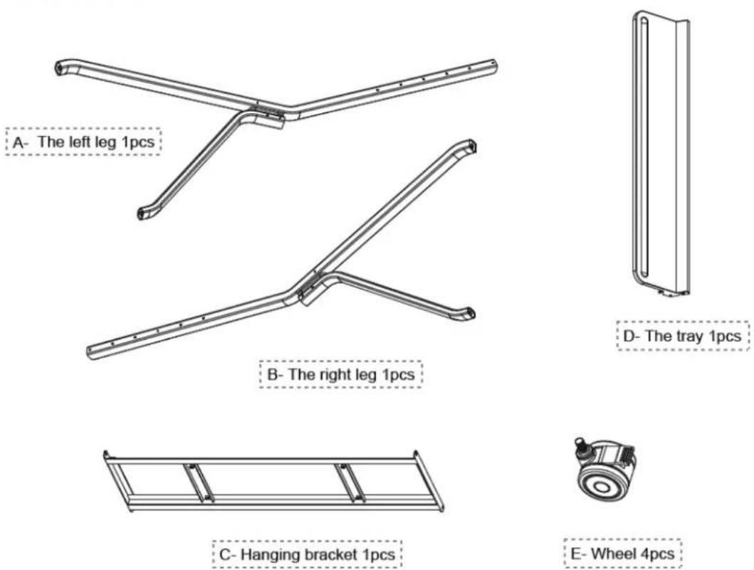
Other accessories (unit: mm):
| 1: Hexagon head screw | M8×25 14pcs |  |
| 2: M12 gasket | 4pcs |  |
| Prepare for yourself | 1pcs |  |
| Prepare for yourself | 1pcs |  |
Step 1: Adjust the wheel to the brake position and screw it into the leg.(Refer to figure 1):

FIG 1
Step 2: Attach the wall hanger bracket lock to one end of the leg.(Refer to figure 2)

Step 3: Attach another leg lock to the other end of the wall hanger bracket. (Refer to figure 3)

natural_image
Technical line drawing of a mechanical frame with a tool and directional arrow, labeled 'FIG 3' (no text or symbols on the diagram itself)Step 4: Assemble the tray between the two columns.(Refer to figure 4)
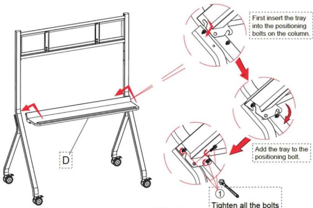
FIG 4
Step 5: Lock the wall hangers on the whole machine according to the actual requirements of the whole machine.(Refer to figure 5)

natural_image
Technical line drawing of a mechanical assembly with two tool holders and a handle, no text or symbols presentFIG 5
Step 6: Hang the assembled whole machine on the wall hanging bracket and lock the safety screw of the wall hanging bar.(Refer to figure 6)
Make sure the brakes are locked. At least 2 professionals are required to complete this step.

natural_image
Diagram showing a hand operating a cable with a red-handled tool, and a separate view of a monitor mounted on a tripod stand (no text or symbols present)FIG 6
Remark: In some cases, the built-in hangers of the whole machine cannot be effectively matched to the foot rack, so the hangers need to be matched with the wall hangers. The fitting process is as follows
- Lock the wall hanger panel on the wall hanger bracket

- Hang the whole machine on the wall and lock the safety bolt

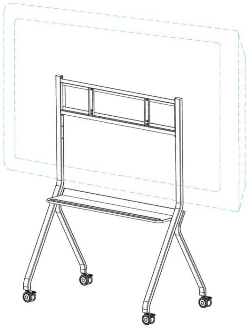
Step10: After the assembly effect, refer to the below picture.
natural_image
Line drawing of a four-legged table with wheels and a backrest (no text or symbols)Hisense
Commercial Display
Hisense Commercial Displays
Tel: +44 (0)115 8248811
Email: sales@hisense-b2b.com
Web: www.hisense-b2b.com

Brand : HISENSE
Model : MC086C
Category : Microwave