
DHRCP - Uncategorized DANFOSS - Free user manual and instructions
Find the device manual for free DHRCP DANFOSS in PDF.


| Product Type | Hydraulic Foot Pedal Remote Control (HRC) |
| Series | D-HRC (Danfoss Hydraulic Remote Control) |
| Model Variants | DHRCP-Double, DHRCP-Single, DHRCP-Push only, DHRCP-Mini |
| Max Inlet Pressure | 70 bar (Double/Single/Mini), 50 bar (Push only) |
| Max Back Pressure | 3 bar |
| Rated Flow | 20 LPM (Double/Mini), 10 LPM (Single/Push only) |
| Output Pressure Range | 0 to 30 bar |
| Fluid Type | Mineral oil |
| Fluid Temperature Range | -20°C to 90°C |
| Ambient Temperature Range | -40°C to 60°C |
| Fluid Viscosity | 12 to 400 mm²/s |
| Max Fluid Contamination Level | 18/16/13 per ISO 4406 |
| Operation Angle Range | 12° to 30° (depending on variant) |
| Operation Torque Range | 0.16 to 6.99 Nm (depending on variant) |
| Lifecycle | Greater than 1,000,000 cycles |
| Weight (Foot Plate) | 1 to 4.4 kg (depending on variant) |
| Weight (Body Assembly) | 0.7 to 9 kg (depending on variant) |
| Total Weight | 0.7 to 13.4 kg (depending on variant) |
| Electric Push Button Rating | AC 125V 5A (IP40) or AC 125V 3A (IP69K/IP67) |
| Electric Roller Rating | Signal 5V (IP40 or IP69K) |
| FNR/Fr Switch Rating | AC 125V 3A (IP40) |
| Electric Detent Voltage | DC 12V or 24V |
| Body Material Options | Cast iron or aluminum alloy |
| Port Options | BSPP G1/4 or UNF 9/16 O-ring sealing |
Frequently Asked Questions - DHRCP DANFOSS
User questions about DHRCP DANFOSS
0 question about this device. Answer the ones you know or ask your own.
Ask a new question about this device
Download the instructions for your Uncategorized in PDF format for free! Find your manual DHRCP - DANFOSS and take your electronic device back in hand. On this page are published all the documents necessary for the use of your device. DHRCP by DANFOSS.
USER MANUAL DHRCP DANFOSS
Technical Information
DHRCP
Hydraulic Foot Pedals
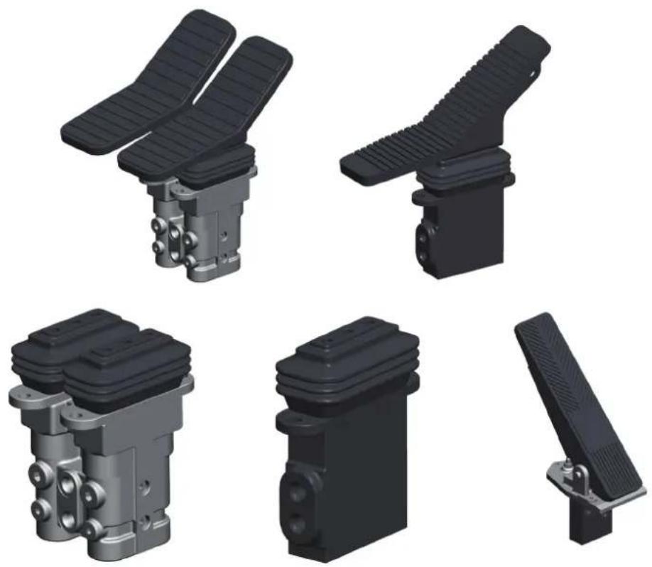
DHRCP is part of D-HRC series.
D-HRC means Danfoss Hydraulic Remote Control valves which include:
DHRCJ — — Hydraulic Joystick
DHRCD — — Hydraulic Pilot Sectional Valve
DHRCP — — Hydraulic Foot Pedals
Excavator
Crane
Loader
AWP
Forklift
Drilling machine
Special vehicles
Contents
General Description....3
General Specification....4
Configuration....5
Options 6
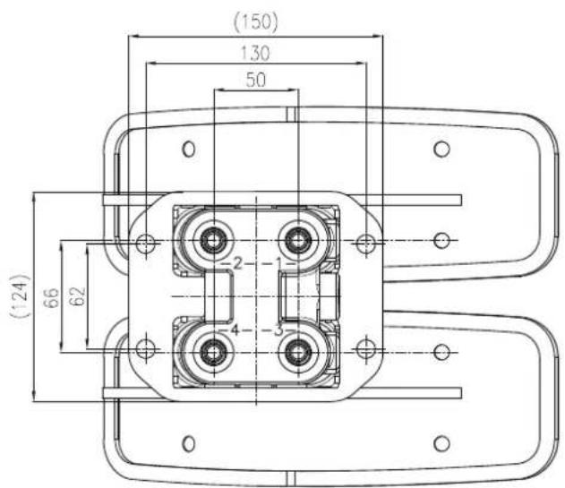
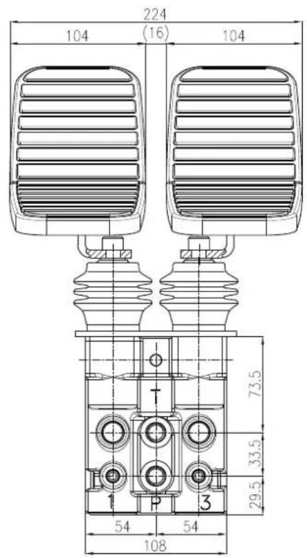
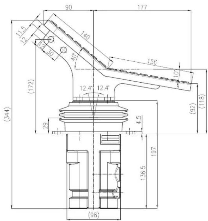
Dimensions....8
Revision history....14
natural_image
Black-and-white photo of a smiling worker operating machinery inside a vehicle cab (no visible text or symbols)Description
Hydraulic Remote Controls (HRCs) are used to activate and control directional valves or pumps from a remote and single operating station. HRCs come in hand, foot and mechanically operated versions, like the DHRCP series, provides dual pedal, single pedal, or push-only pedals providing pilot control of multiple or individual actions. It is mostly used to control travel actions, accessories, or acceleration throttle. Suitable for various applications such as excavators, drilling rigs, loaders, etc. Flexible configuration with multiple valve bodies, handles, and special functions. It has excellent handling performance, sturdy and durable design, and reliable quality.
Operation
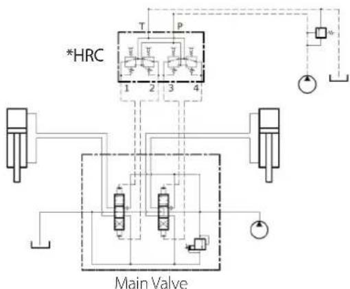
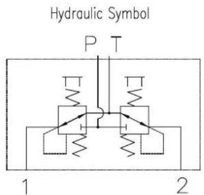
HRCs are fed a constant input pressure, from which they create reduced output pressures that vary proportionally with lever or pedal stroke. When the HRC is operated, output pilot pressure flows to the main directional control valves, precisely controlling main spool position and direction.
D-HRC Features
• Market leader with over 30 years of industry experience.
- Precision control with less leakage, close to flat hysteresis and excellent linearity.
• Reliability and Quality.
- Ergonomic efficiency and customization capabilities provide unparalleled flexibility.
flowchart
graph TD
    A["Main Valve"] --> B["1"]
    A --> C["2"]
    A --> D["3"]
    A --> E["4"]
    B --> F["T"]
    C --> G["P"]
    D --> H["+"]
    E --> I["-"]
    F --> J["Valve 1"]
    G --> K["Valve 2"]
    H --> L["Valve 3"]
    I --> M["Valve 4"]
*Schematic exemplification can be either one of the DHRC products.
natural_image
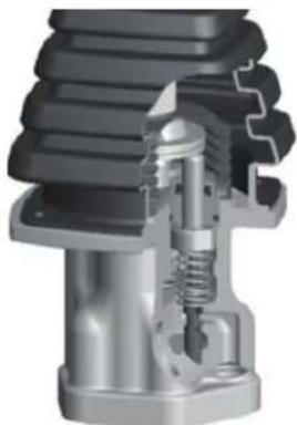
Cross-sectional view of a mechanical assembly showing internal components (no text or symbols visible)DHRCP General specification
DHRCP-Double
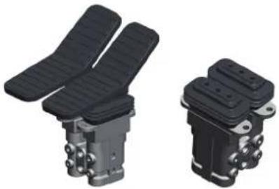
natural_image
Two black mechanical components with side-mounted sensors, shown from different angles (no text or symbols visible)DHRCP-Single
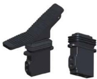
natural_image
Two black plastic mechanical components with threaded ends, shown from different angles (no text or symbols visible)DHRCP-Push only
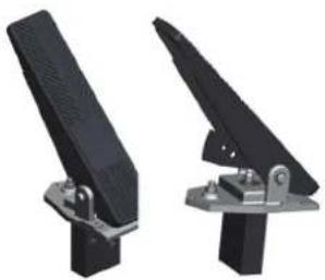
natural_image
Two black mechanical lever holders with metal brackets and mounting feet (no text or symbols visible)Hydraulic specification:
| DHRCP-Double DHRCP-Single DHRCP-Push only DHRCP-Mini | ||||
| Max. inlet pressure (bar) 70 70 50 70 | ||||
| Max. back pressure (bar) 3 | ||||
| Rated flow (LPM) 20 10 10 20 | ||||
| Output pressure (bar) 0~30 | ||||
| Fluid type Mineral oil | ||||
| Fluid temperature -20°C to 90°C | ||||
| Ambient temperature -40°C to 60°C | ||||
| Viscosity 12~400 mm^2/s | ||||
| Max level of fluid contamination 18/16/13 –ISO 4406 | ||||
Mechanical specification:
| DHRCP1/2/3-Double | DHRCP4/5/6-Single | DHRCP7-Push only | DHRCP8-Mini | ||
| Weight for refer (Kg) | Foot plate 3.6~4.4 | 2~2.5 | 1~1.4 | - | |
| Body Assy 4.8~9 | 0.7~6 | 1.1 | 6.4 | ||
| Total | 4.8~13.4 | 0.7~8.5 | 1.1~2.5 | 6.4 | |
| Operation angle range (°) | 12.4 | 12 | 20~30 | 12 | |
| Operation torque range (Nm) | 4.55 | 0.77~6.99 | 0.16~0.77 | 4.34 | |
| Lifecycle | >1,000,000 cycles | ||||
Note: Detailed operating angle and torque are provided on the drawings.
Electric specification:
| Push button | IP40 | AC 125V 5A |
| IP69K (Only for D,E grip front button) | AC 125V 3A | |
| IP67 (Only for D,E grip rear button) AC 125V 3A | ||
| Roller | IP40 | Signal 5V |
| IP69K | Signal 5V | |
| FNR | IP40 | AC 125V 3A |
| FR | IP40 | AC 125V 3A |
| Electric Detent | DC 12V/24V | |
DHRCP Configuration
| Model code example: DH | RCP 2 1 1 1 A01 | A02 | - | - | - | - | - | - |
| Model code position in catalogue: | 1.2.3.4.5 6 7 | 0 12 13.14.15 16.17.18 | ||||||
| Description: | Series | Body type | Port | damping | Foot plate | Output pressure for port1&3 | Output pressure for port2&4 | |
| 1. Damping dual pedal mono type cast iron | 000 Not applicable A## A type pressure curve B## B type pressure curve C## C type pressure curve Note: See curve table | |||||||
| 2. Damping dual pedal mono type aluminum alloy* | ||||||||
| 3. Damping dual pedal split type from top to bottom | ||||||||
| 4. Single pedal cast iron* | ||||||||
| 5. Single pedal with additional inlet cover | ||||||||
| 6. Single pedal alluminum alloy* | ||||||||
| 7. Uni-directional (push only) single pedal* | ||||||||
| 8. Damping dual mini pedal | ||||||||
| 1. BSPP G1/4 O-ring sealing | ||||||||
| 2. UNF 9/16 (ISO 11926-1) O-ring sealing | ||||||||
| 3. BSPP G1/4 O-ring sealing and BSPT R1/8 on port 5 | ||||||||
| 1. No damping | ||||||||
| 2. Standard speed with orifice 0.9[0.035]* | ||||||||
| 3. Standard speed with orifice 0.7[0.027] on inlet line | ||||||||
| 4. Special orifice 1.7[0.067] | ||||||||
Note:
Above is simple version of model code, only focus on main requirement information. If have more requirement or need more information, please find details in catalogue.
^n* means most recommend option.
Body type – Model code position 6
| Model code position 6 | Description 3D diagram 2D diagram Schematic | |||||
| 1 | Damping dual pedal mono type cast iron | 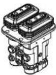 | 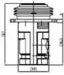 | 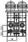 | 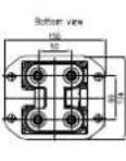 | 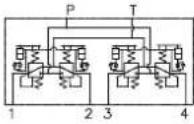 |
| 2 | Damping dual pedal mono type aluminum alloy | 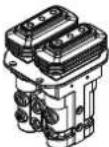 | 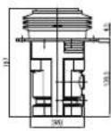 | 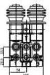 | 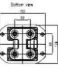 | 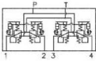 |
| 3 | Damping dual pedal split type from top to bottom cast iron | 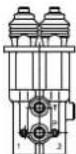 | 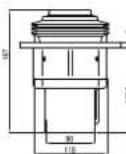 | 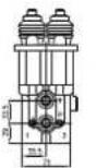 | 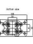 | 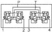 |
| 4 Single pedal cast iron | 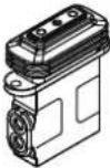 | 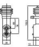 | 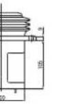 | 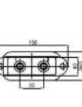 | 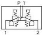 | |
| 5 | Single pedal cast iron with additional inlet cover | 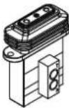 | 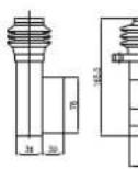 | 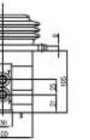 | 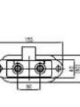 | 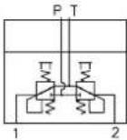 |
| 6 | Single pedal alluminum alloy | 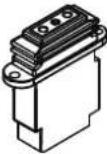 | 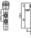 | 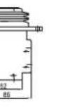 | 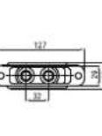 | 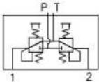 |
| 7 | Uni-directional (push only) single pedal cast iron | 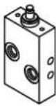 | 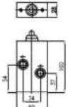 |  | 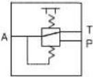 | |
| 8 | Damping dual mini pedal with shuttle cast iron | W/o shuttle for refer 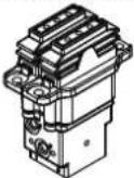 | 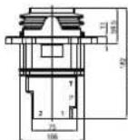 | [W0 shuttle for refer 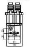 | 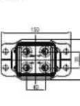 | 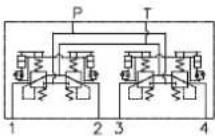 |
| Note: For body with shuttle, length increase, detail can refer dimension reference page. | ||||||
DHRCP Options
Foot plate -- Model code position 12
| Model code position 12 | Description Diagram | ||
| 0 No foot plate | |||
| 1 Standard double pedal | 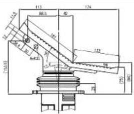 | 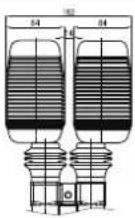 | |
| 2 Wide double pedal | 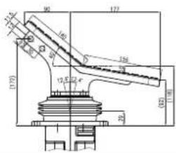 | 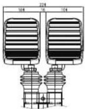 | |
| 3 Standard single pedal | 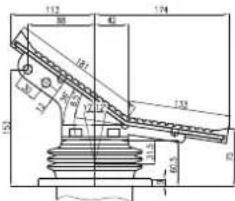 | 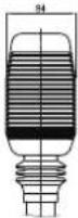 | |
| 4 Single uni-directional pedal | 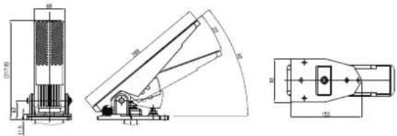 | ||
| 5 Wide single uni-directional pedal | 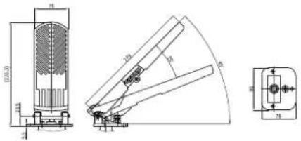 | ||
| 6 | Steelplate single pedal without rubber cover | 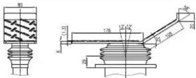 | |
| 7 Single uni-directional small pedal | 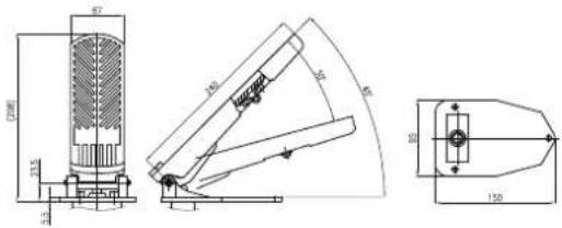 | ||
Damping dual pedal aluminum without foot plate
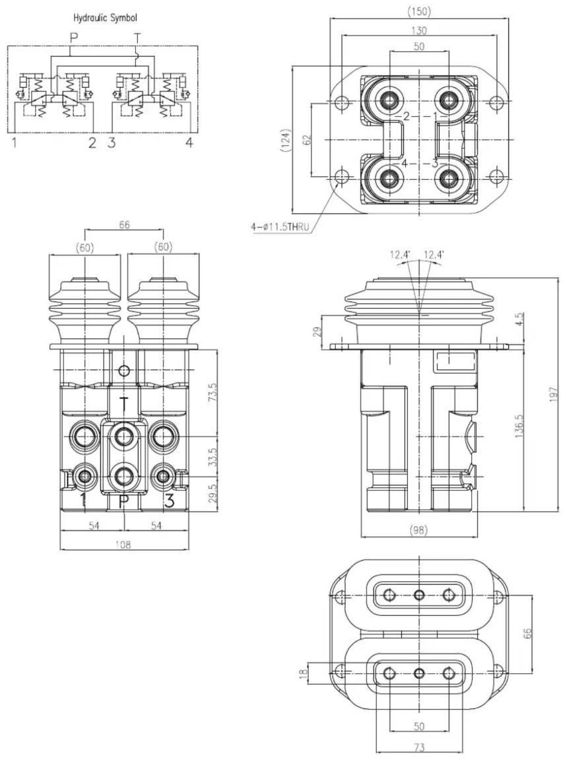
Damping dual pedal aluminum with foot plate
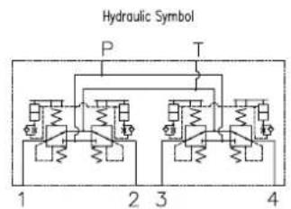
Single pedal aluminum without foot plate
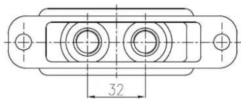
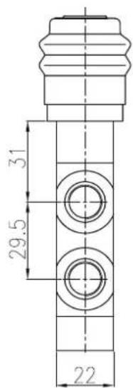
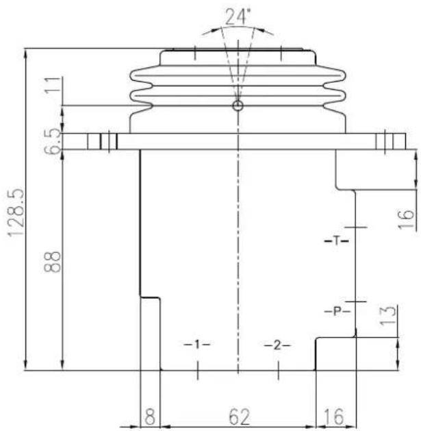
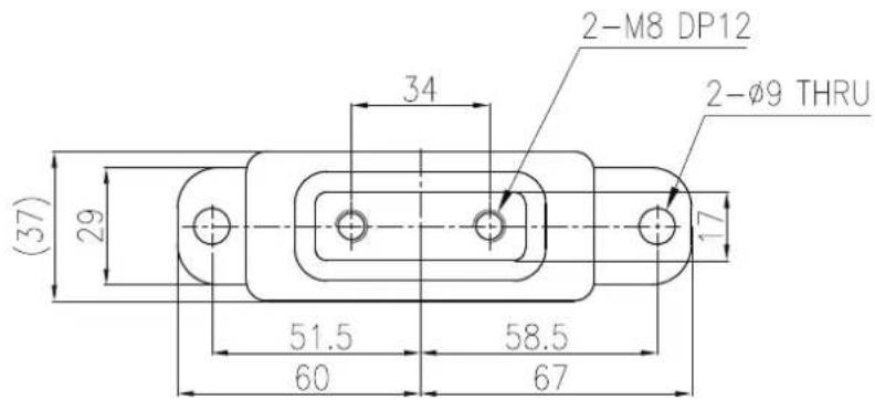
Single pedal casting iron with foot plate
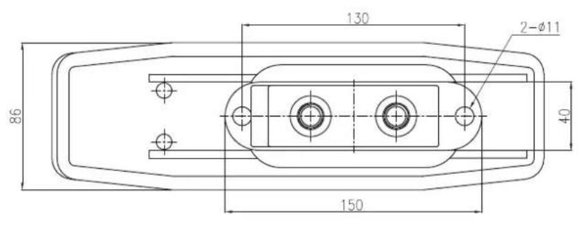
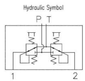
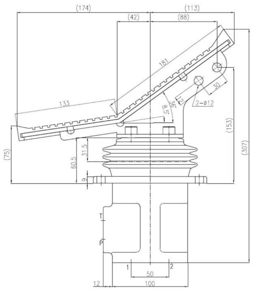
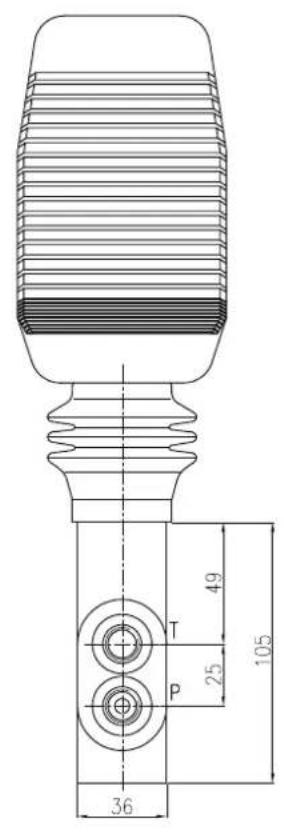
Push only pedal with foot plate
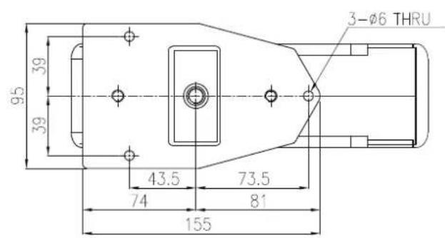
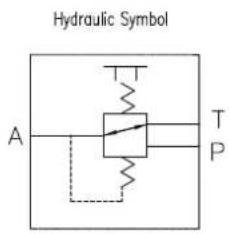
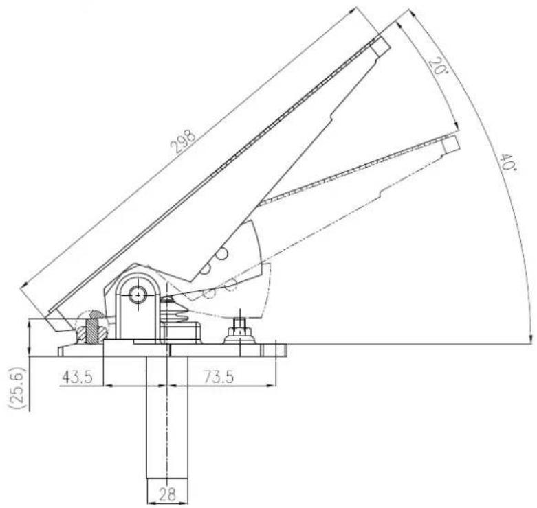
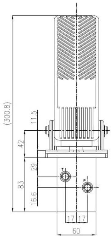
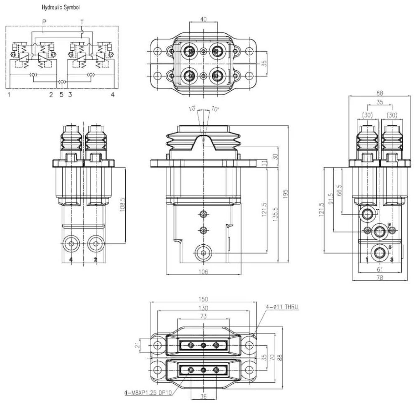
Damping dual mini pedal with shuttle without foot plate
Revision history
| Date Changed Rev | ||
| March 2024 New created A |
Products we offer:
- Cartridge valves
• DCV directional control valves
Electric converters
• Electric machines
Electric motors - Fluid Conveyance
- Gear motors
- Gear pumps
• Hydraulic integrated circuits (HICs) - Hydrostatic motors
- Hydrostatic pumps
• Industrial hydraulics - Orbital motors
- PLUS+1 ^ controllers
- PLUS+1*displays
• PLUS+1* joysticks and pedals
• PLUS+1* operator interfaces - PLUS+1* sensors
- PLUS+1*software
• PLUS+1*software services, support and training
• Position controls and sensors
• PVG proportional valves
• Steering components and systems - Telematics
Danfoss Power Solutions is a global manufacturer and supplier of high-quality hydraulic and electric components. We specialize in providing state-of-the-art technology and solutions that excel in the harsh operating conditions of the mobile off-highway and industrial markets as well as the marine sector. Building on our extensive applications expertise, we work closely with you to ensure exceptional performance for a broad range of applications. We help you and other customers around the world speed up system development, reduce costs and bring vehicles and vessels to market faster.
Danfoss Power Solutions – your strongest partner in hydraulics and mobile electrification.
Go to www.danfoss.com for further product information.
We offer you expert worldwide support for ensuring the best possible solutions for outstanding performance. And with an extensive network of Global Service Partners, we also provide you with comprehensive global service for all of our components.
Local address:
Hydro-Gear
www.hydro-gear.com
Daikin-Sauer-Danfoss
www.daikin-sauer-danfoss.com
Danfoss
Power Solutions (US) Company
2800 East 13th Street
Ames, IA 50010, USA
D-24539 Neumünster, Germany
Phone: +49 4321 871 0
Danfoss
Power Solutions ApS
Nordborgvej 81
DK-6430 Nordborg, Denmark
Phone: +45 7488 2222
Danfoss
Power Solutions Trading
(Shanghai) Co., Ltd.
Building #22, No. 1000 Jin Hai R
Jin Qiao, Pudong New District
Shanghai, China 201206
Phone: +86 21 2080 6201
- DHRCP
- Hydraulic Foot Pedals
- DHRCP is part of D-HRC series.
- Contents
- Description
- Operation
- D-HRC Features
- DHRCP General specification
- DHRCP Configuration
- DHRCP Options
- Damping dual mini pedal with shuttle without foot plate
- Revision history
- Products we offer:
- Go to www.danfoss.com for further product information.
- Hydro-Gear
- Daikin-Sauer-Danfoss
- Danfoss
Brand : DANFOSS
Model : DHRCP
Category : Uncategorized