EPJ 500-E - Saw Power Craft - Free user manual and instructions
Find the device manual for free EPJ 500-E Power Craft in PDF.


| Brand | Power Craft |
| Model | EPJ 500-E |
| Product Type | Electronic Pendulum Jig Saw |
| Power Consumption | 500 W |
| Voltage | 230 V ~ 50 Hz |
| Cutting Rate (No-Load) | 480 - 2500 strokes/min |
| Stroke Height | 16 mm |
| Cutting Depth in Wood | 60 mm |
| Cutting Depth in Plastic | 20 mm |
| Cutting Depth in Iron | 5 mm |
| Bevel Cuts | Up to 45° (left and right) |
| Pendulum Action Stages | 3 stages (0, 1, 2) |
| Speed Control | Electronic, variable |
| Dust Extraction | Socket for vacuum cleaner |
| Sound Pressure Level (LPA) | 89 dB(A) |
| Sound Power Level (LWA) | 99.6 dB(A) |
| Vibration (handle) | 3.2 m/s² |
| Weight | 1.7 kg |
| Insulation | Double insulation |
| Included Accessories | Transparent guard, anti-splinter device, Allen key |
| Warranty | 1 year |
Frequently Asked Questions - EPJ 500-E Power Craft
User questions about EPJ 500-E Power Craft
0 question about this device. Answer the ones you know or ask your own.
Ask a new question about this device
Download the instructions for your Saw in PDF format for free! Find your manual EPJ 500-E - Power Craft and take your electronic device back in hand. On this page are published all the documents necessary for the use of your device. EPJ 500-E by Power Craft.
USER MANUAL EPJ 500-E Power Craft
GB Operating Instructions electronic pendulum jig saw
POWER CRAFT®
CE
Art.-No.: 43.206.02
natural_image
Line drawing of a mechanical device with no visible text or symbolsEPJ 500-E

Please read the operating instructions carefully before assembling and using
GB Please pull out pages 2-3
GB
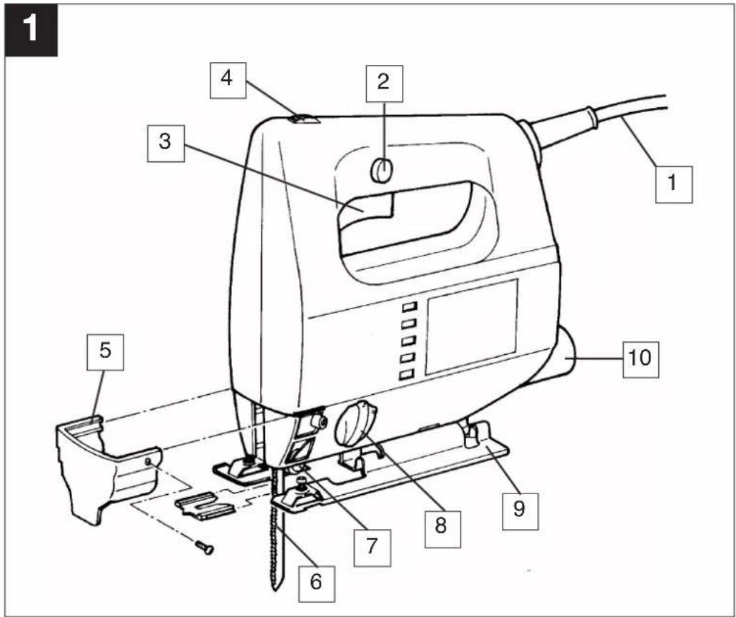
Description
1 Power cable
2 Locking button
3 On/Off switch
4 Knurled screw for regulating the speed
5 Inspection guard
6 Saw blade
7 Guide roller
8 Adjustment lever for pendulum action
9 Adjustable base plate
10 Dust extractor socket
General safety and accident prevention regulations
To work safely with this machine and to prevent accidents it is imperative to read the following safety regulations and operating instructions in full and to put all the information into practice.
●Always check the machine, the power cable and the plug before use. Only ever use the machine if it is in perfect, undamaged condition. Damaged parts are to be repaired or replaced immediately by a qualified electrician.
●Always pull the plug out of the power socket before carrying out any work on the machine, before changing the tool and in periods of non-use.
●Always run the power cable away from the back of the machine to guard it from damage.
- For outdoors work use only suitably approved extension cables. The extension lead must have a minimum cross section of 1.5mm^2 . The plug connectors must have earthing contacts and be rainwater-proof.
- Keep the machine in a safe place and out of the reach of children.
●Always wear goggles, safety gloves and ear muffs when cutting. Wear a breathing mask on dusty jobs.
●Never leave any tool keys or adjustment spanners in position on the machine. Before switching on, check that all keys and adjustment spanners have been removed.
- Secure the workpiece (with a clamp) so that it cannot slip.
●It is prohibited to use the machine on asbestos materials. Please note the accident prevention regulations in force in your country.
- Use only original spare parts.
●Repairs are to be carried out by qualified electricians only.
●The level of noise at the workplace may exceed 85 dB(A). In this case you will need to introduce noise protection measures for the user. The noise produced by this electric tool is measured in accordance with ISO 3744, NFS 31-031 (84/537/EEC).
●Make sure of your footing. Avoid abnormal working positions. - Keep your electric tool out of the rain. Never use electric tools in wet or damp conditions, and never use them near inflammable liquids.
●Never carry the machine by its power cable. Keep the power cable safe from damage. Oil, solvent and sharp edges can damage cables. - Keep your workplace tidy.
●Make sure the power switch is off before inserting the plug in the socket.
●Wear suitable clothing. Never wear loose-fitting clothes or jewelry. Use a hair-net on long hair. - For your own safety, use only the manufacturer's accessories and attachments.
- Use only sharp saw blades that are in perfect condition. Replace bent and cracked saw blades immediately.
●After switching off the jigsaw, do not press against the side of the blade to bring it to a halt.
●Always cut at a steady rate of progress. This will prevent accidents and prolong the life of your jigsaw and the blade.
GB
Operating instructions for the EPJ 500 E electronic jig saw
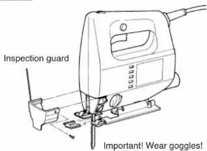
Fitting the transparent guard
Slide the transparent guard onto the machine as shown in Fig. 1 and secure it with the supplied screws. Push the anti-splinter device onto the soleplate as shown.
STARTING UP
Instant response operation (Figure 3)
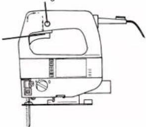
Switching on: Press the On/Off switch Switching off: Release the On/Off switch
Continuous operation
Switching on: Press the On/Off switch, keep pres sed and lock with the locking button Switching off: Press the On/Off switch and release
Electronic speed control setting (Figure 4)
You can use the speed controller to set the speed required. Turn the speed controller in PLUS direction to increase the speed, turn it in MINUS direction to reduce the speed. The ideal blade speed varies with the material and working conditions.
The general rules for cutting speeds during machining operations apply in this case too.
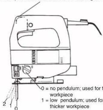
Pendulum (Figure 4)
The adjustable three-stage pendulum action makes it possible to adjust the blade penetration on the upward stroke for the various working material. Optimal cutting performance is thereby achieved. The saw blade is lifted from the workpiece in the downward stroke. This results in improved chip ejection while substantially reducing frictional heat and increase the life expectancy of the saw blade.
The pendulum action can be adjusted to one of three stages.
Stage 0 = Pendulum action off (best for metal) Stage 1 = low pendulum action (best for thick wood) Stage 2 = high pendulum action (best for thin wood)
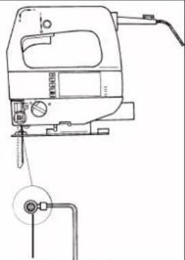
Changing the saw blade (Figure 2)
Switch off the jigsaw and remove the plug from the power socket before changing the blade or carrying out any other work on the jigsaw.
Use the supplied allen key to undo the two screws on the ram (Figure 2). Slide the saw blade into the guide slot and up to the stop between the piston rod and the retention clip. Use the supplied allen key to tigh-
ten the two screws. The teeth of the saw blade must face in cutting direction. Make sure that the saw blade sits properly in the guide slot of the ram and roller.
Adjusting the base
(for mitering and sawing near edges, Figure 5) For mitre and bevel cuts you can swivel the base by up to 45° in either direction after undoing the two screws on the bottom. The angles 15°, 30° and 45° are marked but you can adjust the saw to any angle between these markings as required.
To adjust the cutting angle, undo the two screws (Figure 5) until you can just about move the base. Adjust to the required angle and re-tighten the two screws.
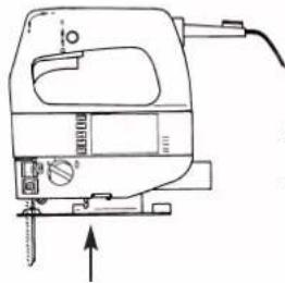
To enable you to saw right up to the edge, the base can be pushed backward. To do so, undo the two screws underneath (Figure 5) and push the base to the back. Re-tighten the two screws.
Dust extraction
The jigsaw is equipped with a dust extractor socket. Any vacuum cleaner can be connected to the socket at the rear of the jigsaw. If you require a special adapter, please contact the manufacturer of your vacuum cleaner.
TECHNICAL DATA
| Nominal voltage: 230 V ~ 50 Hz | |
| Power consumption: 500 W | |
| Cutting rate: 480 - 2500 strokes/min. | |
| Stroke height: 16 mm | |
| Cutting depth in wood: 60 mm | |
| Cutting depth in plastic: 20 mm | |
| Cutting depth in iron: 5 mm | |
| Mitre cuts: up to 45° (left and right) | |
| Sound pressure level LPA: 89 dB(A) | |
| Sound power level LWA: 99.6 dB(A) | |
| Vibration aw | 3,2 m/s2 |
| Double isolation | |
| Weight 1,7 Kg | |
Vibration measured on the handle acc. to ISO 8662-8.
GB
1
Fitting the inspection guard
4
Turn the speed controller to increase the cutting rate
2
Changing the saw blade
Insert the saw blade in the ram up to the stop and tighten the two screws of the retention clip.
Important: Make sure that the saw blade sits properly in the slot of the roller and ram.
natural_image
Line drawing of a sewing machine with attached pulley and rope (no text or symbols)Releasing the saw blade: Turn screws anticlockwise.
5
natural_image
Line drawing of a mechanical device with no visible text or symbols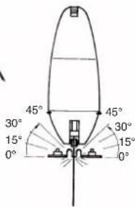
Undo the two screws to set the base to an angle of up to 45^ on the right or left side.
3
On/Off switch
Locking button
natural_image
Line drawing of a mechanical device with no visible text or symbolsSwitching on: Press the On/Off switch
Continuous operation: Lock the On/Off switch with the
locking button
Switching off: Press the On/Off switch
and release
6
Cutting veneered chipboard:
- Use a fine saw blade
- Position the base on the uncovered area
- Advance the saw with little force
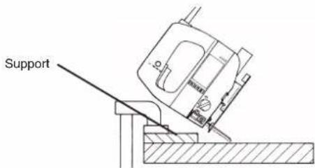
Cutting holes: Not possible in chipboard and wood unless you drill a hole first. Press the jigsaw firmly against the support and move slowly in cutting direction.
| D | GB | I | F | NL | E |
| EG KonformitätserklärungDer Unterzeichnende erklärt im Namen der Firma | EC Declaration of ConformityThe Undersigned declares, on behalf of | Dichiarazione di conformità CEIl sottoscritto dichiara in nome della ditta | Déclaration de Conformité CELe soussigné déclare, au nom de | EC ConformiteitsverklaringDe ondertekenaar verklaart in naam van de firma | Declaracion CE de ConformidadPor la presente, el abajo firmante declara en nombre de la empresa |
| ISC GmbH, International Service Center · Eschenstraße 6 · D-94405 Landau/Isar | |||||
| daß die | that the | che la | que | dat de | que el/la |
| Maschine/Produkt | Machine / Product | macchina/prodotto | la machine / le produit | machine/produkt | màquina/producto |
| Elektronik-Stichsäge | Electronic jig saw | Foretto elettronico | Scle sauteuse électronique | Elektronische decoupeerzaag | Serrucho de punta electrónico |
| Marke | produced by: | marca | du fabricant | merk | marca |
| CRAFT | |||||
| Typ | Type | tipo | Type | type | tipo |
| EPJ 500-E | |||||
| – Seriennummer auf dem Produkt –der☑EG Maschinenrichtlinio89/392/EWG mit Änderungen☑EG Niederspannungs-richtlinie 73/23 EWG☑EG Richtlinie Elektromagnetische Verträglichkeit89/336 EWG mitÄnderungen entspricht. | – Serial number specified on the product - is in accordance with the☑EC Directive regarding machinery 89/392 EEC, as amended;☑EC Directive regarding low-voltage equipment 73/23 EEC;☑EC Directive regarding electromagnetic compatibility 89/336 EEC, as amended. | – numero di serie sul prodotto - corrisponde☑alla Direttiva CE sulle macchine 89/392/CEE con modifiche☑alla Direttiva CE sulla bassa tensione 73/23 CEE☑alla Direttiva CE sulla compatibilità elettromagnetica 89/336 CEE con modifiche | – no. série indiqué sur le produit - correspond(ent) à la☑Directive CE relative aux machines 89/392 CEE avec les modifications y apportées;☑Directive CE relative aux basses tensions 73/23 CEE;☑Directive CE relative à la compatibilité électromagnétique 89/336 CEE avec les modifications y apportées. | – serienummer op het produkt-conform de volgende richtlijnen is:☑EG machinerichtlijn 89/392/EWG met wijzigingen☑EG laagspanningsrichtlijn 73/23 EWG☑EG richtlijn Elektromagnetische compatibilitéit 89/336 EWG met wijzigingen avec les modifications y apportées. | – No. de serie en el producto: satisface las disposiciones pertinentes siguientes:☑Disposición de maquinaria de la CE 89/392/CEE con modificaciones☑Disposición de baja tensión de la CE 73/23 CEE☑Disposición de la compatibilidad electro-magnética de la CE 89/336 CEE con modificaciones. |
| EN 550144-1; EN 50144-2-10; EN 292-1; EN 292-2/A1; EN 55014; EN 50082-1; EN 60555-2; EN 60555-3 | |||||
| Landau/Isar, den24.06.1998PflaumProdukt-Management-L | Landau/Isar, (date)24.06.1998PflaumHead of Product Management | Landau/Isar,1”24.06.1998PflaumIl Responsabile della produzione | Landau/Isar, (date)24.06.1998PflaumDirection Gestion Produits | Landau/Isar, datum24.06.1998PflaumHoofd produkt management | Landau/Isar24.06.1998PflaumDirector de gestión productos |
Archivierung / For archives: STP-0526-21-909-E
Replacement parts drawing EPJ 500-E Art.-No.: 43.206.02, I.-No.: 91019
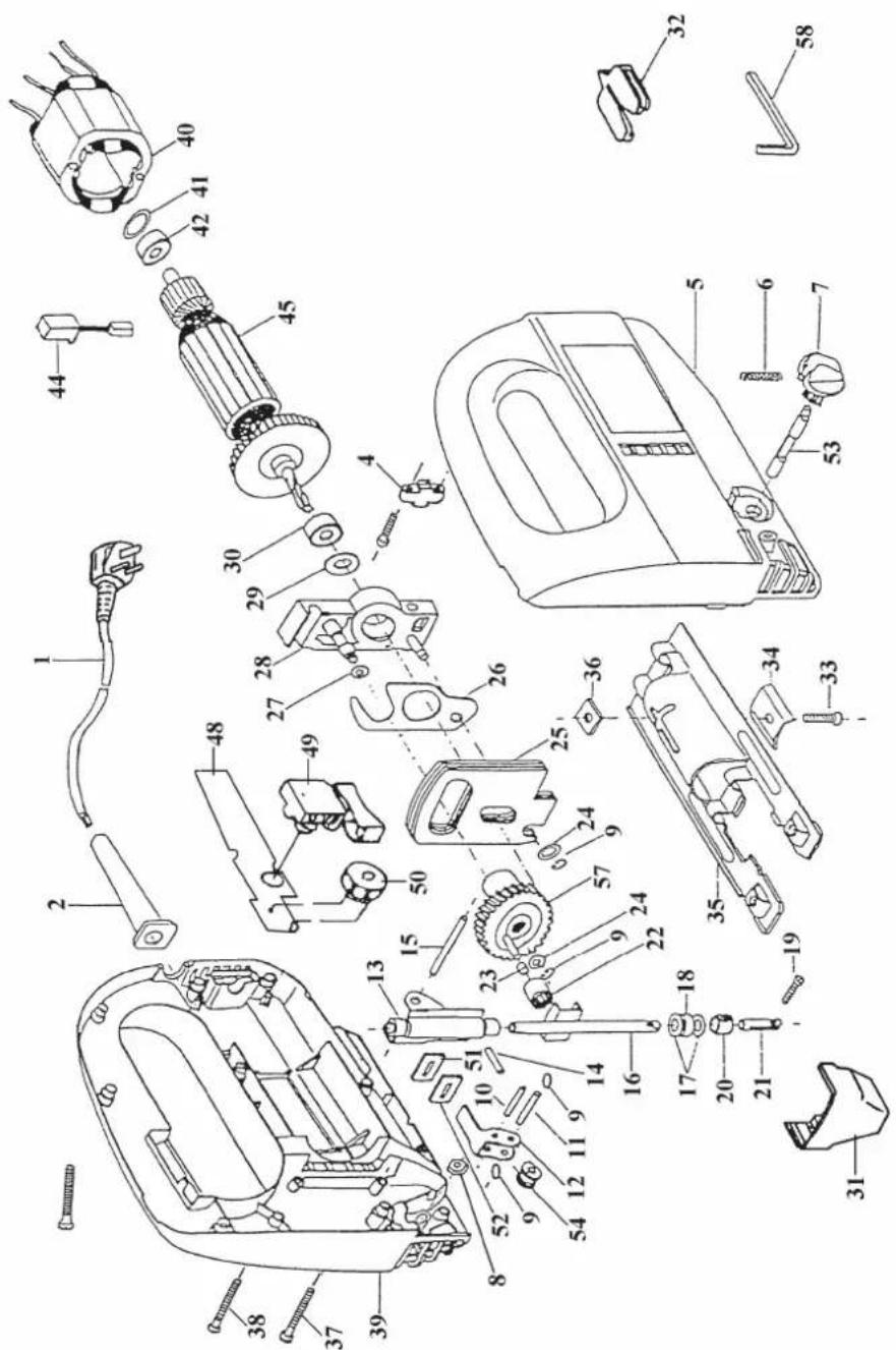
Replacement parts list EPJ 500-E Art.-No.: 43.206.02, I.-No.: 91019
| Item Designation Replacement Part No. | |
| 01 Mains cable 43.206.10.03 | |
| 02 Anti-kink sleeve 43.206.00.01 | |
| 04 Cable grip 43.206.00.02 | |
| 05 Left half of case 43.206.00.03 | |
| 06 Compression spring 43.206.00.04 | |
| 07 Rotary knob 43.206.00.05 | |
| 08 Nut 43.206.00.06 | |
| 09 Circlip ring 43.206.00.07 | |
| 10 Bolt 43.206.00.08 | |
| 11 Bolt 43.206.00.09 | |
| 12 Guide roller holder 43.206.00.10 | |
| 13 Bracket 43.206.00.11 | |
| 14 Pin 43.206.00.12 | |
| 15 Bolt 43.206.00.13 | |
| 16 Piston rod | 43.206.00.14 |
| 17 Washer | 43.206.00.15 |
| 18 Felt seal | 43.206.00.16 |
| 19 Screw | 43.206.00.17 |
| 20 Roller | 43.206.00.18 |
| 21 Connectorl | 43.206.00.19 |
| 22 Bearing | 43.206.00.20 |
| 23 Sleeve | 43.206.00.21 |
| 24 Washer | 43.206.00.22 |
| 25 Counterweight | 43.206.00.23 |
| 26 Eccentric plate | 43.206.00.24 |
| 27 Lock ring | 43.206.00.25 |
| 28 Bearing flange | 43.206.00.26 |
| 29 Spacer ring | 43.206.00.27 |
| 30 Ball bearing 60027 | 43.206.00.28 |
| 31 Transparent guard 43.206.00.29 | |
| 32 Anti-splinter device | 43.206.00.30 |
| 33 Screw | 43.206.00.31 |
| 34 Clamping element | 43.206.00.32 |
| 35 Soleplate | 43.206.00.33 |
| 36 Special nut | 43.206.00.34 |
| 37 Self-tapping screw 43.206.00.35 | |
| 38 Self-tapping screw 43.206.00.36 | |
| 39 Right half of case | 43.206.00.37 |
| 40 Stator | 43.206.00.38 |
| 41 Rubber ring | 43.206.00.39 |
| 42 Ball bearing 80026 | 44.302.00.F9 |
| 44 Carbon brush with holder | 43.206.00.41 |
| 45 Rotor | 43.206.00.42 |
| 48 Printed circuit-board | 43.206.00.43 |
| 49 ON/OFF switch | 43.206.00.44 |
| 50 Speed controller | 43.206.00.45 |
| 51 Clip 43.206.00.46 | |
| 52 Felt seal | 43.206.00.47 |
| 53 Axle | 43.206.00.48 |
| 54 Guide roller | 43.206.00.49 |
| 57 Gearwheel | 43.206.00.52 |
| 58 Allen key | 43.206.00.53 |
GB WARRANTY CERTIFICATE
The guarantee period begins on the sales date and is valid for 1 year.
Responsibility is assumed for faulty construction or material or functional defects.
Any necessary replacement parts and necessary repair work are free of charge.
We do not assume responsibility for consequential damage. Your statutory rights are not affected.
Your customer service partner
Service UK:
GB Einhell UK Ltd
Brook House, Brookway
North Chesire Trading Estate
Prenton, Wirral, Chesire
CH 43 3DS
Tel. 0151 6084802, Fax 0151 6086339
Technical specification subject to change
EH 07/00
- GB
- Description
- General safety and accident prevention regulations
- Operating instructions for the EPJ 500 E electronic jig saw
- Fitting the transparent guard
- STARTING UP
- Instant response operation (Figure 3)
- Continuous operation
- Electronic speed control setting (Figure 4)
- Pendulum (Figure 4)
- Changing the saw blade (Figure 2)
- Adjusting the base
- Dust extraction
- 1
- 4
- 2
- 5
- 3
- 6
- GB WARRANTY CERTIFICATE
Brand : Power Craft
Model : EPJ 500-E
Category : Saw