
IFD550 - Gps Avidyne - Free user manual and instructions
Find the device manual for free IFD550 Avidyne in PDF.


| Product Type | Integrated Flight Display GPS/NAV/COM |
| Model | IFD550 (Black or Grey Bezel) |
| Part Number | 700-00182-020 (Black), 700-00182-120 (Grey) |
| Bezel Dimensions (H x W) | 4.58 in x 6.25 in (116 mm x 159 mm) |
| Depth (with connectors) | 11.00 in (279 mm) |
| Weight (installed, less wiring) | 8.78 ± 0.25 lbs |
| Power Input Voltage | 9-33 VDC |
| Max Current (28V, Main) | 2.07 A |
| Display Size | 5.7 in diagonal |
| Display Resolution | 640 x 480 pixels |
| GPS Channels | 16 (13 GPS, 3 GPS/WAAS/SBAS) |
| GPS Position Accuracy | 3.4 m (horizontal) |
| GPS Update Rate | 5 Hz |
| VHF Comm Power | 16 W or 10 W (selectable) |
| VHF Comm Frequency Stability | < 2.5 ppm |
| VHF Nav Capabilities | VOR, LOC, ILS, Glideslope |
| Attitude Reference System (ARS) | Static accuracy ±1.0°, dynamic ±2.5° |
| Interfaces | ARINC 429, RS-232, RS-170 Video, USB |
| Cooling Requirement | Not required |
| Compliance | TSO-C146d, TSO-C169a, TSO-C151d (TAWS-B) and others |
| Maintenance | Periodic VOR checks, cleaning with soft cotton cloth |
| Safety Functions | TAWS-B, Forward Looking Terrain Alerting, Terrain/Obstacle alerts |
| Spare Parts / Upgrades | Ship kits (850-00182-xxx); optional activation for 16W, radar, TAWS |
Frequently Asked Questions - IFD550 Avidyne
User questions about IFD550 Avidyne
0 question about this device. Answer the ones you know or ask your own.
Ask a new question about this device
Download the instructions for your Gps in PDF format for free! Find your manual IFD550 - Avidyne and take your electronic device back in hand. On this page are published all the documents necessary for the use of your device. IFD550 by Avidyne.
USER MANUAL IFD550 Avidyne
Click the icon for a tutorial on how to use the interactive portion of this manual.
AVIDYNE™
IFD5XX / IFD4XX / Atlas Integrated Flight Display
Installation Manual
for Fixed Wing Applications


Revision History
| Document Number | 600-00299-000 | Control Category | CC2 | ||
| Revision | Description | ECO | Date | ||
| 00 | Initial Release | ECO-14-207 | 07/09/14 | ||
| 01 | Release 10.0.1.0 | ECO-14-283 | 08/21/14 | ||
| 02 | Release 10.0.2.0 | ECO-14-356 | 11/12/14 | ||
| 03 | Release 10.0.3.0 | ECO-14-424 | 02/02/15 | ||
| 04 | Release for TSO | ECO-15-154 | 04/09/15 | ||
| 05 | Define MLB100 TSO part number | ECO-15-385 | 09/29/15 | ||
| 06 | Support WiFi Bluetooth activation utility | ECO-15-425 | 11/06/15 | ||
| 07 | Release 10.1.1.0 | ECO-15-469 | 12/04/15 | ||
| 08 | Release 10.1.2.0 | ECO-16-054 | 03/01/16 | ||
| 09 | Add EASA Verbiage and 10.1.3 | ECO-16-054 | 06/23/16 | ||
| 10 | Release 10.2 | ECO-17-001 | 02/03/17 | ||
| 11 | Minor error correction to D-44, D-45, Table 73 | ECO-17-060 | 03/08/17 | ||
| 12 | Minor error correction to D-44, D-45, Table 73 | ECO-17-066 | 03/15/17 | ||
| 13 | Release 10.2.1.0 | ECO-18-013 | 02/09/18 | ||
| 14 | Release 10.2.1.0 minor corrections | ECO-18-066 | 03/07/18 | ||
| 15 | Add Proline 21 EFIS /APS 3000 AP | ECO-18-138 | 05/16/18 | ||
| 16 | Update for GPS roll-over of the 10 bit number of weeks, Update Table 1 and 2 | ECO-19-025 | 02/08/19 | ||
| 17 | Release 10.2.3.1 | ECO-19-050 | 04/29/19 | ||
| 18 | Added ARINC429 output tables, Proline 21 schematics and configuration settings. | ECO-19-190 | 08/16/19 | ||
| 19 | Release 10.2.4.1 | ECO-19-289 | 01/16/20 | ||
| 20 | Updated with part 25 aircraft, updated options P/N's, added to the Mods table, Added Honeywell EGPWS, added RDR2100, RDS Radars, fixed DME42 strapping, added Honeywell EPGWS interconnects, added password configuration instructions added GTX3000, NGT700, MST70B BXT65XX interconnects | ECO-20-093 | 08/24/20 | ||
| 21 | Release 10.2.5.1, Becker remote | ECO-20-162 | 02/05/21 | ||
| 22 | Release 10.2.6.1 | ECO-21-049 | 03/09/21 | ||
| 23 | Adding Atlas, update IRU Cal | ECO-21-062 | 04/02/21 | ||
| 24 | Release 10.3 | ECO-21-236 | 05/17/22 | ||
| 25 | Release 10.3.1.2, add Atlas FMS Only | ECO-22-268 | 02/10/23 | ||
All materials copyrighted, including images that represent the software.
Copyright 2014-2021 Avidyne Corporation. All rights reserved.
The latest installation manuals are available to authorized dealers on the web at https://www.dealers.avidyne.com
Avidyne ^® is a registered trademark of Avidyne Corporation.
Table of Contents
1. General Information 14
1.1 Introduction.... 14
1.2 IFD Configurations.... 14
1.3 Bendix King Part Numbers 18
1.4 Unit Modifications 20
1.5 Technical Specifications 26
1.5.1 IFD5XX Specifications 26
1.5.2 Atlas Specifications.... 33
1.6 Regulatory Compliance 37
1.6.1 Applicable TSOs 37
1.6.2 TSO Deviations.... 38
1.6.3 Non-TSO Functions 40
1.6.4 Partial TSO Functions.... 40
1.6.5 Open Problem Report.... 41
1.7 Software and Hardware Design Assurance Levels 41
1.8 Environmental Qualification Forms.... 42
1.9 Databases.... 42
1.10 Electronic Map Display Information 42
1.11 GPS Fault Detection and Exclusion (FDE) 43
1.12 Terrain Alerting and Warning System.... 43
1.13 FIS-B ADS-B Weather Information 44
1.14 Part 23 STC Approved Model List.... 44
1.15 Part 25 STC Approved Model List.... 44
1.16 Avidyne Supplied Material 45
1.16.1 Product Ship Kits 45
1.16.2 Optional Ship Kits 46
1.17 Materials Required but not Supplied 47
2. Installation Considerations...... 48
2.1.1 VFR Installation 48
2.1.2 IFR Installation 48
2.2 Garmin GNS Replacement Considerations.... 51
2.2.1 Circuit Breakers 51
2.2.2 WAAS Enabled: 51
2.2.3 TAWS: 52
2.2.4 TAWS Audio: 52
2.2.5 Installation with Avidyne AXP340/322 Transponder: 52
2.2.6 Additional Installation Data Sources.... 52
2.2.7 Electrical Load Analysis (ELA) 53
2.3 Optional Installation Features 54
2.4 IFD Interfaces 55
2.5 Pre-Installation Checklist 62
3. Antenna Installation 63
3.1 Antenna Bonding 63
3.2 Antenna Environmental Qualifications....63
3.3 GPS Antenna....63
3.3.1 GPS Antenna Location 64
3.3.2 GPS Antenna Bonding....68
3.3.3 GPS Antenna Cable 68
3.3.4 GPS Coaxial Cable Connector 68
3.3.5 Approved GPS Antennas.... 69
3.3.6 GPS Interference 69
3.3.7 Ground Plane.... 70
3.3.8 Dual IFD Installations.... 70
3.3.9 Anti-Ice Protection 70
3.4 VHF Communication Antenna 71
3.4.1 Antenna Environmental Qualifications.... 71
3.4.2 VHF Communication Cable 71
3.4.3 VHF Coaxial Cable Connector 71
3.4.4 Voltage Standing Wave Ratio....71
3.4.5 VHF Antenna 71
3.4.6 Antenna Ground Plane 71
3.5 Navigation Antennas.... 71
3.5.1 VOR/LOC Antenna 71
3.5.2 Navigation Coaxial Cable 71
3.5.3 Navigation Coaxial Cable Connector....72
3.5.4 Diplexer....72
3.6 Glideslope Antenna 72
3.6.1 Glideslope....72
4. Electrical Installation....73
4.1 Wire Type 73
4.2 Wire and Connector Identification 73
4.3 Wire Routing....73
4.4 Shield Grounds 73
4.5 Wire Harness Overbraid 73
4.5.1 Existing Equipment 73
4.5.2 Severe Lightning Transient Environment 73
4.5.3 Copper Overbraid Installation 74
4.6 IFD Connectors.... 74
4.7 Byteflight Digital Data Bus Consideration – Dual IFD Installations 75
4.7.1 Databus Wiring - Replacement Installations.... 75
4.7.2 Databus Wiring – New Installations.... 75
4.8 Circuit Protection 75
4.9 Power Distribution.... 75
4.10 Electrical Load Analysis....77
4.11 Low Power Behaviors....77
5. Mechanical Installation 78
5.1 Equipment Location – New Installations.... 78
5.1.1 Determining the IFD Field of View 78
5.1.2 Navigation and TAWS (if enabled) Annunciation 79
5.1.3 Course Deviation Indicator 81
5.1.4 Instrument Panel Cutout.... 81
5.1.5 Requirements for Tray Installation.... 81
5.2 Equipment Location - Replacement Unit 82
5.3 Equipment Location - Atlas Unit 82
5.4 Angle of Regard 82
5.5 Unit Installation/Removal 83
5.5.1 IFD IFD5XX/4XX Installation/Removal 83
5.5.2 Atlas Installation/Removal 83
5.6 Internal Cooling....83
5.7 External Cooling 84
5.8 Electrical Bonding 84
5.9 Aircraft Considerations 84
5.10 Weight and Balance 84
5.11 Compass Safe Distance 84
6. System Installation.... 86
6.1 Pin Function List 86
6.1.1 P1001 Main Connector 86
6.1.2 P1002 Communication Connector....89
6.1.3 P1006 Navigation Connector....90
6.1.4 P1050 Additional I/O Connector 91
6.1.5 Altitude Gray Code 92
6.1.6 Heading Input 92
6.1.7 Main Course Deviation Indicator Output.... 93
6.1.8 Serial Data 97
6.1.9 ARINC 429....97
6.1.10 ARINC 453.... 101
6.1.11 RS170 Video.... 101
6.1.12 Com/VOR/ILS Audio Electrical Characteristics 101
6.1.13 VOR/ILS Indicator Electrical Characteristics 103
6.1.14 DME Tuning.... 103
6.2 Bezel Lighting 104
6.3 Traffic System.... 105
6.4 Lightning Detection System.... 105
6.5 Datalink Weather 105
6.6 Audio Panels.... 106
6.7 GAD 42....107
6.8 Air Data System Sources.... 108
6.9 Heading System Sources 110
6.10 Multifunction Displays.... 111
6.11 Forward Looking Terrain Alerting 111
6.11.1 Audio.... 111
6.11.2 Annunciators.... 111
6.12 Fixed Wing TAWS Unlock 112
6.12.1 Fixed Wing TAWS Audio 112
6.12.2 Fixed Wing TAWS Annunciators 112
6.13 External TAWS/EGPWS Output 113
6.14 ADS-B Transponder/UAT Output 113
6.15 Autopilot.... 120
6.16 Video Input.... 120
6.17 Radar Display and Control.... 121
7. Configuration and Checkout 122
7.1 Wiring Check 122
7.2 Mounting Check.... 122
7.3 Chassis ID Setting 122
7.4 Unit Installation 123
7.5 Configuration 123
7.5.1 Maintenance Mode 123
7.5.2 Password PIN Page.... 124
7.5.3 ARINC 429 Port Configuration 126
7.5.4 RS-232 Port Configuration.... 132
7.5.5 Main System Configuration 137
7.5.6 Main Input Configuration.... 142
7.5.7 Main Lighting Configuration.... 143
7.5.8 Main Discrete I/O 147
7.5.9 Main CDI/OBS Config Page 149
7.5.10 VOR/LOC/GS CDI 152
7.5.11 VOR/LOC/GS ARINC 429 Configuration.... 154
7.5.12 Com Setup.... 155
7.5.13 GPS Setup 156
7.5.14 Main ARINC 429 Port 3 Configuration.... 158
7.5.15 GPS Legacy Avionics System (GLAS) 158
7.5.16 GDL Configuration Pages.... 160
7.5.17 Remote XPDR Configuration.... 161
7.5.18 Voice Call Outs Configuration 163
7.5.19 Wireless Portables.... 164
7.5.20 WiFi Setup 164
7.5.21 Bluetooth Setup 165
7.5.22 IRU Calibration, IFD545, IFD550, Atlas.... 169
7.5.23 RDR2000 Radar Configuration.... 172
7.5.24 Fixed Wing TAWS enablement and configuration.... 173
7.5.25 Stormscope Test Page 175
7.5.26 GAD 42 Configuration.... 176
7.5.27 Other System Diagnostics Pages.... 177
7.6 Checkout.... 179
7.6.1 Database Check 179
7.6.2 Airplane Flight Supplement Check 179
7.6.3 Instructions for Continued Airworthiness 179
7.6.4 Aircraft Weight and Balance 179
7.6.5 Electrical Load Analysis.... 179
7.6.6 GPS Signal Acquisition.... 179
7.6.7 VHF COM Checkout 180
7.6.8 VOR/LOC/GS Checkout 180
7.6.9 Autopilot.... 180
7.6.10 Magnetic Compass Swing 181
7.6.11 IFD Bezel and Display Lighting.... 181
7.6.12 External Annunciators and Switches 181
7.6.13 Placards 181
7.6.14 Self-test Page 181
7.6.15 Dual IFD Configuration 182
7.6.16 Heading Interface Check 182
7.6.17 ADS-B Output 182
7.6.18 Fixed Wing TAWS Checkout (if enabled) 182
8. Flight Checks.... 184
8.1 GPS Verification 184
8.2 VHF COM Flight Check 184
8.3 VOR Flight Checks 184
8.4 ILS Flight Checks.... 184
8.5 Autopilot Checks.... 184
8.6 Sensors Verification.... 184
8.7 Fixed Wing TAWS Checks (if enabled) 185
9. Glove Validation Procedures.... 186
10. Software and Database Update Procedures...... 187
10.1 Data Updates.... 187
10.2 Datalogs Download.... 190
10.3 Software Update 192
11. Periodic Maintenance.... 193
11.1 Equipment Calibration 193
11.2 VOR Checks 193
11.3 Cleaning.... 193
12. Factory Service Policies and Procedures...... 194
12.1 Technical Support.... 194
12.2 General Service Procedures 194
13. Bezel and Display Cleaning 196
Appendix A: Environmental Qualification Form...... 197
Appendix B: STC Permission 200
Appendix C: Mechanical Drawings 201
Appendix D: Electrical Interface Drawings 210
Appendix E: Troubleshooting Guide.... 292
Appendix F: Configuration Setup.... 295
Notes to Installers:
The following important issues regarding the Avidyne 700-00182-XXX (IFD5XX), 700-00179-XXX (IFD4XX), 700-00194-XXX (Atlas) Integrated Flight Display GPS/NAV/COM System installation should be noted during the planning stages.
- These installation instructions assume that the GPS/NAV/COM transceiver and GPS antenna can be installed in a structurally sound manner in accordance with the installation manual and AC 43.13-( ). All the aircraft certification requirements must remain in compliance.
- Mounting the GPS antenna on composite and pressurized aircraft requires engineering guidance beyond the scope of this manual. With respect to the Approved Model List STC, the physical mounting of the antenna is specifically excluded from the approval in the case of installations on the pressure vessel of pressurized aircraft, composite aircraft, and aircraft with a certification basis of Amendment 23-45 or later, unless approved installation data is listed in the Master Document List of the STC. All early amendment, metal construction, non-pressurized aircraft antenna installations must be installed consistent with accepted industry practices. The installation must be structurally sound and in accordance with FAA Advisory Circular 43.13-1B and 43.13-2B. All other antennas must be mounted using the manufacturers' installation data.
- An Electrical Load Analysis must be accomplished to determine that the electrical limits of the specific aircraft are not exceeded. The Electrical Load Analysis, Functional Hazard Assessment and other certification requirements for the aircraft must remain in compliance.
- The IFD5XX/IFD4XX/ATLAS Forward Looking Terrain Alerting is not a TSO-C151 system, and does not satisfy any Part 91/135 TAWS requirements.
- Prior to starting IFD5XX/IFD4XX/ATLAS installation, verify the aircraft make and model is on the STC Approved Model List (AML). Also, note any installation specific data for the make and model in the AML.
- IFD545, IFD550, and ATLAS may not be stored, or installed in any aircraft that is expected to be stored, in areas where the temperature is expected to be below -40^
- IFD545, IFD550, and ATLAS cannot be used as a required attitude indicator and must only be used as a "secondary (non -required) source of attitude information".
- This Installation Manual is applicable to fixed wing applications only. For Rotorcraft Part 27/29 reference the IFD5XX/4XX Helicopter Installation Manual 600-00333-000.
1. General Information
1.1 Introduction
This manual contains information about the physical, mechanical, and electrical characteristics of the Avidyne GPS/Navigation/Communication Integrated Flight Display (IFD) and provides installation instructions for its components. This manual covers the following IFD configurations, IFD4XX Series p/n 700-00179-XXX, IFD5XX Series p/n 700-00182-XXX and Atlas Series 700-00194-XXX. These IFD configurations will be referred to generically as "IFD" throughout this manual unless specific configurations or models are identified.
1.2 IFD Configurations
This manual applies to the following part numbers in Table 1, Table 2 and Table 3
| Model Number | Hardware Part Number | Software Part Number(or later approved revision) |
| IFD510 (Black Bezel) | 700-00182-010 | ACR: 530-00246-000 Rev. 00510-00348-000 Rev. 00510-00349-000 Rev. 00510-00310-000 Rev. 01510-00311-001 Rev. 00510-00312-000 Rev. 07510-00346-000 Rev. 04 |
| IFD510 with Video (Black Bezel) | 700-00182-011 | |
| IFD510 (Grey Bezel) | 700-00182-110 | |
| IFD510 with Video (Grey Bezel) | 700-00182-111 | |
| IFD510 (Black Bezel) | 700-00182-210 | |
| IFD510 with Video (Black Bezel) | 700-00182-211 | |
| IFD510 (Grey Bezel) | 700-00182-310 | |
| IFD510 with Video (Grey Bezel) | 700-00182-311 | FPSM: 530-00226-000 Rev. 05510-00294-000 Rev. 05510-00291-000 Rev. 00 |
| IFD510 (Black Bezel) | 700-00182-710 | |
| IFD510 with Video (Black Bezel) | 700-00182-711 | |
| IFD510 (Grey Bezel) | 700-00182-810 | LIO App: 530-00239-000 Rev. 07510-00328-000 Rev. 00510-00329-000 Rev. 08 |
| IFD510 with Video (Grey Bezel) | 700-00182-811 | |
| IFD540 (Black Bezel) | 700-00182-000 | LIO I/O: 530-00238-000 Rev. 07510-00343-000 Rev. 02510-00289-000 Rev. 01510-00290-000 Rev. 02510-00291-000 Rev. 00 |
| IFD540, 16W (Black Bezel) | 700-00182-002 | |
| IFD540 with Video (Black Bezel) | 700-00182-001 | |
| IFD540 (Grey Bezel) | 700-00182-100 | |
| IFD540, 16W (Grey Bezel) | 700-00182-102 | |
| IFD540 with Video (Grey Bezel) | 700-00182-101 | |
| IFD540 (Black Bezel) | 700-00182-200 | |
| IFD540 with Video (Black Bezel) | 700-00182-201 | GPS: 530-00229-000 Rev. 09510-00876-000 Rev. 08510-00877-000 Rev. 02 |
| IFD540 (Grey Bezel) | 700-00182-300 | |
| IFD540 with Video (Grey Bezel) | 700-00182-301 | VHF: 530-00231-000 Rev. 05 |
| IFD540 (Black Bezel) | 700-00182-700 | |
| IFD540 with Video (Black Bezel) | 700-00182-701 | NOTE: Not Installed in IFD510, IFD545510-00314-000 Rev. 00510-00239-001 Rev. 00 |
| IFD540 (Grey Bezel) | 700-00182-800 | |
| IFD540 with Video (Grey Bezel) | 700-00182-801 | |
| IFD545 (Black Bezel) | 700-00182-030 | 510-00316-000 Rev. 06 |
| IFD545 with Video (Black Bezel) | 700-00182-031 | 510-00237-000 Rev. 00 |
| IFD545 (Grey Bezel) | 700-00182-130 | ARS: 530-00223-000 Rev. 00NOTE: Installed in IFD545 and IFD550 |
| IFD545 with Video (Grey Bezel) | 700-00182-131 | |
| IFD545 (Black Bezel) | 700-00182-230 | 510-00283-000 Rev. 01 |
| IFD545 with Video (Black Bezel) | 700-00182-231 | 510-00332-000 Rev. 00 |
| IFD545 (Grey Bezel) | 700-00182-330 | |
| IFD545 with Video (Grey Bezel) | 700-00182-331 | |
| IFD545 (Black Bezel) | 700-00182-730 | |
| IFD545 with Video (Black Bezel) | 700-00182-731 | |
| IFD545 (Grey Bezel) | 700-00182-830 | |
| IFD545 with Video (Grey Bezel) | 700-00182-831 | |
| IFD550 (Black Bezel) | 700-00182-020 | |
| IFD550 with Video (Black Bezel) | 700-00182-021 | |
| IFD550 (Grey Bezel) | 700-00182-120 | |
| IFD550 with Video (Grey Bezel) | 700-00182-121 | |
| IFD550 (Black Bezel) | 700-00182-220 | |
| IFD550 with Video (Black Bezel) | 700-00182-221 | |
| IFD550 (Grey Bezel) | 700-00182-320 | |
| IFD550 with Video (Grey Bezel) | 700-00182-321 | |
| IFD550 (Black Bezel) | 700-00182-720 | |
| IFD550 with Video (Black Bezel) | 700-00182-721 | |
| IFD550 (Grey Bezel) | 700-00182-820 | |
| IFD550 with Video (Grey Bezel) | 700-00182-821 |
Table 1 IFD5XX Variants
| Model Number | Hardware Part Number | Software Part Number(or later approved revision) |
| IFD410 (Black Bezel) | 700-00179-010 | ACR: 530-00246-000 Rev. 00510-00348-000 Rev. 00510-00349-000 Rev. 00510-00310-000 Rev. 01510-00311-001 Rev. 00510-00312-000 Rev. 07510-00346-000 Rev. 04 |
| IFD410 (Grey Bezel) | 700-00179-110 | |
| IFD410 (Black Bezel) | 700-00179-210 | |
| IFD410 (Grey Bezel) | 700-00179-310 | |
| IFD410 (Black Bezel) | 700-00179-710 | FPSM: 530-00226-000 Rev. 05510-00294-000 Rev. 05510-00291-000 Rev. 00 |
| IFD410 (Grey Bezel) | 700-00179-810 | LIO App: 530-00239-000 Rev. 07510-00328-000 Rev. 00510-00329-000 Rev. 08 |
| IFD440 (Black Bezel) | 700-00179-000 | LIO I/O: 530-00238-000 Rev. 07510-00343-000 Rev. 02510-00289-000 Rev. 01510-00290-000 Rev. 02510-00291-000 Rev. 00 |
| IFD440 (Grey Bezel) | 700-00179-100 | |
| IFD440 (Black Bezel) | 700-00179-200 | |
| IFD440 (Grey Bezel) | 700-00179-300 | GPS: 530-00229-000 Rev. 09510-00876-000 Rev. 08510-00877-000 Rev. 02 |
| IFD440 (Black Bezel) | 700-00179-700 | VHF: 530-00231-000 Rev. 05 |
| IFD440 (Grey Bezel) | 700-00179-800 | NOTE: Not Installed in IFD410510-00314-000 Rev. 00510-00239-001 Rev. 00510-00316-000 Rev. 06510-00237-000 Rev. 00ACR: 530-00246-000 Rev. 00510-00348-000 Rev. 00510-00349-000 Rev. 00510-00310-000 Rev. 01510-00311-001 Rev. 00510-00312-000 Rev. 07510-00346-000 Rev. 04FPSM: 530-00226-000 Rev. 05510-00294-000 Rev. 05510-00291-000 Rev. 00LIO App: 530-00239-000 Rev. 07510-00328-000 Rev. 00510-00329-000 Rev. 08LIO I/O: 530-00238-000 Rev. 07510-00343-000 Rev. 02510-00289-000 Rev. 01510-00290-000 Rev. 02510-00291-000 Rev. 00GPS: 530-00229-000 Rev. 08510-00876-000 Rev. 07510-00877-000 Rev. 02VHF: 530-00231-000 Rev. 05NOTE: Not Installed in FMS only Atlas510-00314-000 Rev. 00510-00239-001 Rev. 00510-00316-000 Rev. 06510-00237-000 Rev. 00ARS: 530-00223-000 Rev. 00510-00283-000 Rev. 01510-00332-000 Rev. 00 |
| Atlas (Black Bezel) W/VHFAtlas (Black Bezel) W/VHF & VideoAtlas (Black Bezel) FMS OnlyAtlas(Black Bezel)FMS Only & VideoAtlas (Grey Bezel) W/VHFAtlas (Grey Bezel) W/VHF & VideoAtlas (Grey Bezel) FMS OnlyAtlas(Grey Bezel)FMS Only & Video | 700-00194-020700-00194-021700-00194-030700-00194-031700-00194-120700-00194-121700-00194-130700-00194-131 |
Table 2 IFD4XX Variants
Table 3 Atlas Variants
1.3 Bendix King Part Numbers
| BendixKing Part Number | Manufacture Part Number | Product Description |
| 89000039-001 | 700-00182-700 | AeroNav 900,10W, GPS/Nav/Com/WiFi/BT/FLTA/SVS/--Black |
| 89000039-002 | 700-00182-701 | AeroNav 900, 10W, GPS/Nav/Com/WiFi/BT/FLTA/SVS//RS170 |
| 89000039-003 | 850-00182-700 | Ship Kit, AeroNav 900,10W, GPS/Nav/Com/WiFi/BT/FLTA/SVS/--Black |
| 89000039-004 | 850-00182-701 | Ship Kit, AeroNav 900, 10W, GPS/Nav/Com/WiFi/BT/FLTA/SVS//RS170 |
| 89000039-007 | 850-00188-002 | Ship Kit, AeroNav 880 & 9XX Install Kit, Fixed Wing (Tray, Backplate, Connectors) |
| 89000039-011 | 850-00182-730 | Ship Kit, AeroNav 905, GPS/WiFi/BT/FLTA/SVS/ARS--Black |
| 89000039-012 | 850-00182-731 | Ship Kit, AeroNav 905, GPS/WiFi/BT/FLTA/SVS/ARS/RS170 |
| 89000039-013 | 700-00182-730 | AeroNav 905, GPS/WiFi/BT/FLTA/SVS/ARS--Black |
| 89000039-014 | 700-00182-731 | AeroNav 905, GPS/WiFi/BT/FLTA/SVS/ARS/RS170 |
| 89000040-001 | 700-00182-720 | AeroNav 910, 10W, GPS/Nav/Com/WiFi/BT/FLTA/SVS/ARS--Black |
| 89000040-002 | 700-00182-721 | AeroNav 910, 10W, GPS/Nav/Com/WiFi/BT/FLTA/SVS/ARS/RS170 |
| 89000040-003 | 850-00182-720 | Ship Kit, AeroNav 910, 10W, GPS/Nav/Com/WiFi/BT/FLTA/SVS/ARS--Black |
| 89000040-004 | 850-00182-721 | Ship Kit, AeroNav 910, 10W, GPS/Nav/Com/WiFi/BT/FLTA/SVS/ARS/RS170 |
| 89000040-005 | 700-00182-820 | AeroNav 910, 10W, GPS/Nav/Com/WiFi/BT/FLTA/SVS/ARS-Grey |
| 89000040-007 | 850-00182-820 | Ship Kit, AeroNav 910, 10W, GPS/Nav/Com/WiFi/BT/FLTA/SVS/ARS-Grey |
| 89000041-001 | 700-00179-700 | AeroNav 800, 10W, GPS/Nav/Com/WiFi/BT/FLTA/SVS--Black |
| 89000041-002 | 850-00179-700 | Ship Kit, AeroNav 800, 10W, GPS/Nav/Com/WiFi/BT/FLTA/SVS--Black |
| 89000041-005 | 850-00184-002 | Ship Kit, AeroNav 780 & 800 Install Kit, Fixed Wing (Tray, Backplate, Connectors) |
| 89000041-009 | 850-00182-710 | Ship Kit, AeroNav 880, GPS/WiFi/BT/FLTA/SVS/--Black |
| 89000041-010 | 850-00182-711 | Ship Kit, AeroNav 880, GPS/WiFi/BT/FLTA/SVS//RS170 |
| 89000041-012 | 700-00182-710 | AeroNav 880, GPS/WiFi/BT/FLTA/SVS/--Black |
| 89000041-013 | 700-00182-711 | AeroNav 880, GPS/WiFi/BT/FLTA/SVS//RS170 |
| 89000045-001 | 700-00179-710 | AeroNav 780, GPS(ONLY)/WiFi/BT/FLTA/SVS--Black |
| 89000045-003 | 850-00179-710 | Ship Kit, AeroNav 780, GPS(ONLY)/WiFi/BT/FLTA/SVS--Black |
| 89000046-002 | 500-00210-000 | 16W VHF Enablement Factory Activation |
| 89000046-003 | 500-00232-000 | Radar (RDR 2000/RDR 2100) Enablement Factory Activation |
| 89000046-005 | 500-00277-000 | GPS Legacy Avionics Support (GLAS) LPV Enablement Factory Activation |
| 89000046-006 | 500-00210-002 | 16W VHF Enablement Field Activation Coupon |
| 89000046-007 | 500-00232-002 | Radar (RDR 2000/RDR 2100) Enablement Field Activation Coupon |
| 89000046-009 | 500-00277-002 | GPS Legacy Avionics Support (GLAS) LPV Enablement Field Activation Coupon |
| 89000046-010 | 850-00217-001 | Antenna, GPS TSO-C190, Hemispherical, TNC Female, White |
| 89000046-011 | 820-00101-001 | Byteflight Cable (20') |
| TBD | 500-00236-001 | TAWs Activation |
Table 4 Bendix King Part Numbers
1.4 Unit Modifications
The following tables list the hardware modifications since initial release of the IFD5XX (700-00182-XXX), IFD4XX (700-00179-XXX) and Atlas (700-00194-XXX) Navigators.
| Modification | Change | Hardware PN | Applicable to Hardware Revision (or earlier) | Compatible with Software Version | HW Release Date |
| MOD 2 | OBS UPDATE | 700-00182-000 | 00 | 10.0.0.0 or later | 9/25/2014 |
| 700-00182-002 | 00 | ||||
| 700-00182-100 | 00 | ||||
| 700-00182-102 | 00 | ||||
| MOD 4 | SERIAL DME UPDATE | 700-00182-000 | 02 | 10.0.3.0 or later | 11/21/2014 |
| 700-00182-002 | 02 | ||||
| 700-00182-100 | 02 | ||||
| 700-00182-102 | 02 | ||||
| MOD 5 | STANDBY AUDIO IMPLEMENTATION | 700-00182-000 | 03 | 10.1 or later | 12/11/2014 |
| 700-00182-002 | 03 | ||||
| 700-00182-100 | 03 | ||||
| 700-00182-102 | 03 | ||||
| MOD 8 | GPS MAXIM B, HIGH GAIN LNA1 | 700-00182-000 | 06 | 10.1 or later | 05/05/2015 |
| 700-00182-002 | 06 | ||||
| 700-00182-100 | 06 | ||||
| 700-00182-102 | 06 | ||||
| MOD 11 | REPLACEMENT OF MAIN GPS OSCILLATOR | 700-00182-000 | 09 | 10.1 or later | 07/22/2015 |
| 700-00182-002 | 09 | ||||
| 700-00182-100 | 09 | ||||
| 700-00182-102 | 09 | ||||
| MOD 12 (IFD5XX 700-00182-XXX) MOD 3 (IFD4XX 700-00179-XXX) | CHANGE RESOLVER INPUTS TO AC COUPLED | 700-00182-000 | 10 | 10.1 or later | 11/04/2015 |
| 700-00182-002 | 10 | ||||
| 700-00182-100 | 10 | ||||
| 700-00182-102 | 10 | ||||
| 700-00179-000 | 02 | ||||
| 700-00179-100 | 02 | ||||
| MOD 20 | ADDS SHIELDING TO VHF CIRCUITS TO ELIMINATE SQUELCH BREAK | 700-00182-000 | Optional for all Revisions | 10.1 or later | 08/04/2019 |
| 700-00182-001 | |||||
| 700-00182-002 | |||||
| 700-00182-020 | |||||
| 700-00182-021 | |||||
| 700-00182-100 | |||||
| 700-00182-101 | |||||
| 700-00182-102 | |||||
| 700-00182-120 | |||||
| 700-00182-121 | |||||
| 700-00182-200700-00182-201700-00182-220700-00182-221700-00182-700700-00182-701700-00182-720700-00182-721700-00182-820700-00179-000700-00179-100700-00179-200700-00179-700 | |||||
| MOD 21 | Adds RS-170 Video | 700-00182-001700-00182-011700-00182-021700-00182-031700-00182-101700-00182-111700-00182-121700-00182-131700-00182-201700-00182-211700-00182-221700-00182-231700-00182-701700-00182-711700-00182-721700-00182-731 | Optional for all Revisions | 10.1 or later10.2.5.1 or later | 08/20/2019 |
| MOD 22 | AVIGPS Boot flash chip replacement | 700-00182-000700-00182-001700-00182-002700-00182-010700-00182-011700-00182-020700-00182-021700-00182-030700-00182-031700-00182-100700-00182-101700-00182-102700-00182-120700-00182-121700-00182-130700-00182-131700-00182-700700-00182-701 | 170314030303030303031703150303031703 | 10.1 or later | 03/20/2020 |
| 700-00182-710 | 03 | ||||
| 700-00182-711 | 03 | ||||
| 700-00182-720 | 03 | ||||
| 700-00182-721 | 03 | ||||
| 700-00182-730 | 03 | ||||
| 700-00182-731 | 03 | ||||
| 700-00179-000 | 09 | ||||
| 700-00179-010 | 02 | ||||
| 700-00179-100 | 09 | ||||
| 700-00179-110 | 02 | ||||
| 700-00179-700 | 09 | ||||
| 700-00179-710 | 02 | ||||
| Note: Above revisions with 320-00225-003 REV 02 GPS or later already include MOD | |||||
| MOD 25 | Clock Mismatch | 700-00182-000 | 18 | 10.2 or later | 07/10/2021 |
| 700-00182-001 | 04 | ||||
| 700-00182-002 | 14 | ||||
| 700-00182-010 | 04 | ||||
| 700-00182-011 | 04 | ||||
| 700-00182-020 | 04 | ||||
| 700-00182-021 | 04 | ||||
| 700-00182-030 | 04 | ||||
| 700-00182-031 | 04 | ||||
| 700-00182-100 | 18 | ||||
| 700-00182-101 | 04 | ||||
| 700-00182-102 | 15 | ||||
| 700-00182-110 | 04 | ||||
| 700-00182-111 | 04 | ||||
| 700-00182-120 | 04 | ||||
| 700-00182-121 | 04 | ||||
| 700-00182-130 | 04 | ||||
| 700-00182-131 | 04 | ||||
| 700-00182-700 | 18 | ||||
| 700-00182-701 | 04 | ||||
| 700-00182-710 | 04 | ||||
| 700-00182-711 | 04 | ||||
| 700-00182-720 | 04 | ||||
| 700-00182-721 | 04 | ||||
| 700-00182-730 | 04 | ||||
| 700-00182-731 | 04 | ||||
| 700-00179-000 | 10 | ||||
| 700-00179-010 | 02 | ||||
| 700-00179-100 | 10 | ||||
| 700-00179-110 | 02 | ||||
| 700-00179-700 | 10 | ||||
| 700-00179-710 | 02 | ||||
| MOD 26 | ACR With Single 9S12 | 700-00182-000 | 19 | 10.3 or later | 04/22 |
| 700-00182-001 | 05 | ||||
| 700-00182-002 | 14 | ||||
| 700-00182-010 | 05 | ||||
| 700-00182-011 | 05 | ||||
| 700-00182-020 | 05 | ||||
| 700-00182-021 | 05 | ||||
| 700-00182-030 | 05 | ||||
| 700-00182-031 | 05 | ||||
| 700-00182-100 | 19 | ||||
| 700-00182-101 | 05 | ||||
| 700-00182-102 | 15 | ||||
| 700-00182-110 | 05 | ||||
| 700-00182-111 | 05 | ||||
| 700-00182-120 | 05 | ||||
| 700-00182-121 | 05 | ||||
| 700-00182-130 | 05 | ||||
| 700-00182-131 | 05 | ||||
| 700-00182-200 | 18 | ||||
| 700-00182-201 | 04 | ||||
| 700-00182-210 | 04 | ||||
| 700-00182-211 | 04 | ||||
| 700-00182-220 | 04 | ||||
| 700-00182-221 | 04 | ||||
| 700-00182-230 | 04 | ||||
| 700-00182-231 | 04 | ||||
| 700-00182-700 | 19 | ||||
| 700-00182-701 | 05 | ||||
| 700-00182-710 | 05 | ||||
| 700-00182-711 | 05 | ||||
| 700-00182-720 | 05 | ||||
| 700-00182-721 | 05 | ||||
| 700-00182-730 | 05 | ||||
| 700-00182-731 | 05 | ||||
| 700-00182-820 | 05 | ||||
| 700-00179-000 | 11 | ||||
| 700-00179-010 | 03 | ||||
| 700-00179-100 | 11 | ||||
| 700-00179-110 | 03 | ||||
| 700-00179-700 | 11 | ||||
| 700-00179-710700-00194-020 | 0301 | ||||
| 700-00194-021 | 01 | ||||
| 700-00194-120 | 01 | ||||
| 700-00194-121 | 01 | ||||
| MOD 27 | 9S12 REPLACEMENT | 700-00182-000 | 19 | 10.3 or later | 04/22 |
| 700-00182-001 | 05 | ||||
| 700-00182-002 | 14 | ||||
| 700-00182-010 | 05 | ||||
| 700-00182-011 | 05 | ||||
| 700-00182-020 | 05 | ||||
| 700-00182-021 | 05 | ||||
| 700-00182-030 | 05 | ||||
| 700-00182-031 | 05 | ||||
| 700-00182-100 | 19 | ||||
| 700-00182-101 | 05 | ||||
| 700-00182-102 | 15 | ||||
| 700-00182-110 | 05 | ||||
| 700-00182-111 | 05 | ||||
| 700-00182-120 | 05 | ||||
| 700-00182-121 | 05 | ||||
| 700-00182-130 | 05 | ||||
| 700-00182-131 | 05 | ||||
| 700-00182-200 | 18 | ||||
| 700-00182-201 | 04 | ||||
| 700-00182-210 | 04 | ||||
| 700-00182-211 | 04 | ||||
| 700-00182-220 | 04 | ||||
| 700-00182-221 | 04 | ||||
| 700-00182-230 | 04 | ||||
| 700-00182-231 | 04 | ||||
| 700-00182-700 | 19 | ||||
| 700-00182-701 | 05 | ||||
| 700-00182-710 | 05 | ||||
| 700-00182-711 | 05 | ||||
| 700-00182-720 | 05 | ||||
| 700-00182-721 | 05 | ||||
| 700-00182-730 | 05 | ||||
| 700-00182-731 | 05 | ||||
| 700-00182-820 | 05 | ||||
| 700-00179-000 | 11 | ||||
| 700-00179-010 | 03 | ||||
| 700-00179-100 | 11 | ||||
| 700-00179-110 | 03 | ||||
| 700-00179-700 | 11 | ||||
| 700-00179-710 | 03 | ||||
| 700-00194-020 | 01 | ||||
| 700-00194-021 | 01 | ||||
| 700-00194-120 | 01 | ||||
| 700-00194-121 | 01 |
Table 5 IFD5XX (700-00182-XXX) / IFD4XX (700-00179-XXX) / Atlas (700-00194-XXX) Modification History
1.5 Technical Specifications
This section gives mechanical and electrical characteristics for the IFD5XX, IFD4XX, and Atlas
1.5.1 IFD5XX Specifications
The IFD5XX unit has the following characteristics:
1.5.1.1 IFD5XX Physical and Electrical Specifications
| Physical Specifications | |||||
| Bezel Height | 4.58 inches (116 mm) | ||||
| Bezel Width | 6.25 inches (159 mm) | ||||
| Depth (w/Connectors) | 11.00 inches (279 mm) | ||||
| Weight | Table 11 IFD Installed Weights | ||||
| Connectors (Aircraft Mating Connector) | P1001/P1050 - 78-position High Density D- Subminiature (male)P1002- 25-position Standard D- Subminiature (female)P1006- 44-position High Density D- Subminiature (male) | ||||
| Electrical Requirements | |||||
| Voltage | 9-33 VDC | ||||
| CurrentNote 1: Max current listed includes max display brightness and max USB charging currents.Note 2: VHF Tx power steps down based on input voltage starting at 18V | |||||
| Max Current (ADC) by Model | |||||
| Input Voltage | Power Circuit | IFD550 | IFD545 | IFD540 | IFD510 |
| 28VDC Nominal | Main-Pwr, (P1001) | 2.07 | 2.07 | 1.90 | 1.90 |
| Com-Pwr, (P1002), No Tx | 0.47 | n/a | 0.47 | n/a | |
| Com-Pwr, (P1002), 10W Tx | 3.93 | n/a | 3.93 | n/a | |
| Com-Pwr, (P1002), 16W Tx | 4.66 | n/a | 4.66 | n/a | |
| Nav-Pwr, (P1006) | 1.15 | n/a | 1.15 | n/a | |
| 18VDC Emergency operating low for 28V aircraft | Main-Pwr, (P1001) | 3.12 | 3.12 | 2.90 | 2.90 |
| Com-Pwr, (P1002), No Tx | 0.71 | n/a | 0.71 | n/a | |
| Com-Pwr, (P1002), 10W Tx | 5.09 | n/a | 5.09 | n/a | |
| Com-Pwr, (P1002), 16W Tx | 5.09 | n/a | 5.09 | n/a | |
| Nav-Pwr, (P1006) | 0.74 | n/a | 0.74 | n/a | |
| 14VDC Nominal | Main-Pwr, (P1001) | 3.62 | 3.62 | 3.34 | 3.34 |
| Com-Pwr, (P1002), No Tx | 0.89 | n/a | 0.89 | n/a | |
| Com-Pwr, (P1002), 10W Tx | 6.84 | n/a | 6.84 | n/a | |
| Com-Pwr, (P1002), 16W Tx | 6.84 | n/a | 6.84 | n/a | |
| Nav-Pwr, (P1006) | 0.58 | n/a | 0.58 | n/a | |
| 9VDC Emergency operating low for 14V aircraft | Main-Pwr, (P1001) | 4.03 | 4.03 | 3.68 | 3.68 |
| Com-Pwr, (P1002), No Tx | 1.43 | n/a | 1.43 | n/a | |
| Com-Pwr, (P1002), 10W Tx | 9.20 | n/a | 9.20 | n/a | |
| Com-Pwr, (P1002), 16W Tx | 9.20 | n/a | 9.20 | n/a | |
| Nav-Pwr, (P1006) | 0.37 | n/a | 0.37 | n/a | |
| Dimming Bus | 28VDC/14VDC/5VDC/5VAC |
| Cooling Requirements | Not Required |
| Operating Limits | Reference Appendix A: Environmental Qualification Form |
Table 6 IFD5XX Specifications
1.5.1.2 IFD5XX Display Specifications
| Display Size | 5.7 inches diagonal |
| Active Area | 4.53 inches (w) x 3.40 inches (h) |
| Resolution | 640x480 pixels |
| Viewing Angle | IFD5XX Designed and Tested Limits:Left/Right: 45°Up: 35°Down: 15°LCD Specification:Left/Right: 80°Up: 80°Down: 60° |
Table 7 IFD5XX Display Specifications
1.5.1.3 IFD5XX GPS Specifications
| Channels | 16 channels (13 GPS, 3 GPS/WAAS/SBAS) |
| Velocity | 1000 knots maximum (below 60,000 ft) |
| TTFF (Time to First Fix) | 150 seconds |
| Reacquisition | 20 seconds |
| Position Update Interval | 0.2 seconds (5 Hz) |
| PPS Signal (Time Mark) | (UTC Epoch) +100ns ± 50ns over all conditions 1 sec ±75ns between pulses |
| Lat/Long Position Accuracy | 3.4 meters |
| Fault Detection/RAIM | RAIM/FDE WAAS Beta 3 Compliant @ 5 Hz |
| Sensitivity | -123 dBm |
| GPS System Design Assurance (SDA) | DO-178B Level B, DO-254 Level B |
| GPS Source Integrity Level (SIL) | 3 - Enroute |
| Source Integrity Level Supplement (SILSUPP) | 0 - “per hour” |
| Navigation Accuracy Category Velocity (NACv) | Category 3 [< 1 m/s]ADS-B installations should use a NACv of 1 unless GPS tests support a higher category.The AXP340 requires a NACv of Category 1 [< 10 m/s] or better. |
| Receiver Class | TSO-C146d Class Gamma 3 receiver that complies with AC 20-138C |
Table 8 IFD5XX GPS Specifications
1.5.1.4 IFD540, IFD550 VHF Communication Transceiver Specification
| Audio Output | 65 mW into 150Ω load |
| Audio Response | <6dB Variation from 350 to 2500 Hz, 4kHz -18dB |
| AGC Characteristics | <6dB Variation from 10uV to 10mV |
| Sensitivity | 4uV (6dB (S+N)/N 30% mod @ 1KHz) |
| Spurious Response | 10mV spurious signal produces no more output than a desired signal at 6dB (S+N)/N |
| Transmitter Power | 16W or 10W @ 28V, 10W @ 14V (Typical) |
| Transmitter Duty Cycle | Recommended 10% maximum |
| Modulation Capability | 70% |
| Carrier Noise Level | -39dB (S+N)/N |
| Frequency Stability | < 2.5 ppm |
| Demodulation Audio Distortion | <12% @ 70% modulation |
| Sidetone Fidelity | 300-2500 Hz |
| Demodulation Audio Response | <6dB Variation from 300 to 2500 Hz |
Table 9 VHF Communication Transceiver Specifications
1.5.1.5 IFD545, IFD550 ARS (Inertial Reference) Specifications
| Attitude Static Accuracy | ±1.0 degree |
| Attitude Dynamic and Flight Accuracy | ±2.5 degrees |
| Slip output | Provided |
| Heading, Turn Rate, and Standard Turn Bank Angle Outputs | Not provided |
Table 10 ARS SpecificationIFD5XX Installed unit weight in pounds
| Unit | Unit Weight | Installed Weight Without Backshells (Less Wiring) | Installed Weight with Backshells (Less Wiring) |
| IFD510 | 5.65 | 7.04 ±.25lbs | 7.52 ±.25lbs |
| IFD540 | 6.75 | 8.38 ±.25lbs | 9.20 ±.25lbs |
| IFD545 | 6.00 | 7.39 ±.25lbs | 7.87 ±.25lbs |
| IFD550 | 7.15 | 8.78 ±.25lbs | 9.60 ±.25lbs |
Table 11 IFD Installed Weights
1.5.1.6 IFD540, IFD550 VHF Navigation Specification
| Glideslope Receiver | - |
| Selectivity | 0 ± .0091 ddm w/ test signal varied ± 17kHz. 60dB for ± 132kHz offset |
| Sensitivity (flag) | 10uV max |
| Spurious Response | <-60 dB |
| Centering Accuracy | 0 ± 0.02 DDM or better |
| Deflection Response | 67% of final value in 600msec |
| Localizer Receiver | - |
| Selectivity | 6dB at least ±17kHz, 40dB no more than ±80kHz |
| Sensitivity (flag) | 10uV max |
| Sensitivity (aural) | 10uV max for 20dB (S+N)/N with 1kHz 30%mod |
| Centering Accuracy | +/-3mV |
| Deflection Response | 67% of final value in 600msec |
| Audio Response | <6dB Variation from 350 to 2500 Hz,-20dB <150Hz >9kHz |
Table 12 VHF Navigation Specification
Avidyne Navigation
Capabilities
Note 5
Note 3
Note 4
Note 2
Note 1
| Spec | RNP 10 | RNAV 5 GNSS | RNAV5 DME/DME | RNAV 5 VOR/DME | RNAV 2 GNSS (note 1) | RNAV 1 GNSS | RNP 4 | RNP 1 GNSS | RNP APCH | RNP APCH w/ Baro VNAV | RNP AR APCH w/ RF (note3) | RNP AR APCH w/o RF (note3) |
| IFD4XX/5XX/Helios Navigation mode | Oceanic | Enroute | Enroute | Terminal | Oceanic | Terminal | Approach | |||||
| Procedure type | N/A | N/A | Arrivals, Departure | Arrivals, Departures, Approaches | N/A | Arrival, Departures, Approaches | LNAV, LNAV/V NAV LP, LPV | |||||
| ICAO Flight Plan Code | A1 | B2 | B3 | B4 | C2 | D2 | L1 | O2 | S1 | S2 | T1 | T2 |
| IFD4XX/5XX/Helios Capability | Yes | Yes | No | No | Yes | Yes | Yes | Yes | Yes ( Note 5) | No | No | No |
Note 1 RNAV1 requires total system error of not more than 1NM for 95% of the total flight time
Note 2 RNAV2 requires totoal system error of not more than 2NM for 95% of the total flight time
Note 3 GNSS sensor complies with AC 20-138. GNSS accuracy better than 36m 95%, SBAS GNSS accuracy is better than 2m 95%
Note 4 This table is intended to show certifications of avionics equipment. Capabilities shown do not constitute operational approval.
Note 5 LP and LPV guidance require SBAS, IFD4XX/5XX/Helios must be connected to an approved SBAS (e.g. WAAS) antenna.
Table 13 IFD4XX/5XX/Helios GPS Navigation Capabilities
IFD4XX Specifications
The IFD4XX unit has the following characteristics:
1.5.1.7 IFD4XX Physical and Electrical Specifications
| Physical Specifications | |||
| Bezel Height | 2.66 inches (67 mm) | ||
| Bezel Width | 6.25 inches (159 mm) | ||
| Depth (w/Connectors) | 11.00 inches (279 mm) | ||
| Weight | Table 15 IFD Installed Weights | ||
| Connectors (Aircraft Mating Connector) | P1001 - 78-position High Density D-Subminiature (male)P1002- 25-position Standard D- Subminiature (female)P1006- 44-position High Density D- Subminiature (male) | ||
| Electrical Requirements | |||
| Voltage | 9-33 VDC | ||
| CurrentNote 1: Max current listed includes max display brightness and max USB charging currents.Note 2: VHF Tx power steps down based on input voltage starting at 18V | |||
| Max Current (ADC) by Model | |||
| Input Voltage | Power Circuit | IFD440 | IFD410 |
| 28VDC Nominal | Main-Pwr, (P1001) | 1.67 | 1.67 |
| Com-Pwr, (P1002), No Tx | 0.47 | n/a | |
| Com-Pwr, (P1002), 10W Tx | 3.93 | n/a | |
| Com-Pwr, (P1002), 16W Tx | 4.66 | n/a | |
| Nav-Pwr, (P1006) | 1.15 | n/a | |
| 18VDC Emergency operating low for 28V aircraft | Main-Pwr, (P1001) | 2.53 | 2.53 |
| Com-Pwr, (P1002), No Tx | 0.71 | n/a | |
| Com-Pwr, (P1002), 10W Tx | 5.09 | n/a | |
| Com-Pwr, (P1002), 16W Tx | 5.09 | n/a | |
| Nav-Pwr, (P1006) | 0.74 | n/a | |
| 14VDC Nominal | Main-Pwr, (P1001) | 2.88 | 2.88 |
| Com-Pwr, (P1002), No Tx | 0.89 | n/a | |
| Com-Pwr, (P1002), 10W Tx | 6.84 | n/a | |
| Com-Pwr, (P1002), 16W Tx | 6.84 | n/a | |
| Nav-Pwr, (P1006) | 0.58 | n/a | |
| 9VDC Emergency operating low for 14V aircraft | Main-Pwr, (P1001) | 4.39 | 4.39 |
| Com-Pwr, (P1002), No Tx | 1.43 | n/a | |
| Com-Pwr, (P1002), 10W Tx | 9.20 | n/a | |
| Com-Pwr, (P1002), 16W Tx | 9.20 | n/a | |
| Nav-Pwr, (P1006) | 0.37 | n/a | |
| Dimming Bus | 28VDC/14VDC/5VDC/5VAC | ||
| Cooling Requirements | Not Required | ||
| Operating Limits | Reference Appendix A: Environmental Qualification Form | ||
Table 14 IFD4XX Specifications
1.5.1.8 IFD4XX Installed unit weight in pounds
| Unit | Unit Weight | Installed Weight Without Backshells (Less Wiring) | Installed Weight with Backshells (Less Wiring) |
| IFD410 | 4.00 | 4.81 ± .25 lbs | 5.05 ± .25 lbs |
| IFD440 | 5.16 | 6.21 ± .25 lbs | 6.78 ± .25 lbs |
Table 15 IFD Installed Weights
1.5.1.9 IFD4XX Display Specifications
| Display Size | 4.8 inches diagonal |
| Active Area | 4.53 inches (w) x 1.70 inches (h) |
| Resolution | 640x480 pixels |
| Viewing Angle | IFD4XX Designed and Tested Limits:Left/Right: 45°Up: 35°Down: 15°LCD Specification:Left/Right: 80°Up: 80°Down: 60° |
Table 16 IFD4XX Display Specifications
1.5.1.10 IFD4XX GPS Specifications
| Channels | 16 channels (13 GPS, 3 GPS/WAAS/SBAS) |
| Velocity | 1000 knots maximum (below 60,000 ft) |
| TTFF (Time to First Fix) | 150 seconds |
| Reacquisition | 20 seconds |
| Position Update Interval | 0.2 seconds (5 Hz) |
| PPS Signal (Time Mark) | (UTC Epoch) +100ns ± 50ns over all conditions 1 sec ± 75ns between pulses |
| Lat/Long Position Accuracy | 3.4 meters |
| Fault Detection/RAIM | RAIM/FDE WAAS Beta 3 Compliant @ 5 Hz |
| Sensitivity | -123 dBm |
| GPS System Design Assurance (SDA) | DO-178B Level B, DO-254 Level B |
| GPS Source Integrity Level (SIL) | 3 - Enroute |
| Source Integrity Level Supplement ( SIL_SUPP ) | 0 - “per hour” |
| Navigation Accuracy Category Velocity ( NAC_v ) | Category 3 [<1 m/s]ADS-B installations should use a NACv of 1 unless GPS tests support a higher category. The AXP340 requires a NACv of Category 1 [<10 m/s] or better. |
| Receiver Class | TSO-C146d Class Gamma 3 receiver that complies with AC 20-138C |
Table 17 IFD4XX GPS Specifications
1.5.1.11 IFD440 VHF Communication Transceiver Specifications
| Audio Output | 65 mW into 150Ω load |
| Audio Response | <6dB Variation from 350 to 2500 Hz, 4kHz -18dB |
| AGC Characteristics | <6dB Variation from 10uV to 10mV |
| Sensitivity | 4uV (6dB (S+N)/N 30% mod @ 1KHz) |
| Spurious Response | 10mV spurious signal produces no more output than a desired signal at 6dB (S+N)/N |
| Transmitter Power | 16W or 10W @ 28V, 10W @ 14V (Typical) |
| Transmitter Duty Cycle | Recommended 10% maximum |
| Modulation Capability | 70% |
| Carrier Noise Level | -39dB (S+N)/N |
| Frequency Stability | <2.5 ppm |
| Demodulation Audio Distortion | <12% @ 70% modulation |
| Sidetone Fidelity | 300-2500 Hz |
| Demodulation Audio Response | <6dB Variation from 300 to 2500 Hz |
Table 18 VHF Communication Transceiver Specifications
1.5.1.12 IFD440 VHF Navigation Specification
| Glideslope Receiver | - |
| Selectivity | 0 ± .0091 ddm w/ test signal varied ± 17kHz. 60dB for ± 132kHz offset |
| Sensitivity (flag) | 10uV max |
| Spurious Response | <-60 dB |
| Centering Accuracy | 0 ± 0.02 DDM or better |
| Deflection Response | 67% of final value in 600msec |
| Localizer Receiver | - |
| Selectivity | 6dB at least ±17kHz, 40dB no more than ±80kHz |
| Sensitivity (flag) | 10uV max |
| Sensitivity (aural) | 10uV max for 20dB (S+N)/N with 1kHz 30%mod |
| Centering Accuracy | ± 3mV |
| Deflection Response | 67% of final value in 600msec |
| Audio Response | <6dB Variation from 350 to 2500 Hz,-20dB <150Hz >9kHz |
Table 19 VHF Navigation Specification
1.5.2 Atlas Specifications
The Atlas unit has the following characteristics:
1.5.2.1 Atlas Physical and Electrical Specifications
| Physical Specifications | ||
| Bezel Height | 7.50 inches | |
| Bezel Width | 5.75 inches | |
| Depth (w/Connectors) | 11.00 inches | |
| Weight | Table 25 Atlas Installed Weights | |
| Connectors (Aircraft Mating Connector) | P1001/P1050 - 78-position HD D-Subminiature (male)Note: P1050 connector is keyed blocking pins 19, 20, 32, 33, 46 and 47 for connector orientation purposes.P1002- 25-position Standard D- Subminiature (female)P1006- 44-position HD D-Subminiature (male) | |
| Electrical Requirements | ||
| Voltage | 9-33 VDC | |
| CurrentNote 1: Max current listed includes max display brightness and max USB charging currents.Note 2: VHF Tx power steps down based on input voltage starting at 18V | ||
| Max Current (ADC) by Model | ||
| Input Voltage | Power Circuit | Atlas / Atlas FMS Only |
| 28VDC | Main-Pwr, (P1001) | 2.11 / 2.11 |
| Com-Pwr, (P1002), No Tx | 0.47 / N/A | |
| Com-Pwr, (P1002), 10W Tx | 3.93 / N/A | |
| Com-Pwr, (P1002), 16W Tx | 4.66 / N/A | |
| Nav-Pwr, (P1006) | 1.15 / N/A | |
| 18VDCEmergency operating low for 28V aircraft | Main-Pwr, (P1001) | 3.28 / 3.28 |
| Com-Pwr, (P1002), No Tx | 0.71 / N/A | |
| Com-Pwr, (P1002), 10W Tx | 5.09 / N/A | |
| Com-Pwr, (P1002), 16W Tx | 5.09 / N/A | |
| Nav-Pwr, (P1006) | 0.74 / N/A | |
| 14VDC | Main-Pwr, (P1001) | 4.00 / 4.00 |
| Com-Pwr, (P1002), No Tx | 0.89 / N/A | |
| Com-Pwr, (P1002), 10W Tx | 6.84 / N/A | |
| Com-Pwr, (P1002), 16W Tx | 6.84 / N/A | |
| Nav-Pwr, (P1006) | 0.58 / N/A | |
| 9VDCEmergency operating low for 14V aircraft | Main-Pwr, (P1001) | 4.03 / 4.03 |
| Com-Pwr, (P1002), No Tx | 1.43 / N/A | |
| Com-Pwr, (P1002), 10W Tx | 9.20 / N/A | |
| Com-Pwr, (P1002), 16W Tx | 9.20 / N/A | |
| Nav-Pwr, (P1006) | 0.37 / N/A | |
| Dimming Bus | 28VDC/14VDC/5VDC/5VAC | |
| Cooling Requirements | Not Required | |
| Operating Limits | Reference Appendix A: Environmental Qualification Form | |
Table 20 Atlas Specifications
1.5.2.2 Atlas Display Specifications
| Display Size | 5.7 inches diagonal |
| Active Area | 4.53 inches (w) x 3.40 inches (h) |
| Resolution | 640x480 pixels |
| Viewing Angle | Atlas Designed and Tested Limits:Left/Right: 45°Up: 15°Down: 35°LCD Specification:Left/Right: 80°Up: 60°Down: 80° |
Table 21 Atlas Display Specifications
1.5.2.3 Atlas GPS Specifications
| Channels | 16 channels (13 GPS, 3 GPS/WAAS/SBAS) |
| Velocity | 1000 knots maximum (below 60,000 ft) |
| TTFF (Time to First Fix) | 150 seconds |
| Reacquisition | 20 seconds |
| Position Update Interval | 0.2 seconds (5 Hz) |
| PPS Signal (Time Mark) | (UTC Epoch) +100ns ± 50ns over all conditions 1 sec ±75ns between pulses |
| Lat/Long Position Accuracy | 3.4 meters |
| Fault Detection/RAIM | RAIM/FDE WAAS Beta 3 Compliant @ 5 Hz |
| Sensitivity | -123 dBm |
| GPS System Design Assurance (SDA) | DO-178B Level B, DO-254 Level B |
| GPS Source Integrity Level (SIL) | 3 - Enroute |
| Source Integrity Level Supplement ( SIL_SUPP ) | 0 - “per hour” |
| Navigation Accuracy Category Velocity (NACv) | Category 3 [< 1 m/s]ADS-B installations should use a NACv of 1 unless GPS tests support a higher category.The AXP340 requires a NACv of Category 1 [< 10 m/s] or better. |
| Receiver Class | TSO-C146d Class Gamma 3 receiver that complies with AC 20-138C |
Table 22 Atlas GPS Specifications
1.5.2.4 Atlas w/VHF Communication Transceiver Specification
| Audio Output | 65 mW into 150Ω load |
| Audio Response | <6dB Variation from 350 to 2500 Hz, 4kHz -18dB |
| AGC Characteristics | <6dB Variation from 10uV to 10mV |
| Sensitivity | 4uV (6dB (S+N)/N 30% mod @ 1KHz) |
| Spurious Response | 10mV spurious signal produces no more output than a desired signal at 6dB (S+N)/N |
| Transmitter Power | 16W @ 28V, 10W @ 14V (Typical) |
| Transmitter Duty Cycle | Recommended 10% maximum |
| Modulation Capability | 70% |
| Carrier Noise Level | -39dB (S+N)/N |
| Frequency Stability | <2.5 ppm |
| Demodulation Audio Distortion | < 2% @ 70% modulation |
| Sidetone Fidelity | 300-2500 Hz |
| Demodulation Audio Response | <6dB Variation from 300 to 2500 Hz |
Table 23 VHF Communication Transceiver Specifications
1.5.2.5 Atlas ARS (Inertial Reference) Specifications
NOTE: Not an approved Attitude reference source. Attitude output intended for radar stabilization functions only (Not Currently Supported).
| Attitude Static Accuracy | ±1.0 degree |
| Attitude Dynamic and Flight Accuracy | ±2.5 degrees |
| Slip output | Provided |
| Heading, Turn Rate, and Standard Turn Bank Angle Outputs | Not provided |
Table 24 ARS Specification
1.5.2.6 Atlas installed weights in pounds
| Unit | Unit Weight (lbs) | Installed Weight with Backshells (Less Wiring) |
| Atlas w/VHF | 8.72 ± .25 | 9.82 ± .25 |
| Atlas FMS Only | 7.32 +/- .25 | 8.14 +/- .25 |
Table 25 Atlas Installed Weights
1.5.2.7 Atlas Navigation Specification
| Glideslope Receiver | - |
| Selectivity | 0 ± .0091 ddm w/ test signal varied ± 17kHz. 60dB for ± 132kHz offset |
| Sensitivity (flag) | 10uV max |
| Spurious Response | < -60 dB |
| Centering Accuracy | 0 ± 0.02 DDM or better |
| Deflection Response | 67% of final value in 600msec |
| Localizer Receiver | - |
| Selectivity | 6dB at least ±17kHz, 40dB no more than ±80kHz |
| Sensitivity (flag) | 10uV max |
| Sensitivity (aural) | 10uV max for 20dB (S+N)/N with 1kHz 30%mod |
| Centering Accuracy | +/-3mV |
| Deflection Response | 67% of final value in 600msec |
| Audio Response | <6dB Variation from 350 to 2500 Hz,-20dB <150Hz >9kHz |
Table 26 Atlas Navigation Specification
Avidyne Navigation
Capabilities
Note 5
Note 3
Note 4
Note 2
Note 1
| Spec | RNP 10 | RNAV 5 GNSS | RNAV5 DME/DME | RNAV 5 VOR/DME | RNAV 2 GNSS (note 1) | RNAV 1 GNSS | RNP 4 | RNP 1 GNSS | RNP APCH | RNP APCH w/ Baro VNAV | RNP AR APCH w/ RF (note3) | RNP AR APCH w/o RF (note3) |
| IFD4XX/5XX/Helios Navigation mode | Oceanic | Enroute | Enroute | Terminal | Oceanic | Terminal | Approach | |||||
| Procedure type | N/A | N/A | Arrivals, Departure | Arrivals, Departures, Approaches | N/A | Arrival, Departures, Approaches | LNAV, LNAV/V NAV LP, LPV | |||||
| ICAO Flight Plan Code | A1 | B2 | B3 | B4 | C2 | D2 | L1 | O2 | S1 | S2 | T1 | T2 |
| IFD4XX/5XX/Helios Capability | Yes | Yes | No | No | Yes | Yes | Yes | Yes | Yes ( Note 5) | No | No | No |
Note 1 RNAV1 requires total system error of not more than 1NM for 95% of the total flight time
Note 2 RNAV2 requires totoal system error of not more than 2NM for 95% of the total flight time
Note 3 GNSS sensor complies with AC 20-138. GNSS accuracy better than 36m 95%, SBAS GNSS accuracy is better than 2m 95%
Note 4 This table is intended to show certifications of avionics equipment. Capabilities shown do not constitute operational approval.
Note 5 LP and LPV guidance require SBAS, IFD4XX/5XX/Helios must be connected to an approved SBAS (e.g. WAAS) antenna.
Table 27 IFD4XX/5XX/Helios GPS Navigation Capabilities
1.6 Regulatory Compliance
1.6.1 Applicable TSOs
This section identifies Technical Standard Orders (TSOs) applicable to the IFD system. The conditions and tests required for TSO approval of this article are minimum performance standards. It is the responsibility of those installing this article either on or within a specific type or class of aircraft to determine that the aircraft installation conditions are within the TSO standards. TSO articles must have separate approvals for installation in aircraft. The article may be installed only if performed under 14 CFR Part 43 or the applicable airworthiness requirements.
| TSO Number | Title | Type/Categories |
| TSO-C34e* | ILS Glide Slope Receiving Equipment Operating within the Radio Frequency Range of 328.6-335.4 Megahertz (MHz) | |
| TSO-C36e* | Airborne ILS Localizer Receiving Equipment Operating within the Radio Frequency Range of 108-112 Megahertz (MHz) | |
| TSO-C40c* | VOR Receiving Equipment Operating within the Radio Frequency Range of 108-117.95 Megahertz (MHz) | |
| TSO-C63d | Airborne Weather Radar Equipment | Class C (Display Functions Only) |
| TSO-C110a | Airborne Passive Thunderstorm Detection Equipment | |
| TSO-C112e | Air Traffic Control Radar Beacon System/Mode Select (ATCRBS/Mode S) Airborne Equipment | |
| TSO-C113a | Airborne Multipurpose Electronic Display | |
| TSO-C118a | Traffic Alert and Collision Avoidance System (TCAS) Airborne Equipment, TCAS I | |
| TSO-C128a* | Devices that Prevent Blocked Channels Used in Two-Way Radio Communications Due to Unintentional Transmissions | |
| TSO-C146d | Stand-Alone Airborne Navigation Equipment Using the Global Positioning System (GPS) Augmented by the Wide Area Augmentation System (WAAS).Airborne Supplemental Navigation Equipment Using the Global Positioning System (GPS) - Gamma 3 | |
| TSO-C147a | Traffic Advisory System (TAS) Airborne Equipment | Class A (Display Functions Only) |
| TSO-C151d** | Terrain Awareness and Warning System (TAWS) | |
| TSO-C157c | Aircraft Flight Information Services - Broadcast (FIS-B) Datalink Systems and Equipment | |
| TSO-C165b | Electronic Map Display Equipment for Graphical Depiction of Aircraft Position | |
| TSO-C169a* | VHF Radio Communications Transceiver Equipment Operating Within The Radio Frequency Range 117.975 To 137.000 Megahertz | Class C, E, 3 and 5 |
| TSO-C194 | Helicopter Terrain Awareness and Warning System (HTAWS) | |
| TSO-C195b | Avionics Supporting Automatic Dependent Surveillance - Broadcast ADS-B Aircraft Surveillance Applications | |
| TSO-C201 | Attitude and Heading Reference Systems AHRS | A4HXT7 |
*Not applicable for IFD510/545/410 or Atlas FMS Only units
** Only applies to 5xx/Atlas units. There are no annunciator outputs on 4xx units.
Table 28 IFD TSO Functions
1.6.2 TSO Deviations
| TSO | Deviation(s) |
| TSO-C34e - ILS GlideslopeReceiving Equipment | 1. Environmental qualification performed in accordance with DO-160G rather than DO-160B. |
| TSO-C36e - Airborne ILS LocalizerReceiving Equipment | 1. Environmental qualification performed in accordance with DO-160G rather than DO-160B. |
| TSO-C40c - VOR ReceivingEquipment | 1. Environmental qualification performed in accordance with DO-160G rather than DO-160B. |
| TSO-C110a - Airborne PassiveThunderstorm DetectionEquipment | 1. Environmental qualification performed in accordance with DO-160G rather than DO-160B. |
| TSO-C113a - AirborneMultipurpose ElectronicDisplay | 1. The IFD display response time is not less than 1 second during Short-Time Operating Low Temperature environmental conditions as defined in Section 4.0 of RTCA/DO-160G. |
| TSO-C118a - Traffic Alert andCollision Avoidance System(TCAS) Airborne Equipment, | 1. The IFD used the exceptions listed in appendix 1 of TSO-C147 in lieu of the corresponding minimum operational performance standards |
| TCAS I | specified in the TSO. |
| TSO-C128a - Equipment that Prevents Blocked Channels used in two-ways Radio Communications due to unintentional transmissions | 1. Environmental qualification performed in accordance with DO-160G rather than DO-160B. |
| TSO-C146d - Stand-alone Airborne Navigation Equipment using the Global Position System augmented by the Satellite based Augmentation System | 1. Environmental qualification performed in accordance with DO-160G rather than DO-160B. |
| TSO-C147a - Traffic Advisory System (TAS) Airborne Equipment | 1. The IFD map does not place a range ring at 2 NM from the own aircraft symbol when a display range of 10 NM or less is selected; |
| TSO-C157c - Aircraft Flight Information Services - Broadcast (FIS-B) Data Link Systems and Equipment | 1. Smoothing and scaling algorithms at high map ranges remove small patches of high-intensity NEXRAD returns in favor of surrounding lower-intensity returns. |
| TSO-C165b - Electronic Map Display Equipment for Graphical Depiction of Aircraft Position | 1. De-cluttering on chart page not provided.2. Location of traffic symbols in the absence of heading information |
| TSO-C169a - VHF Radio Communications Transceiver Equipment | 1. Environmental qualification performed in accordance with DO-160G rather than DO-160B. |
| TSO-C201 - Attitude and Heading Reference Systems AHRS | 1. The IFD system does not provide minor graduations at 5° intervals on the heading indicator |
Table 29 IFD TSO Deviations
Table 29 above lists the TSO Deviations and a brief description of the nature of the deviation that have been granted for those applicable TSOs.
1.6.3 Non-TSO Functions
The following IFD functions are not TSO'd:
| IFD Function |
| Display of Terrain Alerting |
| Display of Aircraft Checklists |
| Calculators (Air Data, Fuel Planner, etc) |
| Display of Timers and Schedulers |
| Display of RS-170 Video from an approved device |
| Synthetic Vision |
| Display of Navigation Charts |
| WiFi in and out |
| Bluetooth in |
| Auxiliary Radar Display (IFD4XX only) |
Table 30 Non-TSO Functions
1.6.4 Partial TSO Functions
The following IFD TSOs are partial function:
| TSO | Description | Comment |
| TSO-C110a | Airborne Passive Thunderstorm Detection Equipment | Display Only |
| TSO-C118a | Traffic Alert and Collision Avoidance System (TCAS) Airborne Equipment, TCAS I | Display Only |
| TSO-C147a | Traffic Advisory System (TAS) Airborne Equipment | Display Only |
| TSO-C157c | Aircraft Flight Information Services - Broadcast (FIS-B) Datalink Systems and Equipment | Display Only |
Table 31 Partial Function TSOs
1.6.5 Open Problem Report
At the time of this revision, the IFD does not have any open problems that affect safety or design assurance level of the unit.
1.7 Software and Hardware Design Assurance Levels
The IFD contains software developed in accordance with DO-178B Level B, C, and D design assurance levels. The following table lists functions of the IFD system and their corresponding software design assurance level.
All complex electronic hardware devices were developed in compliance with DO-254 Level B.
| Component | Function | DO-178B Design Assurance Level |
| IFD5XXIFD4XXATLAS | Traffic | C |
| Lightning | D | |
| Digital Moving Map(including Terrain and Synthetic Vision Display) | C | |
| Terrain Alerting | C | |
| Wx Datalink | D | |
| FMS | B (Precision Approach)C (All other Functions) | |
| VHF Communication(N/A for IFD510/545/410) | C | |
| VHF Navigation(N/A for IFD510/545/410) | B | |
| GPS Navigation | B | |
| Checklist | C | |
| Fuel Display | C | |
| Charts(N/A for 4xx models) | C | |
| Timers/Schedulers | C | |
| Calculators | C | |
| Maintenance Mode | D | |
| Airborne Weather Radar | C | |
| Display of External Video | C | |
| Data to ADS-B Out | C |
Table 32 DO-178B Software Design Assurance Levels
1.8 Environmental Qualification Forms
The environmental Qualification for the IFD is listed in Appendix A: Environmental Qualification Form.
Note: If the IFD has been exposed to extreme cold temperature prior to start, it may take a warm up period to achieve standard performance.
1.9 Databases
The IFD utilizes several databases. All the databases can be loaded on the IFD using the USB port on the IFD. Reference the IFD5XX pn 600-00300-001, IFD4XX pn 600-00304-000 or Atlas Pilot's Guide pn 600-00300-002 for updating the applicable IFD databases.
The operator is responsible to ensure that the navigation data used in the unit has the accuracy, resolution, and timeliness appropriate for the purpose of the flight operation being conducted. Using navigation data from an Avidyne authorized supplier will ensure that the navigation data has the same accuracy and resolution provided by official sources, in a format compatible with the intended function of the unit.
Avidyne accurately processes and validates the database data, but cannot guarantee the accuracy and completeness of the data provided by various state sources and their suppliers.
Provided databases have FAA DO-200A or DO-200B Type 2 Letter of Acceptance (LOA) for Obsticals, Nav Data, Terrain Data and Airport diagrams, in accordance with AC 20-153 for database integrity, quality, and database management practices for the navigation database. Charts database is vendor (Jepp) approved. Flight crew and operators can view the approval information at www.avidyne.com.
1.10 Electronic Map Display Information
This article meets the minimum requirements of TSO-C165b. Installation of this article requires separate approval i.e. TC, STC, field approval.
The maximum error for total system accuracy for the IFD map display, including latency is <15m^* .
The moving map function of the IFD series products is intended as an aid to Pilot situational awareness and is not intended to be used as a navigation instrument.
* as defined in RTCA DO-257B
1.11 GPS Fault Detection and Exclusion (FDE)
FDE software is part of all IFD systems and does not require any installer or pilot action to operate. This FDE software is running at all times and if it detects an issue, it will alert the pilot through Caution-Alerting System (CAS) messages.
When the IFD is installed per the directions in this Installation Manual, it complies with the governing requirements for GPS Primary Means of Navigation in Oceanic and Remote Airspace (more than 200 nm from the nearest airport), when used with any commercially available RAIM/FDE Prediction Program. Examples of these prediction programs include the FAA's raimprediction.net, Fltplan.com, www.sapt.faa.gov, and the Garmin FDE Prediction Program.
These programs only need to be run under the following scenarios for 14 CFR Parts 91, 121, 125, and 135 operations where the IFD is being used as the primary means of navigation and:
- TSO-C146d compliant antenna equipped aircraft that experience a WAAS failure or when operating outside of SBAS coverage areas;
- Non-TSO-C146d compliant antenna equipped aircraft (e.g. TSO-C129a only compliant systems) when operating in Oceanic and Remote airspace, Enroute and Terminal airspace, or during any LNAV/VNAV, LP, or LPV approach.
Prior to conducting Class II navigation (remote/oceanic), the owner/operator must obtain operational approval for using the IFD system for long-range navigation from the appropriate flight standards district office.
1.12 Terrain Alerting and Warning System
When the Terrain Awareness and Warning System (TAWS) option is enabled, the IFD provides a TSO-C151d compliant TAWS-B function. TAWS-B does not require any external equipment though an attached external annunciator panel will be driven by TAWS specific cautions and warnings ^1 . TAWS is always running in the background, and does not have a dedicated display page. TAWS-B contains the following sub-functions:
- Premature Descent Alert (PDA) – this function is designed to alert when the aircraft is hazardously below the normal approach path for the nearest runway at either the origin or destination airport
- Excessive Rates of Descent (EDR) – this function is designed to alert when the aircraft is experiencing excessive rates of descent given the current AGL altitude. The alert can be generated during any phase of flight
- Negative Climb Rate (NCR) or Altitude Loss After Takeoff/Go-Around – this function is designed to alert when the aircraft develops a negative climb rate immediately after takeoff or go-around or when an altitude loss is detected in that phase
1.13 FIS-B ADS-B Weather Information
FIS-B uplink is an FAA approved source for METAR, TAF, WINDS, PIREPs, NEXRAD, AIRMET, SJGMET, and TFR information subject to the range limits for the broadcast of these products. FIS-B uplink is not an FAA approved source for NOTAMs.
This article meets the minimum requirements of TSO-Cl 57c. Installation of this article requires separate approval i.e. TC, STC, field approval.
1.14 Part 23 STC Approved Model List
The aircraft listed on the Part 23 STC SA00343BO Approved Model List are eligible to install the IFD5XX/IFD4XX. However, the installer must determine if the installation is in compliance with the limitations stated in the STC and this manual. Any deviations from the STC and/or this manual must have a separate installation approval.
The installation of antennas on composite and/or pressurized aircraft requires engineering guidance beyond the scope of this manual. With respect to the Approved Model List STC, the physical mounting of the antenna is specifically excluded from the approval in the case of installation on the pressure vessel of a pressurized aircraft, composite aircraft, and aircraft with a certification basis of Amendment 23-45 or later, unless approved installation data is listed in the Master Document List of the STC. All early amendment, metal construction, non-pressurized aircraft may install the GPS antenna using this manual. The installation must be structurally sound and in accordance with FAA Advisory Circular 43.13-( ). All other antennas must be installed using the antenna manufacturer's installation data or FAA Advisory Circular 43.13-( ).
1.15 Part 25 STC Approved Model List
The aircraft listed on the Part 25 STC ST00411BO Approved Model List are eligible to install the IFD5XX/Atlas in the aircraft listed in the STC Approved Model List. However, the installer must determine if the installation is in compliance with the limitations stated in the STC and this manual. Any deviations from the STC and/or this manual must have a separate installation approval.
The installation of antennas on composite and/or pressurized aircraft requires engineering guidance beyond the scope of this manual. With respect to the Approved Model List STC, the physical mounting of the antenna is specifically excluded from the approval in the case of installation on the pressure vessel of a pressurized aircraft or composite aircraft unless approved installation data is listed in the Master Document List of the STC. All metal construction non-pressurized aircraft may install the GPS antenna using this manual. The installation must be structurally sound. All other antennas must be installed using the antenna manufacturer's installation data. Aircraft weighing greater than 12,500lbs or pressurized shall refer to the aircraft Structural Repair Manual (SRM) for mechanical installations and SAE AS50881 for aircraft wiring requirements.
1.16 Avidyne Supplied Material
The following Ship Kits are available for ordering from Avidyne Corporation.
Note: Ship Kit content and/or Part numbers may change without notice, verify before ordering.
1.16.1 Product Ship Kits
| Component | Ship KitBlack Bezel | Ship KitGrey Bezel | Ship KitBlack BezelWith Video | Ship KitGrey BezelWith Video |
| IFD540 Unit | 850-00182-000850-00182-700 | 850-00182-100850-00182-800 | 850-00182-001850-00182-701 | 850-00182-101850-00182-801 |
| IFD510 Unit | 850-00182-010850-00182-710 | 850-00182-110850-00182-810 | 850-00182-011850-00182-711 | 850-00182-111850-00182-811 |
| IFD545 Unit | 850-00182-030850-00182-730 | 850-00182-130850-00182-830 | 850-00182-031850-00182-731 | 850-00182-131850-00182-831 |
| IFD550 Unit | 850-00182-020850-00182-720 | 850-00182-120850-00182-820 | 850-00182-021850-00182-721 | 850-00182-121850-00182-821 |
Table 33 IFD5XX Ship Kit
| Component | Ship KitBlack Bezel | Ship KitGrey Bezel |
| IFD440 Unit | 850-00179-000850-00179-700 | 850-00179-100850-00179-800 |
| IFD410 Unit | 850-00179-010850-00179-710 | 850-00179-110850-00179-810 |
Table 34 IFD4XX Ship Kit
| Component | Ship KitBlack Bezel | Ship KitGrey Bezel | Ship KitBlack BezelWith Video | Ship KitGrey BezelWith Video |
| Atlas unit | 850-00194-020 | 850-00194-120 | 850-00194-021 | 850-00194-121 |
| Atlas FMS Only Unit | 850-00194-030 | 850-00194-130 | 850-00194-031 | 850-00194-131 |
Table 35 Atlas Ship Kit
1.16.2 Optional Ship Kits
| Component | Fixed Wing Aircraft Ship Kits |
| IFD5XX Tray | 850-00188-000 |
| IFD5XX Install kit (no tray) | 820-00113-000 |
| IFD5XX Tray and Install Kit IFD5XX | 850-00188-002 |
Table 36 IFD5XX Optional Ship Kits
| Component | Fixed Wing Aircraft Ship Kits |
| IFD4XX Tray | 850-00184-000 |
| IFD4XX Install kit (no tray) | 820-00114-000 |
| IFD4XX Tray and Install Kit | 850-00184-002 |
Table 37 IFD4XX Optional Ship Kits
| Component | Fixed Wing Aircraft Ship Kits |
| Atlas Install Kit | 820-00128-000 |
Table 38 Atlas Optional Ship Kits
| Component | Ship Kit850-00217-001 |
| GPS Antenna | 200-00282-000 |
Table 39 GPS Antenna Kit
| Component | Ship Kit820-00101-001 |
| ByteFlight Cable, 20 ft. | 033-00102-000 |
Table 40 ByteFlight Ship Kit
1.17 Materials Required but not Supplied
The IFD will require common installation supplies. The following items may be required for installation, but not supplied:
• Wire (Shielded and Un-shielded)
- Hardware (Screws, washers, nuts, ring terminals, etc)
- Circuit Breakers
- Tie wrap or Lacing Cord
- Coaxial Cables
- Wire Splices
- Solder Sleeves
- Antenna(s)
- Diplexers
2. Installation Considerations
The following section will describe installation instructions for the IFD 4XX/IFD5XX/Atlas GPS/NAV/COM Unit. The installer must use instructions in Section 3 in order to verify that an IFD or Atlas system can be installed the subject aircraft. The IFD should be installed using information contained in this manual, other approved installation data such as TC or STC data, standard industry practice while following guidance in FAA AC 43.13-( ), AC 20-138 ( ), and AC 20-67() (see Sec. 2.4) Minimum System Configuration
The IFD can be installed in one of two operational configurations:
2.1.1 VFR Installation
This section is intended for stand-alone IFD/Atlas installations intended for VFR navigation. All VFR installations, as described in this Section, are considered a minor alteration when installed on a no-hazard basis to supplement VFR navigation.
The following items must be installed in IFD VFR Configuration:
• 1ea. IFD5XX or IFD4XX or Atlas unit
- 1ea. GPS Antenna (TSO-C144a or TSO-C190, reference Section 3.3.5 for approved antennas)
- 1ea. VHF Communication Antenna is needed for communication functions (N/A for IFD510/545/410)
- 1ea. VHF Navigation Antenna is needed for VOR functions (N/A for IFD510/545/410)
All VFR installations must install a "GPS APPROVED FOR VFR USE ONLY" placard.
All VFR installations, as described in this Section, are considered a minor alteration when installed on a no-hazard basis to supplement VFR navigation.
2.1.2 IFR Installation
2.1.2.1 Aircraft Categories
This installation manual provides guidance for the installation of IFD4XX/IFD5XX/Atlas GPS/Nav/Com units in airplanes certified under CFR14 Part 23 and Part 25. Part 23 aircraft are divided into classes based on weight and powerplant. These classes have specific installation requirements for IFD operations.
- Part 23, Class I Single reciprocating-engine (SRE) under 6,000lbs. Class I airplanes may install a single IFD4XX/IFD5XX for IFR operations.
- Part 23, Class II Multi reciprocating-engine (MRE) and single turbine-engine (STE) under 6,000lbs. ClassII airplanes require dual IFD4XX/IFD5XX/Atlas or a single IFD and a second navigation or communication radio for IFR operations.
- Part 23, Class III Single reciprocating-engine (SRE), single turbine-engine (STE), multi reciprocating-engine (MRE) and multi turbine-engine (MTE) equal to or over 6,000lbs. Class III
airplanes require dual IFD4XX/IFD5XX/Atlas or a single IFD and a second navigation or communication radio for IFR operations.
• Part 23, Class IV (Commuter Category)
Turbojet powered or airplanes equal to or over 12,500bs but less than 19,000 lbs and 19 seats. Class IV airplanes require dual IFD4XX/IFD5XX/Atlas or a single IFD and a second navigation or communication radio for IFR operations. Aircraft using GPS Oceanic/Remote navigation must have a second navigation receiver installed in the aircraft that must be a FAA TSO'd unit.
- Part 25
Turbojet powered aircraft or aircraft weighing more than 19,000 lbs or seating more than 19 passengers. Part 25 airplanes dual installations containing IFD4XX, IFD5XX or Atlas systems for IFR operations. System safety analysis for the specific airplane type must be considered and a third independent type navigation or communication radio may be required. Aircraft using GPS Oceanic/Remote navigation must have a second navigation receiver installed in the aircraft that must be a FAA TSO'd unit.
2.1.2.2 IFD/Atlas Equipment
This section is intended for IFR installations. The following items must be installed in IFD IFR Configuration:
- IFD5XX, IFD4XX or Atlas unit(s). See Section 2.1.2.1;
- GPS Antenna (TSO-C190 or approved antennas listed in Section 3.3.5)
- VHF Communication Antenna is needed for communication functions; (N/A for IFD510/545/410)
- Navigation Antenna(s) is needed for VOR/LOC/GS functions; (N/A for IFD510/545/410)
- Remote Annunciator is required if the IFD is not in the field of view of the pilot, reference Section 5.1.2;
- IFD should be interfaced to an Airdata source for automatic altitude leg sequencing (optional). If no baro-altitude data is supplied, altitude leg types must be manually sequenced for IFD5XX/IFD4XX/Atlas.
- The IFD must be connected to the primary navigation instrument (CDI/HSI/EHSI) indicator. The primary navigation instrument must have a Vertical Deviation Indicator.
- Second navigation receiver or communication transceiver must be installed on Part 23, Class II, Class III and Class IV airplanes (see section 2.1.2.1 above).
- Aircraft using GPS Oceanic/Remote navigation must have a second navigation receiver installed in the aircraft. In these cases, the second navigation receiver or communication transceiver must be a FAA TSO'd unit.
- Separately approved Marker Beacon System.
Figure 1 shows an IFR installation. IFR installation must be installed as major alteration to the aircraft.

flowchart
graph LR
    A["Air Data/Heading Data"] --> B["Avidyne IFD GPS/Nav/Comm"]
    C["Autopilot"] --> B
    D["Datalink (WSI, XM, etc.)"] --> B
    E["Lightning Detection"] --> B
    F["Traffic System"] --> B
    G["Transponder"] --> B
    H["Fuel Management System"] --> B
    I["ELT"] --> B
    J["EGPWS"] --> B
    K["Encoding Altimeter"] --> B
    B --> L["Audio Panel"]
    B --> M["CDI/HSI"]
    B --> N["DME"]
    B --> O["EFIS/MFD"]
    B --> P["Switches/Annunciators"]
    B --> Q["Com Antenna"]
    B --> R["GS Antenna"]
    B --> S["GPS Antenna"]
    B --> T["CrossSync to 2nd IFD"]
Figure 1 Full IFR Installation (IFD)
2.1.2.3 Approved IFR Operations
If the IFD is installed per this section, it can provide guidance for the following operations conducted under instrument flight rules (IFR):
• VOR, LOC, ILS instrument approach procedures (procedures using VHF radio guidance)
- RNP instrument approach procedures using the following lines of minima:
o LNAV minima (including when using advisory vertical guidance from the system).
o LNAV/VNAV minima.
o LPV minima; and
o LP minima.
2.1.2.4 GPS Oceanic / Remote Navigation
All aircraft approved for GPS Oceanic/Remote navigation must have dual electrical power/ground connections to both IFD units as shown in Section 4.9 and described in FAA AC 20-138() Appendix 1.
Note: All equipment required by 14 CFR 91.205 must be previously installed on the aircraft for IFR operations.
Note: The IFD545, IFD550 and ATLAS cannot be used as a required attitude indicator. Attitude information that can be displayed on these units may only be used as a secondary (non -required) source of attitude information.
Note: It is imperative that only one source of terrain cautions, and warnings be enabled on the airplane so as to avoid the potential for conflicting information to be presented to the pilot. If a TAWS system is installed but the IFD's internal TA and FLTA functions are to be used for terrain avoidance, the TAWS system must be fully disabled. If a separate TAWS system is to be used the caution and warning indications generated by the TAWS system can be displayed on a remote third-party annunciator and the IFD's TA and FLTA displays, and audio must be inhibited. See section 7.5.4.
Note: The IFD system supports a Honeywell KGP560/860 system with a remote third-party annunciator only. All other external TAWS/EGPWS systems must be disabled if the internal TA and FLTA are to be operational on the IFD system.
2.2 Garmin GNS Replacement Considerations
The IFD5XX/4XX is designed to be a slide-in replacement for a GNS-530/W or GNS-430/W. For those replacement installations, the existing aircraft tray and wiring may be reused. However, some changes may be required as indicated below and described in this manual.
2.2.1 Circuit Breakers
Some aircraft may be required to replace the installed circuit breaker and power and ground wiring to accommodate the IFD5XX/4XX/Atlas.
2.2.2 WAAS Enabled:
If the unit being replaced was a WAAS-enabled device, then the WAAS antennas previously installed can be reused.
2.2.3 TAWS:
If the existing TAWS is to remain with the aircraft the IFD-5XX/4XX/Atlas shall not be used to augment this information to the flight deck without additional approval.
The IFD5XX/4XX/Atlas unit is approved for TSO-C151d for TAWS-B operations with an additional paid option unlock. If the IFD is replacing existing TAWS-B avionics, wiring changes may be required.
2.2.4 TAWS Audio:
If the unit being replaced was not a TAWS-enabled device, or if the TAWS Audio output signals were not already connected to the aircraft audio panel(s), some additional wiring will be required from the IFD5XX/4XX/Atlas tray to the aircraft audio panel(s) as identified in Section 6.11.1 in order to supply IFD5XX/4XX/Atlas terrain alerting audio (Forward Looking Terrain Alerting FLTA functionality) and TOD chime to the headsets.
If the paid TSO'd TAWS unlock option is enabled, this additional wiring is required as part of the TAWS activation.
2.2.5 Installation with Avidyne AXP340/322 Transponder:
For those installations that use a combined IFD5XX/4XX/Atlas - Avidyne AXP340/AXP322 Mode S ADS-B transponder, the on-ground/in-air discrete signal wire may need to be added from the IFD5XX/4XX/Atlas tray to the AXP340/322 tray as identified in Section 6.12.
Note: Installations replacing an existing non-WAAS GPS/NAV/COM transceiver can upgrade to a WAAS installation using section 3 of this manual.
Note: Installations replacing a GNS-530/W or GNS-430/W must verify the aircraft is on the IFD5XX/4XX Approved Model List, Avidyne Document Number AVIFD-318 (Part 23) or AVIFD-583 (Part 25).
Note: The IFD system supports a Honeywell KGP560/860 system with a remote third-party annunciator only. All other external TAWS/EGPWS systems must be disabled if the internal TA and FLTA are to be operational on the IFD system.
2.2.6 Additional Installation Data Sources
This installation manual (Avidyne document 600-00299-000) does not constitute complete FAA approved data to install Avidyne IFD4XX/IFD5XX/Atlas units in subject aircraft unless this manual is specifically identified as approved data by FAA approved installation approval i.e., STC, approved installation document or drawing.
Avidyne AML STC SA00343BO-A for Part 23 Airplanes identifies this installation manual as approved data for airplanes listed on the Approved Model List for that STC.
The following are sources to that may be used to develop FAA approved data for IFD4XX/IFD5XX/Atlas installations. Other approved data acceptable to the administrator may be used.
| 600-00299-000 | This manual. | SA00343BO-A for Part 23 Airplanes. Approved data for aircraft listed on AMLReference data for all other installaltions |
| AVIFD-318 | Part 23 Approved Model List | |
| AVIFD-583 | Part 25 Approved Model List | |
| AC43.13-1B Change 1 | “For the inspection and repair of non-pressurized areas of civil aircraft, only when there are no manufacturer repair or maintenance instructions.” | |
| AC43.13-2B | “For the inspection and alteration on non-pressurized areas of civil aircraft of 12,500lbs gross weight or less.” | |
| Aircraft Maintenance Manual | ||
| Aircraft Structural Repair Manual (SRM) | ||
| Aircraft Structural Repair Manual (SRM) | ||
| Aircraft Prints / Wiring Diagrams | The existing aircraft wiring prints provide support information required to integrate the IFD4xx/5xx to the aircraft's systems. | |
| Installer developed data | DER 8110-3 Engineering Approval. | |
| SAE AS50881 | Wiring Aerospace Vehicles |
2.2.7 Electrical Load Analysis (ELA)
An ELA must be accomplished to determine that the electrical limits of the specific aircraft are not exceeded.
2.3 Optional Installation Features
This section summarizes interfaces to avioncs and optional features that may require extra wiring.
| Feature | Description | Reference Section for Installation Details |
| Audio Panel Aurals | Allows IFD produced aural alerts (e.g., FLTA terrain alerts, Top of Descent alerts, 500' callouts, etc) to be heard in the headsets. | Section 6.11.1 |
| Transponder Support | Allows IFD GPS position transmission to the transponder for ADS-B operation and IFD Air/Ground output to the transponder for automatic Ground-Alt transition. | Section 6.12 |
| Video In | Allows input from any RS-170 format video. | Section 6.16 |
| Radar display and control | Allows display of digital radar display. The IFD5XX / ATLAS can control the radar as a standalone display. | Section 6.17Requires Ship Kit (Field load)500-00232-001 or activation coupon500-00232-002** |
| Com Presets, Forward* | Enables external command (e.g., yoke-mounted button) to select frequencies forward in the com preset list to be loaded into the #1 Standby com slots. | Section 6.1.12.4 |
| Com Presets Reverse * | Enables external command (e.g., yoke-mounted button) to reverse selected frequencies in the com preset list to be loaded into the #1 Standby com slots. | Section 6.1.12.4 |
| Com Frequency Active-Standby Swap* | Enables external command (e.g., yoke-mounted button) to swap the Active and #1 Standby com frequencies. | Section 6.1.12.4 |
| Nav Frequency Active-Standby Swap * | Enables external command (e.g., yoke-mounted button) to swap the Active and #1 Standby nav frequencies. | Section 6.1.12.4 |
| Synchro Heading Input * | Allows the IFD to take heading data in via synchro protocol. | Section 6.1.6 |
| Standby Com Monitor* | Allows the com frequency in the #1 standby slot to be heard in the headsets when installed with a compatible audio panel (e.g., Avidyne AMX240). | Section 6.1.12.5 |
| 16 watt transmitter activation 28volt installations only* | Allows the com to transmit at 16 watts | Requires Ship Kit (Field load)500-00210-001 or activation coupon500-00210-002. ** |
| WiFi/Bluetooth | Allows the connection of portable electronic equipment to the IFD. | Installed at the factory |
| IFD5XX GLAS Enablement | Adds LPV approach functionality | Requires Ship Kit (Field Load)500-00277-001 or activation coupon500-00277-002** |
| TAWs | Enables TAWs | Requires Ship Kit (Field load)500-00236-001 or activation coupon500-00236-002. ** |
*N/A for lFD510/545/410 and Atlas FMS Only units
** Refer to Avidyne service bulletin 601-00182-035 "Paid Option Upgrade" procedure available on the Avidyne dealer website.
Table 41 Optional Installation Features
2.4 IFD Interfaces
The IFD can interface with a host of other avionics equipment. The following list represents the proven interfaces. There may be other devices that can be configured the same as one on the below list, but Avidyne has not tested it and can therefore not make any compatibility claims.
| Category | Vendor | Model |
| Air Data | B&D | 2600 ADC |
| B&D | 2601 ADC | |
| B&D | 2800 ADC | |
| B&D | 900004-003 ADC | |
| Bendix King | KAD 280/480 ADC (KDC 281, 481) | |
| Shadin | 8800T Alt Computer | |
| Shadin | 9000T Alt Computer | |
| Shadin | 9200T Alt Computer | |
| Shadin | 9628XX-X Fuel/Air Data Computer | |
| Insight | TAS 1000 ADC | |
| Icarus | Instrument 3000 | |
| Sandia | SAC7-35 | |
| Garmin | GDC74A | |
| Encoding Altimeter or Blind Encoders | Bendix King | KEA-130A |
| Bendix King | KEA-346 | |
| Terra | AT-3000 | |
| Sandia | SAE5-35 | |
| Trans-Cal Industries | IA-RS232-X | |
| Trans-Cal Industries | SSD120 | |
| ACK Technologies | A-30 | |
| EADI | Honeywell | ED-600 |
| EFIS | Bendix King | EFS 40/50 |
| Avidyne | EXP5000 | |
| Aspen | Pilot PFD (EFD1000) | |
| Collins | Proline 21 | |
| Collins | EFIS 84 | |
| Honeywell | EDZ-605 | |
| Honeywell | Primus 1000 | |
| Sextant | SMD 45 | |
| Garmin | G500/600/TXi | |
| Garmin | G5 | |
| Garmin | GI-275 | |
| Displays | Garmin | MX20 |
| Garmin | GMX200 | |
| Garmin | GPSMAP 195 | |
| Garmin | GPSMAP 295 | |
| Garmin | GPS III Pilot | |
| Garmin | GPSMAP 196 | |
| Garmin | GPSMAP 296 | |
| Garmin | GPSMAP 396 | |
| Garmin | GPSMAP 496 | |
| Garmin | GPSMAP 695 | |
| Garmin | GPSMAP 696 | |
| Garmin | Aera 796/795 | |
| Argus | 3000 | |
| Argus | 5000 | |
| Argus | 7000 | |
| Horizon | DDMP | |
| Avidyne | EX500 | |
| Avidyne | EX600 | |
| Avidyne | EX5000 | |
| Avidyne | FlightMax Series | |
| Heading | Bendix King | KAH 460 Inertial System (KAU 461 also) |
| Collins | AHC 85 Inertial System Laseref | |
| Honeywell | HG 1075AB, HG 1095AG Inertial Systems | |
| Litef | LTR 81 Inertial System | |
| Litton | LTN 90-100 Inertial System | |
| Litton | LTN 91 Inertial System | |
| Litton | LTN 92 Inertial System | |
| EHSI | Sandel | SN3308 |
| Sandel | SN3500 | |
| Honeywell | ED-600 | |
| Fuel | Shadin | 91053XP and 91053XT-D "Digiflo-L" Digital Fuel Mgmt Systems |
| Shadin | 91204XT(38)D and 91204XT-D "Miniflo-L" Digital Fuel Mgmt Systems | |
| Shadin | 91802-() "DigiData" Fuel/Airdata | |
| JPI | EDM-700 Engine Monitor | |
| JPI | EDM-760 Engine Monitor | |
| JPI | FS-450 | |
| ARNAV | FC-10 | |
| ARNAV | FT-10 | |
| EI | FP-5L | |
| EI | CGR-30P | |
| Insight | GEM 3 | |
| Traffic | L3 | SKY497 SkyWatch |
| L3 | SKY899 SkyWatchHP | |
| Bendix King | KTA-870 | |
| Bendix King | KTA-970 | |
| Bendix King | KMH980 | |
| Bendix King | KMH880 | |
| Garmin | GTS800/820/850 | |
| Ryan | TCAD 9900B | |
| Ryan | TCAD 9900BX | |
| Avidyne | TAS-6XXA series | |
| Transponder | Garmin | GTX330 (transponder functionality only) |
| Garmin | GTX330 ES * | |
| Garmin | GTX 330D ES * | |
| Garmin | GTX335 * | |
| Garmin | GTX 345 * | |
| Garmin | GTX 327 | |
| Garmin | GTX3000 | |
| Honeywell Bendix/King | KT74 | |
| Honeywell Bendix/King | MST70B | |
| ACSS | NXT-700 | |
| L-3 | NGT9000 Series | |
| Trig | TT31/22 | |
| Rockwell Collins | TDR94/TDR94D | |
| Avidyne | AXP340/322 | |
| Bendix King | KXP80 | |
| Becker | BXT65XX | |
| Lightning | L3 | WX500 |
| Avidyne | TWX670 ("Native" format) | |
| Datalink | Garmin | GDL-69/69A*** |
| Avidyne | MLB100 | |
| WSI(No Longer Supported) | AV-300/350 | |
| Heads-up Technologies | XMD076 | |
| Autopilot | Avidyne | DFC90 |
| Bendix King | KFC400 | |
| Bendix King | KCP320 | |
| Bendix King | KFC325 | |
| Bendix King | KFC300 | |
| Bendix King | KFC225 | |
| Bendix King | KFC200 | |
| Bendix King | KFC250 | |
| Bendix King | KFC275 | |
| Bendix King | KFC150 | |
| Bendix King | KAP150 | |
| Bendix King | KAP140 | |
| Bendix King | KAP100 | |
| Century | I | |
| Century | II | |
| Century | III | |
| Century | IV | |
| Century | 21 | |
| Century | 31/41 | |
| Century | 2000 | |
| Century | Triden | |
| Century | AK 1081 GPSS Converter | |
| Collins | APC-65 Series | |
| Collins | FGC-65 | |
| Collins | FYD-65 | |
| STec | 20 | |
| STec | 30 | |
| STec | 40 | |
| STec | 50 | |
| STec | 55 | |
| STec | 55X | |
| STec | 60 PSS | |
| STec | 60-1 | |
| STec | 60-2 | |
| STec | 65 | |
| STec | ST901 GPSS Converter | |
| Miscellaneous | Garmin | GAD42 Interface Adapter |
| EGPWS | Bendix King | MK V, MK VII, MKV-A, MK VI, MK VIII, MK XXII, MK XXI, KGP560, KGP860 |
| DME | Bendix King | KN 61 |
| Bendix King | KN 62/62A | |
| Bendix King | KN 63 | |
| Bendix King | KN 64 | |
| Bendix King | KN65 | |
| Bendix King | KDI 572 | |
| Bendix King | KDI 574 | |
| Bendix King | KDM706 | |
| Collins | DME 40 | |
| Collins | DME 42 | |
| Collins | TCR 451 | |
| Narco | DME 890 | |
| Narco | IDME 891 | |
| ARC (Cessna) | RTA-476A | |
| Nav Indicator | Garmin | GI 102/A |
| Garmin | GI 106/A | |
| Bendix King | KI 202 | |
| Bendix King | KI 203 | |
| Bendix King | KI 204 | |
| Bendix King | KI 206 | |
| Bendix King | KI 208 | |
| Bendix King | KI 208A | |
| Bendix King | KI 209 | |
| Bendix King | KI 209A | |
| Bendix King | KI 525A | |
| Bendix King | KPI 552/B | |
| Bendix King | KPI 553/A/B | |
| Century | NSD 360A | |
| Century | NSD 1000 | |
| Collins | 331A-6P | |
| Collins | 331A-9G | |
| Collins | PN-101 | |
| Mid Continent | MD 222-402/-406 | |
| Mid Continent | MD 200-20X/-30X | |
| STec | ST 180 | |
| Sperry | RD444 | |
| Sperry | RD 550A | |
| Sperry | RD 650 | |
| RMI | Bendix King | KI 229 |
| Bendix King | KNI 582 | |
| Bendix King | KDA 692 | |
| External GPS Annunciator | Mid Continent | MD41-Series |
| Staco Switch | 992561 | |
| Vivisun | 95-40-( ) | |
| Vivisun | 95-45-( ) | |
| Remote TAWS Annunciator | GarminMid Continent | 013-0079-XXMD41-10XX |
| Audio Panel | Avidyne | AMX240 |
| Apollo (Garmin) | SL10 | |
| Apollo (Garmin) | SL15 | |
| Garmin | GMA 340 | |
| Garmin | GMA 347 | |
| PS Engineering | 6000 | |
| PS Engineering | 7000 | |
| PS Engineering | 8000/8000BT | |
| Bendix King | KMA 24/24H | |
| Bendix King | KMA 26 | |
| Bendix King | KMA 28 | |
| 406 ELT | Artex | ME406 |
| Ameri-King | AD 451-() | |
| Ack | E-04 | |
| Narco | Not specified | |
| Pointer | 3000 | |
| Kannad | Not specified | |
| Radar | Bendix King | RDR 2000 * |
| Bendix/King | RDR 2100 **** RDR2060 **** | |
| Bendix/King | RDS-8X ***** | |
| UAT | Avidyne | Skytrax100 (formerly MLB100) |
| Avidyne | SkyTrax100B* / SkyTrax200 | |
| Freeflight Systems | FDL-978-RX** | |
| Garmin | GDL 88** |
*IFD Software version 10.2 or higher
**IFD Software version 10.2.1 or higher
*** Compatibility with P/N 011-00986-00 or 011-00987-00 only pre software 10.2.3.1.
With software 10.2.3.1 or higher P/N 011-03177-X0 will function
**** IFD Software version 10.2.4.1 or higher
***** IFD Software version 10.3.0.2 or higher
Table 42 IFD5XX/IFD4XX/ATLAS Compatible Equipment
2.5 Pre-Installation Checklist
Prior to beginning installation of the IFD5XX/IFD4XX/ATLAS, complete the following pre-installation checklist. This checklist will help in determining installation requirements. If the Installation Items below are not complete, additional installation approval may be required.
| Installation Item | Reference | IFDXXX | ATLAS | Complete |
| Is the aircraft on the Avidyne STC Approved Model List? | Avidyne Documents AVIFD-318 or AVIFD-583 | √ | √ | □ |
| Is IFD replacing an existing GPS/NAV/COM or TAWS system used for Part 91/135 TAWS compliance? | If yes, TAWS enablement is required | √ | √ | □ |
| Can the IFD5XX/IFD4XX tray be installed per the data in this manual? | If No, additional installation approval is required. | √ | N/A | □ |
| Navigation(s) Antenna Installed (N/A for IFD510/545/410) | Section 3.5 | √ | √ | □ |
| Communication Antenna Installed (N/A for IFD510/545/410) | Section 3.4 | √ | √ | □ |
| Is the IFD, or remote annunciator lights, installed within the Pilot's Field of View? | Section 5.1 or 5.2 | √ | √ | □ |
| Does the aircraft have an approved GPS antenna installed on the aircraft? Or, can the GPS antenna be installed per this manual? | Section 3.3.5 | √ | √ | □ |
| Does the aircraft have a previously approved Marker Beacon System installed in the aircraft? (Not needed for VFR installations) | Section 2.1.2.2 | √ | √ | □ |
| Does the aircraft have a second NAV or COMM installed? Not needed for VFR Installations. | Section 2.1.2.2 | √ | √ | □ |
| Does the aircraft have a sufficient electrical power for the IFD installation? | Section 1.5 | √ | √ | □ |
| Does the installation location comply with the Environmental Testing of the IFD unit? | Appendix A: Environmental Qualification Form | √ | √ | □ |
| Does the Airplane Flight Manual Supplement adequately cover the installation? | If no, additional installation approval is required. (Reference: Avidyne Document 600-00298-XXX, or 600-00346-000) | √ | √ | □ |
Table 43 Pre-Installation Checklist
3. Antenna Installation
This section describes the installation of the GPS, NAV, and Glideslope antennas on unpressurized, metallic fuselage airplanes. The installer is responsible to ensure the structural aspects of the installation meet all regulatory requirements and are adequate for the aircraft type. Antenna installations on airplanes with composite or pressurized fuselages, and aircraft with certification basis of Amendment 23-45 or later, are beyond the scope of this manual and a separate installation approval is required.
3.1 Antenna Bonding
All antennas should be well bonded to the aircraft. Reference AC 43.13-2b paragraph 307 for additional information.
3.2 Antenna Environmental Qualifications
Verify the antenna is appropriately qualified to be installed on the aircraft. Reference the antenna manufacturer's RTCA DO-160(x) qualification form.
3.3 GPS Antenna
The GPS Antenna should be installed using practices acceptable to the antenna and aircraft manufacturers. Regulatory guidance for antenna installations can be found in AC 20-138() Chapter 12, AC 43.13-2B Chapter 3, and AC 43.13-1B Chapter 4. Also reference Appendix C in this manual.
The GPS antenna listed in Table 39 can be installed on unpressurized metal airplanes with a certification basis of Amendment 23-43, or earlier, using the data below. All other GPS Antenna installations are beyond the scope of this manual and a separate installation approval is required.
The Avidyne GPS antenna, Avidyne Part Number 200-00282-000, can be installed as shown in Figure C - 6 through Figure C - 10. The GPS Antenna must be installed using the following guidelines to be in compliance with the STC.
GPS Antenna Location:
- Fuselage skin must be 2024-T3 aluminum (or equivalent)
- Fuselage skin thicknesses beyond the range provided in Table 44 below are outside the scope of this installation
- Selected antenna location may not be within one full bay of other cutouts, skin joints, or load introduction points
- Doubler installation on, or adjacent to, primary or fatigue critical structure, as defined by the aircraft manufacturer or regulatory guidance, requires separate approval
- Evaluate the installation per AC43.13-2B, Chapter 3, paragraph 303(b) for gaps due to fuselage curvature. If a saddle is required, fabrication should be per AC 43.13-1B, and should completely fill the curvature gaps, and should not be riveted to the fuselage skin. The only purpose of the saddle is to act as a tapered shim and is not intended to transfer load into the skin
Doubler Fabrication:
- Doubler material is to be 2024-T3 clad aluminum per AMS QQ-A-250/5
- Form the doubler to match the fuselage curvature
- Etch, alodine, and prime the doubler per the guidance provided in AC43.13-1B
- Drill holes and install rivets per AC43.13-1B
- It is acceptable to slightly vary the rivet and row spacing to accommodate existing frames and stringers provided 2D edge distance and 4D minimum rivet spacing is maintained and no rivet is installed within 0.75" of the antenna mounting holes
- Rivet type is dependent on the type of rivets in the adjacent fuselage structure. If the adjacent rivets in the structure around the bay selected for the doubler installation are protruding head type, install MS20470AD rivets in the outer row of the doubler. If the adjacent rivets are countersunk or dimpled, install either MS20426AD or NAS1097AD rivets per the table below. Reference Table 148 for rivet type and doubler thickness appropriate for the aircraft's skin thickness.
| Fuselage Thickness | Doubler Thickness | Doubler Drawing |
| 0.016-0.025" | 0.020" | See Figure C - 9 in Appendix C. |
| 0.032-0.050 | 0.032" |
Table 44 Doubler Thickness
3.3.1 GPS Antenna Location
The following recommendations should be followed when choosing an installation location for the GPS antenna. Prior to installing the GPS antenna, it is recommended to temporarily mount the GPS antenna in the desired location and functional ground test the GPS system.
- The antenna must be mounted on the exterior upper fuselage of the aircraft
- The GPS antenna should be mounted more than 2 feet from any transmitting antenna.
- The GPS antenna should be mounted in a location that minimizes the effects of shadowing by the aircraft structure.
- The GPS antenna should be installed more than 6 inches from any other antenna, including another GPS antenna.
-
The GPS antenna should be installed in a location that allows the antenna to be level in normal cruise flight.
-
For multiple GPS installations, the antennas should not be mounted in a straight line from front to rear of the aircraft along the longitudinal axis on the aircraft to prevent simultaneous antenna damage from lightning strikes.
- Antennas should be installed 3" or more from the windshield.
3.3.1.1 Aircraft Lightning Zone Approved Locations
If installing an Avidyne GPS Antenna (Avidyne Part Number 200-00282-000), the GPS antenna is qualified to be installed in aircraft lightning zone 2A as defined by SAE ARP5414A and RTCA DO-160G.
Procedure:
- Determine the keep out areas, zone 1A and 1B
- No Installation Areas of Zone 1A and 1B and for these aircraft are 1.3 meters each.
- Measure 2.6 meters from the aircraft nose to begin zone 2A on the aircraft.

Legend
Zone 1A
Zone 1B
Zone 1C


Zone 2A
Zone 2B
Zone 3


Figure 2 Large Aircraft Lightning Zone Map
Note: Locating the GPS antenna in the correct aircraft lightning zone is the responsibility of the installing agency. If a System Equipment DER is necessary, the Aircraft Electronics Association is a good source of information. The telephone number is +1 (816) 347-8400.
If installing an Avidyne GPS Antenna (Avidyne Part Number 200-00282-000), the GPS antenna is qualified to be installed in aircraft lightning zone 2A as defined by SAE ARP5414A and RTCA DO-160G. The No Installation Area can be determined using Figure 3. The distance found by using Figure 3 defines a zone immediately aft of the nose of the aircraft, or propeller in the case of single engine propeller driven aircraft, where the GPS antenna should not be installed. Aircraft locations aft of the No Installation Area are acceptable to install the GPS antenna. Figure 4 below shows an example of the No Installation Area.

line
| Airspeed (KIAS) | Distance to Aircraft Lightning Zone 2A | | --------------- | -------------------------------------- | | 70 | 3.0 | | 75 | 3.5 | | 80 | 4.0 | | 85 | 4.5 | | 90 | 5.0 | | 95 | 5.5 | | 100 | 6.0 | | 105 | 6.5 | | 110 | 7.0 | | 115 | 7.5 | | 120 | 8.0 | | 125 | 8.5 | | 130 | 9.0 | | 135 | 9.5 | | 140 | 10.0 | | 145 | 10.5 | | 150 | 11.0 | | 155 | 11.5 | | 160 | 12.0 | | 165 | 12.5 | | 170 | 13.0 | | 175 | 13.5 | | 180 | 14.0 | | 185 | 14.5 | | 190 | 15.0 | | 195 | 15.5 | | 200 | 16.0 | | 205 | 16.5 | | 210 | 17.0 |Figure 3 Distance to Aircraft Lightning Zone 2A
Procedure:
- Determine the Maximum Cruising Speed ( V_no ) for the aircraft. Note: Indicated Airspeed in knots (KIAS) must be used in the table.
- Locate the Airspeed for the aircraft on the Horizontal Axis of the table. Draw a vertical line from the Airspeed to the No Installation Area.
- Draw a horizontal line from the No Installation Area, found in Step 2, to the Vertical Axis on the chart.
- Determine the Distance (in feet) to Aircraft Lightning Zone 2A for the aircraft on the Vertical Axis.
Example:
For example, if an aircraft shown in Figure 4 has a V_no of 175 KIAS, the No Installation Area will be 7.2 feet. This is shown on Figure 3 with a dotted line and Figure 4 with a shaded area.
Aircraft with a V_no greater than 210 KIAS may install the GPS antenna 8.6 feet aft of the nose of the aircraft (excluding propeller).

Figure 4 Small Aircraft No-Installation Area
3.3.2 GPS Antenna Bonding
The GPS Antenna should have ≤ 2.5 milliohm resistance to the aircraft fuselage.
3.3.3 GPS Antenna Cable
The GPS Antenna Cable must be RG-142B, RG-400, or an equivalent 50Ω double shielded coaxial cable. The GPS antenna cable loss should not be greater than 6.5dB or less than 1.5 dB. Each connector on the GPS coaxial cable will add an additional 0.2 dB loss to the cable.
The GPS antenna cable should not be routed with high power wires or transmitting antenna cables.
If dual GPS Systems are installed on the aircraft, the GPS coaxial cables should be routed in such a manner to provide maximum separation between the two GPS coaxial cables.
3.3.4 GPS Coaxial Cable Connector
The connectors on the GPS coaxial cable should be assembled per the connector manufacturer's assembly instructions.
3.3.5 Approved GPS Antennas
| Model Number | Description | Supplier |
| CI-428-200 | GPS WAAS Antenna | Cobham (Comant) |
| CI-2580-200 | VHF/GPS WAAS Antenna | Cobham (Comant) |
| CI-2728-410 | VHF/GPS/XM Antenna | Cobham (Comant) |
| GA-35 | GPS/WAAS Antenna | Garmin |
| GA-36 | GPS/WAAS Antenna | Garmin |
| GA-37 | GPS/WAAS Antenna | Garmin |
| GA-56A | GPS/WAAS Antenna | Garmin |
| GA-56W | GPS/WAAS Antenna | Garmin |
| GA-57 | WAAS/XM Antenna | Garmin |
| A33 (AT575-9UW) | GPS/WAAS Antenna | Garmin / AeroAntenna |
| A34 | GPS/WAAS Antenna | Garmin / AeroAntenna |
| AV-801 | GPS/WAAS Antenna | RAMI |
| AT575-93AVW-TNCF-000-RG-27-NM | GPS/WAAS Antenna | AeroAntenna Technology |
Table 45 Approved GPS Antennas for SBAS Operation
The IFD can be interfaced to all TSO-C190 antennas and the approved antennas listed in the table above. If connected to an approved WAAS Antenna, the IFD is approved for TSO-C146d Gamma 3 operation.
The IFD5XX/4XX/ATLAS can be interfaced to non-WAAS antennas but the system will not be approved for any type of WAAS operations. In this case, the Antenna Type selection as described in Section 7.5.12 must be selected as "Non-WAAS". This will result in the FMS functionality of the IFD inhibiting selection of any WAAS (SBAS) approach in the database.
Installing a new GPS antenna listed in Table 45 requires additional structural approval beyond the scope of this manual.
3.3.6 GPS Interference
After installing the IFD System, the GPS antenna must be tested to ensure no interference is present. The GPS Antenna System is subject to interference from VHF COM transceiver, Emergency Locator Transmitter (ELT) antenna, or Direction Finder (DF) receiver which can radiate harmonics that can potentially interfere with the GPS antenna.
If a VHF Communication transceiver is found to be the problem, installing a 1.57542 GHz notch filter may help to reduce the problem.
3.3.7 Ground Plane
The GPS Antenna should be mounted on a minimum of 8 x 8 inch metal surface or ground plane.
3.3.8 Dual IFD Installations
If the aircraft has dual IFD, the aircraft is permitted to have a non-WAAS system and a WAAS system installed, however, if the two antennas are not of the same type (i.e. dual non-WAAS or dual WAAS installation), then FMS-related data (flight plans, waypoints, routes, etc) will not be shared between IFD units.
3.3.9 Anti-Ice Protection
If the aircraft is approved for flight into known icing, verify the GPS antenna is installed in location that is not susceptible to ice buildup or complies with FAA AC 20-138() paragraph 13-2.
3.4 VHF Communication Antenna
Note: This section is N/A for the IFD510/545/410 and Atlas FMS Only units.
The VHF communication antenna should be installed using this manual, FAA AC 43.13-( ), AC 20-67B and the antenna manufacturer's guidance.
The antennas should be installed to allow maximum separation between antennas. If possible, one antenna should be installed on the top of the aircraft, and the other on the bottom of the aircraft.
3.4.1 Antenna Environmental Qualifications
Verify the antenna is appropriately qualified to be installed on the aircraft. Reference the antenna manufacturer's RTCA DO-160(x) qualification form.
3.4.2 VHF Communication Cable
The antenna cable should be RG-142B, RG-400, or an equivalent 50Ω coaxial cable.
3.4.3 VHF Coaxial Cable Connector
The connectors on the VHF communication coaxial cable should be assembled per the connector manufacturer's assembly instructions.
3.4.4 Voltage Standing Wave Ratio
The VSWR should not exceed 2:1 over the VHF communication radio frequency range. A VSWR over 2:1 may result in loss in transmitting power up to 50%.
3.4.5 VHF Antenna
The VHF Communication Antenna should meet one of the following Technical Standard Orders (TSO): TSO-C37(), TSO-C38(), TSO-C169().
3.4.6 Antenna Ground Plane
The VHF Communication Antenna should be mounted on a minimum of 18 x 18 inch metal surface or ground plane.
3.5 Navigation Antennas
Note: This section is N/A for the IFD510/545/410 and Atlas FMS Only units.
3.5.1 VOR/LOC Antenna
The NAV Antenna should be a standard 50Ω horizontally polarized antenna. The VOR/LOC antenna should be installed using the manufacturer's installation instructions and FAA AC 43.13-( ).
The VOR/LOC Antenna should meet Technical Standard Order (TSO): TSO-C36 (), TSO-C40 ().
3.5.2 Navigation Coaxial Cable
The antenna cable should be made of RG-142B, RG-400, or an equivalent 50Ω coaxial cable.
3.5.3 Navigation Coaxial Cable Connector
The connectors on the VHF navigation coaxial cable should be assembled per the connector manufacturer's assembly instructions.
3.5.4 Diplexer
The IFD requires separate Glideslope and Navigation antenna inputs. A diplexer will be required if a single navigation coax delivers both VHF navigation and Glideslope navigation signals to the IFD location, such as if a combined Nav/Glideslope antenna is used, or a Nav/Glideslope diplexer is installed to combine signals at the antenna location. The diplexer should be installed per the manufacturer's installation manual.
The Diplexer should be located in a position on the aircraft to minimize the amount of coaxial cable required.
3.6 Glideslope Antenna
Note: This section is N/A for the IFD510/545/410 and Atlas FMS Only units.
The Glideslope Antenna should be standard 50Ω horizontally polarized antenna. The Glideslope antenna should be installed using the manufacturer's installation instructions and FAA AC 43.13-(). The IFD has separate VOR/LOC and Glideslope antenna inputs. See Diplexer text in Section 3.5.4.
3.6.1 Glideslope
The Glideslope Antenna should also be installed with a clear line of sight. The Glideslope Antenna should meet Technical Standard Order (TSO): TSO-C34().
4. Electrical Installation
The electrical wiring should be installed in accordance with FAA AC 43.13-1B Chapter 11, sections 8 through 13 and in accordance with this manual. The following section will describe requirements for the electrical wiring when installing the IFD.
4.1 Wire Type
MIL-C-27500 and MIL-W-22759 wire is recommended. Select the appropriate wire type and size for the aircraft type and installation location per FAA AC 43.13-1B.
4.2 Wire and Connector Identification
Wires and connectors should be marked per FAA AC 43.13-1B.
4.3 Wire Routing
All wires and wire bundles must be routed and secured in such a way to eliminate risk of mechanical damage and minimize exposure to heat and fluids. Also, consider the following when installing wire harnesses in the aircraft:
- In dual GPS installations, route wire harnesses separately to prevent dual GPS failures
- Do not route harness near high power electrical lines
- Equipment should be installed with separation between redundant systems to prevent loss of navigation due to a single event
4.4 Shield Grounds
All shield grounds should be grounded using the ground block on the IFD5XX/IFD4XX tray backplate, or the ground screw on the Atlas chassis. Shield grounds should be as short as possible (shorter than 3.0", if possible)
Shield grounds on non-Avidyne equipment should be grounded per the manufacturer's installation instructions. In the absence of any installation data, the shield wires can be connected to the connector backshell or aircraft ground.
4.5 Wire Harness Overbraid
Copper overbraid is not required on the IFD wire harness. However, in the following cases, copper overbraid is required.
4.5.1 Existing Equipment
If interfacing to any existing avionics equipment with copper overbraid over the wire harness, it must be installed on all new wiring to that existing piece of equipment. The copper overbraid must meet the specification in Section 4.5.3.
4.5.2 Severe Lightning Transient Environment
Aircraft Installations where the aircraft actual transient level is higher than the IFD equipment transient design level must install copper overbraid on the entire IFD wire
harness. This does not include the antenna coaxial cables. The copper overbraid must be installed per Section 4.5.3.
The Approved Model List for the STC will indicate if an aircraft is required to install wire harness overbraid on the IFD wiring. Note: Overbraid is not required on VFR only installations as defined in Section 2.1.1.
4.5.3 Copper Overbraid Installation
The copper overbraid must be a minimum 90% optical coverage per ASTM-B-33. The overbraid must be grounded at both ends. If the aircraft wiring passes through wire disconnects or bulkheads, the overbraid should be continued on each segment.
The wire harness overbraid should also be installed per FAA AC 43.13-1B Chapter 11-189.
4.6 IFD Connectors
The following special tools may be needed during installation of the IFD:
| Connector Number | Connector Part number | Contact Part Numbers | Crimp Tool | Die/ Positioner | Extraction Tool | Insertion Tool |
| P1001 | M24308/4- 268( ) | M39029/58-360 (ORG/BLU/BLK) | M22520/02-01 | M22520/2-09 | M81969-1-04 | M81969/1-04 |
| P1002 | M24308/2-3( ) | M39029/63-368 (ORG/BLU/GRY) | M22520/02-01 | M22520/2-08 | M81969/1-02 | M81969/1-02 |
| P1006 | M24308/4- 266( ) | M39029/58-360 (ORG/BLU/BLK) | M22520/02-01 | M22520/2-09 | M81969-1-04 | M81969/1-04 |
| P1050 | M24308/4- 268( ) | M39029/58-360 (ORG/BLU/BLK) | M22520/02-01 | M22520/2-09 | M81969-1-04 | M81969/1-04 |
| Ground Block IFD4XX/5XX only | 583861-7 (TE Connectivity) | 5-583853-4 (TE Connectivity) | 91535-1 (TE Connectivity) | 91073-1 (TE Connectivity) |
Table 46 D-Sub Connector Tools
NOTE: The P1050 is available on the IFD5XX and Atlas Series only.
NOTE: For Atlas (700-00194-XXX) only – The P1050 connector is keyed blocking pins 19, 20, 32, 33, 46 and 47 for connector orientation purposes.

natural_image
Front view of a rectangular electronic component with multiple circular pins and red indicator lights (no text or symbols)NOTE: Interconnect diagrams in Appendix D show these pins used as grounds.
For Atlas (700-00194-XXX) Installations DO NOT USE.
4.7 Byteflight Digital Data Bus Consideration – Dual IFD Installations
Dual IFD installations use a Byteflight digital Databus protocol when connected via RS-232 Channel 3 and configured for CrossSync. The following must be considered for replacement and new installations.
4.7.1 Databus Wiring - Replacement Installations
For installations that are replacing two previously connected GNS4XX/5XX systems, the Byteflight digital Databus is capable of using the pre-existing wiring between the two pre-existing trays with no additional wiring or modifications required. All bus termination is built into the IFD units. However, the existing wire length on the CrossSync connection must not exceed 8 feet in length on IFD RS-232 Channel 3 on P1001. Installations with longer installation lengths between IFD units must use Byteflight cable. The ByteFlight wire is available from Avidyne, reference Table 40.
Installations with significant amount of Byteflight data interruptions should consider installing Byteflight cable.
4.7.2 Databus Wiring – New Installations
For all new installations of dual IFDs (not replacing pre-existing GNS4XX/5XX systems), the recommended wiring for the RS-485 data protocol is shielded twisted-pair cable with an approximate characteristic impedance of 100-120 Ohms. The wire material must meet 14 CFR 23.1359 (c).
4.8 Circuit Protection
Circuit Breakers must be installed in a location easily accessible to the pilot and must be resettable trip free devices. The Circuit Breaker must be clearly identified and visible under all lighting conditions. Circuit breaker size is identified in installation data shown in Appendix D: Electrical Interface Drawings. Note that 14v aircraft may be required to replace the installed circuit breaker and power wiring to accommodate the IFD.
4.9 Power Distribution
Note: The references in the below images to the COM block are N/A for the IFD510/545/410
Aircraft installing one IFD should connect the power and grounds as shown in Figure 5.

flowchart
graph TD
    A["Avionics Bus"] --> B["IFD COM"]
    B --> C["Aircraft Ground"]
    D["H"] --> A
    E["H"] --> B
Figure 5 IFD Power Distribution
Aircraft with a maximum certified gross takeoff weight less than 6000 pounds must connect the dual IFD as shown in Figure 6.
Preferred Alternate
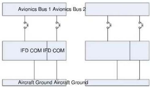
flowchart
graph TD
    A["Avionics Bus 1 Avionics Bus 2"] --> B["IFD COM"]
    A --> C["Aircraft Ground Aircraft Ground"]
    D["AVionics Bus 1 Avionics Bus 2"] --> E["IFD COM"]
    D --> F["Aircraft Ground Aircraft Ground"]
    G["AVionics Bus 1 Avionics Bus 2"] --> H["IFD COM"]
    G --> I["Aircraft Ground Aircraft Ground"]
    J["AVionics Bus 1 Avionics Bus 2"] --> K["IFD COM"]
    J --> L["Aircraft Ground Aircraft Ground"]
    M["AVionics Bus 1 Avionics Bus 2"] --> N["IFD COM"]
    M --> O["Aircraft Ground Aircraft Ground"]
    P["AVionics Bus 1 Avionics Bus 2"] --> Q["IFD COM"]
    P --> R["Aircraft Ground Aircraft Ground"]
    S["AVionics Bus 1 Avionics Bus 2"] --> T["IFD COM"]
    S --> U["Aircraft Ground Aircraft Ground"]
    V["AVionics Bus 1 Avionics Bus 2"] --> W["IFD COM"]
    V --> X["Aircraft Ground Aircraft Ground"]
    Y["AVionics Bus 1 Avionics Bus 2"] --> Z["IFD COM"]
    Y --> AA["Aircraft Ground Aircraft Ground"]

flowchart
graph TD
    A["Avionics Bus"] --> B["IFD COM"]
    A --> C["IFD COM"]
    B --> D["Aircraft Ground"]
    C --> D
    D --> E["Aircraft Ground"]
    F["Ground"] --> G["Aircraft Ground"]
    H["Ground"] --> I["Aircraft Ground"]
Figure 6 Dual IFD Power Distribution (Aircraft <6000 lbs)
Aircraft with a maximum certified gross takeoff weight greater than 6000 pounds must install the dual IFD as shown in Figure 7.
Preferred Alternate

flowchart
graph TD
    A["Avionics Bus 1 Avionics Bus 2"] --> B["IFD COM"]
    A --> C["Aircraft Ground Aircraft Ground"]
    D["AVionics Bus 1 Avionics Bus 2"] --> E["IFD COM"]
    D --> F["Aircraft Ground Aircraft Ground"]
    G["AVionics Bus 1 Avionics Bus 2"] --> H["IFD COM"]
    G --> I["Aircraft Ground Aircraft Ground"]
    J["AVionics Bus 1 Avionics Bus 2"] --> K["IFD COM"]
    J --> L["Aircraft Ground Aircraft Ground"]
    M["AVionics Bus 1 Avionics Bus 2"] --> N["IFD COM"]
    M --> O["Aircraft Ground Aircraft Ground"]
    P["AVionics Bus 1 Avionics Bus 2"] --> Q["IFD COM"]
    P --> R["Aircraft Ground Aircraft Ground"]
    S["AVionics Bus 1 Avionics Bus 2"] --> T["IFD COM"]
    S --> U["Aircraft Ground Aircraft Ground"]
    V["AVionics Bus 1 Avionics Bus 2"] --> W["IFD COM"]
    V --> X["Aircraft Ground Aircraft Ground"]
    Y["AVionics Bus 1 Avionics Bus 2"] --> Z["IFD COM"]
    Y --> AA["Aircraft Ground Aircraft Ground"]
    AB["AVionics Bus 1 Avionics Bus 2"] --> AC["IFD COM"]
    AB --> AD["Aircraft Ground Aircraft Ground"]
    AE["AVionics Bus 1 Avionics Bus 2"] --> AF["IFD COM"]
    AE --> AG["Aircraft Ground Aircraft Ground"]

flowchart
graph TD
    A["Avionics Bus Main Bus"] --> B["IFD COM"]
    A --> C["Aircraft Ground Aircraft Ground"]
    D[" "] --> E[" "]
    D --> F[" "]
    D --> G[" "]
    D --> H[" "]
    D --> I[" "]
    D --> J[" "]
    D --> K[" "]
    D --> L[" "]
    D --> M[" "]
    D --> N[" "]
    D --> O[" "]
    D --> P[" "]
    D --> Q[" "]
    D --> R[" "]
    D --> S[" "]
    D --> T[" "]
    D --> U[" "]
    D --> V[" "]
    D --> W[" "]
    D --> X[" "]
    D --> Y[" "]
    D --> Z[" "]
Figure 7 Dual IFD Power Distribution (Aircraft >6000 lbs)
If installing a 3rd party NAV and/or COM and IFD, connect the IFD as shown in Figure 8.
Preferred Alternate

flowchart
graph TD
    A["Avionics Bus 1"] --> B["IFD COM"]
    C["Aircraft Ground"] --> D["Other COM/NAV"]
    B --> D
    D --> E["Aircraft Ground"]
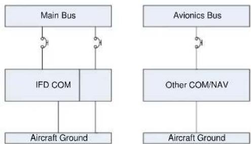
flowchart
graph TD
    A["Main Bus"] --> B["IFD COM"]
    B --> C["Aircraft Ground"]
    D["Avionics Bus"] --> E["Other COM/NAV"]
    E --> F["Aircraft Ground"]
    B --> G["Connection Point 1"]
    B --> H["Connection Point 2"]
Figure 8 Dual NAV/COM Aircraft Bus Installation (Aircraft >6000 lbs)
The installer is responsible for preservation of multiple power busses on the aircraft in accordance with manufacturer's original design and the requirements of 14 CFR Part 23. This includes maintaining electrical power to essential equipment.
4.10 Electrical Load Analysis
Prior to installing the IFD, an electrical load analysis (ELA) must be performed. The aircraft's electrical load should be less than 80% of the total generator output following the IFD installation, reference Section 1.5 for IFD power requirements. Also reference FAA AC 43.13-2B Paragraph 208 for more information on performing an aircraft electrical load analysis.
The purpose of the ELA is to show compliance to 14 CFR §23.1351 and §23.1353 (h).
4.11 Low Power Behaviors
The IFD can accept input power ranging from 9VDC to 33VDC but has the following low power behaviors.
Functions are restored if the IFD input voltage rises 1VDC above threshold voltage for 1 second.
| Input Voltage Level | Behavior |
| 19.9VDC | 16W VHF radio output power reduces to 10W * |
| ≥18VDC | High power USB charging (dedicated charging port drawing 2.1A). |
| <18VDC | USB port drops from High power USB charging to Low power USB charging (dedicated charging port drawing 1.0A). |
| 12.75VDC | USB port is turned off (no charging available). |
| 11.5VDC | Bezel and LCD display dimmed down to 25% and a yellow “Low Volts” CAS message is presented. |
| 10.9VDC | VHF radio output power reduces to 6W * |
| 10.0VDC | VHF radio output power reduces to 4W * |
| 9VDC | Start a 60 second power down sequence and a red “Low Volts Off insec” CAS message is presented. With 5 seconds to go until power down, the full power down message is overlaid in the middle of the display. |
*N/A for IFD510/545/410 and Atlas FMS Only units
Table 47 IFD Low Power Behavior
5. Mechanical Installation
This section will describe the physical mounting of the IFD or Atlas in the aircraft.
Aircraft installing an IFD for VFR use only, as defined in Section 2.1.1, can install the IFD unit in any location easily accessible to the pilot. However, the IFD installation must not introduce any new hazards. All other installations must follow the guidance below.
5.1 Equipment Location – New Installations
If the IFD is used for IFR navigation, course deviation information and navigation annunciation must be installed in the Pilot's Field of View (FOV). The FAA has provided clarification regarding the intent of TSO-C146 and acceptable source annunciation location, navigation annunciation, and FOV requirements on similar products in the past. Therefore, the installation data as follows must be followed to maintain compliance with the STC. Otherwise, additional installation approval will be required.
Aircraft requiring two pilots must have this annunciation at each pilot station or unobstructed view of the IFD display. The IFD should be located in a position easily reached by both pilots.
5.1.1 Determining the IFD Field of View
In determining the requirement for remote annunciators, the installer must determine if the IFD location falls within the required pilot field of view. The IFD navigation source selection indication ("GPS" or "VLOC") required field of view is ± 30^ or 13.8'' horizontally from the center of the attitude indicator, or centerline of the pilot's seat/yoke. The navigation and TAWS (if enabled) annunciation field of view is approximately ± 35^ or 16.8'' horizontally from the center of the attitude indicator. Both of these angles and distances are determined with the pilot seated at a minimum of 24'' from the instrument panel. For aircraft without a basic instrument 'T' or an offset control yoke/control, use the center of the pilot's seat as the primary view centerline.
The vertical field of view will be from the top of the instrument panel to the portion of the instrument panel that is immediately below the basic 'T' instruments, reference
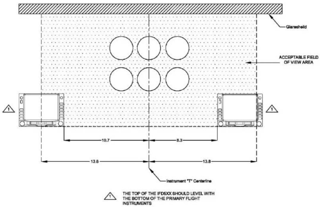
Figure 9. Note, if the existing type certified HSI/CDI/PFD is lower than the basic 'T', use that as the lower limit.

Figure 9 below indicates the acceptable field of view for the IFD5XX/4XX. If the IFD5XX/4XX can be installed in this area, remote navigation annunciation is not required. If the IFD5XX/4XX cannot be installed within the acceptable field of view, the installation must have navigation annunciations installed per Section 5.1.2.
Note: The dimensions shown in

Figure 9 and Figure 10 for the IFD5XX also apply to the IFD4XX.
Note: Atlas units mounted in center console positions will fall outside of the required field of view for annunciations. Panel mounted annunciators are required in the prescribed field of view.
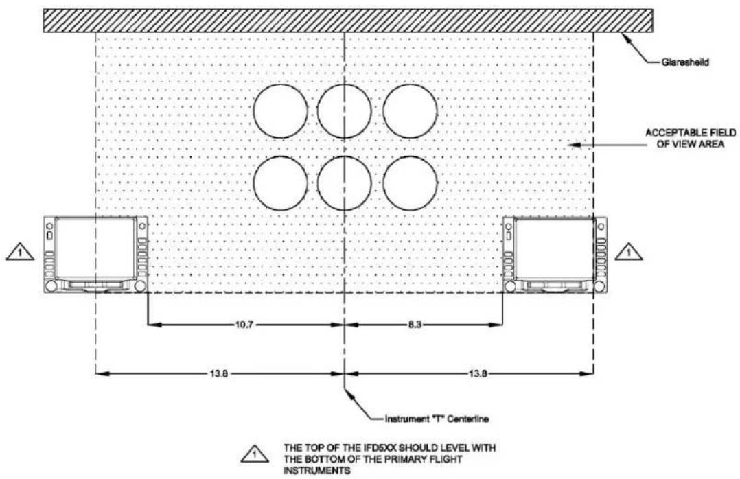
Figure 9 Field of View
5.1.2 Navigation and TAWS (if enabled) Annunciation
The navigation and TAWS (if enabled) annunciations listed in Table 48 must be installed in the Pilot's Field of view. This may be accomplished in several ways. The following are acceptable:
- Use Navigation Annunciation on an existing Primary Flight Display or Horizontal Situation Indicator located in the Pilot's primary field of view. CDI/HSI indicators with navigation annunciation is acceptable (e.g. GI 106, MD200-306, or similar). The CDI/HSI must be located within the primary field of view.
If the IFD5XX/4XX is located within the acceptable field of view, as shown in

• Figure 9, external annunciation is not needed
- Install external annunciation lights in the acceptable field of view, as shown in Figure 10.
The IFD should have the following annunciation within the Pilot's Field of View when installing an external annunciator:
| Navigation Annunciation Type |
| VLOC Annunciate‡ |
| GPS Annunciate‡ |
| OBS Annunciate (optional) |
| Waypoint Annunciate |
| Terminal Annunciate |
| Approach Annunciate |
| Message Annunciate |
| LOI, INTEG, or INTG Annunciate |
| Terrain N/A ** |
| Terrain Pull Up** |
| Terrain Caution** |
| TAWS Inhibit** |
Table 48 Navigation and TAWS Annunciation
^ Must be located ±30^ or 13.856", see Section 5.1.1
** w/ Fixed Wing TAWS Enabled
The navigation and/or TAWS annunciators should be readable under all lighting conditions. The annunciators must be able to be tested prior to flight. The field of view in
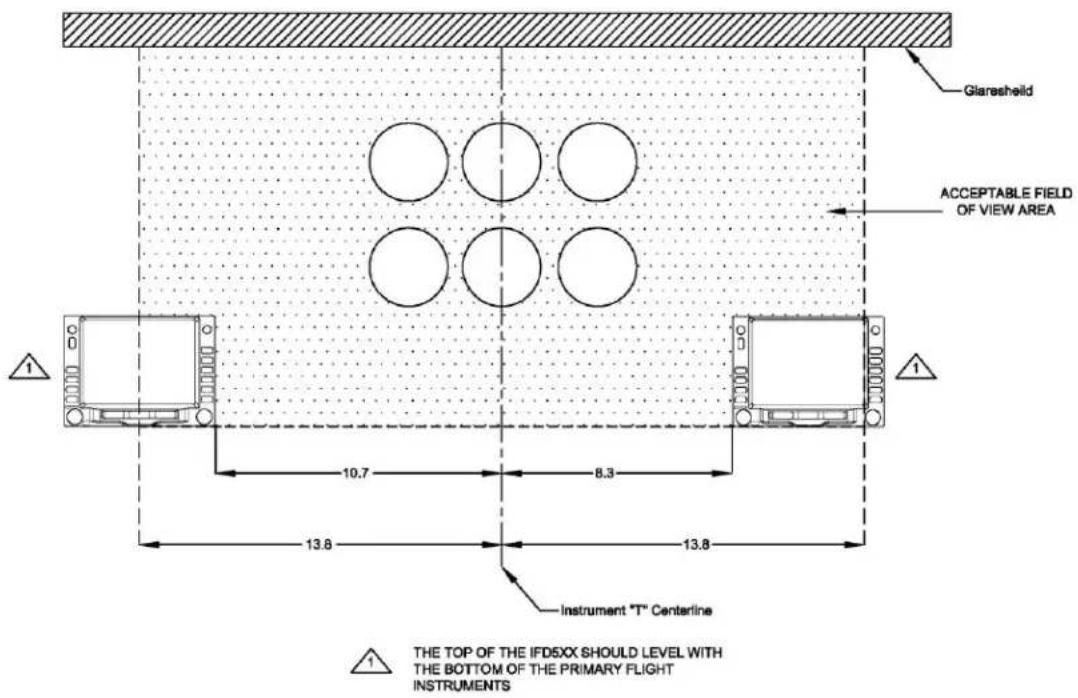
Figure 9 is based on ± 35^ from the Instrument "T" centerline at 24" aft of the panel.
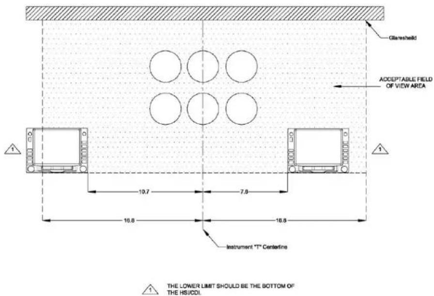
Figure 10 Navigation and TAWS(if enabled) Annunciation Field of View
5.1.3 Course Deviation Indicator
The course deviation information must be located in the Pilot's Primary Field of view if the IFD is used for IFR navigation. Installation of a CDI/HSI requires a separate installation approval.
5.1.4 Instrument Panel Cutout
The IFD5XX and IFD4XX tray is designed to be installed on the backside of the instrument panel. The instrument panel requires either a 6.320" x 4.600" or 6.320" x 2.70" hole for the IFD5XX or IFD4XX respectively. If the instrument panel in the aircraft is considered primary structure, additional installation approval will be required for the instrument panel cutout. The installer is responsible to ensure the structural aspects of this installation meet the requirements of AC 43.13-2B, Chapter 11, Paragraph 1104(a).
5.1.5 Requirements for Tray Installation
The Avidyne Tray must be installed in the aircraft as described below in order to satisfy the structural requirements for the STC. Deviations to these requirements will require separate approval.
- Rear Tray Support (Instrument Panel)
a. The existing instrument panel must be fabricated from 2024-T3 aluminum with a minimum thickness of 0.050" (Note: equivalent or stronger is acceptable). The tray brackets must be fabricated from 3/4" x 3/4" x 1/16" 2024-T3 aluminum angle for mounting the tray, as shown in Figure C - 1 and Figure C - 2.
b. If new components are fabricated, the fabrication methods must follow the requirements of FAA Advisory Circular 43.13-1B, Chapter 4 for general airframe fabrication criteria, including hole tolerances, edge distances, rivet spacing, and corrosion protection, and Advisory Circular 43.13-2B Chapters 2 and 11 for structural adequacy.
- Forward Tray Support
a. The Avidyne Tray must have forward support brackets, reference Figure C - 1 or Figure C - 2. The forward support brace must be 0.032" 5052-H32 aluminum. (Note: equivalent or stronger is acceptable)
b. If new forward support brackets are fabricated, the fabrication methods must follow the requirements of either Figure C - 1 or Figure C - 2, FAA Advisory Circular 43.13-1B, Chapter 4 for general airframe fabrication criteria, including hole tolerances, edge distances, rivet spacing, and corrosion protection, and Advisory Circular 43.13-2B, Chapters 2 and 11 for structural adequacy.
The IFD5XX tray should be installed using six #6-32 100° flat head screws and self-locking nuts. The IFD4XX tray should be installed using four #6-32 100° flat head screws and self-locking nuts.
5.2 Equipment Location - Replacement Unit
If the IFD is being installed as replacement unit on a previously approved IFR installation, the existing installation location is acceptable and does not require any changes.
5.3 Equipment Location - Atlas Unit
Utilizing an existing dzus rail console, verify that the console structure has not been altered or modified and meets the type design of the installation aircraft. Assure adequate depth is available to accommodate the Atlas unit as well as connectors and associated wire bundles. The installer must determine the airworthiness of the location of any dzus rail mounted equipment that is moved when installing the Atlas unit to meet the required angle of regard for the Atlas display. The captive quarter-turn fasteners in the Atlas unit are utilized to fasten the IFD to the dzus rail structure.
5.4 Angle of Regard
The IFD5XX/4XX should be mounted in a location where the viewing angle of the display does not exceed the following angles: Note: the reference plane for these measurements is the unit itself:
• From the Left: 45°
• From the Right: 45°
• From the Top: 35°
• From the Bottom: 15°
The Atlas should be mounted in a location where the viewing angle of the display does not exceed the following angles:
• From the Left: 45°
• From the Right: 45°
• From the Top: 15°
• From the Bottom: 35°
Note: The Atlas display viewing angles are designed to accommodate a typical center console installation. Angled consoles or console transitions may not meet the stated angle of regard requirements above. Instrument panel installations are not acceptable.
5.5 Unit Installation/Removal
5.5.1 IFD IFD5XX/4XX Installation/Removal
The IFD5XX/4XX should be installed using 3/32-inch hex drive tool. The hex drive is inserted into the hole in the front bezel.
5.5.2 Atlas Installation/Removal
Remove equipment to be replaced from the center console per the instructions of the existing equipment manufacturer. Inspect the center console support structure to ensure no alterations or modifications have been made and it meets type design. Ensure the Avidyne Dzus fastener pattern is compatible with the existing Dzus rails. If evidence of alteration is found, or if Dzus rails are not compatible, separate approval is required.
Record the weight of all equipment removed from the center console Dzus rails, including fasteners and electrical connectors. Verify the weight of the removed equipment exceeds the Atlas installed weight shown in Table 25. If weight of removed equipment is less than the Atlas installed weight, separate approval is required.
Install ATLAS on existing Dzus rails or rack by engaging the 4 Dzus quarter turn fasteners with an appropriately sized flat blade tool.
5.6 Internal Cooling
The IFDXXX units have several internal fans and heat sinks as part of their basic design. The IFDXXX units have intake and exhaust vents on the left and right sides of the chassis with cut outs in the tray to facilitate venting. The left and right sides of the front bezel have intake louvers to help pull ambient cockpit air through the unit. The IFDXXX will benefit from keeping these vents clear of all obstructions.
The Atlas units have intake and exhaust vents on the top and bottom of the chassis and a few louvers on the back of the head unit.
While not necessary, if installation flexibility permits, the units will benefit from these intake and exhaust vents remaining as clear as feasible. In some cases failure to do so can cause an over-temp condition.
5.7 External Cooling
The IFD does not require external cooling; however, additional cooling may prolong product life. A 5/8" diameter air fitting is provided in the rear of the IFD mounting tray, if forced air cooling is installed.
IFD installations in a tightly packed avionics stack should consider installing an electric avionics cooling fan. As a minimum, plan to leave space for clear intake and exhaust venting when able. If a fan is installed, ensure the intake air flow to the fan is not located near the exhaust of other fans or near other hot equipment.
In the event the system feels excessively hot or if an Overtemp Caution Advisory System message is presented on the display, there are some diagnostic tools provided in the IFD to assist in finding more optimal cooling installations. In Maintenance Mode, select the “Status” tab along the bottom edge of the display and then press the “Info” Line Select Key as needed until “Temps” is displayed. Note the hottest source(s) on that page and supply that information to Avidyne Technical Support to include both the source and the associated temperature for follow-on guidance. If a Red CAS message is displayed at an time with the warning, “UNIT OVERTEMP UNIT UNRELIABLE” the IFD must return to Avidyne for servicing.
The metal bezel of the IFD is intentionally designed to radiate heat away from the internal components and out of the unit. This can have the effect of a bezel that may be warm to the touch. This is considered normal. Note that the rubber bezel buttons will not conduct this heat and should not be warm. This condition will be more noticeable on hot days or during long ground runs.
5.8 Electrical Bonding
The electrical bonding between the IFD5XX/IFD4XX tray or the Atlas rear ground screws and aircraft ground should be ≤ 10 milliohm.
5.9 Aircraft Considerations
Installing wires or antennas on a pressurized aircraft, composite aircraft, or with an aircraft certification basis of Amendment 23-45 or later is beyond the scope of this manual and requires additional installation approval, unless the aircraft model is listed on the STC AML.
5.10 Weight and Balance
After installing the IFD, the aircraft's weight and balance must be updated after installation is complete.
For those installations where an IFD5XX/4XX is replacing a GNS530/430 (any variant), since the IFD is within 5% of the weight of the removed GNS530/430 (less than 1 pound difference), no new weight and balance must actually be performed according to AC 43.13-1B Change 1 Acceptable Methods, Techniques, and Practices Aircraft Inspection and Repair (Chapter 10) and AC 120-27E Aircraft Weight and Balance Control.
5.11 Compass Safe Distance
The IFD should be installed 12" or more away from the aircraft's magnetic compass. Perform an aircraft compass swing/calibration after completing the IFD installation.
Note: The 12" minimum distance is a TSO-driven value that is designed to ensure the unit will have no impact on the aircraft compass. If an installation is made where this distance is less than 12", then a compass swing/calibration must be accomplished after completing the IFD installation.
6. System Installation
The following section will describe interfacing the IFD to various other avionics and aircraft equipment.
6.1 Pin Function List
The following Section Lists the Pin function for each connector.
6.1.1 P1001 Main Connector
| Pin | Description | Signal Type |
| 1 | VLOC Annunciate | Output |
| 2 | GPS Annunciate | Output |
| 3 | Waypoint Annunciate | Output |
| 4 | Terminal Annunciate | Output |
| 5 | Approach Annunciate | Output |
| 6 | Message Annunciate | Output |
| 7 | OBS Annunciate | Output |
| 8 | Weight on Wheels (WOW) Output | Output |
| 9 | Integrity Annunciate | Output |
| 10 | Annunciate D | Output |
| 11 | Annunciate E | Output |
| 12 | Reserved | Output |
| 13 | GPS Select | Output |
| 14 | ILS/GPS Annunciate (Approach) | Output |
| 15 | Aircraft Power 2 | Input |
| 16 | Time Mark Out | Output |
| 17 | Main Lateral Superflag | Output |
| 18 | Main Vertical Superflag | Output |
| 19 | Aircraft Power 1 | Input |
| 20 | Aircraft Power 1 | Input |
| 21 | Main +Left | Output |
| 22 | Main +Right (1.65V COM) | Output |
| 23 | Main Lat +Flag | Output |
| 24 | Main Lat -Flag (GND) | - |
| 25 | Main +To (1.65V Common) | Output |
| 26 | Main +From | Output |
| 27 | Main +Up (1.65V Common) | Output |
| 28 | Main +Down | Output |
| 29 | Main Vertical +Flag | Output |
| 30 | Main Vertical -Flag (GND) | - |
| 31 | Main OBS Rotor C | Output |
| 32 | Main OBS Rotor H(GND) | - |
| 33 | Main OBS Stator D | Input |
| 34 | Main OBS Stator E (2.5V Common OBS) | Output |
| 35 | Main OBS Stator F | Input |
| 36 | Main OBS Stator G (2.5V Common OBS) | Output |
| 37 | Audio 1 HI (Alert audio) | Output |
| 38 | Audio 1 LO (Alert audio) | Output |
| 39 | LTG Bus HI | Input |
| 40 | LTG Bus LO (GND) | Input |
| 41 | GPS RS232 Out 3 | Output |
| 42 | GPS RS232 In 3 | Input |
| 43 | Main OBI Clock | Output |
| 44 | Main OBI Data | Output |
| 45 | Main OBI Sync | Output |
| 46 | GPS Arinc-429 Out 1A | Output |
| 47 | GPS Arinc-429 Out 1B | Output |
| 48 | GPS Arinc-429 In 1 A | Input |
| 49 | GPS Arinc-429 In 1 B | Input |
| 50 | GPS Arinc-429 In 2 A | Input |
| 51 | GPS Arinc-429 In 2 B | Input |
| 52 | Audio 2 HI | Output |
| 53 | Audio 2 LO | Output |
| 54 | GPS RS232 Out 4 | Output |
| 55 | GPS RS232 In 4 | Input |
| 56 | GPS RS232 Out 1 | Output |
| 57 | GPS RS232 In 1 | Input |
| 58 | GPS RS232 Out 2 | Output |
| 59 | GPS RS232 In 2 | Input |
| 60 | Altitude Common (GND) | - |
| 61 | Altitude C4 | Input |
| 62 | Altitude C2 | Input |
| 63 | Altitude C1 | Input |
| 64 | Altitude B4 | Input |
| 65 | Altitude B2 | Input |
| 66 | Altitude B1 | Input |
| 67 | Altitude A4 | Input |
| 68 | Altitude A2 | Input |
| 69 | Altitude A1 | Input |
| 70 | Altitude D4 / Weight on Wheels Input (Helicopter use) | Input |
| 71 | OBS Mode Select | Input |
| 72 | Aircraft Power 2 | Input |
| 73 | CDI Source Select | Input |
| 74 | COM Remote Recall Forward | Input |
| 75 | COM Remote Recall Reverse | Input |
| 76 | LTG BUS 2 HI | Input |
| 77 | Aircraft GND | - |
| 78 | Aircraft GND | - |
Table 49 P1001 Pin Description
For fixed-wing aircraft, the IFD5XX/4XX and Atlas use GPS velocity and AGL altitude to determine In-Air/On-Ground state. The WOW transition output logic is on P1001 Pin 8
On-Ground = 30kts and below
In-Air = 50kts and above
6.1.2 P1002 Communication Connector
Note: This connector is not used in the IFD510/545/410 or Atlas FMS Only units
| Pins | Description | Signal Type |
| 1 | Reserved | - |
| 2 | Ethernet 1 TX+ | Output |
| 3 | Ethernet 1 TX- | Output |
| 4 | COM Microphone Key | Input |
| 5 | Intercom Microphone Audio HI | Input |
| 6 | COM Microphone Audio HI | Input |
| 7 | COM Audio HI | Output |
| 8 | Ethernet 1 RX+ | Input |
| 9 | Ethernet 1 RX- | Input |
| 10 | Synchro X | Input |
| 11 | Aircraft Power | Input |
| 12 | Aircraft Power | Input |
| 13 | Synchro Reference Signal + | Input |
| 14 | Transmit Interlock (Unused) | Input |
| 15 | COM Remote Transfer | Input |
| 16 | Reserved | - |
| 17 | Intercom Microphone Audio LO | Input |
| 18 | COM Microphone Audio LO | Input |
| 19 | COM Audio LO | Output |
| 20 | Reserved | - |
| 21 | Aircraft GND | - |
| 22 | Aircraft GND | - |
| 23 | Synchro Y | Input |
| 24 | Synchro Z | Input |
| 25 | Synchro Reference Signal - | Input |
Table 50 P1002 Pin Description
6.1.3 P1006 Navigation Connector
Note: This connector is not used in the IFD510/545/410
| Pins | Description | Signal |
| 1 | VOR/LOC +To | Output |
| 2 | VOR/LOC +From (VOR/LOC 2.5V Common) | Output |
| 3 | VOR/LOC +Flag | Output |
| 4 | VOR/LOC -Flag (VOR/LOC 2.5V Common) | Output |
| 5 | VOR/LOC +Left | Output |
| 6 | VOR/LOC +Right (VOR/LOC 2.5V Common) | Output |
| 7 | Com Monitor Audio HI | Output |
| 8 | VOR/LOC Composite Out | Output |
| 9 | VOR OBS Rotor C | Output |
| 10 | VOR OBS Rotor H (GND) | - |
| 11 | VOR OBS Stator E/G (VOR/LOC 2.5V Common) | Output |
| 12 | VOR OBS Stator F | Input |
| 13 | VOR OBS Stator D | Input |
| 14 | Parallel DME - 8MHz | Output |
| 15 | VOR/LOC Superflag | Output |
| 16 | VOR/ILS Audio HI | Output |
| 17 | VOR/ILS Audio LO | Output |
| 18 | Serial DME - Clock | Output |
| 19 | Serial DME - Data | Output |
| 20 | Ser DME-Chan REQ/PAR DME - 4MHz | Input/output |
| 21 | Ser DME-RNAV Mode/PAR DME - 2MHz | Input/output |
| 22 | DME Common | Input |
| 23** | VOR/ILS Arinc-429 Out B | Output |
| 24** | VOR/ILS Arinc-429 Out A | Output |
| 25 | VOR OBI Clock | Output |
| 26 | VOR OBI Sync | Output |
| 27 | VOR OBI Data | Output |
| 28 | VLOC Remote Transfer | Input |
| 29 | ILS Energize | Output |
| 30 | Glideslope +Flag | Output |
| 31 | Glideslope +Down/-Flag (Glideslope 2.5V Common) | Output |
| 32 | Glideslope +Up | Output |
| 33 | Parallel DME - 1MHz | Output |
| 34 | Com Monitor Audio LO | Output |
| 35 | VOR/ILS Arinc-429 In B | Input |
| 36 | VOR/ILS Arinc-429 In A | Input |
| 37 | Parallel DME - 800KHz | Output |
| 38 | Glideslope Superflag | Output |
| 39 | Parallel DME - 400KHz | Output |
| 40 | Parallel DME - 200KHz | Output |
| 41 | Aircraft GND | - |
| 42 | Parallel DME - 100KHz | Output |
| 43 | Parallel DME - 50KHz | Output |
| 44 | Aircraft Power | Input |
** GLAS Enable only
Table 51 P1006 Pin Description
6.1.4 P1050 Additional I/O Connector
Please note: This connector is not available on the IFD4XX.
| Pins | Description | Signal |
| 1 | TAWS Inhibit IN | Input |
| 2 | TAWS Audio Inhibit IN | Input |
| 3 | HTAWS Reduced Protection Mode | Input |
| 4 | HTAWS Aural Suppression | Input |
| 5 | Spare Input 2 | Input |
| 6 | Spare Input 1 | Input |
| 7 | Reserved | - |
| 8 | Reserved | - |
| 9 | Terrain Not Available Annunciate | Output |
| 10 | Terrain Warning Annunciate | Output |
| 11 | Terrain Caution Annunciate | Output |
| 12 | TAWS Inhibit Annunciate | Output |
| 13 | HTAWS Reduced Protection Annunciate | Output |
| 14 | Spare Annunciate 1 | Output |
| 15 | TAWS Audio Active Out | Output |
| 16 | Reserved | - |
| 17-21* | Ground | - |
| 22-39* | NO CONNECT | - |
| 40 | ARINC 453 RX+ | Input |
| 41 | ARINC 453 RX - | Input |
| 42 | GPS ARINC-429 Out 2A | Output |
| 43 | GPS ARINC-429 Out 2B | Output |
| 44 | VOR/ILS ARINC 429 OUT 3A** | Output |
| 45 | VOR/ILS ARINC 429 OUT 3B** | Output |
| 46-59* | NO CONNECT | - |
| 60 | RS232 Out 5 | Output |
| 61 | RS232 IN 5 | Input |
| 62 | RS232 Out 6 | Output |
| 63 | RS232 IN 6 | Input |
| 64 | Ground | - |
| 65-76 | NO CONNECT | - |
| 77 | RS170 Video IN | Input |
| 78 | Ground | Input |
*Note: Atlas only - P1050 connector is keyed blocking pins 19, 20, 32, 33, 46 and 47 for connector orientation purposes.
Table 52 P1050 Pin Description
** GLAS Enable only
6.1.5 Altitude Gray Code
Altitude Gray code input is connected on the following pins:
| Description | Connector | Pin | Signal Type |
| Altitude D4 | P1001 | 70 | Input |
| Altitude A1 | P1001 | 69 | Input |
| Altitude A2 | P1001 | 68 | Input |
| Altitude A4 | P1001 | 67 | Input |
| Altitude B1 | P1001 | 66 | Input |
| Altitude B2 | P1001 | 65 | Input |
| Altitude B4 | P1001 | 64 | Input |
| Altitude C1 | P1001 | 63 | Input |
| Altitude C2 | P1001 | 62 | Input |
| Altitude C4 | P1001 | 61 | Input |
| Altitude Common | P1001 | 60 | Input |
Table 53 Altitude Gray Code Description
NOTE: Some transponders and altitude encoders do not have internal isolation diodes to prevent the unit from pulling the encoder lines to ground when the unit is off. These units will require the installation of a diode into harness for each encoder line.
6.1.6 Heading Input
Note: This section is N/A for the IFD510/545/410 and Atlas FMS Only units.
The IFD can accept a 3-wire ARINC 407 Synchro heading input on the following connectors and pins:
| Description | Connector | Pin | Signal Type |
| Synchro X | P1002 | 10 | Input |
| Synchro Reference Signal + (26VAC 400 Hz) | P1002 | 13 | Input |
| Synchro Y | P1002 | 23 | Input |
| Synchro Z | P1002 | 24 | Input |
| Synchro Reference Signal - (GND) | P1002 | 25 | Input |
Table 54 Synchro Heading Input
6.1.7 Main Course Deviation Indicator Output
The main indicator displays both lateral and vertical deviations, TO/From, and Flag indications from the NAV and GPS receivers.
6.1.7.1 Lateral/Vertical Deviations
The lateral and vertical deviations are on the following connector and pins:
| Description | Connector | Pin | Signal Type |
| Main +Left | P1001 | 21 | Output |
| Main +Right | P1001 | 22 | Output |
| Main +Up | P1001 | 27 | Output |
| Main +Down | P1001 | 28 | Output |
Table 55 Main Course Deviation Output
6.1.7.2 TO/FROM Indication Flag
The To/From Flag indication flags are on the following connector and pins:
| Description | Connector | Pin | Signal Type |
| Main +To | P1001 | 25 | Output |
| Main +From | P1001 | 26 | Output |
Table 56 Main TO/From Flag Output
6.1.7.3 Navigation Flags
The Navigation Flags is on the following connector and pins:
| Description | Connector | Pin | Signal Type |
| Main Lateral +Flag | P1001 | 23 | Output |
| Main Lateral -Flag | P1001 | 24 | Output |
| Main Vertical +Flag | P1001 | 29 | Output |
| Main Vertical -Flag | P1001 | 30 | Output |
Table 57 Main Navigation Flag Output
6.1.7.4 Navigation Superflags
The Navigation Superflags is on the following connector and pins:
| Description | Connector | Pin | Signal Type |
| Main Lateral Super Flag | P1001 | 17 | Output |
| Main Vertical Super Flag | P1001 | 18 | Output |
Table 58 Main Navigation Superflag Output
Superflag outputs system voltage when valid and <.25 VDC when not valid. This output is capable of driving 500mA at 28 VDC or 250mA at 14 VDC. Power is from P1006 pin 44
6.1.7.5 OBS
The OBS is on the following connector and pins:
| Description | Connector | Pin | Signal Type |
| Main OBS Rotor C | P1001 | 31 | Output |
| Main OBS Rotor (Ground) | P1001 | 32 | Output |
| Main OBS Stator D | P1001 | 33 | Input |
| Main OBS Stator E | P1001 | 34 | Output |
| Main OBS Stator F | P1001 | 35 | Input |
| Main OBS Stator G | P1001 | 36 | Output |
Table 59 Main OBS Output
6.1.7.6 Annunciators Electrical Output
| Description | Connector | Pin | Signal Type |
| VLOC Annunciate | P1001 | 1 | Output |
| GPS Annunciate | P1001 | 2 | Output |
| Waypoint Annunciate | P1001 | 3 | Output |
| Terminal Annunciate | P1001 | 4 | Output |
| Approach Annunciate | P1001 | 5 | Output |
| Message Annunciate | P1001 | 6 | Output |
| OBS Annunciate | P1001 | 7 | Output |
| Integrity Annunciate | P1001 | 9 | Output |
| LNAV GPS Select | P1001 | 13 | Output |
| ILS/GPS Approach | P1001 | 14 | Output |
Table 60 Annunciator Output
All outputs sink up to 500 mA when activated.
Some legacy autopilots require a “delayed ILS” discrete input. This function is used to prevent an autopilot from engaging too quickly upon glideslope capture. The output prevents the autopilot from an immediately pitch up or down to center the glideslope needle.
Rockwell Collins VIR-30/32/432/433 VHF navigation sensors have this discrete output. It is incorporated to switch an external relay in the flight guidance system when an ILS frequency is selected, otherwise it is an open.
When replacing one of the radios listed above, it is imperative to determine if the delayed ILS output is being used with the installed autopilot.
To accomplish this function using an IFD or Atlas:
ILS/GPS Approach: P1001 Pin 14 will replace this existing output.
ILS Approach: P1006 Pin 29 for VHF approach sensor approach operations only (see Table 51).
6.1.7.7 Switch Inputs
| Description | Connector | Pin | Signal Type |
| OBS Mode Select | P1001 | 71 | Input |
| CDI Source Select | P1001 | 73 | Input |
Table 61 Switch Inputs
The inputs are considered active if voltage to ground <1.9V or resistance to ground <375 . These inputs are considered inactive if voltage to ground is 11-33 VDC.
6.1.7.8 Time Mark Out
| Description | Connector | Pin | Signal Type |
| Time Mark Out | P1001 | 16 | Output |
Table 62 Time Mark Output
Outputs a 1ms ± 1μs wide pulse once every 1.0 Second ± 2 ms. Output sources 1 mA at >3.8 V and sinking 1 mA at less than 0.4 V.
6.1.8 Serial Data
6.1.8.1 RS-232
| Description | Connector | Pin | Signal Type |
| RS-232 Output 1 | P1001 | 56 | Output |
| RS-232 Input 1 | P1001 | 57 | Input |
| RS-232 Output 2 | P1001 | 58 | Output |
| RS-232 Input 2 | P1001 | 59 | Input |
| RS-232 Output 3 * | P1001 | 41 | Output |
| RS-232 Input 3 * | P1001 | 42 | Input |
| RS-232 Output 4 | P1001 | 54 | Output |
| RS-232 Input 4 | P1001 | 55 | Input |
| RS-232 Output 5‡ | P1050 | 60 | Output |
| RS-232 Input 5‡ | P1050 | 61 | Input |
| RS-232 Output 6‡ | P1050 | 62 | Output |
| RS-232 Input 6‡ | P1050 | 63 | Input |
Table 63 RS-232 Input / Output
*RS-232 Port 3 Output and Input should only be used for cross-synch of two IFDs. In single IFD installations leave RS-232 Port 3 Output and Input set to Off.
‡IFD5XX and Atlas Only
6.1.9 ARINC 429
| Description | Connector | Pin | Signal Type |
| GPS ARINC 429 OUT 1A | P1001 | 46 | Output |
| GPS ARINC 429 OUT 1B | P1001 | 47 | Output |
| GPS ARINC 429 IN 1 A | P1001 | 48 | Input |
| GPS ARINC 429 IN 1 B | P1001 | 49 | Input |
| GPS ARINC 429 IN 2 A | P1001 | 50 | Input |
| GPS ARINC 429 IN 2 B | P1001 | 51 | Input |
| VOR/ILS ARINC 429 OUT A | P1006 | 24 | Output |
| VOR/ILS ARINC 429 OUT B | P1006 | 23 | Output |
| VOR/ILS ARINC 429 IN A | P1006 | 36 | Input |
| VOR/ILS ARINC 429 IN B | P1006 | 35 | Input |
| GPS ARINC 429 OUT 2A* | P1050* | 42 | Output |
| GPS ARINC 429 OUT 2B* | P1050* | 43 | Output |
| VOR/ILS ARINC 429 OUT 3A** | P1050** | 44 | Output |
| VOR/ILS ARINC 429 OUT 3B** | P1050** | 45 | Output |
Table 64 ARINC 429 Input / Output
* IFD5XX and Atlas only, ** GLAS Enabled only
6.1.9.1 GPS ARINC Output
The data output on the GPS ARINC out port depends on the configuration of the unit. Below is a list of configurations and label outputs for each:
- ARINC 429
- GAMA 429
- GAMA 429 Graphics
- GAMA 429 Graphics w/Int
- GAMA 429 Pro Line 21
- GAMA 429 Sextant
- GAMA 429 Bendix King
- GAMA 429 Thales
- GAMA 429 Non-Standard
- ARINC 743A
- ARINC 743A+
- Becker BXT Ctl
**Note: Labels 102 (Selected Altitude), 117, 126, 322 and 327 are enabled or disabled via a separate Mx setting
Table 65 GPS ARINC Output
6.1.9.2 VHF ARINC Output
N/A for IFD410, IFD510, IFD545, and Atlas FMS Only units
| Label Number | Parameter Name |
| 034G | VOR/ILS Frequency |
| 035G | DME Frequency |
| 100G | Selected Course # 1 |
| 173 | Localizer Deviation |
| 174 | Glideslope Deviation |
| 222 | VOR Omni bearing |
| 371G | Specific Equipment |
| 377 | Equipment Hex ID Code |
Table 66 VHF ARINC Output
6.1.9.3 Onboard Radar ARINC Output
When configured, a Radar ARINC 429 channel shall transmit the following data:
IFD Series Installation Manual
| Label Number | Parameter Name |
| 270 | Radar Mode, Tilt, and Gain |
| 271 | Roll-Trim, Range |
| 273 | Vertical Profile |
| Label Number | Parameter Name |
| 275 | Display Mode |
| 324 | Pitch angle (Degrees), Stabilization Not Supported |
| 325 | Roll Angle (Degrees), Stabilization Not Supported |
Table 67 Radar ARINC Output
6.1.10 ARINC 453
| Description | Connector | Pin | Signal Type |
| ARINC 453 RX + | P1050 | 40 | Input |
| ARINC 453 RX - | P1050 | 41 | Input |
Table 68 ARINC 453 Input
6.1.11 RS170 Video
| Description | Connector | Pin | Signal Type |
| RS170 Video In High | P1050 | 77 | Input |
| RS170 Video In Low | P1050 | 78 | Input |
Table 69 RS170 Video Input
6.1.12 Com/VOR/ILS Audio Electrical Characteristics
Note: This section is N/A for IFD510/545/410
6.1.12.1 Com Microphone Key
| Description | Connector | Pin | Signal Type |
| COM MIC Key | P1002 | 4 | Input |
Table 70 VHF Communication Microphone Key
This input is active if either the voltage to ground <1.9V or the resistance to ground is <375Ω. This input is considered inactive if the voltage to ground is 11-33 VDC.
Activating the COM MIC Key will cause the transmitter to transmit the audio on the COM MIC Audio HI.
6.1.12.2 Com Microphone Audio, INTERCOM Microphone Audio
| Description | Connector | Pin | Signal Type |
| COM MIC Audio HI | P1002 | 6 | Input |
| Description | Connector | Pin | Signal Type |
| COM MIC Audio LO | P1002 | 18 | Input |
| INTERCOM MIC HI | P1002 | 5 | Input |
| INTERCOM MIC LO | P1002 | 17 | Input |
Table 71 VHF Communication Audio 520Ω input impedance, supply 9V via 620Ω.
6.1.12.3 Com Audio, VOR/ILS Audio
| Description | Connector | Pin | Signal Type |
| Com Audio HI | P1002 | 7 | Output |
| Com Audio LO | P1002 | 19 | Output |
| VOR/ILS Audio HI | P1006 | 16 | Output |
| VOR/ILS Audio LO | P1006 | 17 | Output |
Table 72 VHF Communication and Navigation Audio Output
Each supply 65mW into 150Ω. They are balanced outputs and LO output must be connected.
6.1.12.4 Discrete Inputs
| Description | Connector | Pin | Signal Type |
| Transmit Interlock (Unused) | P1002 | 14 | Input |
| Com Remote Transfer | P1002 | 15 | Input |
| VLOC Remote Transfer | P1006 | 28 | Input |
| Com Remote Recall, Forward | P1001 | 74 | Input |
| Com Remote Recall, Reverse | P1001 | 75 | Input |
Table 73 VHF Communication and Navigation Switch Inputs
This input is active if either the voltage to ground <1.9V or the resistance to ground is <375Ω. This input is considered inactive if the voltage to ground is 11-33 VDC.
COM Remote Transfer and VLOC Remote Transfer are momentary inputs. Momentarily depressing the VLOC or Com Remote transfer button toggles the active and #1 standby frequencies. Momentarily depressing the COM Remote Recall button inserts the next frequency in the Com preset list into the #1 standby slot.
6.1.12.5 Standby Com Monitor
| Description | Connector | Pin | Signal Type |
| Com Monitor Audio HI | P1006 | 7 | Output |
| Com Monitor Audio LO | P1006 | 34 | Output |
Table 74 Standby Communication Output
This optional signal use can be used with audio panels that have a means of selecting the #1 standby com audio (e.g. Avidyne AMX240).
6.1.13 VOR/ILS Indicator Electrical Characteristics
Note: This section is N/A for IFD510/545/410 and Atlas FMS Only units.
6.1.13.1 Superflag
| Description | Connector | Pin | Signal Type |
| VOR/LOC Superflag | P1006 | 15 | Output |
| Glideslope Superflag | P1006 | 38 | Output |
Table 75 Navigation Superflag Output
The output supplies not less than 500 mA on a 28 volt system and 250 mA on a 14 volt system with the output voltage at (Aircraft voltage - 3VDC) when the flag is to be out of view. The output voltage with respect to ground is less than 3 VDC when the flag is to be in view. Power is from P1006 Pin 44
6.1.13.2 RMI/OBI Electrical Characteristics
| Description | Connector | Pin | Signal Type |
| Main OBI Clock | P1001 | 43 | Output |
| Main OBI Sync | P1001 | 45 | Output |
| Main OBI Data | P1001 | 44 | Output |
Table 76 P1001 OBI Output
| Description | Connector | Pin | Signal Type |
| VOR OBI Clock | P1006 | 25 | Output |
| VOR OBI Sync | P1006 | 26 | Output |
| VOR OBI Data | P1006 | 27 | Output |
Table 77 P1006 OBI Output
The output is active low.
6.1.14 DME Tuning
Note: This section is N/A for IFD510/545/410 and Atlas FMS Only units.
The IFD can channel a DME based on the tuned VLOC frequency. The IFD can be connected to a DME via 2x5, BCD, Slip parallel, or King Serial DME channeling format.
6.1.14.1 Serial/Parallel Tuning
| Description | Connector | Pin | Signal Type |
| NAV PAR DME - 8MHz | P1006 | 14 | Output |
| SER DME - CHAN REQ/PAR DME - 4MHz | P1006 | 20 | Output* |
| Description | Connector | Pin | Signal Type |
| SER DME - RNAV MODE/PAR DME - 2MHz | P1006 | 21 | Output* |
| NAV PAR DME - 1MHz | P1006 | 33 | Output |
| NAV PAR DME - 800 kHz | P1006 | 37 | Output |
| NAV PAR DME - 400 kHz | P1006 | 39 | Output |
| NAV PAR DME - 200 kHz | P1006 | 40 | Output |
| NAV PAR DME - 100 kHz | P1006 | 42 | Output |
| NAV PAR DME - 50 kHz | P1006 | 43 | Output |
| NAV DME COMMON | P1006 | 22 | Input |
Table 78 DME Serial/Parallel Output
* Used for 2x5 parallel DME tuning.
NAV DME Common must be pulled low for the IFD to channel the DME.
DME is active if the voltage to ground is <1.9 V or the resistance to ground is
<375 Ω. Output is not more than 1.0V while sinking 20 mA.
6.1.14.2 King Serial DME Tuning
| Description | Connector | Pin | Signal Type |
| NAV Serial DME - DATA | P1006 | 19 | Output |
| NAV Serial DME - Clock | P1006 | 18 | Output* |
| Serial DME - CHAN REQ/PAR DME - 4MHz | P1006 | 20 | Output* |
| Serial DME - RNAV Mode/PAR DME - 2MHz | P1006 | 21 | Output |
| NAV DME Common | P1006 | 22 | Output |
Table 79 DME Serial Tuning
* Output high is >8V when driving a 360Ω and <10mV for a low.
NAV DME Common must be pulled low for the IFD to channel the DME. DME is active if the voltage to ground is <1.9 V or the resistance to ground is <375 .
6.2 Bezel Lighting
The IFD can be connected to any of the following avionics lighting sources: 5/14/28VDC or 5 VAC. Lighting bus inputs are not differential. Lighting bus low must be tied to ground. This dimming circuit is not compatible with circuits that vary to low side and keeps the lighting high side at bus voltage. Dimming controls are described in Section 7.5.7.
6.3 Traffic System
The IFD can be connected to Traffic Systems either by RS232 or ARINC 429. The IFD supports the following Traffic Systems:
| Manufacturer | Model | Data Format | Notes |
| Avidyne Corporation | TSA6XX, TAS6XXA, 9900BX | RS232 or ARINC 429 | RS-232 preferred |
| Avidyne Corporation | Skytrax100 (formerly MLB100) (Navworx 200-0011-()-()) | RS232 or ARINC 429 | RS-232 preferred |
| Avidyne Corporation | Skytrax100B/SkyTrax200 | RS232 or ARINC 429 | RS-232 preferred |
| L3 Comm | SKY497, SKY899 | ARINC 429 | |
| Bendix/King | KTA-870, KMH880 | ARINC 429 | |
| Garmin | GTS800/820/850 | ARINC 429 |
Table 80 Traffic Systems
NOTE: These Traffic receiving devices are mutually exclusive. Multiple devices should not be installed/configured on a single unit. For those installations with a single IFD and more than one type of traffic source (e.g., "TAS600" and a TIS-B "SkyTrax100") in the aircraft, the display priority is TAS6XX/TCAD, Skywatch, Other ARINC429 Traffic sensor, SkyTrax100. Traffic from a lower priority source will not be displayed unless the higher priority source is switched off or failed.
6.4 Lightning Detection System
The IFD can be connected to Lightning Detection Systems via RS232. The IFD supports the following Lightning Detection Systems:
| Manufacturer | Model | Data Format | Notes |
| Avidyne Corporation | TWX670 | RS232 | “Native” format |
| L3 Communications | WX500 | RS232 | WX500 must set both the 232 Input and 232 Output on the IFD. |
Table 81 Lightning Detection System
6.5 Datalink Weather
The IFD can be connected to Datalink Weather Systems via RS232. The IFD supports the following Datalink Weather Systems.
| Manufacturer | Model | Data Format | Notes |
| Avidyne Corporation | SkyTrax100(formerly MLB100) [Navworx 200-0011-()-()] | RS232 | IFD with s/w 10.1.0 or later |
| SkyTrax100(formerly MLB100) [Navworx 200-0011-()-()] | RS232 | IFD with s/w 10.1.0 or later | |
| Skytrax 100B /SkyTrax200 | RS232 | IFD with s/w 10.1.0 or later | |
| Freeflight Systems | FDL-978-RX | RS232 | IFD with s/w 10.1.0 or later |
| Heads-up Technologies | XMD-076 | RS232 | IFD with s/w 10.2.3.1 or later |
| Garmin | GDL69/69AP/N 011-00986-00 or 011-00987-00 only Pre-Software 10.2.3.1 With Software 10.2.3.1 or later P/N 011-03177-X0 will also work | RS232 | Garmin Software version 4.01 or later for first generation GDL's |
| GDL 88 | RS232 |
Table 82 Weather Datalink
6.6 Audio Panels
The IFD can be connected to various Audio Panels via analog connections. The IFD supports the following Audio Panels:
| Manufacturer | Model | Data Format | Notes |
| Avidyne | AMX240 | Analog Audio | |
| Garmin | SL10/ SL10MS/ SL10M/ SL10S/ SL15/ SL15M/ GMA340/ GMA347 | Analog Audio | |
| Honeywell (Bendix/King) | KMA24/ KMA24H-70/71 KMA26/ KMA28 | Analog Audio | |
| PS Engineering | PMA6000/ PMA 7000 Series/ PMA 8000 Series | Analog Audio |
Table 83 Audio Panels
6.7 GAD 42
The IFD can be connected to the Garmin GAD42 Interface Adapter.
If the IFD is replacing a GNS530/W or GNS430/W that had previously been connected to a GAD42, then no action is required since the configuration is already saved in the GAD42.
If this is a new installation of an IFD (i.e. not replacing an existing GNS-530/W or GNS-430/W) or if the GAD42 had to be replaced for service, then the GAD42 must be configured via a manual strapping method as described in Garmin P/N 190-00159-00 GAD42 Installation Manual, Section 5.1.
6.8 Air Data System Sources
The IFD can be connected to either Uncorrected or Baro-corrected Altitude Sources. The IFD can be connected to the following Air Data Systems:
| Manufacturer | Model | Data Format | Notes |
| Aspen | EFD1000 | ARINC 429 | Low Speed |
| Avidyne | Entegra PFD | ARINC 429 | Low Speed |
| Garmin | G500/600 | ARINC 429 | Low Speed |
| B & D | 90004-003 | ARINC 429 | Low Speed |
| Honeywell (Bendix/King) | KDC281/481 | ARINC 429 | Low Speed |
| Insight | TAS 1000 | RS232 | |
| Shadin | ADC-2000 | RS232 |
Table 84 Air Data Systems
6.8.1.1 Uncorrected Pressure Altitude Sources
The IFD can accept uncorrected altitude from multiple sources in the following formats: ARINC 429, RS232, or a Gray Code altitude encoder. If multiple altitude sources are connected, the IFD will use the altitude sources in this order (highest first):
- ARINC 429 ADC
- ARINC 429 EFIS
- ARINC 429 Traffic Advisory System
- RS232 FADC
- RS-232 Altitude Encoder
- Parallel Altitude Encoder (Gray Code)
6.8.1.2 Baro-corrected Altitude Sources
The IFD can accept baro-corrected altitude from multiple sources. The IFD can accept Altitude information from altitude Air Data Systems in the following formats: ARINC 429 or RS232. If multiple altitude sources are connected to the IFD, the IFD will use the altitude sources in this order (highest first):
- ARINC 429 INS/IRU
- ARINC 429 EFIS
- ARINC from Transponder
- RS232 FADC
6.8.1.3 Other Air Data Sources
The IFD can be connected to Air Data Systems that transmit the following labels via ARINC 429 if all the following is true:
- The Air Data Computer provides the following labels:
203 - Pressure Altitude
204 - Barometric- Corrected Altitude
210 - True Airspeed
211 - Total Air Temperature
213 - Static Air Temperature
• The Air Data source is TSO approved and has a separate installation approval
- All wiring must be installed per the Air Data Computer's installation data
6.9 Heading System Sources
The IFD can accept Heading data from multiple sources. The IFD can accept heading information from Heading Systems in the following formats: ARINC 429 or RS232. If multiple heading sources are connected to the IFD, the IFD will use the heading sources in this order (highest first):
- ARINC 429 INS/IRU
- ARINC 429 EFIS
- ARINC 429 from GAD42
- ARINC 429 from EHSI
- ARINC 429 from GTX 33/330
- ARINC 429 Traffic Advisory System
-
Synchro Heading (N/A for IFD510/545/410 and Atlas FMS Only units)
-
RS232 FADC
-
RS232 Lightning Detection System (The WX500 can only be used as a heading source if it is configured for a Synchro output.)
The IFD5XX/Atlas can be connected to the following IRU/AHRS systems:
| Manufacturer | Model | Data Format | Notes |
| Collins | AHS-85E | ARINC 429 | High Speed |
Table 85 IRU/AHRS Systems
The Avidyne IFD can accept heading information via ARINC 429 from other IRU/AHRS sources if the following labels are provided:
• 314 - True Heading
• 320 - Magnetic Heading
IRU/AHRS not listed in the table above can still be approved if the following conditions are met:
• The IRU/AHRS provides ARINC 429 labels 314 and/or 320.
• The IRU/AHRS installation is previously FAA approved.
• The IFD must be installed per Section 4.5.1.
- The IFD must pass the ground test in Section 7.6.16 before returning aircraft to service
6.10 Multifunction Displays
The IFD can be connected to Multifunction Display Systems via RS232 or ARINC 429. The IFD supports the following Multifunction Display Systems:
| Manufacturer | Model | Data Format | Notes |
| Garmin | MX20 | RS232 | Aviation No Alt format for MX20 version 5.5 and earlierAviation format for MX20 version 5.6 and later. |
| Garmin | GMX200 | RS232 | 1. Aviation format for all GMX200 versions |
| Avidyne Corporation | EX500/EX600/EX5000 | ARINC 429 | Use GAMA format 2, low speedMFD software P/N 530-00193-( ) or later is required |
| Avidyne Corporation | FlightMax FSD Series | RS232 | GAMA output may also be used. However, flight plans with an Arc will be displayed as a gap. |
Table 86 Multifunction Display
6.11 Forward Looking Terrain Alerting
This section will describe the external interfaces for the FLTA interface. FLTA does provide aural alerting to the pilot of projected terrain (ground and obstacle) conflicts. FLTA also has the ability to command the various TAWS remote annunciators to light up as appropriate. Section 7.5.4 has instructions for turning FLTA on or off.
6.11.1 Audio
| Pin Name | Connector | Pin | I/O |
| Audio 1 HI | P1001 | 37 | Output |
| Audio 1 LO | P1001 | 38 | Output |
| Audio 2 HI | P1001 | 52 | Output |
| Audio 2 LO | P1001 | 53 | Output |
Table 87 Terrain Awareness Audio Output
The audio output 1 is a low impedance output. 100mW at 500-ohm.
The audio output 2 has an output impedance of 240-ohm and is capable of driving 100mW into a 500-ohm load.
6.11.2 Annunciators
| Pin Name | Connector | Pin | I/O |
| Terrain not availableannunciate | P1050 | 9 | Output |
| Terrain Warning Annunciate | P1050 | 10 | Output |
| Terrain Caution Annunciate | P1050 | 11 | Output |
| TAWS Inhibit Annunciate | P1050 | 12 | Output |
Table 88 Terrain Awareness Annunciator Output
6.12 Fixed Wing TAWS Unlock
IFD 5xx and Atlas units with software release 10.3.0.2 or later contain TSO-C151()-compliant TAWS functionality via an unlock enablement. When enabled it may be used to satisfy the 14 CFR 91.223 TAWS requirement on those airplanes where it applies.
Note: Fixed wing TAWS is not available for IFD 4xx units.
6.12.1 Fixed Wing TAWS Audio
IFD/Atlas units with the TAWS unlock enabled are required to have the TAWS Audio Outputs wired to the #1 unswitched input of the audio panel. Approved interface can be found in Figure D-26
| Pin Name | Connector | Pin | I/O |
| Audio 1 HI | P1001 | 37 | Output |
| Audio 1 LO | P1001 | 38 | Output |
| Audio 2 HI | P1001 | 52 | Output |
| Audio 2 LO | P1001 | 53 | Output |
The audio output 1 is a low impedance output. 100mW at 500-ohm. The audio output 2 has an output impedance of 240-ohm and is capable of driving 100mW into a 500-ohm load.
6.12.2 Fixed Wing TAWS Annunciators
For IFD's with the TAWS Unlock enabled which do not meet the field of view requirements listed in section 5.1, an external TAWS annunciator will be required. The installation of the external annunciator must meet the field of view requirements in section 5.1.
| Pin Name | Connector | Pin | I/O |
| Terrain not availableannunciate | P1050 | 9 | Output |
| Terrain Warning Annunciate | P1050 | 10 | Output |
| Terrain Caution Annunciate | P1050 | 11 | Output |
| TAWS Inhibit Annunciate | P1050 | 12 | Output |
6.13 External TAWS/EGPWS Output
The IFD does not accept any data for use or display from any externally connected TAWS or EGPWS system.
NOTE: Use of an externally attached TAWS/EGPWS system will disable the systems built-in TAWS capability.
The IFD is capable of sending position data to the following EGPWS systems:
| Manufacturer | Model | Notes |
| Honeywell | KGP560, KGP860 | Serial GPS position output only |
| Honeywell | MK V, MK VI, MK VII, MK VIII, MKV-A, MK XXI, MK XXII | Serial GPS position output only |
Table 89 TAWS/EGPWS Output
6.14 ADS-B Transponder/UAT Output
The IFD will transmit ADS-B GPS position data to the following compatible ADS-B capable transponders/UAT. The ADS-B out transmitters listed in the Table below have been tested with Avidyne IFD GPS receivers (GPS position source(s)) and have been found to be compliant combinations to meet all ADS-B out requirements compliant with 14 CFR 91.217.
| Manufacturer | Model | Notes |
| Avidyne Trig | AXP340 TT31 | ADS-B output requires a separate installation approval. See Avidyne AXP322/AXP340 AML STC SA00352BOFor ADS-B out compliance, a squat switch is required for automatically selecting the transponder air or ground mode of operation. For aircraft without a squat switch, connect the squat switch input of the transponder to P1001 pin 8 of one of the IFD. Set the transponder to accept an active low when performing that squat switch setup.The IFD retransmits the Altitude data received from external altitude devices to AXP340. This is a non-TSO function of the IFD and must be tested and approved by the installer prior to returning the aircraft to service. The IFD will use the airdata source with the highest priority, reference Section 6.8.1.1. Installers must ensure the airdata source being used for transponder Mode C transmissions complies with 14 CFR 91.217. After installation, the transponder system must be tested per 14 CFR 91.411 to verify the airdata retransmitted by IFD is operating correctly prior to return to service.The Hardware and Software Design Assurance for the Altitude Retransmission is Level B and C respectively.The IFD has a maximum internal latency of 340 mS for retransmission the altitude data.See Appendix D for AXP340 interconnect. |
| Avidyne Trig | AXP322 TT22 | ADS-B output requires a separate installation approval. See Avidyne AXP322/AXP340 AML STC SA00352BO. |
| Bendix King | KXP80 | For ADS-B out compliance, a squat switch is required for automatically selecting the transponder air or ground mode of operation. For aircraft without a squat switch, connect the squat switch input of the transponder to P1001 pin 8 of one of the IFD. In either case, set the transponder to “Avidyne” when performing the squat switch setup. See section 7.5.13The IFD retransmits the Altitude data received from external altitude devices to AXP322. This is a non-TSO function of the IFD and must be tested and approved by the installer prior to returning the aircraft to service. The IFD will use the airdata source with the highest priority, reference Section 6.8.1.1. Installers must ensure the airdata source being used for transponder Mode C transmissions complies with 14 CFR 91.217. After installation, the transponder system must be tested per 14 CFR 91.411 to verify the airdata retransmitted by IFD is operating correctly prior to return to service.The Hardware and Software Design Assurance for the Altitude Retransmission is Level B and C respectively.The IFD has a maximum internal latency of 340 mS for retransmission the altitude data.See Appendix D for AXP322 interconnect.IFD must have software 10.1.0 or later |
| Garmin | GTX330ES | The IFDXXX AML STCs IFDXXX SA00343BO & IFD5XX/Atlas ST00411BO approves ADS-B out capability for this ADS-B OUT transmitter and GNSS position sensor combination to comply with 91.227.For ADS-B out compliance, a squat switch is required for automatically selecting the transponder air or ground mode of operation. For aircraft without a squat switch, connect the squat switch input of the transponder to P1001 pin 8 of one of the IFD. Set the transponder to accept an active low when performing that squat switch setup.The IFD retransmits the Altitude data received from external altitude devices to GTX330ES. This is a non-TSO function of the IFD and must be tested and approved by the installer prior to returning the aircraft to service. The IFD will use the airdata source with the highest priority, reference Section 6.8.1.1. Installers must ensure the airdata source being used for transponder Mode C transmissions complies with 14 CFR 91.217. After installation, the transponder system must be tested per 14CFR 91.411 to verify the airdata retransmitted by IFD is operating correctly prior to return to service.The Hardware and Software Design Assurance for the Altitude Retransmission is Level B and C respectively.The IFD has a maximum internal latency of 340 mS for retransmission the altitude data. See Appendix D for GTX330ES interconnect. IFD must have software 10.2 or later |
| Garmin | GTX335GTX345 | The IFD AML STCs IFDXXX SA00343BO & IFD5XX/Atlas ST00411BO approves ADS-B out capability for this ADS-B OUT transmitter and GNSS position sensor combination to comply with 91.227.For ADS-B out compliance, a squat switch is required for automatically selecting the transponder air or ground mode of operation. For aircraft without a squat switch, connect the squat switch input of the transponder to P1001 pin 8 of one of the IFD. Set the transponder to accept an active low when performing that squat switch setup.The IFD retransmits the Altitude data received from external altitude devices to GTX3X5. This is a non-TSO function of the IFD and must be tested and approved by the installer prior to returning the aircraft to service. The IFD will use the airdata source with the highest priority, reference Section 6.8.1.1. Installers must ensure the airdata source being used for transponder Mode C transmissions complies with 14 CFR 91.217. After installation, the transponder system must be tested per 14 CFR 91.411 to verify the airdata retransmitted by IFD is operating correctly prior to return to service.The Hardware and Software Design Assurance for the Altitude Retransmission is Level B and C respectively. The IFD has a maximum internal latency of 340 mS for retransmission the altitude data.See Appendix D for GTX3X5 interconnect. IFD must have software 10.2 or later |
| Garmin | GTX3000 | The IFD AML STCs IFDXXX SA00343BO & IFD5XX/Atlas ST00411BO approves ADS-B out capability for this ADS-B OUT transmitter and GNSS position sensor combination to comply with 91.227.For ADS-B out compliance, a squat switch is required for automatically selecting the transponder air or ground mode of operation. For aircraft without a squat switch, connect the squat switch input of the transponder TO P1001 pin 8 of one of the IFD. Set the transponder to accept an active low when performing that squat switch setup.The IFD retransmits the Altitude data received from external altitude devices to GTX3000. This is a non-TSO function of the IFD and must be tested and approved by the installer prior to returning the aircraft to service. The IFD will use the airdata source with the highest priority,reference Section 6.8.1.1. Installers must ensure the airdata source being used for transponder Mode C transmissions complies with 14 CFR 91.217. After installation, the transponder system must be tested per 14 CFR 91.411 to verify the airdata retransmitted by IFD is operating correctly prior to return to service.The Hardware and Software Design Assurance for the Altitude Retransmission is Level B and C respectively.The IFD has a maximum internal latency of 340 mS for retransmission the altitude data.See Appendix D for GTX3000 interconnect.IFD must have software 10.2 or later |
| Becker | BXT-65XX | The IFD AML STCs IFDXXX SA00343BO & IFD5XX/ Atlas ST00411BO approves ADS-B out capability for this ADS-B OUT transmitter and GNSS position sensor combination to comply with 91.227.For ADS-B out compliance, a squat switch is required for automatically selecting the transponder air or ground mode of operation. For aircraft without a squat switch, connect the squat switch input of the transponder to P1001 pin 8 of one of the IFD. Set the transponder to accept an active low when performing that squat switch setup.The IFD retransmits the Altitude data received from external altitude devices to BXT-65XX. This is a non-TSO function of the IFD and must be tested and approved by the installer prior to returning the aircraft to service. The IFD will use the airdata source with the highest priority, reference Section 6.8.1.1. Installers must ensure the airdata source being used for transponder Mode C transmissions complies with 14 CFR 91.217. After installation, the transponder system must be tested per 14 CFR 91.411 to verify the airdata retransmitted by IFD is operating correctly prior to return to service.The Hardware and Software Design Assurance for the Altitude Retransmission is Level B andC respectively.The IFD has a maximum internal latency of 340 mS for retransmission the altitude data.See Appendix D for BXT655XX interconnect.IFD must have software 10.2 or later |
| L-3 Avionics | NGT9000RNGT9000R+NGT9000RDNGT9000RD+ | ADS-B output using internal GPS requires a separate installation approval. This system utilizes an internal position source for ADS-B out compliance. See L3 STC.NGT9000 may use IFD series GPS as a position source based on Avidyne part 23 AML STC.For ADS-B out compliance, a squat switch is required for automatically selecting the transponder air or groundmode of operation. For aircraft without a squat switch, connect the squat switch input of the transponder to P1001 pin 8 of the controlling IFD with software 10.0.0 or higher. Set the transponder to accept an active low on ground when performing that squat switch setup.The NGT9000XX needs a pressure altitude inputSee Appendix D for NGT9000 interconnect.IFD must have software 10.2.3.1 or later for the control logic |
| ACSSL-3 AvionicsBendix/King | NXT-700 | ADS-B output requires a separate installation approval. This system utilizes an internal position source for ADS-B out compliance. See L3 STC.For ADS-B out compliance, a squat switch is required for automatically selecting the transponder air or ground mode of operation. For aircraft without a squat switch, connect the squat switch input of the transponder to P1001 pin 8 of the controlling IFD for IFD's with software 10.0.0 or higher. Set the transponder to accept an active low on ground when performing that squat switch setup.The NXT-700 needs a pressure altitude inputThe NXT-700 has its own internal GPS receiverSee Appendix D for NXT-700 interconnectIFD must have software 10.2.3.1 or later for the control logic |
| Bendix/King | KT74 | The IFD AML STCs IFDXXX SA00343BO & IFD5XX/Atlas ST00411BO approves ADS-B out capability for this ADS-B OUT transmitter and GNSS position sensor combination to comply with 91.227.For ADS-B out compliance, a squat switch is required for automatically selecting the transponder air or ground mode of operation. For aircraft without a squat switch, connect the squat switch input of the transponder to P1001 pin 8 of one of the IFD. Set the transponder to accept an active low when performing that squat switch setup.The IFD retransmits the Altitude data received from external altitude devices to KT74. This is a non-TSO function of the IFD and must be tested and approved by the installer prior to returning the aircraft to service. The IFD will use the airdata source with the highest priority, reference Section 6.8.1.1. Installers must ensure the airdata source being used for transponder Mode C transmissions complies with 14 CFR 91.217. After installation, the transponder system must be tested per 14 CFR 91.411 to verify the airdata retransmitted by IFD is operating correctly prior to return to service.The Hardware and Software Design Assurance for theAltitude Retransmission is Level B and C respectively.The IFD has a maximum internal latency of 340 mS for retransmission the altitude data.See Appendix D for KT74 interconnect.IFD must have software 10.2.3.1 or later |
| Bendix/King | MST-70B | The IFD AML STCs IFDXXX SA00343BO & IFD5XX/Atlas ST00411BO approves ADS-B out capability for this ADS-B OUT transmitter and GNSS position sensor combination to comply with 91.227.For ADS-B out compliance, a squat switch is required for automatically selecting the transponder air or ground mode of operation. For aircraft without a squat switch, connect the squat switch input of the transponder to P1001 pin 8 of one of the IFD. Set the transponder to accept an active low when performing that squat switch setup.The IFD retransmits the Altitude data received from external altitude devices to MST-70B. This is a non-TSO function of the IFD and must be tested and approved by the installer prior to returning the aircraft to service. The IFD will use the airdata source with the highest priority, reference Section 6.8.1.1. Installers must ensure the airdata source being used for transponder Mode C transmissions complies with 14 CFR 91.217. After installation, the transponder system must be tested per 14 CFR 91.411 to verify the airdata retransmitted by IFD is operating correctly prior to return to service.The Hardware and Software Design Assurance for the Altitude Retransmission is Level B and C respectively.The IFD has a maximum internal latency of 340 mS for retransmission the altitude data.See Appendix D for MST-70B interconnect.IFD must have software 10.2.3.1 or later |
| Rockwell Collins | TDR94TDR94D | The IFD AML STCs IFDXXX SA00343BO & IFD5XX/Atlas ST00411BO approves ADS-B out capability for this ADS-B OUT transmitter and GNSS position sensor combination to comply with 91.227.For ADS-B out compliance, a squat switch is required for automatically selecting the transponder air or ground mode of operation. For aircraft without a squat switch, connect the squat switch input of the transponder TO P1001 pin 8 of one of the IFD. Set the transponder to accept an active low when performing that squat switch setup.The IFD retransmits the Altitude data received from external altitude devices to TDR94. This is a non-TSO function of the IFD and must be tested and approved by the installer prior to returning the aircraft to service. The IFD will use the airdata source with the highest priority,reference Section 6.8.1.1. Installers must ensure the airdata source being used for transponder Mode C transmissions complies with 14 CFR 91.217. After installation, the transponder system must be tested per 14 CFR 91.411 to verify the airdata retransmitted by IFD is operating correctly prior to return to service.The Hardware and Software Design Assurance for the Altitude Retransmission is Level B and C respectively.The IFD has a maximum internal latency of 340 mS for retransmission the altitude data.See Appendix D for TDR94 interconnect.The TDR94 part number needs to be a -500 or higher for ADS-B OUT to be approved.IFD must have software 10.2.3.1 or later |
Table 90 ADS-B Output
6.15 Autopilot
The IFD can be connected to various Autopilot Systems via analog or ARINC 429 connections. The IFD supports the following Autopilot Systems:
| Manufacturer | Model | Data Format | Notes |
| Avidyne | DFC90 | Serial | Avidyne and Aspen PFDs |
| Honeywell (Bendix/King) | KAP100/140/150, KFC150/200/250/275 /300/325KCP 320 | Analog Deviation, Discrete | |
| KFC225 | Analog Deviation, Discrete, ARINC 429 GPSS | Dual IFD installations require only the IFD connected to the autopilot be setup for Prompt (See section 7.5.5) | |
| KFC400 | ARINC 429 | ||
| Century | I/II/III/IV, 21/31/41, 2000, Trident | Analog Deviation, Discrete | |
| AK 1081 | ARINC 429 GPSS | ||
| S-TEC (Cobham) | System 20/30/40/50/55/61/62/GPSS/65 | Analog Deviation, Discrete | |
| System 55X | Analog Deviation, Discrete, ARINC 429 GPSS | ||
| ST-901 | ARINC 429 GPSS | ||
| Collins | APS 65 () | Analog Deviation, Discrete | |
| APS 3000 | ARINC 429 | Requires Software 10.2.2 or higher |
Table 91 Autopilot Systems
6.16 Video Input
The IFD5XX and Atlas can be connected to the following RS-170 video sources:
| Manufacturer | Model | Data Format | Notes |
| Various | FAA Approved | RS-170 | Some cameras require mod 21. Contact Avidyne Tech Support with make and model of the camera to determine if mod 21 is required. |
Table 92 Video Systems
6.17 Radar Display and Control
The IFD can be connected to the following radar system:
| Manufacturer | Model | Data Format | Notes |
| Honeywell (Bendix/King) | RDR2000, RDR2060, RDR2100, RDS-8X | ARINC 429 (out) ARINC 453 (in) | Only the IFD5XX and Atlas can control and display radar. SW release 10.2.4.1 or greater is required. |
Table 93 Radar Systems
7. Configuration and Checkout
After completing installation, a complete installation checkout should be performed. Complete the following sections to verify the installation is installed correctly. Prior to configuring the IFD unit, the following checks should be performed.
7.1 Wiring Check
Verify wiring is properly installed and secured. Verify the wiring does not interfere with the flight controls. Verify all wiring connected to IFD is connected correctly to the unit. Caution: Failure to properly connect aircraft wiring to the IFD may result in damage to the IFD or to the equipment connected to the IFD.
7.2 Mounting Check
Verify the IFD5XX/IFD4XX tray is securely installed to the airframe.
For Atlas units, verify all Dzus fasteners are fully latched and the Atlas is securely mounted to the Dzus rails.
7.3 Chassis ID Setting
For dual IFD installations, it is imperative that the proper Chassis ID settings are established for each IFD via dip switches located along the right side of the IFD outer chassis. Not doing so will result in multiple error messages and degraded performance when two or more IFDs are installed in an airplane.
![Equipment Type: IFD680 H/W Part Number: 715-00211-480 Serial Number: 30000 Production Modifications installed 30.0kV Mod: 1[ ] 2[ ] 3[ ] 4[ ] 5[ ] 6[ ] 7[ ] 8[ ] 9[ ] 10[ ] 11[ ] 12[ ] 13[ ] 14[ ] 15[ ] 16[ ] 17[ ] 18[ ] 19[ ] 20[ ] 21[ ] 22[ ] 23[ ] 24[ ] 25[ ] 26[ ] 27[ ] 28[ ] 29[ ] 30[ ] 31[ ] 32[ ] 33[ ] 34[ ] 35[ ] 36[ ] 37[ ] 38[ ] 39[ ] 40[ ] 41[ ] 42[ ] 43[ ] 44[ ] 45[ ] 46[ ] 47[ ] 48[ ] 49[ ] 50[ ] 51[ ] 52[ ] 53[ ] 54[ ] 55[ ] 56[ ] 57[ ] 58[ ] 59[ ] 60[ ] 61[ ] 62[ ] 63[ ] 64[ ] 65[ ] 66[ ] 67[ ] 68[ ] 69[ ] 70[ ] 71[ ] 72[ ] 73[ ] 74[ ] 75[ ] 76[ ] 77[ ] 78[ ] 79[ ] 80[ ] 81[ ] 82[ ] 83[ ] 84[ ] 85[ ] 86[ ] 87[ ] 88[ ] 89[ ] 90[ ]](/content/2026/05/956098/images/af984050a511deebd1ca1e4ee43fb88d275461762ea5571f83f4201023cc3d8e.jpg)
Figure 11 IFD DIP Switches
At installation time, determine which IFD is to be designated as IFD #1 and which is to be designated as IFD #2 (Note, there is no operational difference, This is a Databus address assignment necessity). Set the side chassis ID dip switches per the table below:
| IFD Position Designation | DIP switch selections |
| IFD #1 | (up, up, up) |
| IFD #2 | (down, up, up) |
Table 94 DIP Switch Configuration
7.4 Unit Installation
Install IFD5XX/IFD4XX unit in the tray using the captive 3/32" Hex screw. Verify the connectors are fully engaged prior to powering on the unit.
Install the Atlas in the Dzus rail using an appropriately sized flat blade tool after verifying the connectors are latched.
7.5 Configuration
The IFD can be configured in the aircraft. This section will describe the procedures for configuring the IFD.
Configuration consists of setting up communication protocols in Maintenance Mode, designating specific types of equipment to be integrated and setting up system settings.
Configuration also consists of setting up User Options preferences in non-Maintenance Mode via the SYS tab of the AUX page.
For new installations, use this section to configure the IFD for the specific airplane.
For replacement installations in which the IFD5XX/4XX is replacing a GNS 530/W or GNS 430/W, use Appendix F: Configuration Setup of this manual to first record the configuration of the GNS530/W or GNS430/W that is being replaced by the IFD and then using that recorded data, use the IFD Maintenance Mode pages as defined in this section and Appendix F: Configuration Setup to properly set up and record configurations.
7.5.1 Maintenance Mode
The Maintenance Mode can be accessed by using the following procedures (on the ground only):
- Power on the IFD
- Acknowledge all start up screens by pressing "Enter"
- Press Proceed Line Select Key (LSK) followed by the Confirm LSK on the database acknowledgement screen (if shown)
- Select the "AUX" function key to display the Auxiliary Page. Press on the right side of the "AUX" Function key until the "SYS" tab is shown
-
Select "Status/Software" LSK by pressing associated button until "Update Databases" appears. (If shown)
-
Select "Update Databases" LSK by pressing the associated button. Press the "Confirm" LSK after it appears. The screen will blank for several seconds before coming up in Maintenance Mode

Please note: Screen Page numbers shown below may not match unit.
7.5.2 Password PIN Page
7.5.2.1 Enabling or ignoring the password protection feature
A new feature with release 10.2.4.1 or greater is the ability to protect the configuration pages in maintenance mode with a PIN number. On page 1 of the config tab, you will see "Password Protection PIN" as shown in the picture below. Entering a 4-digit PIN on this page IS NOT REQUIRED. If you do not want to protect the configuration settings do not enter a PIN and simply move on to the remaining configuration pages. If you do enter a PIN make sure that you save it because once the configuration pages are set up, they cannot be changed without first entering the PIN number.
7.5.2.2 Password protection PIN Page
If you have chosen to enter a PIN on page 1 of the Config tab you will see the PIN number in the Enter PIN text box and directly below you will see "Current PIN: followed by the PIN number entered. See the picture below. Once the PIN is entered continue configuring the remaining pages and after exiting maintenance mode the configurations cannot be changed without first entering the PIN.

7.5.2.3 Forgotten PIN
If you are making changes to the Config pages that are PIN protected and have not entered the correct PIN prior to making the changes you will see the title of the Config page and directly underneath the title in yellow lettering "PASSWORD-PROTECTED" see the picture below. If you see this none of the changes you make will be retained. If you have forgotten the PIN or do not know the PIN contact Avidyne Technical Support at techsupport@avidyne.com and a .dsf file will be sent to you to clear the PIN.
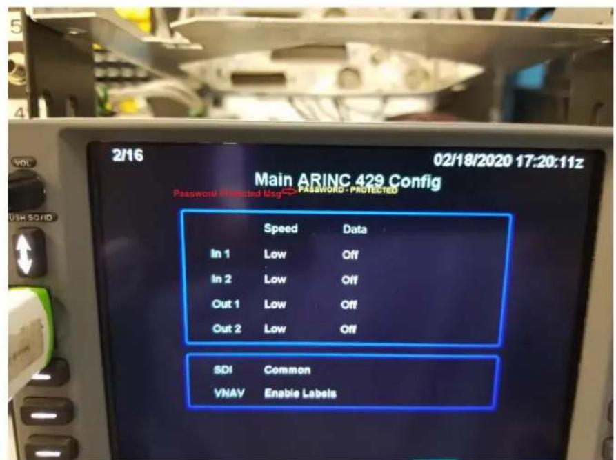
7.5.3 ARINC 429 Port Configuration

The ARINC 429 can be selected individually for each ARINC 429 Transmit and Receive Port. Each Transmit and Receive Port will have a "Speed" selection and "Data" selection.

Figure 12 IFD4XX ARINC 429 Configuration Page
Note: Shown is the IFD4XX ARINC 429 Config Page. The IFD5XX and Atlas Config Page has an OUT 1 and OUT 2.
IFD5XX and Atlas have OUT 2 with 5 settings - Off, ARINC 743A, ARINC 743A+, Onboard Radar, and Becker BXT Ctl
The "Speed" Selection will have the following options:
| Selection | Description |
| Low | Standard low-speed ARINC 429 (nominally 12.5 Kb per second) |
| High | High-speed ARINC 429 (nominally 100Kb per second) |
Table 95 ARINC 429 Speed Selection
The "Data" will have the following INPUT options:
| Selection | Description |
| Off | No device connected to this ARINC 429 input |
| Airdata | Altitude, temperature, and speed information from the following Air Data Systems: B&D 2600, 2601, 2800, 90004-003, Bendix/King KAD 280/480, Shadin ADC 2000 |
| Airdata/AHRS | Heading, altitude, temperature, and speed information from an Air Data/AHRS system. |
| EFIS | Selected course, heading, and joystick waypoint information from a EFIS system. Certain versions of the Collins and Honeywell EFIS may be compatible with this format. |
| EFIS/Airdata | Selected course, heading, joystick waypoint, altitude, temperature, and speed information. |
| Flight Control | Selected course information from the following Flight Control systems: Bendix/King KFC400 |
| Garmin GAD 42 | Selected course, heading, and true airspeed data from Garmin GAD 42. |
| Garmin GDL 88 Traffic | Garmin GDL 88 Traffic from the GDL 88/GTX 345 This ARINC 429 speed should be set to the high speed. |
| Garmin GDL 88 Traffic W/TCAS | Garmin GDL 88 with a Garmin GTS 800/820/825 or a L-3 SKY497/SKY 899 System Unsupported, reserved for future use This ARINC 429 speed should be set to the high speed. |
| Garmin GDL 88 Traffic W/TCAD | Garmin GDL 88 with a Avidyne TAS6XX or Ryan 9900BX System This ARINC 429 speed should be set to the high speed. |
| Garmin GDU | Selected course, heading, altitude, temperature and speed information from the following systems: Garmin GDU (G500/G600/GI-275) |
| Garmin GTX 330 | Garmin GTX330 (No TIS) This ARINC 429 speed should be set to the high speed. |
| Garmin GTX 330 w/Traffic | Garmin GTX 330 w/TIS This ARINC 429 speed should be set to the high speed. |
| Honeywell EFIS | Selected course, heading, and joystick waypoint information from the following EFIS systems:Aspen EFD1000 (If connected to an ACU1, set the ARINC 429 speed to low speed. If connected to an ACU2 and using ADF, RADALT or Remote OAT data set the ARINC 429 speed to high speed, otherwise low speed.)Honeywell Primus 1000Avidyne EXP5000* |
| INS/IRU | Heading information from the following Inertial systems:Bendix/King KAH 460Collins AHC 85Honeywell LaserefLitef LTR 81Litton LTN 90-100, LTN 91, LTN 92 |
| RADAR Graphics | Joystick waypoint information from a RADAR graphics unit |
| Radar Altimeter | Rockwell Collins ALT 1000/4000Garmin GRA 55/5500FreeFlight 4000/4500Honeywell RT 300BK KRA-10A |
| Sandel EHSI | Selected course and heading information from the following EHSI systems:Sandel SN 3308Sandel SN 3500Avidyne EXP5000* |
| Traffic Advisory | Traffic information from the following traffic advisory systems:Bendix/King KTA-870, KMH880Garmin GTS 800/820/850Garmin GDL 88Avidyne TAS6XX (but RS-232 is preferred)Ryan 9900BX (but RS-232 is preferred)L3 Communications SKY497 SkyWatchL3 Communications SKY899 SkyWatch HP |
| MLB 100 Traffic | Avidyne SkyTrax100/SkyTrax200/MLB100 or Freeflight FDL-978-RX Traffic (But RS232 is preferred) |
| Becker BXT | Becker BXT 65XX Transponder DisplayThis ARINC 429 speed should be set to the low speed. |
| Thales EFIS | Used when connected to a Thales FlytX system |
Table 96 ARINC 429 Input Selection
* Honeywell EFIS selection is preferred as it has more label information
Note: Only ARINC 429 Traffic is shared between IFDs on the CrossSync line, all other ARINC 429 devices may be wired to both IFDs in dual IFD installations since ARINC 429 data is generally not shared between IFDs via the CrossSync line.
The "Data" will have the following OUTPUT options:
| Selection | Description |
| Off | No device(s) connected to ARINC 429 output |
| ARINC 429 | Standard ARINC 429 output (non-GAMA) |
| GAMA 429 | ARINC data as define by the General Aviation Manufacturers' Association (GAMA) General Aviation Subset, 2^nd Edition. The output data includes navigation, flight plan information to the following systems:Garmin GAD 42 Interface AdapterCollins EFIS 84 (select “Non-WAAS” on the IFD)Bendix/King EFS 40/50 with update SW15/01 (GPS vertical guidance provided on EFIS)Certain other versions of Collins EFIS may also be compatible with this format. |
| GAMA 429Bendix King | ARINC 429 data as defined by the GAMA General Aviation Subset, 2^nd Edition. The output data includes navigation, flight plan and GPS vertical guidance information to the following systems:Bendix/King EFS 40/50 without SW15/01 update (GPS vertical guidance provided on EFIS) |
| GAMA 429Graphics | ARINC 429 data as defined by the GAMA General Aviation Subset, 2^nd Edition including GAMA Graphics Protocol ‘A’. This format outputs intersection symbols as generic waypoint symbols. The output data includes navigation and flight plan information (including graphical representation of the flight plan procedures) to the following systems:Honeywell Primus 1000 |
| GAMA 429Graphics w/Int | ARINC 429 data as defined by the GAMA General Aviation Subset, 2^nd Edition including GAMA Graphics Protocol ‘A’. The output data includes navigation and flight plan information (including graphical representations of flight plan procedures) to thefollowing systems: Sandel SN3308 Sandel SN3500 Aspen EFD1000 (see note below) Avidyne EX500 Avidyne EX600 Avidyne EX5000 Note: When integrating an Aspen EFD1000 with a dual IFD installation, ensure the “CRS SDI” field in the Aspen setup pages (page 18) is set to Nav 1/2 and not Common. |
| GAMA 429 Pro Line 21 | ARINC 429 data as defined by the GAMA General Aviation Subset, 2nd Edition. |
| GAMA 429 Sextant | ARINC 429 data as defined by the GAMA General Aviation Subset, 2nd Edition |
| GAMA 429 Non-standard | ARINC 429 data that is not necessarily conforming to the GAMA General Aviation Subset, 2^nd Edition. |
| GAMA 429 Thales | GAMA 429 Customized for Thales |
| ARINC 743A | ARINC 473A-5 Navigation Block Data |
| ARINC 743A+ | ARINC 473A-5 Navigation Block + Measurement Block |
| Onboard Radar | Honeywell RDR2000 |
| Becker BXT Ctl | Becker BXT 65XX Transponder Control This ARINC 429 speed should be set to the high speed. |
Table 97 ARINC 429 Output Selection
SDI
Note: It is important in dual IFD installations that the corresponding SDI selection be made properly. That typically means selecting LNAV 1 or LNAV 2.
| Selection | Description |
| Common | Rx: Accepts all 429 inputsTx: Generates all 429 outputs with SDI = 0 |
| LNAV 1 | Number 1 (Pilot) long-range navigatorRX: Accepts 429 inputs with SDI = 0 or 1.TX: Generates all 429 outputs with SDI = 1. |
| LNAV 2 | Number 2 (Copilot) long-range navigatorRX: Accepts 429 inputs with SDI = 0 or 2.TX: Generates all 429 outputs with SDI = 2. |
Table 98 SDI Selection
VNAV
| Selection | Description |
| Disable Labels | ARINC 429 labels associated with GPS-based vertical guidance (labels 117G and 327G) are not transmitted in the output data stream.Note: If replacing an existing GNS-530 and the VNAV field was not present on the 530, then select “Disable” on the IFD. |
| Enable Labels | ARINC 429 labels associated with GPS-based vertical guidance (labels 117G and 327G) are transmitted in the output data stream.ARINC 429 vertical:Sandel SN3500Aspen EFD1000Other systems may also use these labels. |
Table 99 VNAV Selection
7.5.4 RS-232 Port Configuration

The RS-232 Configuration Page allows the configuration Inputs and Outputs to match that of the equipment installed in the aircraft.

Figure 13 RS-232 IFD5XX Configuration Page
Note: Shown is an IFD5XX/Atlas Main RS232 Config Page. The IFD4XX only has 4 inputs and outputs
Note: For s/w 10.2.0 and earlier, if you configure Skytrax WX, Capstone Wx, MLB Wx, or WX500 on any input channel, the same numbered output channel cannot be configured with any of the following; ADS-B (Avi), ADSB, ADS-B+ (G), GDL 88, Aviation, Avtn no alt, HW EGWS, MapMX.
Note: RS232 Input 3 and Output 3 should only be used for CrossSync functionality. In single IFD installations configure RS232 Input 3 and Output 3 to Off.
The following selections can be made on the RS-232 Input.
Channel Inputs
| Selection | Description |
| Off | No device(s) connected to input of this channel |
| Arnav/ei-fuel | Serial fuel flow information from the following units: ARNAV FC-10, FT-10 Electronics International FP-5L |
| AXP322 | Select for Avidyne AXP322 Remote Transponder |
| CrossSync | Allows synchronization of flights plans, user waypoints, alerts and cross-side data (e.g. RS-232 Datalink, traffic, lightning, etc) between IFD units. Remote tuning of cross side radio is also (optionally) available. Transponder controls are not cross synced. Note: This is only an option for CHNL 3. |
| GDL 691 | Serial data input for in-flight access to weather and messaging from the following units: Garmin GDL69/69A P/N 011-00986-00 or 011-00987-00 only (Garmin software version 4.01 or later) pre Avidyne software 10.2.3.1. With software 10.2.3.1 and later P/N 011-03177-X0 will also work |
| XMD0761 | Serial weather data information from the Heads-up XMD-076 |
| XMD076 AUX1 | Read-only serial weather data information from the Heads-up XMD-076 to be used when a different device is controlling the Heads-up device. |
| Skytrax Wx1 | Serial weather data only information from the Avidyne Skytrax100/SkyTrax200/MLB100 or Freeflight FDL-978-RX |
| SkyTrax Trfc2 | Serial traffic data only information from the Avidyne Skytrax100/MLB100 or Freeflight FDL-978-RX |
| SkyTrax Trfc+Wx1,2 | Serial traffic and weather data information from the Avidyne Skytrax100/MLB100 or Freeflight FDL-978-RX |
| Capstone Wx1 | Garmin GTX 345 and other 3rd party compatible ADS-B weather devices transmitting at 38400 baud. |
| Capstone Trfc2 | Garmin GTX 335/345 and other 3rd party compatible ADS-B traffic devices transmitting at 38400 baud. |
| Capstone Trfc+Wx1,2 | Garmin GTX 345 and other 3rd party compatible ADS-B traffic and weather devices transmitting at 38400 baud. |
| Capstone HS Wx1 | Serial weather data information from any High Speed Capstone compliant ADS-B device transmitting at 115200 baud. |
| Capstone HS Trfc2 | Serial traffic data information from any High Speed Capstone compliant ADS-B traffic device at 115200 baud. |
| Capstone HS Trfc+Wx1,2 | Serial traffic and weather data information from any High Speed Capstone compliant ADS-B traffic device at 115200 baud. |
| MLB100 Wx1 | Serial weather data only for existing MLB100 installs. |
| Freeflight1,2 | Serial Freeflight transponder control protocol along with High Speed Capstone ADS-B traffic and weather data information from a Freeflight Ranger device. |
| NGT9000R | Serial transponder control protocol to control an L3 NGT9000R remote mount transponder. |
| Icarus-alt | Serial altitude data from the following units:Icarus Instruments 3000Sandia SAE5-35Garmin GTX 327 TransponderTrans-Cal Industries IA-RS-232-X, SSD120ACK Technologies A-30 (Mod 8 and above) |
| Ryan TCAD ^2 | Traffic information from a Ryan 9900B, 9900BX, or TAS6XX Series System. |
| Shadin-adc | Serial airdata information from the following units:Shadin ADC 200, 200+, 2000 |
| Shadin-alt | Serial altitude data from the following units:Shadin 8800T, 9000T, 9200T |
| Shadin-fadc | Shadin 9628XX-X Fuel/Air Data ComputerInsight TAS 1000 Air Data Computer |
| Shadin-Fuel | Serial fuel flow information from the following units:Shadin 91053XP and 91053XT-D “Digiflo-L” Digital Fuel Management SystemsShadin 91204XX(38)D and 91204XT-D “Miniflo-L” Digital Fuel Management SystemsJP Instrument EDM-700 or EDM-760 Engine MonitorOther JPI systems (e.g. JPI FS-450) can use this setting but see the specific format guidance from JPI for the Garmin GNS series. |
| WX-500 | Serial lightning data information from the L3 Communications WX-500 Stormscope |
| TWX | Serial lightning data information from the Avidyne TWX670 in “Native” format |
| Vhf Ctrl | Reserved for future VHF remote control |
Table 100 RS-232 Input Selection
^1 These weather receiving devices are mutually exclusive. Only one source can be displayed at one time. The current display priority is:
| GDL-69 |
| XMD076 |
| XMD076 Aux |
| Capstone HS Wx |
| Capstone HS Trfc+Wx |
| MLB100 Wx |
| Capstone Wx |
| Capstone Trfc+Wx |
| Freeflight |
^2 These Traffic receiving devices are mutually exclusive. Multiple devices should not be installed/configured on a single unit.
Channel Outputs
| Selection | Description |
| Off | No device(s) connected to output of this channel |
| ADS-B (Avi) ^3 | Serial position data to the following units:Trig TT31 (V 3.1 or later)Avidyne AXP340 |
| ADS-B+ (G) | Garmin GTX 330 Low Speed 9,600 Baud |
| ADS-B+ (G2) | Garmin GTX 335/GTX345/GDL 88 High Speed 38,400 Baud |
| Aviation ^3 | Serial position, altitude, velocity, and navigation data to the following units:Argus 3000, 5000, or 7000 Moving MapAvidyne FSD SeriesGarmin MX20 (V5.6 or later), GMX200Garmin GPSMAP 195, GPSMAP 295 or GPS III PilotGarmin GPSMAP 196, GPSMAP 296, and GPSMAP 396Garmin GPSMAP 496, and GPSMAP 696Garmin Aera 796/795Garmin GTX 327 TransponderJP Instruments EDM-700 or EDM-760 Engine MonitorShadin 91204XM Digital Fuel Management SystemShadin 91053XP Digital Fuel Management SystemShadin 9628XX-X Fuel/Air Data ComputerStormscope Series II (with NAVAID) Moving Map |
| Aviation no Alt ^3 | Serial position, velocity, and navigation data to the following units:Garmin MX20 (V5.5 or earlier)Horizon DDMPInsight TAS 1000 Air Data Computer |
| AXP322 | Select for Avidyne AXP322 Remote Transponder |
| CrossSync | Allows synchronization of flights plans, user waypoints, alerts and cross-side data (e.g. RS-232 Datalink, traffic, lightning, etc) between IFD units. Remote tuning of cross side radio is also (optionally) available. Transponder controls are not cross synced.Note: This is only an option for CHNL 3. |
| GDL 69 ^1 | Serial data output to a Garmin GDL69/69A P/N 011-00986-00 or 011-00987-00 only (Garmin software version 4.01 or later) |
| XMD076 ^1 | Serial weather control |
| SkyTrax Trfc ^2 | Serial traffic and weather control information to the Avidyne Skytrax100/MLB100 or Freeflight FDL-978-RX |
| SkyTrax Trfc+Wx ^1,2 | Serial traffic and weather control information to the Avidyne Skytrax100/MLB100 or Freeflight FDL-978-RX |
| Capstone Trfc ^2 | Garmin GTX 335/345 and other 3rd party compatible ADS-B traffic devices |
| Capstone Trfc+Wx ^1,2 | Garmin GTX 345 and other 3rd party compatible ADS-B traffic andweather devices. |
| Capstone HS Trfc2 | Serial traffic control information y High Speed Capstone compliant ADS-B traffic device at 115200 baud. |
| Capstone HSTrfc+Wx1,2 | Serial traffic and weather control information to High Speed Capstone compliant ADS-B traffic device at 115200 baud. |
| MLB100 Wx1 | Serial weather data only for existing MLB100 installs. |
| HW EGPWS3 | Serial communication to a Bendix/King KGP 560 EGPWS |
| Freeflight1,2 | Serial Freeflight transponder control protocol along with High Speed Capstone ADS-B traffic and weather data information from a Freeflight Ranger device. |
| NGT9000R | Serial transponder control protocol to control an L3 NGT9000R remote mount transponder. |
| MapMX3 | Serial position, altitude, velocity, and navigation data to the following units:Garmin MX20 (V5.7 or later), GMX 200 |
| Ryan TCAD2 | Traffic information and control to a Ryan 9900B, 9900BX, or TAS6XXA Series System. |
| WX-500 | Serial communication to L3 Communications WX500 Stormscope |
| TWX | Serial communication to the Avidyne TWX670 |
| Vhf Ctrl | Reserved for future VHF remote control |
| Raw-GPS | Reserved |
Table 101 RS-232 Output Selection
^1 These weather receiving devices are mutually exclusive. Only one source can be displayed at one time. The current display priority is:
GDL-69
XMD076
XMD076 Aux
Capstone HS Wx
Capstone HS Trfc+Wx
MLB100 Wx
Capstone Wx
Capstone Trfc+Wx
Freeflight
^2 These traffic receiving devices are mutually exclusive. Multiple devices should not be installed/configured on a single unit.
^3 The following RS232 Output protocols may be configured on two or more RS232 ports: Aviation, Aviation No Altitude, ADS-B (avi), HW EGPWS, and MapMx.
7.5.5 Main System Configuration

This is a general page for miscellaneous configurations.
Main System Config
| Fuel Type | AV Gas | Joystick Input | Disabled |
| GPS Select | Auto | Appr Roll Steer | Enabled |
| Airframe | Helicopter | Nav Radio Active | Enabled |
| Multi-Engine | Enabled | Charts | Enabled |
| Tail Number | N51166 | BEW | 15000 lb. |
| External TAWS | No | MTOW | 25000 lb. |
| WOW Input (Helo) | No | MLW | 20000 lb. |
| Checklists | Enabled | RF Legs | Enabled |
| TIS-B Annunciation | Enabled | Enroute VNAV | Enabled |
Figure 14 Main System Configuration Page
The Main System Configuration Page (Page 3 of 15) allows the configuration of the following Airframe Options and GPS Parameters on the IFD.
Fuel Type Selections:
| Selection | Description |
| Avgas | The aircraft is using Aviation gas (5.967 lbs/gal) |
| Jet A | The aircraft is using Jet A or Jet A-1 fuel (6.843 lbs/gal) |
| Jet B | The aircraft is using Jet B (JP-4) fuel (6.467 lbs/gal) |
Table 102 Aircraft Fuel Type
GPS Select Selections:
| Selection | Description |
| Auto | In GPS mode on the IFD, the GPS Select discrete will not be active (open) in a GPS approach, and no messages will annunciate on the IFD and no pilot action is required. This setting allows the pilot to use the GPS → VLOC Capture option on the User Options part of the Setup tab on the AUX page. |
| Prompt | In dual IFD installations, only the IFD connected to a KFC225 autopilot should be setup for prompt. In GPS mode, the user will be prompted to enable the approach in KFC225 equipped aircraft When Prompt is selected, and a GPS approach mode is active, a CAS message will prompt the pilot to “Enable A/P Approach” on the FPL tab. At that point, the pilot may then enter APR mode on the autopilot. This setting will also ignore the GPS → VLOC Capture option on the User Options part of the Setup tab on the AUX page. |
Table 103 GPS Sequencing
Airframe Selections: ^2
| Selection | Description |
| Fixed Wing | For Fixed Wing installations |
| Helicopter | For Helicopter installations |
| High Speed | For Jet installations |
| Canard | For Fixed Wing installations (ownership symbol has a canard) |
Table 104 Airframe Selection
Multi-Engine Selections:
| Selection | Description |
| Disabled | For non-twin engine installations. Fuel pages show single value for total fuel quantity and fuel flow |
| Enabled | For twin engine installations. Fuel pages show separate values for fuel quantity and fuel flow, one per engine |
Table 105 Multi-Engine Selection
Tail Number:
Tail number is a text field and is used for various purposes (i.e. Jeppesen data subscription, transponder function and optional IFD feature validation such as TAWS, 16 Watt VHF, GLAS, SAR, Radar etc.). Note if the tail number is not entered to match the paid option features installed at the factory or through the use of coupons or if the tail number should change for any reason doing subsequent software upgrades in the field will result in turning off those options. If the tail number of the aircraft is changed please contact Avidyne Technical Support at techsupport@avidyne.com and a file to restore the options can be emailed to you.
External TAWS Selections:
| Selection | Description |
| Yes | Select if an external EGPWS or TAWS device (e.g. KGP 560) is connected to the IFD or if you want to turn off the FLTA. It will disable FLTA and TA functionality as well as aural alerts in the IFD |
| No | Select when no external EGPWS or TAWS device is connected to the IFD, thereby enabling all enabled IFD terrain alerting functions. |
Table 106 External TAWS Selection
Remote data collection units can be configured to collect system information over the Wi
WOW Input (Helo)
| Selection | Description |
| Yes | When set to “Yes” and the Airframe Selection is set to “Helicopter” Pin 70 on P1001 is used as a discrete input to control the in-air or on-ground state of the IFD. Logic state required is “low when on ground” |
| No | Select “No” when WOW discrete input is unavailable. |
Table 107 Weight on Wheels
Checklist
| Selection | Description |
| Enabled | Select Enabled to allow the user editable checklists to be displayed/accessible. |
| Disabled | Default setting |
Table 108 Checklist Setting
TIS-B Annunciation
| Selection | Description |
| Enabled | Select Enabled for installations in U.S. |
| Disabled | Outside US airspace |
Table 109 TIS-B Annunciations
Joystick Input
| Selection | Description |
| Enabled | Enables joystick input commands. Controls the automatic creation of user waypoints using external EFIS input. This setting shall be disabled when interfacing to the Proline 21 installations. |
| Disabled | Default setting |
Table 110 Joystick Input
Appr Roll Steer
| Selection | Description |
| Enabled | Default setting |
| Disabled | Invalidates GPSS Roll Steering output during FMS approaches. Should be disabled for autopilots that fly GPSS during approach mode to force the autopilots to switch to Left/Right deviation data. |
Table 111 Roll Steering Setting
Nav Radio Active
| Selection | Description |
| Enabled | Default setting |
| Disabled | When there is no nav antenna connected to the IFD |
Table 112 Nav Radio Active Setting
Charts
| Selection | Description |
| Enabled | Default setting |
| Disabled | Electronic charts capability is inhibited. The Map subsystem will not show a Charts tab, the Map tab will not show chart extent boxes, the FMS will not show chart icons. This setting is useful if the charts subscription has expired and there is no intent to update it. If enabled in that situation, the IFD will display a cautionary message at power up saying that the charts have expired. |
Table 113 Charts Setting
BEW, MTOW, MLW
Aircraft Basic Empty Weight, Maximum Takeoff Weight, Maximum Landing Weight. All of these settings are numeric fields and are used to drive the Weight Calculator in the IFD. Rotating the inner knob changes the value by 10 pounds for each click. Values can range from 0 to 50000 pounds.
RF Legs
| Selection | Description |
| Enabled | Enables the FMS to allow the selection of instrument procedures containing Radius-To-Fix (RF) legs, display those legs on the map, and provide guidance for active RF legs.This option should only be enabled if the aircraft is properly equipped (see AFMS). |
| Disabled | Default setting |
Table 114 RF Legs Setting
Enroute VNAV
| Selection | Description |
| Enabled | Default setting. Enables the “VNAV” function in the FMS to provide linear vertical deviations in descent during enroute and terminal navigation modes. Requires a baro-corrected altitude input.This option should only be enabled if the aircraft is properly equipped (see AFMS).Msg 126 Vertical Deviation and Msg 322 Flight Path Angle aretransmitted on GPS ARINC Output see Table 65NOTE: VNAV integration to primary instruments or flight control systems requires separate approval if not specifically identified in this document |
| Disabled | Prevents the “VNAV” function in the FMS from providing vertical deviations during enroute and terminal navigation modes. |
Table 115 Enroute VNAV Setting
Note: It is imperative that only one source of terrain cautions and warnings be enabled on the airplane so as to avoid the potential for conflicting information to be presented to the pilot. If a TAWS system is installed but the IFD's internal Fixed Wing TAWS (paid option), or TA and FLTA functions are to be used for terrain avoidance, the TAWS system must be fully disabled. If a separate TAWS system is to be used the caution and warning indications generated by the TAWS system can be displayed on a remote third party annunciator and the IFD's TA and FLTA displays and audio must be inhibited.
Note: The IFD system supports Honeywell EGPWS systems with a remote third party annunciator only. All other external TAWS/EGPWS systems must be disabled if the internal Fixed Wing TAWS (paid option) or TA and FLTA are to be operational
7.5.6 Main Input Configuration

The Main Input Page displays information received from ARINC 429, RS-232, and other electrical inputs. This page is helpful during troubleshooting of the IFD system. This is used for verifying electrical interfaces during installation and troubleshooting.
| Field | Description |
| OAT | Outside Air Temperature |
| SAT | Static Air Temperature |
| TAT | Total Air Temperature |
| IAS | Indicated Airspeed |
| W SPD | Wind Speed |
| HDG | True Heading |
| W DIR | Wind Direction |
| GPS SC | GPS Selected Course |
| VLC SC | VOR/LOC Selected Course (Not on IFD510/545/410) |
| CDI | Status of the CDI Key (Not on IFD510/545/410) |
| B ALT | Baro Corrected Altitude |
| D ALT | Density Altitude |
| P ALT | Pressure Altitude |
| JOYSTICK WPT | Latitude and longitude of a joystick waypoint sent by an EFIS or Radar indicator |
Table 116 "Main Inputs" Page Fields
7.5.7 Main Lighting Configuration
The source of the lighting for the IFD can be the bezel photocell sensor or the dimming bus. 28VDC, 14VDC, 5VDC and 5VAC dimming buses are all supported and are automatically detected by the IFD.

Figure 15 Main Lighting Configuration Page
Photo Response Time
Sets the speed at which the brightness changes when photocell is selected as the lighting source. Both the Bezel and Display fields have a range of 1 to 5, and the factory default is 3.
Photo Slope
The Photo Slope sets the sensitivity of the display/bezel to changes in the input when the dimming source is the IFD photocell. This field has a range of 15 to 100, and the factory default is 80.
Photo Minimum
The Photo Minimum sets the minimum brightness when the dimming source is the photocell. Both the Bezel and Display fields have a range of 1 to 50, and the factory default is 1.
Photo Maximum
The Photo Maximum sets the maximum brightness when the dimming source is the photocell. Both the Bezel and Display fields have a range of 50 to 100, and the factory default is 100.
dimBus Transition %
The dimBus Transition % sets the threshold where the aircraft dimming bus takes over from the photocell. Below this threshold, the aircraft dimmer controls the IFD lighting. Both the Bezel and Display fields have a range of 0 to 100, and the factory default is 10.
Note: If it is not desired to hand brightness control over to the dimming bus from the photocell at any point, set dimBus Transition % to 0 (zero). Doing so will prevent the scenario where, in increasingly darker environments (e.g. flying past sunset into dark night), the display automatically dims and dims and dims and then suddenly jumps to bright.
dimBus Slope
The dimBus Slope sets the sensitivity of the display/bezel to the aircraft dimmer. Both the Bezel and Display fields have a range of 15 to 100, and the factory default is 60.
Note: Previous to Release 10.1.1.0, a dimBus slope value of 100 on the AviCurve resulted in a maximum brightness value of 21%. In Release 10.1.1.0 and later, a slope value of 100 will result in 100% maximum brightness.
dimBus Minimum
The dimBus Minimum sets the minimum brightness when the aircraft dimmer is the dimming source. Both the Bezel and Display fields have a range of 1 to 50, and the factory default is 1.
dimBus Maximum
The dimBus Maximum sets the maximum brightness when the aircraft dimmer is the dimming source. Both the Bezel and Display fields have a range of 50 to 100, and the factory default is 100.
dimBus Curve
The dimBus Curve sets the aircraft dimming bus to either a Proportional Curve or AviCurve on the IFD.
The Proportional Curve tracks the aircraft lighting bus as follows: Maximum night lighting at maximum aircraft lighting bus voltage, Minimum night lighting at minimum aircraft lighting bus voltage (linear in-between).
The AviCurve tracks the aircraft dimming bus as follows:

Figure 16 Lighting Curve – AviCurve
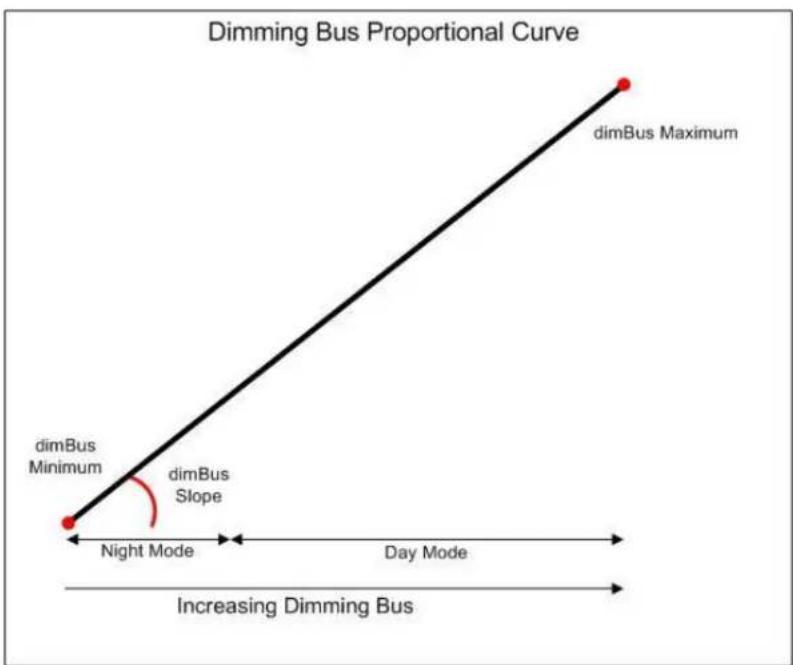
Figure 17 Lighting Curve - Proportional Curve
| Field | Selection |
| Bezel | Value displayed represents the current % brightness of the bezel backlighting |
| Display | Value displayed represents the current % brightness of the display backlighting |
| Mx Input | Photocell - Maintenance Mode will use this method if selected. This is the default setting. This setting uses the Photocell on the IFD bezel or display.dimBus - Maintenance Mode will use this method if selected. This setting uses the aircraft lighting buss to control the lightning of the bezel or display. |
Table 117 Lighting Bus Configuration
Dimming Bus Calibration
The section will calibrate the IFD to the aircraft avionics lighting bus.
| Selection | Description |
| dimBus Type | DC - select this option if the dimming bus is a DC bus. AC - select this option if the dimming bus is an AC bus. The IFD needs to know the bus type in order to alter internal configuration as well as properly perform the calibration. |
| dimBus Max Voltage | Sets the maximum aircraft dimming bus voltage. Range is 0 - 28V. |
| dimBus Min Voltage | Sets the minimum aircraft dimming bus voltage. Range is 0 - 28V. |
Table 118 Dimming Bus Calibration
To calibrate the dimming bus:
- Select desired dimBus Type;
- Select the dimBus Max Voltage field;
- Push the right bezel knob;
- Set the dimming bus to the maximum value (e.g. full clockwise position on dimming rheostat);
- Push the right bezel knob to store;
Repeat the process for the minimum value (use full counter-clockwise position of rheostat)
7.5.8 Main Discrete I/O

This page will test the Main Discrete outputs on the IFD.

Figure 18 Main Discrete I/O Configuration Page
| Selection | Verify That |
| RMT CDI | On is displayed when a remote CDI source select switch is pressed. |
| RMT OBS | On is displayed when a remote OBS switch is pressed. |
| TER INHB | On is displayed when a remote TERRAIN INHIBIT switch is pressed. |
| RMT RCL | On is displayed when the COM REMOTE RECALL switch is pressed. |
| AUD INHB | On is displayed when the audio inhibit discrete input is asserted. |
Table 119 External Switch State
| Selection | Verify That |
| APR | The APR annunciator is on or off as selected on this page. |
| GPS | The GPS source select annunciator is on or off as selected on this page. |
| INTEG | The INTEG annunciator is on or off as selected on this page. |
| MSG | The MSG annunciator is on or off as selected on this page. |
| OBS | The OBS annunciator is on or off as selected on this page. |
| TERM | The TERM annunciator is on or off as selected on this page. |
| VLOC | The VLOC source select annunciator is on or off as selected on this page. |
| WPT | The WPT annunciator is on or off as selected on this page. |
| ILS/GPS APR | The ILS/GPS APR output is on or off as selected on this page (NOTE: This output is connected to the autopilot ILS ENGAGE input, not to an annunciation, and therefore this is for bench testing purposes only). |
| GPS SELECT | The GPS SELECT output is on or off as selected on this page (NOTE: This output is connected to the autopilot GPS SELECT input, not to an annunciation, and therefore this is for bench testing purposes only). |
| TER CAUT | The TER CAUT annunciator is on or off as selected on this page. |
| TER INHB | The TER INHB annunciator is on or off as selected on this page. |
| TER N/A | The TER N/A annunciator is on or off as selected on this page. |
| TER WARN | The TER WARN annunciator is on or off as selected on this page. |
| RP MODE | The Reduced Protection annunciator is on or off as selected on this page. Applicable only when HTAWS is enabled (TAWS and HELO options both enabled). |
Table 120 Discrete Toggles
7.5.9 Main CDI/OBS Config Page
This page will test the Main CDI/OBS output on the IFD.

Figure 19 Main CDI/OBS Configuration Page
The following parameters can be tested:
CDI (LAT/VERT)
| Selection | Description |
| Max Left | The remote CDI will be off-scale full deflection to the left/up |
| Full Left | The remote CDI will be deflected to the left/up |
| Center | The remote CDI will be centered |
| Full Right | The remote CDI will be deflected to the right/down |
| Max Right | The remote CDI will be off-scale full deflection to the right/down |
Table 121 Main CDI Test Page
| Selection | Description |
| Hidden | The lateral and vertical flag on the external indicator is hidden |
| In view | The lateral and vertical flag on the external indicator is in view |
*This function will only test the low level flags, and does not support the testing of Super Flags
Table 122 Main CDI Flag Test Page
TO-FROM
| Selection | Description |
| FROM | The FROM flag on the external indicator is in view |
| Hidden | The TO/FROM flag on the external indicator is hidden |
| TO | The TO flag on the external indicator is in view |
Table 123 Main CDI Flag Test Page
Selected Course
This section will calibrate the external CDI/HSI to the IFD.
- Select 150° on the CDI/HSI;*
- Verify the Selected Course is displayed on the IFD and press the ENTR button on the IFD.
- After calibrating, verify 30^ increments on the CDI/HSI are properly displayed on the IFD ±2^ .
* In order to do the OBS calibration on a KI208A or KI209A, you have to toggle to the "Main Discrete I/O" page, and turn "ON" the GPS discrete toggle. Then turn to the Main CDI/OBS config page (without toggling back to the Discrete I/O page) and calibrate the OBS by dialing 150 degrees on the indicator.
Ignore Options
| Selection | Description |
| Ignore SEL CRS for GPS | Yes/No - Nav Source knob used in OBS. Yes = ignore analog or 429 selected course. OBS mode then uses the Nav Source knob to dial the course. |
| Ignore SEL CRS for VLOC (N/A for 1FD510/545/410 | Yes/No - Yes = Lateral navigation flag displays VOR validity, deviation data for VOR is always centered. No = deviation and flag data is based on OBS selection. |
Table 124 Ignore Options Selection
CDI Selection
| Selection | Description |
| GPS | The GPS is the navigation source. The GPS annunciator will also be active. This is the setting for IFD510/545/410 |
| VLOC(N/A for IFD510/545/410) | The VLOC is the navigation source. The VLOC annunciator will also be active. |
| GPS Only(N/A for IFD510/545/410) | The VLOC selection on the IFD Nav Source knob has been disabled. Therefore, GPS and OBS are the only two available choices via the IFD Nav Source knob |
Table 125 CDI Source Selection
OBI Source
| Selection | Description |
| Always GPS | The MAIN Serial OBI output will always be selected to GPS. |
| Track CDI | The MAIN Serial OBI will track the Nav Source knob selection. |
Table 126 OBI Source Selection
V-Flag State
| Selection | Description |
| Declutter | The vertical deviation bar will be in parked in the maximum UP position when the vertical flag is removed, except in the following cases:VLOC is selected on the Nav Source knob and an ILS frequency is tuned (N/A for lFD510/545/410)GPS is selected on the Nav Source knob and valid GPS approach is active (precision GPS with vertical guidance) |
| Normal | The vertical deviation bar will be in the center position when vertical navigation is invalid and the vertical flag will be present. |
Table 127 V-Flag State
7.5.10 VOR/LOC/GS CDI
Note: This page is not applicable for the IFD510/545/410 or Atlas FMS Only units.
This will test the operation of the VOR/LOC/GS output from the IFD on the P1006 connector to an external CDI/HSI display.

Figure 20 CDI Test Page
Note: This page currently will only test low level flags and does not support the testing of super flags
CDI (LAT/VERT)
| Selection | Description |
| Max Left | The external CDI will be off-scale full deflection to the left/up |
| Full Left | The external CDI will be deflected to the left/up |
| Center | The external CDI will be centered |
| Full Right | The external CDI will be deflected to the right/down |
| Max Right | The external CDI will be off-scale full deflection to the right/down |
Table 128 Navigation CDI Test Page
NAV Flag (LAT/VERT)
| Selection | Description |
| Hidden | The lateral and vertical flag on the external indicator is hidden |
| In view | The lateral and vertical flag on the external indicator is in view |
Table 129 Navigation Flag Test Page
SPR Flag (LAT/VRT Super Flag)
| Selection | Description |
| Hidden | The lateral and vertical flag on the external indicator is hidden |
| In view | The lateral and vertical flag on the external indicator is in view |
Table 130 NAV Superflag Test Page
TO-FROM
| Selection | Description |
| FROM | The FROM flag on the external indicator is in view |
| Hidden | The TO/FROM flag on the external indicator is hidden |
| TO | The TO flag on the external indicator is in view |
Table 131 Navigation TO/FROM Page
Selected Course
This section will calibrate the external CDI/HSI to the IFD.
-
Select 150° on the CDI/HSI;*
-
Verify the Selected Course is displayed on the IFD and press the ENTR button on the IFD;
-
After calibrating, verify 30^ increments on the CDI/HSI are properly displayed on the IFD ± 2^ .
* In order to do the OBS calibration on a KI208A or KI209A, you have to toggle to the "Main Discrete I/O" page and turn on the GPS discrete toggle. Then turn to the Main CDI/OBS config page (without toggling back to the Discrete I/O page) and calibrate the OBS by dialing 150 degrees on the indicator
DME Channel Mode
This configuration allows you to set the format for the DME tuning data output.
| Selection | Description |
| UNINSTALLED | No DME installed/configured |
| King Serial | King Serial DME tuning |
| Parallel 2x5 | 2 of 5 parallel DME tuning |
| Parallel BCD | Shifted BCD (Binary Coded Decimal) parallel DME tuning |
| Parallel Slip | Slip-code parallel DME tuning |
| Narco 890/891 | 2 of 5 parallel DME tuning, compatible with the following DME units:Narco DME 890Narco DME 891ARC (Cessna) RTA-476A |
Table 132 DME Channel Mode
7.5.11 VOR/LOC/GS ARINC 429 Configuration

Note: This page is not applicable for the IFD510/545/410 or Atlas FMS Only units.
This page will configure the ARINC 429 for the VOR/LOC/GS output.
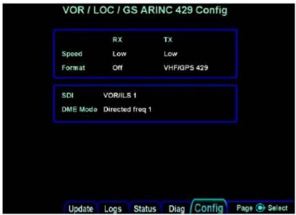
Figure 21 VOR/LOC ARINC 429 Configuration Page
The following parameters can be configured.
Speed:
| Selection | Description |
| Low | Standard Low-speed ARINC 429 |
| High | High-speed ARINC 429 |
Table 133 VOR/LOC/GS ARINC 429 Speed Configuration
Format:
| Selection | RX/TX | Description |
| OFF | RX | No data will be processed from an external device |
| Proline VHF | RX | Processes VOR, LOC, G/S, and frequency information from a remote Pro Line 21 radio. Required to be paired with the Proline VHF/GPS TX option |
| VHF 429 | TX | Standard VOR, Localizer, Glideslope, and Frequency information |
| VHF/GPS 429 | TX | Standard VOR, Localizer, Glideslope, Frequency information as well as Pseudo Localizer and Pseudo Glideslope during GPS approach with CDI set to GPS. |
| Proline VHF/GPS | TX | Pass-through of Pro Line 21 radio data as well as pseudo LOC and G/S during GPS approach with CDI set to GPS. |
| VHF Thales | TX | Standard VOR, Localizer, Glideslope, Frequency information as well as Transponder and Diagnostic data |
Table 134 VOR/LOC/GS ARINC429 Format Selection
SDI:
| Selection | Description |
| Common | RX: Accepts all 429 inputsTX: Generates all 429 outputs with SDI =0 |
| VOR/ILS 1 | Number 1 (Pilot) VOR/ILS ReceiverRX: Accepts 429 inputs with SDI = 0 or 1TX: Generates all 429 outputs with SDI = 1 |
| VOR/ILS 2 | Number 2 (Copilot) VOR/ILS ReceiverRX: Accepts 429 inputs with SDI = 0 or 2TX: Generates all 429 outputs with SDI = 2 |
Table 135 VOR/LOC/GS SDI Selection
DME Mode:
| Selection | Description |
| Directed Freq 1 | If the IFD is connected to a single-channel or multi-channel ARINC429 DME, Direct Freq 1 will channel Receiver 1. |
| Directed Freq 2 | If the IFD is connected to a multi-channel ARINC429 DME, Direct Freq 2 will channel Receiver 2 |
Table 136 DME Mode Selection
7.5.12 Com Setup
Note: This page is not applicable for the IFD510/545/410 or Atlas FMS Only units.
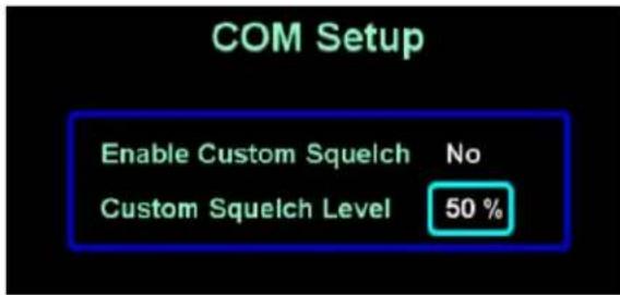
Enable Custom Squelch
| Selection | Description |
| No | Default squelch values will be used |
| Yes | The custom squelch value entered will be used for COM squelch |
Table 137 Enable Custom Squelch Setting
Custom Squelch Level
Custom squelch level is a numeric field ranging from 50% to 80%. Rotate the inner knob to adjust the numeric value by 1% with each click.
7.5.13 GPS Setup
This page will configure the GPS Receiver for the antenna offset on the aircraft and designate if the IFD will use the WAAS functionality of the system.

Figure 22 GPS Antenna Setup
Measure the distance from the ground to the top of the GPS antenna to nearest tenth of a foot, as shown in the image below, and enter the value into the IFD (to the nearest 1/10^th foot).

Figure 23 GPS Height
Antenna Type
| Selection | Description |
| WAAS | The GPS antenna connected to the IFD is approved for use in SBAS operations. |
| Non-WAAS | The GPS antenna connected to the IFD is not approved for use in SBAS operations |
Table 138 Antenna Type Setting
Excluded SV 1, 2, 3, 4
These fields are used to prevent the GPS from using the specified satellites, by SV number. Rotate the inner knob to change the satellite number. Set all fields to zero to prevent the GPS from excluding any satellites.
7.5.14 Main ARINC 429 Port 3 Configuration
This page will configure a GLAS enabled IFD to transmit a pseudo VOR/ILS output to the flight displays and autopilot on ARINC 429 port 3. Only configure this setting if high speed VOR/ILS ARINC out is specified on the drawing.

Figure 24 ARINC 429 Port 3 Setup
Set the ARINC 429 speed to high and select Proline VHF/GPS in the Out 3 section.
7.5.15 GPS Legacy Avionics System (GLAS)
Description:
GLAS (GPS Legacy Avionics System) is a paid for software unlock that enables legacy avionics that are "pre-WAAS" to fly GPS approaches with vertical guidance via the existing EFIS A429 short range navigation (SRN)/VLOC input channel utilizing Avidyne proprietary software.
During GPS Approach operations, the IFD or Atlas communicates the selected GPS approach guidance on a dedicated ARINC 429 VLOC output channel. The result is displayed and coupled flight guidance information for GPS approaches utilizing the EFIS FGS SRN input channel(s).
With the GLAS option configured, the A429 VLOC TX/RX ports on P1006 are high speed / low speed configurable. The IFD P1050 connector also supports a dedicated GLAS A429 out channel where dual channeling is required.
The A429 GLAS settings in the IFD/Atlas will not work if GLAS enablement is not unlocked.
Approach Capabilities:
With the appropriately rated TSO-C190 GPS antenna installed and the IFD/Atlas configured correctly, GPS approach capabilities include the following:
LNAV: Lateral Guidance only. Standard GPS precision 0.3NM deflection
LNAV+V: Lateral Navigation w/ Advisory Vertical Guidance
LNAV/VNAV: Lateral and Vertical Navigation
LP: Localizer Performance (no vertical guidance)
LP+V: Localizer Performance w/ Advisory Vertical Guidance
LPV: Localizer Precision with Vertical Guidance.
Configuration:
There are two GLAS configuration options: Of these two, Proline VHF/GPS is only used when the IFD/Atlas on-board radio is not installed (IFD510/545).
VHF/GPS 429
When using the VHF/GPS 429 configuration, the IFD uses its internal VHF navigation sensor data up until a GPS approach is active. At this point "pseudo-ILS" data based on GPS deviations replaces the VLOC data.
Proline VHF/GPS
In situations where the IFD onboard VHF navigation is not installed (FMS+VCom or FMS only), or when the VHF navigation is not being utilized and turned off from the maintenance mode, the IFD can be inserted in the middle of the communication chain between the aircraft's existing VHF navigation sensor and the EFIS/FGS systems for the purpose of overriding the existing VHF nav data.
For this application the existing A429 VLOC data is interrupted. The information from the existing SRN sensor is then passed through the IFD for management.
7.5.16 GDL Configuration Pages
This page allows the configuration of the Garmin GDL 69/69A. This page is always displayed in Maintenance Mode. The GDL 69/69A must be activated prior to configuring the IFD, reference the GDL installation manual for setup and configuration information.

Figure 25 GDL Configuration Page
GDL Selection Page
This page selects the attenuation and the type of GDL receiver connected to the IFD.
| Selection | Description |
| Attenuation | This parameter sets the attenuation GDL 69/69A. Reference the Garmin GDL69/69A installation manual for more information. |
| Model | This parameter sets the model to either GDL 69 (weather only) or GDL 69A (weather and audio) models. |
Table 139 GDL Selection Page
Note Compatibility with P/N 011-00986-00 or 011-00987-00 only pre software 10.2.3.1. With software 10.2.3.1 or higher P/N 011-03177-X0 will also function
Note: If the GDL69/69A is connected to any other display in the aircraft, this attenuation setting must be set to match them.
7.5.17 Remote XPDR Configuration
This page will configure the Avidyne AXP322 Remote transponder. Reference the AXP322 installation manual as needed. The transponder must be configured to operate.
Please note; it may take up to 3 minutes to update the transponder configuration after changing a parameter below.
A dual AXP322 transponder installation will require that this function is performed on both transponders
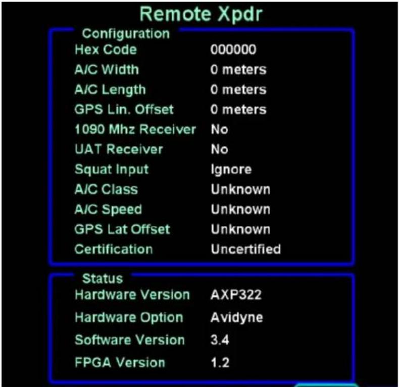
| Selection | Description |
| Hex Code | Enter the aircraft's Mode S Address issued by the registration authority. This code must be entered as a hexadecimal value. |
| A/C Width | Enter the aircraft's width in meters |
| A/C Length | Enter the aircraft's length in meters |
| GPS Lin. Offset | Enter the distance from the front of the aircraft to the GPS antenna in meters |
| 1090 MHz Receiver | Enter "Yes" if the aircraft is equipped with 1090 MHz ADS-B In receiver |
| UAT Receiver | Enter "Yes" if the aircraft is equipped with UAT ADS-B In receiver |
| Squat Input | For ADS-B out compliance, a squat switch is required forautomatically transitioning the transponder to air/alt/ground modes of operation.For aircraft without a squat switch, connect the squat switch input of the transponder to P1001 pin 8 of one of the IFD5XX/IFD4XX and set the transponder to “Avidyne”.If using an external squat switch, set this field to “Active Low+” or “Active High+” based on the polarity requirements of the external squat switch. |
| A/C Class | Enter the aircraft category |
| A/C Speed | Enter the aircraft speed |
| GPS Lat. Offset | Enter the lateral distance in meters for the GPS antenna |
| Certification | VFR installations, aircraft with a non-WAAS antenna (reference Section 7.5.12), or unapproved ADS-B out installations must set this field to "uncertified". All other installations reference the Avidyne AXP322 installation manual for certification level. |
Table 140 Remote XPDR Configuration Selections
7.5.18 Voice Call Outs Configuration
The IFD has the capability to generate an aural alert (a.k.a. "voice call out") at certain AGL altitudes when approaching an airport. This page allows enabling or disabling of alerts at each of those altitudes. When the Fixed Wing TAWS option is enabled, the 500ft callout cannot be disabled. The IFD will only generate these aural alerts when either the F500 or TAWS option is enabled.
NOTE: If the IFD is configured for use with an external TAWS, this setting will not be shown and the altitude callouts will be inhibited as if the setting was "Off".

7.5.19 Wireless Portables
This page is used to configure the operation of the IFD with respect to wireless portable devices.

Capstone
| Selection | Description |
| Enabled | If the IFD has the PORTS option enabled and the IFD is not hardwired to an ADS-B In device*, and any CrossSync connected IFD is not hardwired to an ADS-B In device*, then the IFD can be configured to receive ADS-B data from a wireless portable device such as a Stratus 3.If all of the above conditions are true, then setting the Capstone configuration on this page to Enabled will enable the configuration to allow the IFD to receive ADS-B In data from the wireless device. Note that receipt of ADS-B data from the portable device must also be enabled via the flight mode setup pages. Finally, like all Wi-Fi connected devices, the Pilot will be required to “allow” the portable device to connect to the IFD. See Pilot Guide for details.* No RS-232 ports and no ARINC-429 ports are configured for an ADS-B In device |
| Disabled | Default configuration |
Table 141 Wireless Portables Selections
7.5.20 WiFi Setup
All WiFi setup is accomplished via the Flight Mode setup pages. See Pilot Guide for details.
7.5.21 Bluetooth Setup
The IFD has built-in Bluetooth capability that allows pairing with a remote keyboard. The keyboard can be used to easily enter waypoint identifiers, but it can also be used to change pages, move cursor, and tune radios.
As with all Bluetooth devices, a keyboard must be paired with the IFD before use. This pairing only needs to be done once and then that specific keyboard can be used every time the IFD is powered up. This page is used to establish the pairing.
After power up, the IFD goes through a process to initialize the Bluetooth interface. During that time, this page will show "Initializing..." and the aircraft will move across the screen from left to right, as illustrated below.

Figure 26 Bluetooth Setup Page – Initializing
Press the button on the back of the keyboard to make it discoverable. Then, press the "Start Scan" LSK on the IFD.

Figure 27 Bluetooth Setup Page – Start Scan LSK
After a while, the IFD will discover the keyboard and it will appear on the list of devices shown on the screen. At that point, press the "Stop Scan" LSK.

Figure 28 Bluetooth Setup Page – Keyboard discovered
After "Stop Scan" has been pressed, turn the right outer knob to move the cursor to the desired device. Press the "Pair Device" LSK and wait for a numeric pairing code to appear.

Figure 29 Bluetooth Setup Page – Pair Device LSK
![18/19 05/10/2021 18:30:18z Bluetooth Setup Legend: Discovered Paired ✓ Connected Unknown Unknown Bluetooth Keyboard Type the following code on your Bluetooth keyboard 4305 [Enter] Update Logs Status Diag Config](/content/2026/05/956098/images/dcc0a9f13c3e5541f6d2b6339de2f8dc65469732993c2fa0f905b6ab88dc2172.jpg)
Figure 30 Bluetooth Setup Page – Pairing Code
On the keyboard, enter the numeric code followed by the keyboard's ENTR key. If pairing was successful, the selected device in the list will be shown in green.
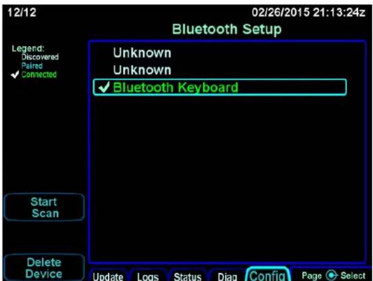
Figure 31 Bluetooth Setup Page – Pairing Successful
If the device is not shown in green or if the device name disappears from the display, restart the pairing process with pressing the button on the back of the keyboard. If repeated attempts to pair are unsuccessful, contact Avidyne Technical Support.
7.5.22 IRU Calibration, IFD545, IFD550, Atlas
In order to calibrate the IFD550, IFD545 or Atlas you must access the IRU Calibration page. This page can be found by:
- Entering maintenance mode.
- Accessing the Config tab by pressing the right side of the AUX key.
- Turn the outer right knob until you see the IRU Calibration page (see picture below).
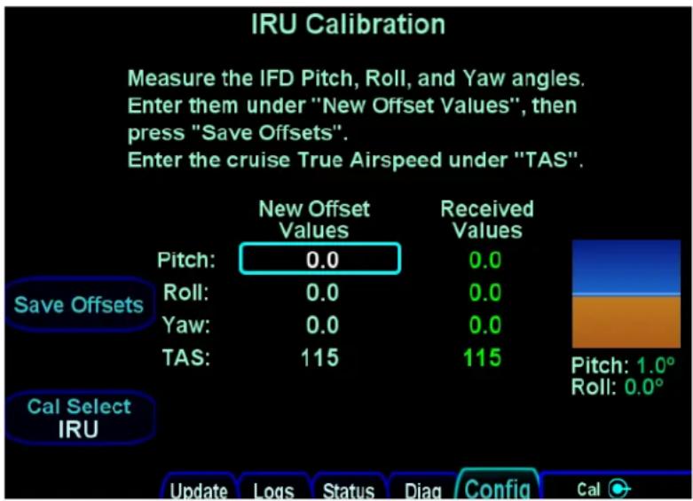
Figure 32 IRU Calibration Page
IFD550, IFD545, Atlas IRU require minimal calibration. The adjustment parameters available and their impact on the system behavior are discussed below.
Ensure that the calibration is performed with the aircraft on flat level surface and engines off. In order to adjust each of the parameters, you will press the right knob until the cursor advances to the value to be set. Use the inner knob to adjust the value. The small blue over brown window on the right side of the page will show suggested value changes to make when calibrating the IRU. For example in the picture above it is suggested to add +1.0° change to the Pitch: New Offset Value.
Once all settings have been adjusted as desired, press the "Save Offsets" LSK to save the values you have configured.
7.5.22.1 Setting TAS:
Press the right knob until the cursor advances and the TAS field is selected. Turn the right knob to change the value until it represents the cruise airspeed of the aircraft in knots. Look in the POH and set the TAS value to the 75% power at 6,000 ft. value.
NOTE: Setting of the TAS value is mandatory.
7.5.22.2 Adjusting Pitch Roll and Yaw
Your installation may not require the setting of pitch, roll, and yaw values. These values need only be set if the installation orientation of the IFD545/IFD550/Atlas is not aligned with the lateral, vertical or longitudinal lines of the aircraft (see diagram below).

Figure 33 Calibration Line Locations
7.5.22.2.1 Adjusting Pitch
For installations in which the IFD system is not at a right angle with respect to the horizontal axis of the aircraft, the Pitch value will need to be adjusted. If the rear of the IFD (Faceplate side) is pitched down with respect to the horizontal axis of the aircraft, you will need to enter a negative number for the Pitch value. If the rear of the IFD (Faceplate side) is pitched up with respect to the horizontal axis of the aircraft, you will need to enter a positive number for Pitch.
7.5.22.2.2 Adjusting Roll
For installations in which the IFD system is not aligned with the lateral line of the aircraft, the roll value needs to be adjusted. If the IFD is tilted toward the left wing of the Aircraft, you will need to enter a negative number for the Roll value. If the IFD is tilted toward the right wing of the Aircraft, you will need to enter a positive number for the Roll value.
7.5.22.2.3 Adjusting Yaw
For installations in which the IFD system is not parallel to the longitudinal line of the aircraft, the yaw value will need to be adjusted. If the rear of IFD is skewed to the right of longitudinal line, then you will need to enter a positive number for the Yaw value. If the IFD is skewed to the left of longitudinal line, you will need to enter a negative number for the Yaw value.
7.5.22.3 Post Calibration Check
For IFD545/IFD550
Once you have entered all calibration values as desired, boot the IFD into flight mode. Power off the IFD for at least one minute. Turn the IFD back on after at least one minute and press the SVS button to display the synvis screen. The display should accurately reflect the aircraft
orientation. If this is not the case, readjust the Pitch, Roll and Yaw settings as described above in section 7.5.22 through 7.5.22.2.3.
For ATLAS:
Once you have entered all calibration values as desired boot the Atlas into flight mode.
Power off the Atlas for at least one minute. Turn the Atlas back on after at least one minute powered off.
- Reboot the Atlas into maintenance mode
- Access the Config tab by pressing the right side of the AUX key.
- Turn the outer right knob until you see the IRU Calibration page.
The IRU Calibration page should accurately reflect the aircraft orientation. If this is not the case readjust the Pitch, Roll and Yaw settings as described above in section 7.5.22 through 7.5.22.2.3
7.5.23 RDR2000 Radar Configuration
7.5.23.1 Configuration Module Setup
7.5.23.1.1 Primary Radar Setup
- Power on the primary IFD in Maintenance Mode and select the Config/Radar Calibration page.
- Press the "Radar" LSK, then place the radar into "Test"
- Press the Diagnostics LSK to display the diagnostics page.
- Press the Knob-Func LSK until "Gain" is selected
- Turn the left inner knob counter-clockwise until 'Gain Pot' displays -31.0
- Press the Knob-Func LSK until "Tilt" is selected
- Turn the left inner knob clock-wise until the tilt setting is at its maximum value in the "Tilt Setting" field.
- Press the Diagnostics LSK to return to the standard radar page.
- Adjust the left outer knob to select a range of 240 NM.
- Press the "Diagnostics" LSK to return to the diagnostics page. Six Yellow faults shall quickly flash several times and then "-none-" shall be displayed. This confirms that the radar has been placed into calibration mode.
7.5.23.2 Antenna Clearance Check
Set the Knob-Func LSK back to 'Gain' then turn the left inner knob clockwise to obtain a value between -26.5 and -28.0 in the "Gain Pot" field. This will initiate the antenna clearance scan. The antenna will move to each of the extreme positions to determine that there is no interference with the antenna movement and all scan motors are working properly.
7.5.23.3 Radar Stabilization (IFD545, IFD550, Atlas only) – Not Currently Supported
7.5.23.4 Calibrate Radar Pitch and Roll
- Set the Knob-Func LSK to 'Roll Trim'.
- Rotate the left inner knob to adjust the "Roll Trim" setting to "0.000°".
- Level the aircraft.
-
Set the Knob-Func LSK to 'Gain' and rotate the left inner knob to obtain a value between -11 and -12. This will allow adjustment of the "Pitch Angle".
-
Set the "Pitch Angle" to 0.0^ + / - 1.0 degrees as follows:
a. Set the Knob-Func LSK to 'Tilt'.
b. To increment the value of the "Pitch Angle" use the left inner knob to select a "Tilt Setting" between 5 and 10. When the "Tilt Setting" is between 5 and 10, the value of the "Pitch Angle" field will slowly increase.
c. To decrement the value of the "Pitch Angle" use the left inner knob to select a "Tilt Setting" between -5 and -10. When the "Tilt Setting" is between -5 and -10, the value of the "Pitch Angle" field will slowly decrease.
d. When the desired setting is reached, quickly adjust the "Tilt Setting" to above 10 or below -10 to "lock in" the setting.
- Set the Knob-Func LSK to 'Gain' and rotate the left inner knob to obtain a value between -7 and -9. This will allow adjustment of the "Roll Angle".
- Set the "Roll Angle" to 0.0^ + / - 1.0 degrees as follows:
a. Set the Knob-Func LSK to 'Tilt'.
b. To increment the value of the "Roll Angle" use the left inner knob to select a "Tilt Setting" between 5 and 10. When the "Tilt Setting" is between 5 and 10, the value of the "Roll Angle" field will slowly increase.
c. To decrement the value of the "Roll Angle" use the left inner knob to select a "Tilt Setting" between -5 and -10. When the "Tilt Setting" is between -5 and -10, the value of the "Roll Angle" field will slowly decrease.
d. When the desired setting is reached, quickly adjust the "Tilt Setting" to above 10 or below -10 to "lock in" the setting.
- To save the changes into the radar perform the following steps:
a. Set the Knob-Func LSK to 'Gain' and rotate the left outer knob to obtain a "Gain Pot" setting between -4 and -5.
b. The "Faults" field shall display "Gyro Input".
C. Set the Knob-Func LSK to 'Tilt' then change the "Tilt Setting" to its minimum value. The "Faults" field shall flash indicating that the calibrations settings have been saved. If the save procedure is successful, the "Gyro Input" fault will be removed and the "Scan Angle" will cycle through the entire number range. A "transmitter inhibit" fault shall be displayed in the "Faults" field.
7.5.24 Fixed Wing TAWS enablement and configuration
The Fixed Wing TAWS enablement is available for IFD5xx and Atlas units with software version 10.3.0.2 or later only. The enablement can be purchased via the dealer network from Avidyne Sales. You will receive a .dsf file upon purchase. This file should be loaded only to the #1 IFD in dual IFD installations.
7.5.24.1 Loading the DSF File
-
Ensure that the IFD is powered OFF.
-
Insert the USB flash device containing the .dsf file to be loaded
- Power up the IFD.
- If the IFD does NOT boot to Maintenance Mode:
a. In Flight mode, press the AUX key on the bezel.
b. Press the right side of the AUX key until the "SYS" tab is selected.
c. Press the LSK labeled "Select" until "Update Databases" is displayed.
d. Press "Update Databases" and "Confirm" and wait until the maintenance mode is displayed.
e. If necessary, press the left side of the AUX key until the "Update tab is displayed.
- Twist the bottom right outer knob to highlight "Install XXXXX IFD Options" (XXXXX represents the aircraft tail number).
-
Press the bottom right knob to select "Install XXXXX IFD Options".
-
Press "Proceed".
-
When complete, the system should display "All items completed with no error" at the top of the screen, and "OK" adjacent to item titled "Install XXXXX IFD Options".
-
Press the "Done" soft key to reboot the IFD into Flight Mode.
7.5.24.2 Enablement Verification
- In Flight Mode, press the AUX key.
- Press the left side of the AUX key until the "SYS" tab is selected.
- Verify the TAWS option is highlighted green with white text. If options are not highlighted, contact Avidyne Technical Support. Refer to section 7.6.18 of this manual for TAWS System Checkout
7.5.24.3 TAWS Enablement Requirements
-
To meet TSO requirements for TAWS-B, the TAWS AUDIO output from the IFD5XX/Atlas must be wired to an unswitched input on the aircraft audio panel. If the installation previously had ALERT Audio wired for FLTA purposes, no additional wiring for audio is required.
-
It is incumbent on the installing agency to determine if external annunciators are required for field of view considerations. For field of view requirements for external TAWS annunciators refer to section xxx of this manual. If necessary, the installation of the external annunciators will require separate approval. Refer to Figure D-26 of this manual for approved TAWS annunciator interfaces. The following annunciations are required if utilizing an external annunciators:
a) Terrain N/A
b) Terrain Pull Up
c) Terrain Caution
d) TAWS Inhibit
7.5.25 Stormscope Test Page
The Maintenance Mode Stormscope Test page is accessible from the Maintenance Mode Config Tab when one set of the RS232 ports has been configured as WX-500 and at least one power cycle has been executed since configuration.
Stormscope Test page contains the following LSKs: Change Mode, Strikes Clear, Get Data
Change Mode LSK - Changes to the Stormscope test mode as shown in the LSK. The mode selected will be returned by the WX-500 and will display within the strike display. Repeated presses of the Change Mode LSK will step through each of the modes, cycling back to the first mode in the list (Weather).
These are the Stormscope test modes:
- Weather - basically a fixed heading version of normal flight mode - will display real lightning strikes if any are generated.
- Noise - similar to Weather mode but with the WX-500 sensitivity set to determine where excess noise might be generated.
- Strike Test - a target displaying test strikes as generated by a WX-500 strike generating test set.
- Demo - similar to Weather mode with the strikes generated internally by the WX-500's Demo mode.
- Self-Test - executes the WX-500 internal Self-Test sequence which will return to Weather mode after 10 seconds.
Strikes Clear LSK - Pressing this LSK will send a "clear strikes" command to the WX-500, clearing its internal buffer of strikes.
Get Data LSK -Pressing the Get Data LSK will Download Data from the WX-500. The Stormscope Downloadable Data page will display ASCII data as retrieved verbatim from the Stormscope. Repeated presses of the Get Data LSK will step through each of the Downloadable Data modes, cycling back to the first mode in the list (SW Version).
These are the Stormscope Downloadable Data modes:
- SW Version - displays the WX-500 Main SW Version / Main Boot SW Version / DSP SW Version
- Config - displays the WX-500 configuration settings (Serial Jumpers, Hdg Valid Flag, Flag Sense, Hdg Value, Inhibit Line and Antenna Mount).
- Environment - displays the WX-500 environmental parameters (voltages and processor temp)
- Fault Log - displays the WX-500 fault log history of the last 20 faults.
7.5.26 GAD 42 Configuration
The IFD can be connected to the Garmin GAD42 Interface Adapter but there is no dedicated GAD42 configuration page in the IFD.
If the IFD is replacing a GNS530/W or GNS430/W that had previously been connected to a GAD42, then no action is required since the configuration is already saved in the GAD42.
If this is a new installation of an IFD (i.e. not replacing an existing GNS530/W or GNS430/W) or if the GAD42 had to be replaced for service, then the GAD42 must be configured via a manual strapping method as described in Garmin P/N 190-00159-00 GAD42 Installation Manual, Section 5.1.
If the IFD displays a "GAD 42 Needs Service" message, return the GAD 42 unit to the manufacturer.
7.5.27 Other System Diagnostics Pages
The IFD provides other miscellaneous diagnostics pages some of which are shown here for reference. Each page variant is accessed by pressing the L4 LSK labeled "Info" or turning the lower right outer knob.
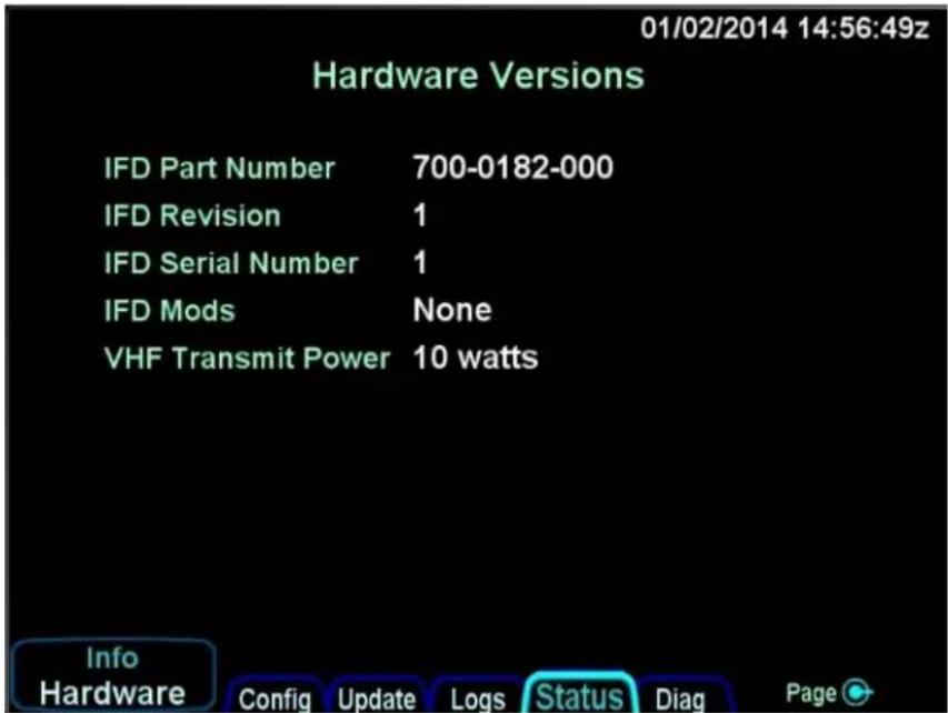
Figure 34 Hardware Version Page

Figure 35 Software Version Page
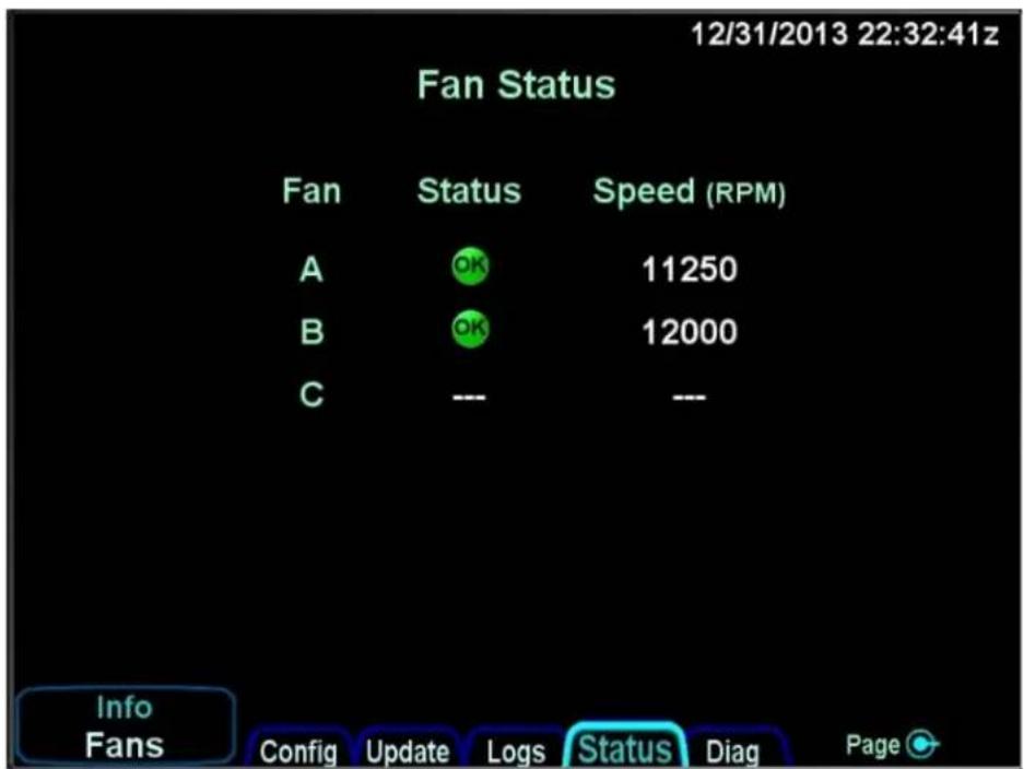
Figure 36 Fan Status Page

bar
IFD Temperatures | Source | Temp (°C) | |---|---| | ACR | 0.0 | | LIO 1 | 0.0 | | LIO 2 | 0.0 | | LIO 3 | 0.0 | | VHF DDCN | 0.0 | | VHF DDCC | 0.0 | | VHF BF | 0.0 | | VHF Tx | 0.0 | | VHF Rf | 0.0 | | FPSM LED | 0.0 | | FPSM 1 | 0.0 | | FPSM 2 | 0.0 | | FPSM 3 | 0.0 | Info Temps Config Update Logs Status Diag PageFigure 37 IFD Temperature Status Page
The pages on the "Diag" tab are for Avidyne Service Center diagnostics purposes and are not described in this manual.
7.6 Checkout
After configuring the IFD, the following post-installation tasks should be performed.
7.6.1 Database Check
Verify the Navigation, Chart, and Obstacle databases are up to date. If the databases need to be updated, reference the IFD Pilot's Guide or Section 10.1 for update procedures.
7.6.2 Airplane Flight Supplement Check
Complete and install the IFD Airplane Flight Manual Supplement in the aircraft's Flight Manual or Pilot's Operating Manual.
7.6.3 Instructions for Continued Airworthiness
Complete and install the IFD Instruction for Continued Airworthiness in the aircraft maintenance records.
7.6.4 Aircraft Weight and Balance
Update the Aircraft's Weight and Balance in the aircraft records.
For those installations where an IFD5XX/4XX is replacing a similar equipped GNS530 or GNS430 (a like variant) no weight and balance must actually be performed. If a GPS only Garmin unit is being replaced with a full featured IFD5XX/4XX, the weight change is more than one pound and a weight and balance must be prepared.
Since a full featured IFD5XX/4XX is within 5% of the weight of the removed GNS530/430 (less than 1 pound difference), no new weight and balance must actually be performed according to AC 43.13-1B Change 1 Acceptable Methods, Techniques, and Practices Aircraft Inspection and Repair (Chapter 10) and AC 120-27E Aircraft Weight and Balance Control.
7.6.5 Electrical Load Analysis
Verify the aircraft's electrical load is within limits, reference Section 4.10.
7.6.6 GPS Signal Acquisition
After installation, position the aircraft outside with clear unobstructed view of the sky. Verify the IFD acquires and calculates a GPS position. Verify no interference from other aircraft equipment is observed (e.g. TCAS, SATCOM, etc)
7.6.7 VHF COM Checkout
Note: This section is not applicable for IFD510/545/410.
7.6.7.1 VHF COM Interference
After installation, the VHF Communication should be tested. In 1 MHz increments between 118-136.000 MHz, transmit for 35 seconds on each frequency. Verify no interference between VHF Comm and other aircraft systems.
Evaluate the GPS system on the following frequencies. The GPS system should not experience complete signal loss on when transmitting on the VHF Comm.
25 kHz channels
• 121.150
• 121.175
• 121.200
• 131.250
• 131.275
• 131.300
8.33 kHz channels
• 121.185
• 121.190
• 130.285
• 131.290
•
7.6.7.2 VHF Antenna Checkout
Verify the VSWR is less than 2:1 through the entire frequency band. This can be verified using an aviation navigation test set (e.g. IFR 4000 or similar test equipment). VSWR higher than 2:1 will have reduced VHF Com performance. If >2:1 VSWR, verify in-flight performance is acceptable.
7.6.7.3 Receiver/Transmitter Operation
Test VHF Com's ability to receive and transmit to another VHF Com station. Verify using a low/middle/high frequency.
7.6.8 VOR/LOC/GS Checkout
Note: This section is not applicable for IFD510/545/410.
If installed, test the VOR/LOC/GS system using a local frequency or test set. Verify the OBS (selected course) is functioning, CDI/HSI/PFD is indicating correctly, and NAV audio is received. Also, verify no EMI on the VOR/LOC/GS system.
7.6.9 Autopilot
If the IFD can be coupled to an Autopilot system, verify the Autopilot is operating correctly with the IFD as the navigation source.
7.6.10 Magnetic Compass Swing
After installation and EMI checks are complete, perform a magnetic compass “swing” in accordance with the aircraft maintenance manual for updating the heading correction card in accordance with 14 CFR 23.1327 and 23.1547.
7.6.11 IFD Bezel and Display Lighting
Verify the Bezel and Display Lighting for the IFD can be set to an appropriate level for Day and Night flight conditions. Likewise, verify any external HSI/CDIs can be properly adjusted for day and night lighting conditions.
7.6.12 External Annunciators and Switches
If installed, verify external annunciators and switches are operating correctly. Verify the external annunciator lighting can be adjusted for Day and Night flight conditions (Bright and Dim setting, but never off). Verify all external switches are functioning correctly.
7.6.13 Placards
Verify all circuit breaker(s), switches, and limitation placards (if needed) are installed.
If required per Section 2.1.1, there must be a placard in clear view of the pilot that specifies the kind of operations to which the operation of the airplane is limited or from which it is prohibited under 14 CFR 23.1525. The limitation placard must be installed in a conspicuous place in the Pilot's field of view. The placard text height must be a minimum of 0.10 inches in contrasting color to the surrounding area. The text must be high-quality solid-color font of at least 300 DPI (dots per inch). The placard must not be easily disfigured, erased, or obscured.
7.6.14 Self-test Page
For the duration that the notification of legal rights page is displayed during normal power up on the ground, all remote annunciator lamps are lit up and the system generates a specific set of electrical outputs for the purpose of self-test and troubleshooting. The table below defines the outputs transmitted during this time.
| Parameter | Self-test Value |
| Course Deviation | Half-scale left deviation, TO indication, flag stowed |
| Glideslope/Vertical Deviation | Half-scale up deviation, flag stowed |
| Annunciators | All on |
| Bearing to Waypoint (RMI) | 135° |
| Selected Course (OBS) | 150° when interfaced to an HSI with course pointer |
| Desired Track | 150° |
| Distance To Go | 10.0 NM |
| Time To Go | 4 minutes |
| Active Waypoint | “AVDYN” |
| Groundspeed | 150 knots |
| Present Position | N39°04.05', W094°53.86' |
| Waypoint Alert | Active |
| Phase of Flight | Enroute |
| Message Alert | Active |
| GPS Integrity | Invalid |
| Roll Steering (if applicable) | Flight Director commands 0° bank (level flight) for 5 seconds; commands increasing right bank at 1°/second for 5 seconds; commands 5° right bank for 5 seconds; commands decreasing right bank at 1°/second for 5 seconds, until command is 0° bank again. This cycle repeats continuously. |
Table 142 Self-test Output
7.6.15 Dual IFD Configuration
If installing two IFD units, verify duplex communication between the two units. Reference Section 3.3.8 and 7.3 for limitations and configuration.
7.6.16 Heading Interface Check
Verify the IFD is receiving heading information from an external source. This can be verified on the Main Input Page in maintenance mode, reference Section 7.5.6. If power is removed from the external heading source, the Main Input Page will display dashed lines for heading. Note: If the IFD is connected to a Primary Flight Display, it must be turned off before performing this check.
7.6.17 ADS-B Output
If the IFD is connected to ADS-B out transponder, verify the position information transmitted is correct per 14 CFR 91.227. Also, if using the IFD for transponder Mode-C altitude information, verify the transponder is using the correct altitude source from the IFD, reference Section 6.12.
7.6.18 Fixed Wing TAWS Checkout (if enabled)
7.6.18.1 TAWS System Self-Test
- Press the AUX key on the bezel.
- Press the left side of the AUX key until the "SYS" tab is selected.
- Press the LSK labeled "Select" until "GPS" is displayed.
- Ensure "SBAS" is displayed beside "NAV MODE".
Note:
TAWS operation, to include the internal self-test, is dependent upon the IFD achieving SBAS. TAWS will have no functionality in any other GPS state. GPS antennas must have a clear line of sight with the sky in an open area to achieve SBAS. It can take the IFD three to four minutes to achieve SBAS.
- Press the left side of the AUX key until the "AUDIO" tab is selected.
- Twist the bottom right outer knob to highlight "Aural Alert".
- Use the bottom right inner knob to adjust the "Aural Alert" volume output.
a. The volume should be adjusted so that audible alerts can be clearly heard in a noise intensive environment (i.e., Engine(s) running).
- Press the MAP key on the bezel.
- Press the left side of the MAP key until the "TAWS" tab is selected.
- On the TAWS screen, press the SELF TEST button.
- Listen for the aural annunciation "TAWS System Test OK", this indicates the system has passed.
7.6.18.2 TAWS System Failure Mode Test
- Ensure the TAWS System is operational per the test listed in 7.6.18.2
- Block the GPS reception by any means available
- Once the IFD GPS signal is degraded, verify the IFD issues a TAWS FAIL CAS message along with an aural chime
a. If external annunciators are installed, the TAWS NOT AVAILABLE light should come on at this time.
b. Acknowledging the CAS message by pressing the CAS message on the screen, or by pressing the CLR line select key will cancel the aural alert chime.
-
GPS degradation can be determined by receiving a GPS degraded CAS message on the IFD or manually by validating any GPS state other than SBAS is presented beside "NAV MODE" on the GPS status page.
-
Once the system has appropriately failed, allow the GPS to regain SBAS by removing the blocking apparatus ^6 . Ensure the TAWS Fail Annunciation clears
7.6.18.3 TAWS External Annunciator Test (If Installed)
The TAWS Annunciators will illuminate during the IFD start-up test.
Individual TAWS annunciators can also be tested separately via the Main Discrete Toggles in maintenance mode (See section 7.5.8 of this manual).
8. Flight Checks
The IFD must be flight tested to verify the installation is operating properly. The following items should be tested in flight to verify the IFD function.
8.1 GPS Verification
Verify the following in flight:
- Verify the GPS reception during all phases of flight. (e.g., bank angles of up to 30 degrees and pitch angles associated with take-off, departures, landing and missed approaches)
-
Verify the following GPS/FMS operation:
-
Hold at a designated waypoint
- Intercept and track to or from a waypoint on a selected course
- Waypoint sequencing
- Verify the overall operation of procedures or paths
- Selection of an approach
- Evaluate the display of navigation parameters on the flight instruments (PFD, HSI, CDI) is correct
- Verify annunciation is correct and in the Pilot's field of view
8.2 VHF COM Flight Check
Note: This section is not applicable for IFD510/545/410.
Verify in-flight the IFD VHF communication transceiver in the high, mid, and low frequency ranges. Verify the VHF at least 50 nautical miles and at an appropriate altitude.
8.3 VOR Flight Checks
Note: This section is not applicable for IFD510/545/410.
Verify in-flight the IFD VHF navigation receiver by tuning a local VOR station within 50 nautical miles. Verify the audio tone is heard and course deviation information and flag information are correct.
8.4 ILS Flight Checks
Note: This section is not applicable for IFD510/545/410.
Verify in-flight the IFD VHF navigation receiver by tuning an airport with an ILS. Verify the NAV ID audio tone is heard and the course deviation and flag information are correct.
8.5 Autopilot Checks
Verify the IFD interface to the autopilot is correct. Reference the Autopilot Manual installation/maintenance manual for test procedures. Verify the following functions:
- Evaluate the steering response while in Flight Director (FD) and when the autopilot is coupled
- Execute several fly-by-turns with varying wind conditions for the FD and autopilot
- Evaluate the autopilot's response to a GNSS fault (e.g., pulling the IFD Circuit Breakers)
8.6 Sensors Verification
Verify the IFD interface to other aircraft sensors are operating correctly (e.g., Traffic, Lightning, Weather, etc).
8.7 Fixed Wing TAWS Checks (if enabled)
Verify the IFD TAWS system passes self-test. Ensure that on approach, the pilot is able to easily hear and clearly discern the "500 ft Callout"
9. Glove Validation Procedures
Many types of gloves can be used with the IFD touch screen display. The key parameter for the effectiveness of a glove with touch screen is the distance between the finger and the glass and to a lesser extent, the type of material separating the skin from the glass. The thinner the glove or the more compatible the material (e.g. leather, fine cotton, etc), the greater the likelihood of success will be. Likewise, the more surface area that comes in contact with the glass, the greater the success may be. Each glove must be qualified for compatibility with the display and those glove calibration procedures (specific to the glove and the pilot combination) are immediately below. If all verification steps are marked as a "Pass" then the glove/pilot combination is considered to be a qualified pair.
| Pilot Name | ||
| Description of Glove | ||
| Verification Step | Circle | one |
| Touch the standby frequency window and verify a virtual keyboard is displayed. | Pass | Fail |
| Type 121.7, press the "ENTER" button on the virtual keyboard and confirm 121.700 is the displayed frequency in the #1 Standby Com window. | Pass | Fail |
| Press each of the page tabs displayed on the present page and verify the IFD changes to the selected tab. | Pass | Fail |
| With the FMS FPL tab displayed, use touch to type in a typical flight plan and verify that all entries were recognized. | Pass | Fail |
| With the Map page and tab displayed, attempt to pan the map. | Pass | Fail |
| With the Map page and tab displayed, attempt to pinch zoom (in or out) the map to produce a range change. | Pass | Fail |
| With the Map page and tab displayed, attempt to graphically flight plan ("rubber band") and verify the intended change was made. | Pass | Fail |
| Press the "Freq" function key on the bezel and then double tap a frequency from the list to place it into the #1 standby slot. | Pass | Fail |
Table 143 Glove Validation Procedure
10. Software and Database Update Procedures
10.1 Data Updates
Periodic updates to navigation data, charts data, and obstacle data are all made through the USB port on the front of each IFD. Updates must be performed in accordance with 14 CFR Part 43, Appendix A (c) and FAA AC 20-153() paragraph 11.
The table below summarizes the databases update periods:
| Database | Update Cycle | Comments & Source |
| Chart Data | 14 days | Expiration watermark displayed after 14 days indefinitely until data updated (Jeppesen) (N/A for IFD4XX) |
| Nav Data | 28 days | Airport, airway, navaid, airspace, and FMS data (Jeppesen) |
| Obstacle Data | 56 days | Displayed on map and used for TA and FLTA functions (Jeppesen) |
| Terrain Data | As required | Displayed on map and used for TA and FLTA functions. The IFD is shipped from the factory with this database already loaded and updates are anticipated to be a rare occurrence. |
Table 144 Database Update Cycle
In the event the terrain data ever needs updating, this is also performed through the front panel USB port.
Use one of the formatted fobs supplied by Avidyne (marked by the Avidyne logo printed on one side). In the event one of those fobs are not available, either call Avidyne for a replacement fob (a nominal fee will be charged) or purchase a replacement through other means. Most USB drives that can be formatted using FAT32 will be acceptable.
To perform a data update, ensure the data to be updated is placed onto one of the acceptable USB fobs. Carefully insert the USB fob into the IFD USB slot while power is turned off. When the IFD is powered up it should start in maintenance mode. If the IFD does not start in maintenance mode, select the "Setup" tab of the SYS page and then pick the "Update Databases" LSK.
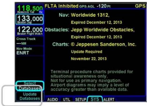
Figure 38 Update Databases LSK
You will be prompted to "Confirm" or "Cancel". Assuming you selected "Confirm", you should see a dialog box presented in the middle of the screen and all uploadable files on that fob will be individually listed and check marks may be visible next to each file name.

Figure 39 Confirm and Cancel LSK
Use the "Select All", "Un-select All" LSKs and the lower right IFD knob twist to scroll and push to select as required to ensure check marks are associated with all the desired files to upload to the IFD. Now press the "Proceed" LSK to begin the file upload.
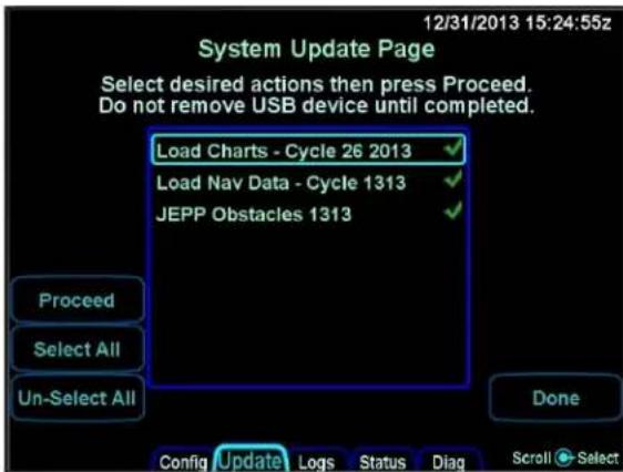
Figure 40 LSK Options
A progress bar will be presented to help provide an idea of how much longer the upload will take.

Figure 41 Progress Bar
Typical upload times are:
• Worldwide Obstacles (1.5 MB) - 5 sec
• Eastern US Charts (100 MB) - 3 min
• US Charts (180 MB) - 5 12 min
• Worldwide Charts (430 MB) - 13 min
• US Nav Data (8 MB) - 3 12 min
• Europe Nav Data (10 MB) - 2 12 min
• Australian Nav Data (1.5 MB) - 30 sec
• Worldwide Nav Data (15 MB) - 7 Min
For multiple IFD installations, the database uploads must be performed individually for each IFD to be updated.
Due to some of the upload durations, Avidyne recommends creating a fob for each IFD to be updated so that the updates can happen in parallel and not stacked serially, thereby extending the overall time to accomplish a full update.
A clear indication is presented when the data uploads have been completed. Likewise, if the USB fob was removed prior to finishing the data upload, an error message will be presented and the entire process will need to be manually restarted once the fob is reinserted in the IFD.
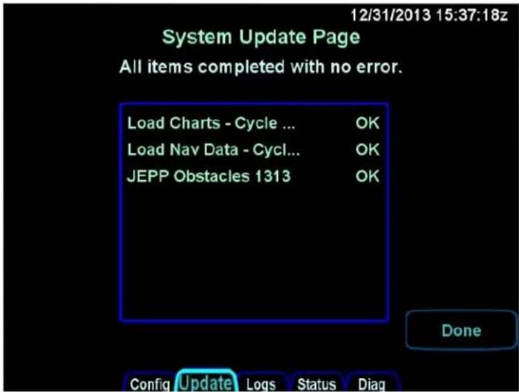
Figure 42 Update Complete Indication
When you are all done press the "Done" LSK, which will restart the IFD into flight mode. Remove the USB fob and perform a normal start up. It is highly recommended to verify the data was updated from the "Setup" LSK of the SYSTEM tab on the AUX page.
If an IFD is in normal operating mode (not maintenance mode), the presence of a USB fob is ignored.
10.2 Datalogs Download
There is extensive data-logging that is automatically done on all IFDs. These datalogs can be accessed post-flight and used for a number of purposes.
There are five types of datalogs employed in the IFDs:
- System Log - This log provides an in-depth record of the navigation state. From this log, you can re-create many aspects of the FMS output and IFD state. It logs at a rate of approximately 1Hz.
- Flight Log – This log provides a detailed record of your aircraft state as measured by the various IFD sensors. It logs at a rate of approximately 5Hz.
- Engine Log - This log provides details on fuel flow sensor data (if configured). It logs at a rate of approximately 14 Hz.
- Event Log – This log contains miscellaneous data such as all alerts, keystrokes, flight plan data, system status and error messages, etc. It is designed to be diagnostics log for Avidyne Service Center technicians and not expected to be used by owners/operators. It logs at an on-condition rate.
- Voltage Log - This log contains internal diagnostic data such as the voltages and currents on sub-system boards, temperatures and internal fan status. It logs at a rate of approximately 1Hz.
- Download Configuration Info - This log contains the system configuration for the unit.
- GPS Log - This log contains detailed internal state data for the GPS.
The "Download Logs" LSK is presented when "Software" is selected on the SYS tab and the system is not in-air. When the "Download Logs" LSK is pressed, a pair of Confirm/Cancel LSKs are presented. Selecting Confirm will launch the Maintenance Mode of the IFD. From Maintenance Mode, press the right side of the AUX page function key to select the "Logs" tab. Ensure a USB fob is inserted in the IFD front bezel USB port and then use a combination of the left side LSKs and the bottom right IFD knob to select the desired combination of logs and type of action to perform.

Figure 43 Datalogs Download Page
Pressing the "Proceed" LSK will immediately start downloading all logs listed in the center of the page with green check marks adjacent to them. If only a subset of the logs are to be downloaded, use the "Un-Select All" LSK to deselect all logs and then use the bottom right IFD knob to highlight the desired log and push in to generated a green check mark.
The "Logs" LSK on that Maintenance Mode page provides two options for downloading this data via dedicated LSKs. The first option ("Since Last") downloads the data logged since the last time a download was completed. Since the logs contain a large amount of data, the Since Last option will be a quicker option in almost every case. The second option ("Full") allows a download of all data logs onto the USB fob. The Full option can take up to 45 minutes to an hour to complete.
Download times are highly dependent on the number and types of logs being downloaded and how long it's been since the last download and whether you are downloading Since Last or Full. Times can range from a few seconds to more than 45 minutes. The more often logs are downloaded, the shorter the download times will be.
In order to provide an indication of download progress, a progress bar will be presented with both a symbolic aircraft indicating download in progress and a % complete estimate. The files to be downloaded can have one of several states - "OK", "In progress...", "Pending", "Skipped", "Active", "Failed".
When downloaded to the USB fob, the data logs will be saved in .csv files. This can be imported into newer versions of Microsoft Excel into a table format. The data can then be plotted or analyzed by several 3rd party tools. Note that files can easily contain 50MB or more of data.
10.3 Software Update
The following procedures should be followed when performing optional or mandatory software change to the IFD System:
- Acquire the software image and associated loading procedure from the manufacturer.
- Verify the software part number configuration before and after maintenance is performed on the airborne equipment using the loading procedure instructions.
- It is the responsibility of maintenance personnel to ensure the identified part is recorded in the necessary maintenance logs.
- It is the maintenance personnel's responsibility to ensure that the software part identification has been logged. When new software is loaded into the unit, the correct software part number should be verified according to the instructions accompanying the software change before the unit is returned to service. Hardware versions are identified on the data label by a Rev number following the main part number.
Changes to software part number, version, and/or operational characteristics should be reflected in the Operator's Manual, Aircraft Flight Manual, Aircraft Flight Manual Supplement, and/or any other appropriate document.
11. Periodic Maintenance
The IFD does not require any periodic or preventative maintenance. Maintenance on the IFD is on condition.
11.1 Equipment Calibration
The IFD has no required servicing tasks.
11.2 VOR Checks
Every 30 days, verify the limits of the VOR per 14 CFR §91.171. Only required for IFR operations. (N/A for IFD510/545/410 and Atlas FMS Only units)
11.3 Cleaning
The front display and bezel may require cleaning periodically, reference Section 13.
12. Factory Service Policies and Procedures
12.1 Technical Support
Avidyne's website contains information that may assist the operator and installer with questions or problems with their Avidyne IFD5XX/IFD4XX/ATLAS. Technical support questions may be submitted, via the following:
• Email: techsupport@avidyne.com
• Fax: 321-751-8435
• Voice: 1-888-723-7592 Toll Free USA.
• Voice +1-321-751-8520 Option 3 Outside the USA
• Internet: www.Avidyne.com
- Dealer Knowledge Base*https://techsupport.avidyne.com/home/
* Caution, Verify with this document that all of the devices shown in the Dealer Knowledge Base are FAA approved to interface with the IFDXXX or Atlas series of navigators.
Please include the part number, revision number and serial number of the unit in all correspondences. For problem reporting, please provide as many details associated with the problem as possible.
An Avidyne Technical Support Representative will respond as soon as possible. Avidyne business hours are: Monday through Friday: 8:00 AM to 5:00 PM Eastern Time For After Hours AOG Technical Support, is available via the following: AOG Support: 877-900-4AOG (4264)
12.2 General Service Procedures
Repair of the IFD/Atlas are performed at the authorized Part 145 service center located at the Avidyne factory.
Prior to returning a unit for service, contact Avidyne at , techsupport@avidyne.com or 1-888-723-7592 to obtain a Return Merchandise Authorization (RMA) number.
When calling or emailing for product-related help, please have the following information available:
- Customer Name/Account Information
- IFD Serial Number. This number is displayed on the Software Status page available on the SYS tab. See image below. Alternatively, the number is printed on the TSO label of the IFD unit.
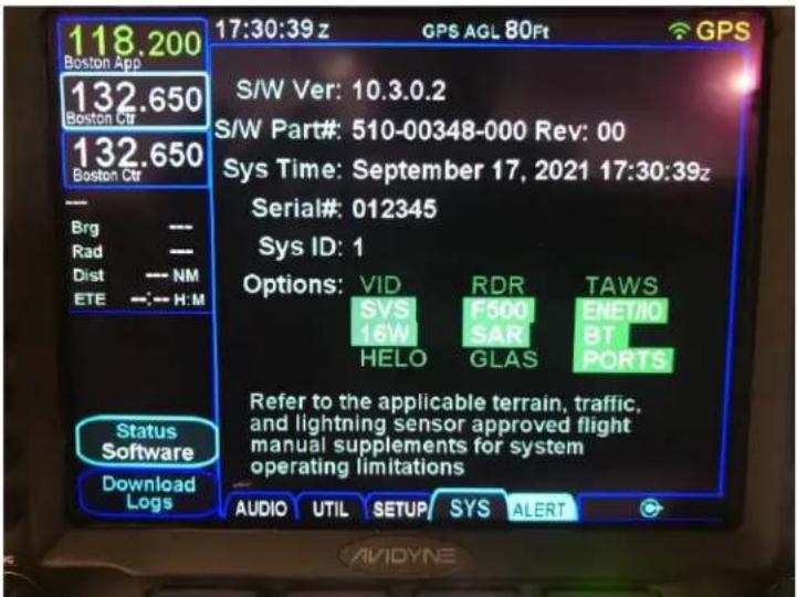
-
IFD Software Part Numbers: Press the "AUX" page function key and then tab over to the "SYS" tab. Record the "Software Version" and the "Flight Software Part Number". Also make a note of any other yellow text on that page.
-
Be prepared to download the aircraft flight logs and email/transmit them to Avidyne Technical Support.
13. Bezel and Display Cleaning
If the IFD screen should become dirty due to fingerprints or dust, clean the screen using the following materials and methods:
A clean, soft lint-free cloth such as 3M Ultra-Brite Cloth #2011 or similar.
A cleaning solution composed of a 1:1 ratio of de-ionized water and isopropyl alcohol (IPA). Use caution, as it may be flammable. Always apply the cleaning solution directly on the cloth. Never spray cleaner directly on the screen.
In general, isopropyl alcohol is a safe and effective cleaner. Methanol and most acidic solutions can be toxic or damaging to glass coatings if misused.
Excessive or unnecessary cleaning should be avoided to prevent damage to the coated optical filter surfaces. Never allow excess amounts of cleaning agents to dry if they have formed into pools, streaks or droplets to help avoid spotting of the glass surface.
The use of any 3rd party screen protector, especially those that adhere directly to the IFD display glass, is not endorsed by Avidyne due to the touch-screen nature of the display and may void the warranty for any display related issue.
Appendix A: Environmental Qualification Form
IFD540, IFD510, IFD440, IFD410
| Environmental Tests | RTCA/DO-160G Section | Test Category |
| Temperature and Altitude | 4.0 | |
| Low Temp | 4.5.2 | Equipment qualified to Category C1 |
| High Temp | 4.5.3 & 4.5.4 | Equipment qualified to Category C1 |
| In-Flight Loss of Cooling | 4.5.5 | Equipment qualified to Category W |
| Altitude | 4.6.1 | Equipment qualified to Category C1 |
| Decompression | 4.6.2 | Equipment qualified to +55,000 Ft. |
| Overpressure | 4.6.3 | Equipment qualified to -15,000 Ft. |
| Temperature Variation | 5 | Equipment qualified to Category B |
| Humidity | 6 | Equipment qualified to Category A |
| Operational Shocks & Crash Safety | 7 | Equipment qualified to Category E |
| Vibration | 8 | Equipment qualified to Category S, Curves B and M, Category U, Curve G |
| Explosive Atmosphere | 9 | Category X, no test performed |
| Waterproofness | 10 | Category X, no test performed |
| Fluids Susceptibility | 11 | Category X, no test performed |
| Sand and Dust | 12 | Category X, no test performed |
| Fungus Resistance | 13 | Category X, no test performed |
| Salt Spray | 14 | Category X, no test performed |
| Magnetic Effects | 15 | Equipment qualified to Class Z |
| Power Input | 16 | Equipment qualified to Category B |
| Voltage Spike | 17 | Equipment qualified to Category A |
| Audio Frequency Conducted Susceptibility | 18 | Equipment qualified to Category B |
| Induced Signal Susceptibility | 19 | Equipment qualified to Category ZC |
| Radio Frequency Susceptibility | 20 | Equipment qualified to Category W (conducted)/WR (radiated) |
| Emission of Radio Frequency Energy | 21 | Equipment qualified to Category M |
| Lightning Induced Transient Susceptibility | 22 | Category B4HZL4 (Power) and B3K4L4 (All other I/O) |
| Lightning Direct Effects | 23 | Category X, no test performed |
| Icing | 24 | Category X, no test performed |
| Electrostatic Discharge | 25 | Equipment qualified to Category A |
| Fire and Flammability | 26 | Category X, no test performed |
Table 145 Environmental Qualification Form - IFD540/510/440/410
IFD550, IFD545
(Low Temp and Vibration Categories Differ From Table 145)
| Environmental Tests | RTCA/DO-160G Section | Test Category |
| Temperature and Altitude | 4.0 | |
| Low Temp | 4.5.2 | Equipment qualified to Category X (non-standard category) Equipment tested to C1 with Ground Survival Low limited to -40C |
| High Temp | 4.5.3 & 4.5.4 | Equipment qualified to Category C1 |
| In-Flight Loss of Cooling | 4.5.5 | Equipment qualified to Category W |
| Altitude | 4.6.1 | Equipment qualified to Category C1 |
| Decompression | 4.6.2 | Equipment qualified to +55,000 Ft. |
| Overpressure | 4.6.3 | Equipment qualified to -15,000 Ft. |
| Temperature Variation | 5 | Equipment qualified to Category B |
| Humidity | 6 | Equipment qualified to Category A |
| Operational Shocks & Crash Safety | 7 | Equipment qualified to Category E |
| Vibration | 8 | Equipment qualified to Category S, Curves B and M |
| Explosive Atmosphere | 9 | Category X, no test performed |
| Waterproofness | 10 | Category X, no test performed |
| Fluids Susceptibility | 11 | Category X, no test performed |
| Sand and Dust | 12 | Category X, no test performed |
| Fungus Resistance | 13 | Category X, no test performed |
| Salt Spray | 14 | Category X, no test performed |
| Magnetic Effects | 15 | Equipment qualified to Class Z |
| Power Input | 16 | Equipment qualified to Category B |
| Voltage Spike | 17 | Equipment qualified to Category A |
| Audio Frequency Conducted Susceptibility | 18 | Equipment qualified to Category B |
| Induced Signal Susceptibility | 19 | Equipment qualified to Category ZC |
| Radio Frequency Susceptibility | 20 | Equipment qualified to Category W (conducted)/WR (radiated) |
| Emission of Radio Frequency Energy | 21 | Equipment qualified to Category M |
| Lightning Induced Transient Susceptibility | 22 | Category B4HZL4 (Power) and B3K4L4 (All other I/O) |
| Lightning Direct Effects | 23 | Category X, no test performed |
| Icing | 24 | Category X, no test performed |
| Electrostatic Discharge | 25 | Equipment qualified to Category A |
| Fire and Flammability | 26 | Category X, no test performed |
Table 146 Environmental Qualification Form - IFD550/545
ATLAS
| Environmental Tests | RTCA/DO-160G Section | Test Category |
| Temperature and Altitude | 4.0 | |
| Low Temp | 4.5.1 & 4.5.2 | Equipment qualified to Category X (non-standard category) Equipment tested to C1 with Ground Survival Low limited to -40C |
| High Temp | 4.5.3 & 4.5.4 | Equipment qualified to Category C1 |
| In-Flight Loss of Cooling | 4.5.5 | Equipment qualified to Category W |
| Altitude | 4.6.1 | Equipment qualified to Category C1 |
| Decompression | 4.6.2 | Equipment qualified to +55,000 Ft. |
| Overpressure | 4.6.3 | Equipment qualified to -15,000 Ft. |
| Temperature Variation | 5 | Equipment qualified to Category B |
| Humidity | 6 | Equipment qualified to Category A |
| Operational Shocks & Crash Safety | 7 | Equipment qualified to Category E |
| Vibration | 8 | Equipment qualified to Category S, Curves B and M, Category H, Curve R |
| Explosive Atmosphere | 9 | Category X, no test performed |
| Waterproofness | 10 | Category X, no test performed |
| Fluids Susceptibility | 11 | Category X, no test performed |
| Sand and Dust | 12 | Category X, no test performed |
| Fungus Resistance | 13 | Category X, no test performed |
| Salt Spray | 14 | Category X, no test performed |
| Magnetic Effects | 15 | Equipment qualified to Class Z |
| Power Input | 16 | Equipment qualified to Category B |
| Voltage Spike | 17 | Equipment qualified to Category A |
| Audio Frequency Conducted Susceptibility | 18 | Equipment qualified to Category B |
| Induced Signal Susceptibility | 19 | Equipment qualified to Category ZC |
| Radio Frequency Susceptibility | 20 | Equipment qualified to Category W (conducted)/WR (radiated) |
| Emission of Radio Frequency Energy | 21 | Equipment qualified to Category M |
| Lightning Induced Transient Susceptibility | 22 | Category B4HZL4 (Power) and B3K4L4 (All other I/O) |
| Lightning Direct Effects | 23 | Category X, no test performed |
| Icing | 24 | Category X, no test performed |
| Electrostatic Discharge | 25 | Equipment qualified to Category A |
| Fire and Flammability | 26 | Category X, no test performed |
Table 147 Environmental Qualification Form - Atlas
Appendix B: STC Permission
Avidyne Corporation hereby grants to all National Aviation Authorities (FAA, CAA, JAA, etc) approved installers the use of data from STC SA00343BO (Part 23 Aircraft) or STC ST00411BO (Part 25 Aircraft) to install the Avidyne IFD5XX / ATLAS System. This also includes any international validations of the STC (e.g. EASA, ANAC, etc). Copies of the STC data are available on the Avidyne Dealer Website or upon request. The latest data revisions are listed in Avidyne 700-00182-XXX/700-00179-XXX Master Document List, AVIFD-306 STC SA00343BO (Part 23 Aircraft), or AVIFD-568 STC ST00411BO (Part 25 Aircraft)
Installers must abide by the conditions and limitations stated in both the STC and in the Installation Manual in order to maintain compliance. The use of this data by itself does not constitute installation approval.
Appendix C: Mechanical Drawings
Figure C - 1 IFD5XX Tray Installation ....201
Figure C - 2 IFD4XX Tray Installation ....202
Figure C - 3 IFD5XX Instrument Panel Cutout....203
Figure C - 4 IFD4XX Instrument Panel Cutout....204
Figure C - 5 Atlas Physical Dimensions ....205
Figure C - 6 Typical GPS Antenna Installation....206
Figure C - 7 AT-575 GPS Antenna Hole Pattern....206
Figure C - 8 AV-801 GPS Antenna Hole Pattern ....207
Figure C - 9 Typical GPS Antenna Doubler Installation ....208
Figure C - 10 Typical GPS Antenna Doubler ....209

Figure C - 1 IFD5XX Tray Installation

Figure C - 2 IFD4XX Tray Installation
INSTRUMENT PANEL CUTOUT
UNIT INSTALLED FROM THE FRONT OF
INSTRUMENT PANEL
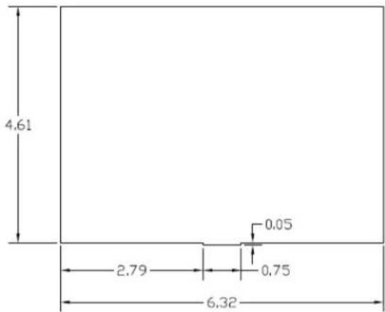
INSTRUMENT PANEL CUTOUT
UNIT INSTALLED FROM THE REAR OF THE
INSTRUMENT PANEL
MAXIMUM PANEL THICKNESS ,125 INCHES

Figure C - 3 IFD5XX Instrument Panel Cutout
INSTRUMENT PANEL CUTOUT
UNIT INSTALLED FROM THE FRONT OF
INSTRUMENT PANEL
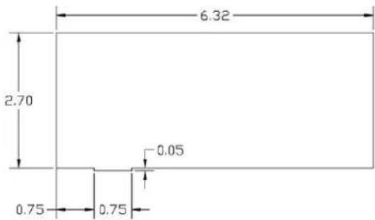
INSTRUMENT PANEL CUTOUT
UNIT INSTALLED FROM THE REAR OF THE
INSTRUMENT PANEL
MAXIMUM PANEL THICKNESS .125 INCHES

Figure C - 4 IFD4XX Instrument Panel Cutout


Figure C - 5 Atlas Physical Dimensions
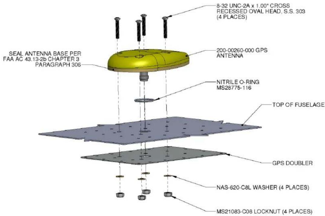
Figure C - 6 Typical GPS Antenna Installation

Figure C - 7 AT-575 GPS Antenna Hole Pattern
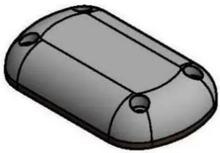
natural_image
3D rendering of a rounded rectangular electronic component with four circular holes (no text or symbols)

Figure C - 8 AV-801 GPS Antenna Hole Pattern


Reference Table Below for Rivet type
Figure C - 9 Typical GPS Antenna Doubler Installation
| Fuselage Skin Thickness | Adjacent Structure † Rivet Type | Doubler Thickness | Outer Rivet Row in Doubler | Inner Four Rivet in Doubler |
| 0.016" - 0.025" | Dimpled skin / Countersunk Rivets | 0.020" | MS20426AD3 (Double Dimple) | MS20426AD3 (Double Dimple) |
| 0.016" - 0.025" | Protruding Head Rivets | 0.020" | MS20470AD3 | MS20426AD3 (Double Dimple) |
| 0.032" - 0.050" | Countersunk Skin / Countersunk Rivets | 0.032" | NAS1097AD4 (Countersunk) | NAS1097AD4 (Countersunk) |
| 0.032" - 0.050" | Protruding Head Rivets | 0.032" | MS20470AD4 | NAS1097AD4 (Countersunk) |
Table 148 Rivet/ Doubler Selection
‡ Rivet type is dependent on the type of rivets in the adjacent fuselage structure. If the adjacent rivets in the structure around the bay selected for the doubler installation are protruding head type, install MS20470AD rivets in the outer row of the doubler. If the adjacent rivets are countersunk or dimpled, install either MS20426AD or NAS1097AD rivets per the table above.
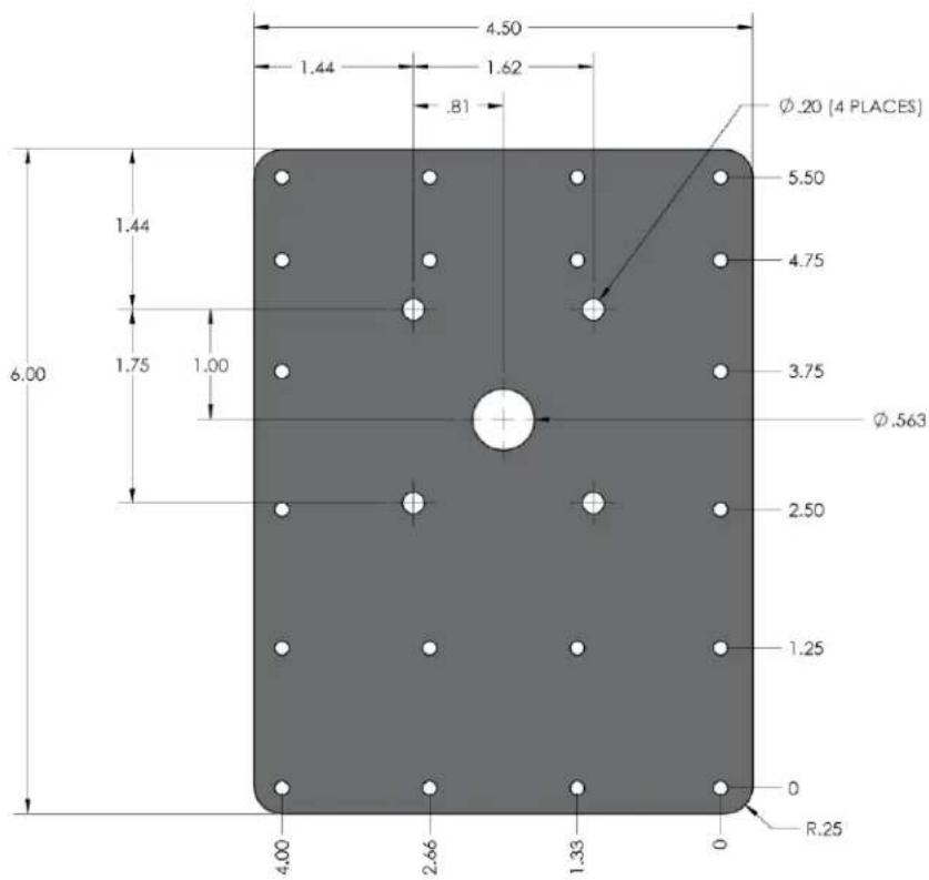
Figure C - 10 Typical GPS Antenna Doubler
Appendix D: Electrical Interface Drawings
Figure D - 1: Lighting, Power, and Antenna Interconnect....213
Figure D - 2: Blind Altitude Encoders Interconnect....216
Figure D - 3: RS-232 Serial Data Interconnect....217
Figure D - 4: EFIS Interconnect....219
Figure D - 5: Generic EFIS Interconnect ....220
Figure D - 6: EHSI ARINC 429 Interconnect, Dual IFD5XX/4XX, Sandel SN3308 Interconnect...221
Figure D - 8: ARINC 429/RS-232 Air Data/IRU/AHRS Interconnect ....223
Figure D - 9: Sandel SN3500 Interconnect....225
Figure D - 10: Traffic Advisory Interconnect ....226
Figure D - 10: Traffic Advisory Interconnect ....227
Figure D - 12: GTX 330 Interconnect....229
Figure D - 13: Terrain and Weather Interconnect....230
Figure D - 14: Weather Interconnect ....231
Figure D - 15: Audio Panel Interconnect....232
Figure D - 16: VOR/ILS Indicator Interconnect ....234
Figure D - 17: Main Indicator Interconnect....235
Figure D - 18 Main Indicator KI209 Interconnect....237
Figure D - 19: Main Indicator KI208A Interconnect....237
Figure D - 20: Main Indicator MD200-20X/-30X Interconnect....238
Figure D - 21: RMI/OBI Interconnect ....239
Figure D - 22: King Serial DME Tuning Interconnect, Panel Mount ....240
Figure D - 23: King Serial DME Tuning Interconnect, Remote Mount ....241
Figure D - 24: Parallel DME Tuning Interconnect....242
Figure D - 25: Parallel DME Tuning Interconnect....243
Figure D - 26: TAWS Interconnect....244
Figure D - 27: Autopilot Interconnect....245
Figure D - 28: Bendix/King Autopilot Interconnect....246
Figure D - 29: Century Autopilot Interconnect....247
Figure D - 30: Century Autopilot Interconnect....248
Figure D - 31: S-Tec Autopilot Interconnect....249
Figure D - 32: Collins Autopilot Interconnect....251
Figure D - 33: Bendix King KFC400 Autopilot Interconnect ....252
Figure D - 34: External Navigation Source and GPS Annunciators Interconnect....253
Figure D - 35: Switch Interconnect ....255
Figure D - 36: Garmin GAD 42 Interconnect ....256
Figure D - 37: Garmin G600 Interconnect....257
Figure D - 38: Avidyne Entegra Interconnect ....258
Figure D - 39: Avidyne EX500/600/5000 Interconnect....259
Figure D - 40: Aspen EFD1000 Interconnect (without ACU)....260
Figure D - 41: Aspen EFD1000 Interconnect (with ACU) ......261
Figure D - 42: Transponder Interconnect ....262
Figure D - 43: ELT Interconnect....263
Figure D - 44: Skytrax100B/200 (formerly MLB100) ADS-B IN Receiver Interconnect....264
Figure D - 45: RDR2000 Interconnect....265
Figure D - 46: RDS Radars Interconnect ....266
Figure D - 47: RDR2100/2060 Interconnect....267
Figure D - 48: MK VI and VIII EGPWS Interconnect....268
Figure D - 49: MK V, V-A, and VII EGPWS Interconnect....269
Figure D - 50: GTX 335 Interconnect....270
Figure D - 51: GTX 345 Interconnect ....271
Figure D - 52: GTX 330ES Interconnect....273
Figure D - 53: Garmin GTX 3000 Interconnect....274
Figure D - 54: Avidyne AXP322 Interconnect....275
Figure D - 55: Avidyne Dual AXP322 Interconnect....276
Figure D - 56: NXT 700 MST70B Transponder Interconnect ....277
Figure D - 57: Becker BXT 65XX Interconnect....278
Figure D - 58: FreeFlight FDL 978RX Interconnect ....279
Figure D - 59: GDL 88 Interconnect....280
Figure D - 60: Avidyne AXP340 Interconnect....281
Figure D - 61: XMD076 Interconnect....282
Figure D - 62: Single GDU700/1060 PFD Interconnect....283
Figure D - 63: Dual GDU700/1060 PFD Interconnect ....284
Figure D - 64: Garmin G5 EHSI Interconnect ....285
Figure D - 65: Garmin G5 EADI Interconnect....286
Figure D - 66: Garmin G5 EFIS Interconnect....287
Figure D - 67: NGT9000R Interconnect....288
Figure D - 68: KT-74 Interconnect....289
Figure D - 69: TDR-94 Interconnect....290
Figure D - 70: Garmin GI-275 Interconnect....291

flowchart
graph TD
    A["IFD"] --> B["AIRCRAFT POWER 1"]
    A --> C["AIRCRAFT POWER 2"]
    A --> D["AIRCRAFT GROUND"]
    A --> E["LIGHTING BUS HI"]
    A --> F["LIGHTING BUS LO"]
    B --> G["P1001"]
    C --> H["P1002"]
    D --> I["P1006"]
    E --> J["P1007"]
    F --> K["P1008"]
    G --> L["22 AWG"]
    G --> M["18 AWG"]
    G --> N["5A for 28VDC"]
    G --> O["7.5 for 14VDC"]
    H --> P["20 AWG"]
    H --> Q["18 AWG"]
    H --> R["20 AWG"]
    H --> S["18 AWG"]
    I --> T["22 AWG"]
    I --> U["20 AWG"]
    I --> V["22 AWG"]
    J --> W["VOR"]
    K --> X["G/S DIPLEXER"]
    L --> Y["GPS ANTENNA"]
    M --> Z["GPS ANTENNA"]
    N --> AA["COM ANTENNA"]
    O --> AB["COM ANTENNA"]
    P --> AC["NAV ANTENNA"]
    Q --> AD["NAV ANTENNA"]
    R --> AE["NAV ANTENNA"]
    S --> AF["NAV ANTENNA"]
    T --> AG["10A AIRCRAFT POWER"]
    U --> AH["12 AIRCRAFT POWER"]
    V --> AI["12 AIRCRAFT POWER"]
    W --> AJ["7 GPS ANTENNA"]
    X --> AK["9 GPS ANTENNA"]
    Y --> AL["12 GPS ANTENNA"]
    Z --> AM["12 GPS ANTENNA"]
    AA --> AN["12 GPS ANTENNA"]
    AB --> AO["12 GPS ANTENNA"]
Figure D - 1: Lighting, Power, and Antenna Interconnect

flowchart
graph TD
    A["IFD #1"] --> B["P1003"]
    A --> C["P1004"]
    A --> D["P1005"]
    A --> E["P1007"]
    F["GPS ANTENNA"] --> G["7"]
    H["COM ANTENNA"] --> I["8"]
    J["VOR/LOC ANTENNA"] --> K["9"]
    L["GLIDESLOPE ANTENNA"] --> M["10"]
    N["G/S 1 VOR 1 S NAV ANTENNAD"] --> O["11"]
    P["IFD #2"] --> Q["P1007"]
    P --> R["P1005"]
    P --> S["P1003"]
    T["GLIDESLOPE ANTENNA"] --> U["11"]
    V["VOR/LOC ANTENNA"] --> W["12"]
    X["GPS ANTENNA"] --> Y["7"]
    Z["COM ANTENNA"] --> AA["12"]
    AB["GPS ANTENNA 1"] --> AC["12"]
    AD["COM ANTENNA 1"] --> AE["12"]
    AF["GPS ANTENNA 2"] --> AG["12"]
    AH["COM ANTENNA 2"] --> AI["12"]
Figure D - 1: Lighting, Power, and Antenna Interconnect
NOTES:
-
ALL WIRES TO BE 24 AWG OR GREATER UNLESS OTHERWISE NOTED.
-
IF AIRCRAFT HAS MULTIPLE POWER BUSSES, IT IS RECOMENDED THAT IFD/ATLAS POWER CONNECTIONS BE CONNECTED AS DESCRIBED IN SECTION 4.
3 AIRCRAFT POWER INPUT TO THE IFD MAY BE 9-33 VDC.
-
THE IFD SHOULD BE CONFIGURED FOR THE CORRECT LIGHTING BUS VOLTAGE POST-INSTALLATION. NO DAMAGE WILL OCCUR IF THE UNIT IS CONFIGURED INCORRECTLY. IN ADDITION, LIGHTING CAN BE SET TO AUTOMATICALLY COMPENSATE FOR AMBIENT LIGHTING CONDITIONS USING ITS LIGHT SENSOR. A MANUAL LIGHTING CONTROL OPTION IS ALSO AVAILABLE. REFER TO THE POST-INSTALLATION CONFIGURATION PROCEDURE. LIGHTING BUS INPUTS ARE NOT DIFFERENTIAL. LIGHTING BUS LOW MUST BE TIED TO GROUND IN ALL CASES. FAILURE TO ADHERE TO THIS WILL RESULT IN DAMAGE TO THE IFD/ATLAS..
-
MAXIMUM ALLOWABLE WIRE GAUGE INTO P1002 PINS IS 20 AWG. top
6 THE AIRCRAFT POWER INPUT P1006-44 PROVIDES POWER FOR THE VOR/LOC SUPERFLAG (P1006-15) AND GLIDESLOPE SUPERFLAG (P1006-38) OUTPUTS. NO POWER CONNECTION IS REQUIRED ON P1006-44 IF THESE FLAG OUTPUTS ARE NOT USED.
- THE GPS ANTENNA COAXIAL CABLE MUST BE DOUBLE OR TRIPLE SHIELDED AND THE LOSS (INCLUDING CONNECTORS) MUST BE GREATER THAN 1.5 dB AND LESS THAN 6.5 dB.
8 COMMANT CI1125 DIPLEXER, OR EQUIVALENT, SHOULD BE USED.
9 COMMANT CI507 DIPLEXER, OR EQUIVALENT, SHOULD BE USED.
10 ACFT PWR 1 IS INTERNALLY DIODE ISOLATED FROM ACFT PWR 2. ONLY ONE POWER INPUT IS REQUIRED FOR NORMAL OPERATION.
FOR THE MAIN POWER INPUT, A 14VDC INSTALLATION REQUIRED TWO AIRCRAFT POWER IPUTS AND TWO AIRCAFT GROUND CONNECTIONS BE USED FOR EACH MAIN POWER INPUT USED. A 28VDC INSTALLATION REQUIRES A MINIMUM OF ONE POWER AND GROUND CONNECTION, BUT TWO ARE RECOMMENDED.

NOT APPLICABLE FOR IFD410/510/545, or Atlas FMS Only units
Figure D - 1: Lighting, Power, and Antenna Interconnect Page 3 of 3

NOTES:
- ALL WIRES TO BE 24 AWG OR GREATER UNLESS OTHERWISE NOTED.
- REFER TO MANUFACTURER'S DOCUMENTATION FOR COMPLETE PINOUT AND INTERCONNECT INFORMATION.

THIS ENCODER MAY ALSO BE CONNECTED VIA RS-232.
Figure D - 2: Blind Altitude Encoders Interconnect
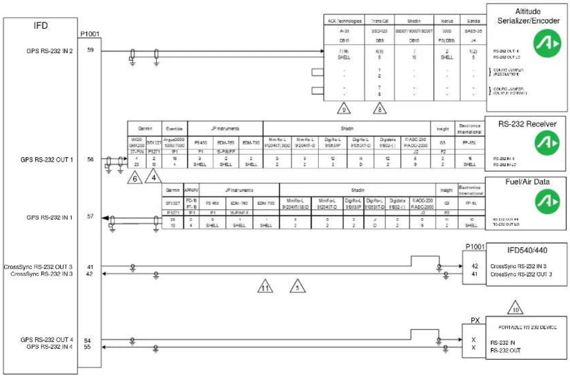
flowchart
graph TD
    A["GPS RS-232 OUT 1"] --> B["IFD"]
    B --> C["GPS RS-232 IN 2"]
    C --> D["Altitude Serializer/Encoder"]
    D --> E["RS-232 Receiver"]
    E --> F["Fuel/Air Data"]
    F --> G["CrossSync RS-232 OUT 3"]
    G --> H["GPS RS-232 IN 4"]

    subgraph GPS RS-232 OUT 1
        I["1:23"] --> J["2:0"] --> K["3:8"] --> L["4:7"]
    end

    subgraph GPS RS-232 IN 1
        M["5:7"] --> N["6:4"] --> O["7:1"] --> P["8:0"] --> Q["9:1"]
    end

    subgraph CrossSync RS-232 OUT 3
        R["10:13"] --> S["13:4"] --> T["14:1"] --> U["15:0"] --> V["16:0"]
    end

    subgraph CrossSync RS-232 IN 3
        W["10:13"] --> X["13:4"] --> Y["14:1"] --> Z["15:0"] --> AA["16:0"]
    end

    subgraph CrossSync RS-232 OUT 3
        AB["10:13"] --> AC["13:4"] --> AD["14:1"] --> AE["15:0"] --> AF["16:0"]
    end

    subgraph CrossSync RS-232 IN 3
        AG["10:13"] --> AH["13:4"] --> AI["14:1"] --> AJ["15:0"] --> AK["16:0"]
    end

    subgraph CrossSync RS-232 OUT 3
        AL["10:13"] --> AM["13:4"] --> AN["14:1"] --> AO["15:0"] --> AP["16:0"]
    end

    subgraph CrossSync RS-232 IN 3
        AQ["10:13"] --> AR["13:4"] --> AS["14:1"] --> AT["15:0"] --> AU["16:0"]
    end

    subgraph CrossSync RS-232 OUT 3
        AV["10:13"] --> AW["13:4"] --> AX["14:1"] --> AY["15:0"] --> AZ["16:0"]
    end

    subgraph CrossSync RS-232 IN 3
        BA["10:13"] --> BB["13:4"] --> BC["14:1"] --> BD["15:0"] --> BE["16:0"]
    end

    subgraph CrossSync RS-232 OUT 3
        BF["10:13"] --> BG["13:4"] --> BH["14:1"] --> BI["15:0"] --> BJ["16:0"]
    end

    subgraph CrossSync RS-232 IN 3
        BK["10:13"] --> BL["13:4"] --> BM["14:1"] --> BN["15:0"] --> BO["16:0"]
    end

    subgraph CrossSync RS-232 OUT 3
        BP["10:13"] --> BQ["13:4"] --> BR["14:1"] --> BS["15:0"] --> BT["16:0"]
    end

    subgraph CrossSync RS-232 IN 3
        BU["10:13"] --> BV["13:4"] --> BW["14:1"] --> BX["15:0"] --> BY["16:0"]
    end

    subgraph CrossSync RS-232 OUT 3
        BWB["10:13"] --> BWZ["13:4"] --> BWX["14:1"] --> BWY["15:0"]
    end

    subgraph CrossSync RS-232 IN 3
        BXZ["10:13"] --> BXZW["13:4"] --> BXZX["14:1"] --> BXZX["15:0"]
    end

    subgraph CrossSync RS-232 OUT 3
        BXZX["10:13"] --> BXZXZ["X-X-X"]

    subgraph CrossSync RS-232 IN 3
        BXZX["X-X-X"]

    subgraph CrossSync RS-232 OUT 3
        BXZXZ["X-X-X"]

    subgraph CrossSync RS-232 IN 3
        BXZXZX["X-X-X"]

    subgraph CrossSync RS-232 OUT 3
        BXZXZX["X-X-X"]

    subgraph CrossSync RS-232 IN 3
        BXZXZX["X-X-X"]

    subgraph CrossSync RS-232 OUT 3
        BXZXZXX["X-X-X"]

    subgraph CrossSync RS-232 IN 3
        BXZXZXX["X-X-X"]

    subgraph CrossSync RS-232 OUT 3
        BXZXZXX["X-X-X"]

    subgraph CrossSync RS-232 IN 3
        BXZXZXX["X-X-X"]

    subgraph CrossSync RS-232 OUT 3
        BXZXZXX["X-X-X"]

    subgraph CrossSync RS-232 IN 3
        BXZXZXX["X-X-X"],        BXZXZXX["X-X-X"]

    subgraph CrossSync RS-232 OUT 3
        BXZXZXX["X-X-X"]

    subgraph CrossSync RS-232 IN 3
        BXZXZXX["X-X-X"]

    subgraph CrossSync RS-232 OUT 3
        BXZXZXX["X-X-X"]

    subgraph CrossSync RS-232 IN 3
        BXZXZX["X-X-X"]

    subgraph CrossSync RS-232 OUT 3
        BXZXZXX["X-X-X"]

    subgraph CrossSync RS-232 IN 3
        BXZXZXX["X-X-X"]

    subgraph CrossSync RS-232 OUT 3
        BXZXZXX["X-X-X"]

    subgraph CrossSync RS-232 IN 3
        BXZXZXX["X-X-Q"]

    subgraph CrossSync RS-232 OUT 3
        BXZXZXX["X-Q"]

    subgraph CrossSync RS-232 IN 3
        BXZXZXX["X-Q"]

    subgraph CrossSync RS-232 OUT 3
        BXZXZXX["X-Q"]

    subgraph CrossSync RS-232 IN 3
        BXZXZXX["X-Q"]

    subgraph CrossSync RS-232 OUT 3
        BXZXZXX["X-Q"]

    subgraph CrossSync RS-232 IN 3
        BXZXZXX["X-Q"]

    subgraph Cross sync RS-232 OUT 3
        BXZXZXX["X-Q"]

    subgraph Cross sync RS-232 IN 3
        BXZXZXX["X-Q"]

    subgraph Cross sync RS-232 OUT 3
        BXZXZXX["X-Q"]

    subgraph Cross sync RS-232 IN 3
        BXZXZXX["X-Q"]

    subgraph Cross sync RS-232 OUT 3
        BXZXZXX["X-Q"]

    subgraph Cross sync RS-232 IN 4
        BXZXZXX["X-Q"]

    subgraph Cross sync RS-232 OUT 4
        BXZXZXX["X-Q"]

    subgraph Cross sync RS-232 IN 4
        BXZXZXX["X-Q"]

    subgraph Cross sync RS-232 OUT 4
        BXZXZXX["X-Q"]

    subgraph Cross sync RS-232 IN 4
        BXZXZX["X-Q"]

    subgraph Cross sync RS-232 OUT 4
        BXZXZX["X-Q"]

    subgraph Cross sync RS-232 IN 4
        BXZZXZX["X-Q"]

    subgraph Cross sync RS-232 OUT 4
        BXZZXZX["X-Q"]

    subgraph Cross sync RS-232 IN 4
        BXZZXZX["X-Q"]

    end

    A -->|P.99| B
    B -->|P.99| C
    C -->|P.99| D
    D -->|P.99| E
    E -->|P.99| F
    F -->|P.99| G
    G -->|P.99| H
    H -->|P.99| I
    I -->|P.99| J
    J -->|P.99| K
    K -->|P.99| L
    L -->|P.99| M
    M -->|P.99| N
    N -->|P.99| O
    O -->|P.99| P
    P -->|P.99| Q
    Q -->|P.99| R
    R -->|P.99| S
    S -->|P.99| T
    T -->|P.99| U
    U -->|P.99| V
    V -->|P.99| W
    W -->|P.99| X
    X -->|P.99| Y
    Y -->|P.99| Z
    Z -->|P.99| AA
    AA -->|P.99| AB
Figure D - 3: RS-232 Serial Data Interconnect
NOTES:
- ALL WIRES TO BE 22 AWG OR GREATER UNLESS OTHERWISE NOTED.
- AT IFD UNIT, TERMINATE SHIELD GROUNDS TO THE CONNECTOR BACKSHELL OR USE CARD-EDGE CONNECTOR TO TERMINATE SHIELD GROUNDS TO BACK PLATE.
- REFER TO SECTION 7 FOR RS-232 CHANNEL SETTINGS

REFER TO THE GTX 327 TRANSPONDER INSTALLATION MANUAL, 190-00187-02, FOR COMPLETE INFORMATION.

IF TWO OR MORE IFD SERIES UNITS ARE INSTALLED, THE RS-232 LINE ON P1001-41 AND P1001-42 MAY BE CROSS-CONNECTED TO CROSSFILL FLIGHT PLANS AND USER WAYPOINTS. TO CROSSFILL FLIGHT PLANS, IT IS REQUIRED THAT BOTH UNITS HAVE IDENTICAL DATABASE CYCLE DATES AND MAY BE REQUIRED THAT THEY HAVE IDENTICAL VERSIONS OF THE MAIN SOFTWARE. REFERENCE SECTION 4 FOR WIRING INFORMATION.

MAPMX (MAIN SOFTWARE VERSION 3.10 AND LATER) IS THE PREFERRED COMMUNICATION PROTOCOL FOR THE MX20/GMX200. OTHER INPUT PORTS ON MX20/GMX200 MAY BE USED INSTEAD OF THE PORT SHOWN. REFER TO APPROPRIATE MANUFACTURER'S INSTALLATION DOCUMENTATION.
- REFER TO MANUFACTURER'S DOCUMENTATION FOR COMPLETE PINOUT AND INTERCONNECT INFORMATION. PINOUTS OF OTHER MANUFACTURER'S UNITS SHOWN HERE ARE FOR REFERENCE ONLY.

IF USING THE SERIAL PORT SOFTWARE METHOD TO CONFIGURE THE OUTPUT OF THE ENCODER, ENSURE THAT THE "TRIMBLE/GARMIN 9600 BPS" FORMAT IS SELECTED.

MOD LEVEL 8 (OR HIGHER) IS REQUIRED TO SUPPORT RS-232 INTERFACE. ENSURE THAT JUMPERS ARE SET FOR "TRIMBLE/GARMIN 9600 BPS" AND "10 FOOT RESOLUTION."

THE IFD STC DOES NOT PROVIDE INSTALLATION APPROVAL OF ANY PORTABLE ELECTRONIC DEVICES. ADDITIONAL INSTALLATION APPROVAL IS REQUIRED FOR THESE DEVICES.

IN SINGLE IFD INSTALLATIONS LEAVE P1001-41 AND P1001-42 OPEN THESE PINS MAY ONLY BE USED FOR CROSS SYNC OF TWO IFDS IN A DUAL IFD INSTALLATION.
- IFD4XX SHOWN. IFD5XX AND ATLAS HAVE TWO ADDITIONAL RS-232 PORTS IN AND OUT ON CONNECTOR P1050 PINS 60, 61, 62, AND 63.
Figure D - 3: RS-232 Serial Data Interconnect
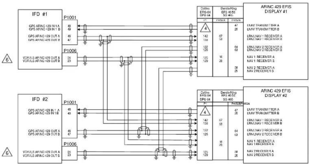
flowchart
graph TD
    subgraph_IFD_1["IFD #1"]
        A1["GPS ARINC 429 IN 1 A"] -->|P1001| B1["48/49"]
        A2["GPS ARINC 429 IN 1 B"] -->|P1001| B2["45/47"]
        A3["GPS ARINC 429 OUT A"] -->|P1001| B3["46/47"]
        A4["GPS ARINC 429 OUT B"] -->|P1001| B4["24/23"]
    end

    subgraph_IFD_2["IFD #2"]
        C1["GPS ARINC 429 IN 1 A"] -->|P1001| D1["48/49"]
        C2["GPS ARINC 429 IN 1 B"] -->|P1001| D2["45/47"]
        C3["GPS ARINC 429 OUT A"] -->|P1001| D3["46/47"]
        C4["GPS ARINC 429 OUT B"] -->|P1001| D4["24/23"]

    end

    subgraph_ARINC_429_EFIS_DISPLAY_1["ARINC 429 EFIS DISPLAY #1"]
        E1["COLINS EFR-64 DPU-64"] --> F1["P1* P1*E*NA P1*E*NB"]
        E2["BendleKing EFS 405C SG 465"] --> F2["P1* P1*E*NA P1*E*NB"]
        E3["LNAV TRANSMITTER A"] --> F3["P1* P1*E*NA P1*E*NB"]
        E4["LNAV TRANSMITTER B"] --> F4["P1* P1*E*NA P1*E*NB"]
        E5["LRMLNAV 1 RECEIVER A"] --> F5["P1* P1*E*NA P1*E*NB"]
        E6["LRMLNAV 1 RECEIVER B"] --> F6["P1* P1*E*NA P1*E*NB"]
        E7["LRMLNAV 2 RECEIVER A"] --> F7["P1* P1*E*NA P1*E*NB"]
        E8["LRMLNAV 2 RECEIVER B"] --> F8["P1* P1*E*NA P1*E*NB"]
        E9["NAV 1 RECEIVER A"] --> F9["P1* P1*E*NA P1*E*NB"]
        E10["NAV 1 RECEIVER B"] --> F10["P1* P1*E*NA P1*E*NB"]
        E11["NAV 2 RECEIVER A"] --> F11["P1* P1*E*NA P1*E*NB"]
        E12["NAV 2 RECEIVER B"] --> F12["P1* P1*E*NA P1*E*NB"]

    end

    subgraph_ARINC_429_EFIS_DISPLAY_2["ARINC 429 EFIS DISPLAY #2"]
        G1["COLINS EFR-64 DPU-64"] --> H1["P1* P1*E*NA P1*E*NB"]
        G2["DendleKing EFS 405C SG 465"] --> H2["P1* P1*E*NA P1*E*NB"]
        G3["LNAV TRANSMITTER A"] --> H3["P1* P1*E*NA P1*E*NB"]
        G4["LNAV TRANSMITTER B"] --> H4["P1* P1*E*NA P1*E*NB"]
        G5["LRMLNAV 1 RECEIVER A"] --> H5["P1* P1*E*NA P1*E*NB"]
        G6["LRMLNAV 1 RECEIVER B"] --> H6["P1* P1*E*NA P1*E*NB"]
        G7["LRMLNAV 2 RECEIVER A"] --> H7["P1* P1*E*NA P1*E*NB"]
        G8["LRMLNAV 2 RECEIVER B"] --> H8["P1* P1*E*NA P1*E*NB"]
        G9["NAV 1 RECEIVER A"] --> H9["P1* P1*E*NA P1*E*NB"]
        G10["NAV 1 RECEIVER B"] --> H10["P1* P1*E*NA P1*E*NB"]
        G11["NAV 2 RECEIVER A"] --> H11["P1* P1*E*NA P1*E*NB"]
        G12["NAV 2 RECEIVER B"] --> H12["P1* P1*E*NA P1*E*NB"]
NOTES:
- ALL WIRES TO BE 24 AWG OR GREATER UNLESS OTHERWISE NOTED.
- AT IFD UNIT, TERMINATE SHIELD GROUNDS TO THE CONNECTOR BACKSHELL OR USE CARD EDGE CONNECTOR TO TERMINATESHIELD GROUNDS TO THE BACKPLATE. THE SHIELD LEADS MUST BE LESS THAN 3.0 INCHES. CONNECT OTHER SHIELD GROUNDS TO AIRCRAFT CHASSIS WITH AS SHORT A CONDUCTOR AS POSSIBLE
-
IF THE GPS ARINC429 IN PORT 1 IS ALREADY USED FOR ANOTHER PURPOSE, THE GPS ARINC429 PORT 2 MAY BE CONNECTED INSTEAD
-
THE DEPICTED COLLINS EFIS-84 INTERFACE DOES NOT SUPPORT SELECTION OF THE GPS COURSE VIA THE EFIS CONTROL PANEL, A GAD42 IS REQUIRED FOR GPS SELECTED CRS
-
REFER TO MANUFACTURER'S DOCUMENTATION FOR COMPLETE PINOUT AND INTERCONNECT INFORMATION. PINOUTS OF OTHER MANUFACTURER'S UNITS SHOWN HERE ARE FOR REFERENCE ONLY
-
NOT APPLICABLE FOR IFD410/510/545, AND ATLAS FMS ONLY UNITS.
Figure D - 4: EFIS Interconnect

flowchart
graph TD
    subgraph_IFD_1["IFD #1"]
        A1["GPS ARINC 429 IN 1 A"] --> P1001["P1001"]
        A2["GPS ARINC 429 IN 1 B"] --> P1001
        A3["GPS ARINC 429 OUT A"] --> P1001
        A4["GPS ARINC 429 OUT B"] --> P1001
        P1001 -->|P1006| R1["ARINC 429 EFIS DISPLAY #1"]
        P1001 -->|P1006| R2["ARINC 429 EFIS DISPLAY #2"]
    end

    subgraph_IFD_2["IFD #2"]
        A5["GPS ARINC 429 IN 1 A"] --> P1001_P1001
        A6["GPS ARINC 429 IN 1 B"] --> P1001_P1001
        A7["GPS ARINC 429 OUT A"] --> P1001_P1001
        A8["GPS ARINC 429 OUT B"] --> P1001_P1001
        P1001 -->|P1006| R3["ARINC 429 EFIS DISPLAY #2"]
        P1001 -->|P1006| R4["ARINC 429 EFIS DISPLAY #2"]
    end

    P1006 -->|P1006| R5["ARINC 429 EFIS DISPLAY #2"]
    P1006 -->|P1006| R6["ARINC 429 EFIS DISPLAY #2"]
    style IFD_1 fill:#f9f,stroke:#333
    style IFD_2 fill:#f9f,stroke:#333
NOTES:
1. ALL WIRES TO BE 22 AWG OR GREATER UNLESS OTHERWISE NOTED.
2. WIRE HARNESS OVERBRAID IS NOT SHOWN BUT MAY BE REQUIRED.
3. REFER TO MANUFACTURER'S DOCUMENTATION FOR COMPLETE PINOUT AND INTERCONNECT INFORMATION.

IF ARINC 429 PORT 1 IS NOT AVAILABLE, USE ANOTHER AVAILABLE PORT.

T APPLICABLE FOR IFD410/510/545, or Atlas FMS Only units
Figure D - 5: Generic EFIS Interconnect

flowchart
graph TD
    subgraph_IFD_1["IFD #1"]
        A1["VOMILE: SWING 428 OUT A, VOR-LS ANG: UO DUTE"] --> B1["P1008"]
        A2["GPS: ARING 428 OUT A, GPS ARING 428 OUT B"] --> B2["P1001"]
        A3["LOGIC: APPROACH"] --> B3["KAIN - TO KAIN + TCOA"]
        A4["KAIN - LEFT KAIN - HOM"] --> B4["KAIN/LO: RAIN - FL/LO KIN/LAT/RFL - FL/LO"]
        A5["KAIN - UP KAIN - FLOW"] --> B5["KAIN VERTICAL - UO"]
        A6["KAIN VERTICAL - FL/LO"] --> B6["KAIN VERTICAL - UO"]
    end

    subgraph_IFD_2["IFD #2"]
        C1["VOMILE: ARING 428 OUT A, VOR-LS ANG: UO DUTE"] --> D1["P1009"]
        C2["GPS: ARING 428 OUT A, GPS ARING 428 OUT B"] --> D2["KAIN - TO KAIN + TCOA"]
        C3["LOGIC: APPROACH"] --> D3["KAIN - UP KAIN - HOM"]
        C4["KAIN - FL/LO KIN/LAT/RFL - FL/LO"]
        C5["KAIN - UP KIN-VETRAL - UO"]
        C6["KAIN VERTICAL - UO"]
    end

    subgraph_AVIPLDT["AVIPLDT 428 EHSI DISPLAY #1"]
        D7["ACRIGRAFT POWER"] --> D8["CONTROL SNNOV"]
        D9["AVIPLDT 428 EHSI DISPLAY #1"] --> D10["AVIPLDT 428 EHSI DISPLAY #1"]
    end

    style IFD_1 fill:#f9f,stroke:#333
    style IFD_2 fill:#f9f,stroke:#333
    style AVIPLDT fill:#ccf,stroke:#333
    style AVIPLDT fill:#cfc,stroke:#333
Figure D - 6: EHSI ARINC 429 Interconnect, Dual IFD5XX/4XX, Sandel SN3308 Interconnect
NOTES:
- ALL WIRES TO BE 24 AWG OR GREATER UNLESS OTHERWISE NOTED.
- AT IFD UNIT, TERMINATE SHIELD GROUNDS TO THE CONNECTOR BACKSHELL OR USE CARD-EDGE CONNECTOR TO TERMINATE SHIELD GROUNDS TO BACK PLATE.
3. IFD #1 SETUP
MAIN ARINC 429 CONFIG: IN 1: LOW, SANDEL EHSI
OUT: LOW, GAMA 429 GRPH W/INT
SDI: LNAV 1
VNAV: DISABLE LABELS WITH SANDEL SW VERSION PRIOR TO 2.3
VNAV: ENABLE LABELS WITH SANDEL SW VERSION 2.3 OR GREATER
VOR/LOC/GS ARINC 429: SDI: VOR/ILS 1
SPEED: RX: LOW SPEED
TX: LOW SPEED
IFD #2 SETUP
MAIN ARINC 429 CONFIG: IN 1: LOW, SANDEL EHSI
OUT: LOW, GAMA 429 GRPH W/INT
SDI: LNAV 2
VNAV: DISABLE LABELS WITH SANDEL SW VERSION PRIOR TO 2.3
VNAV: ENABLE LABELS WITH SANDEL SW VERSION 2.3 OR GREATER
VOR/LOC/GS ARINC 429: SDI: VOR/ILS 2
SPEED: RX: LOW SPEED
TX: LOW SPEED

SANDEL SN3308 #1 AND #2 SETUP ITEMS:
LNAV 1/2 SELECT: IFD540 NAV CHANGE: NAV-1 ENABLE: YES
PORT: 429 PORT-2*
NAV-2 ENABLE: YES
PORT: 429 PORT-2*
ANNUN: SERIAL
COURSE: OBS/LEG
DEVIATION: ANALOG/IN
OBS ROT: NORMAL
OBS CAL: 000.0
RELAY SENSE: NAV-2: P2-33
GPS-1: OFF
GPS-2: OFF
CDI SRC SEL: P2-3
RCVR 1/2: P2-12
"WITH SANDEL SW VERSIONS PRIOR TO VERSION 2.3 NAV 1 /2 MUST BE SET TO "ANALOG" AND ILS MUST BE SET TO "VALID LOW" FOR PROPER OPERATION OF THE VDI. REFER TO SANDEL SIL 3308-8."

THESE PINS ON THE SANDEL SN3308 ARE CONFIGURABLE AND CAN BE CHANGED TO SUIT THE PARTICULAR INSTALLATION.

AUTOPILOT SHOWN FOR REFERENCE ONLY. REFER TO APPROPRIATE AUTOPILOT INTERCONNECT DIAGRAM.
- IF IT IS DESIRED TO USE THE NAV RECEIVERS AS A SOURCE FOR THE SN3308 BEARING POINTERS, IT IS RECOMMENDED THAT THE IFD540/440 #1/#2 COMPOSITE OUTPUTS (P1006-8) BE CONNECTED TO THE SN3308 COMPOSITE INPUTS (P1-29 AND P1-10, #1 AND 2# RESPECTIVELY) AND THE SN3308 BRG NAV-1/NAV-2 BE SET TO "429+COMP".

WITH SANDEL SW VERSIONS PRIOR TO 2.3 ANALOG CONNECTIONS TO THE SN3308 ARE REQUIRED TO ALLOW VERTICAL GUIDANCE TO BE DISPLAYED FOR GPS APPROACHES.

USE RELAY AMERI-KING P/N AK-950-R12-()V OR EQUIVALENT.

USE RELAY LEACH P/N WN460-() () () OR EQUIVALENT.
- REFER TO MANUFACTURER'S DOCUMENTATION FOR COMPLETE PINOUT AND INTERCONNECT INFORMATION.

NOT APPLICABLE FOR IFD410/510/545 or ATLAS FMS ONLY UNITS
Figure D - 7: EHSI ARINC 429 Interconnect, Dual IFD5XX/4XX, Sandel SN3308 Interconnect

flowchart
graph TD
    A["IFD"] -->|GPS ARINC 429 IN 1A GPS ARINC 429 IN 1B| B["P1001"]
    B --> C["Shadin"]
    C --> D["B&D"]
    D --> E["Bensix/King"]
    E --> F["AIR DATA COMPUTER"]
    F --> G["TRANSMITTER A TRANSMITTER B"]

    H["IFD"] -->|GPS ARINC 429 IN 1A GPS ARINC 429 IN 1B| I["P1001"]
    I --> J["Bendix/King Collins"]
    J --> K["Honeywell"]
    K --> L["Laserel"]
    L --> M["User"]
    M --> N["Lilon"]
    N --> O["IRU/AHRS"]
    O --> P["IRU/AHRS TRANSMITTER A IRU/AHRS TRANSMITTER B"]

    Q["IFD"] --> R["GPS RS 232 OUT 1 GPS RS-232 IN 1"]
    R --> S["P1001"]
    S --> T["Insight"]
    T --> U["Sanda"]
    U --> V["TAS 1000"]
    V --> W["SAC 7.55"]
    W --> X["DSUB-25 PLUG"]
    X --> Y["J100"]
    Y --> Z["23"]
    Z --> AA["25"]
    AA --> AB["10"]
    AB --> AC["13"]
    AC --> AD["AIR DATA COMPUTER"]
Figure D - 8: ARINC 429/RS-232 Air Data/IRU/AHRS Interconnect
NOTES:
- ALL WIRES TO BE 22 AWG OR GREATER UNLESS OTHERWISE NOTED.
- AT IFD UNIT, TERMINATE SHIELD GROUNDS TO THE CONNECTOR BACKSHELL OR USE CARD-EDGE CONNECTOR TO TERMINATE SHIELD GROUNDS TO BACK PLATE. THE SHIELD LEADS MUST BE LESS THAN 3.0 INCHES. CONNECT OTHER SHIELD GROUNDS TO AIRCRAFT CHASSIS WITH AS SHORT A CONDUCTOR AS PRACTICAL.

IF THE GPS ARINC 429 IN 1 PORT (P1001-48 AND -49) IS ALREADY USED FOR ANOTHER PURPOSE, THE GPS ARINC 429 IN 2 PORT (P1001-50 AND -51) MAY BE CONNECTED INSTEAD.
- REFER TO SECTION 7 FOR ARINC 429 CHANNEL SETTINGS.
-
REFER TO SECTION 7 FOR RS-232 CHANNEL SETTINGS.
-
REFER TO MANUFACTURER'S DOCUMENTATION FOR COMPELTE PINOUT AND INTERCONNECT INFORMATION. PINOUTS OF OTHER UNITS SHOWN FOR REFERENCE ONLY.
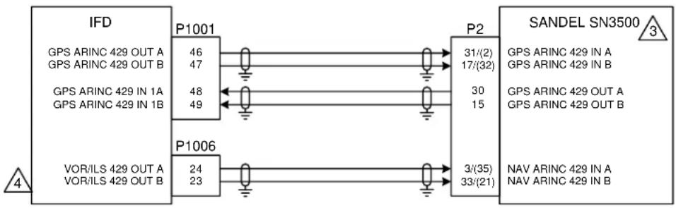
flowchart
graph LR
    A["IFD"] --> B["P1001"]
    A --> C["P1006"]
    B --> D["P2"]
    C --> E["P2"]
    D --> F["SANDEL SN3500"]
    E --> F
    G["GPS ARINC 429 OUT A\nGPS ARINC 429 OUT B\nGPS ARINC 429 IN 1A\nGPS ARINC 429 IN 1B"] --> H["46\n47"]
    I["VOR/ILS 429 OUT A\nVOR/ILS 429 OUT B"] --> J["48\n49"]
    K["GPS ARINC 429 OUT A\nGPS ARINC 429 OUT B\nGPS ARINC 429 OUT A\nGPS ARINC 429 OUT B\n31/(2)\n17/(32)\n30\n15"] --> L["31/(2)\n17/(32)\n30\n15"]
    M["NAV ARINC 429 IN A\nNAV ARINC 429 IN B\n3/(35)\n33/(21)"] --> N["3/(35)\n33/(21)"]
NOTES:
- ALL WIRES TO BE 22 AWG OR GREATER UNLESS OTHERWISE NOTED.
- AT IFD UNIT, TERMINATE SHIELD GROUNDS TO THE CONNECTOR BACKSHELL OR USE CARD-EDGE CONNECTOR TO TERMINATE SHIELD GROUNDS TO BACK PLATE – THE SHIELD LEADS MUST BE LESS THAN 3.0 INCHES. CONNECT OTHER SHIELD GROUNDS TO AIRCRAFT CHASSIS WITH AS SHORT A CONDUCTOR AS PRACTICAL.

REFER TO MANUFACTURER'S DOCUMENTATION FOR COMPLETE PINOUT INFORMATION AND CONFIGURATION.

NOT APPLICABLE FOR IFD410/510/545 OR ATLAS FMS ONLY UNITS
Figure D - 9: Sandel SN3500 Interconnect

flowchart
graph LR
    A["IFD"] -->|13| B["GPS RS-232 OUT 2 (TRAFFIC INTERFACE)"]
    A -->|9| C["P1001"]
    B --> D["58"]
    C --> E["59"]
    D --> F["P1"]
    E --> F
    F --> G["RS-232 RX 2"]
    F --> H["RS-232 TX 2"]
    F --> I["RS-232 GROUND 2"]
    F --> J["REMOTE MUTE"]
    F --> K["TRAFFIC ANNUNCIATE OUT"]
    F --> L["SWITCH"]
    M["OPTIONAL REMOTE MUTE SWITCH"] --> N["5"]
    N --> O["6"]
    P["TO OPTIONAL LAMP OR SONALERT"] --> Q["4"]

flowchart
graph LR
    A["IFD"] -->|9 GPS RS-232 OUT 2 (TRAFFIC INTERFACE)| B["P1001"]
    B -->|58| C["RS-232 16"]
    B -->|59| C
    B -->|56| C
    D["SKYTRAX 6XX TAS6XX-A"] -->|P2 RS-232 RX 2| E["44"]
    D -->|P2 RS-232 TX 2 RS-232 GROUND 2| F["43"]
    D -->|P2 RS-232 RX3| G["46"]
    H["TAWS/EGPWS AUDIO SUPPRESSION OUTPUT"] --> I["15"]
    J["OPTIONAL REMOTE MUTE SWITCH"] --> K["16"]
    L["TO OPTIONAL LAMP OR SONALERT"] --> M["15"]
    N["AUDIO SUPPRESSION IN REMOTE MUTE"] --> O["6"]
    P["TRAFFIC ANNUNCIATE OUT SWITCH"] --> Q["16"]
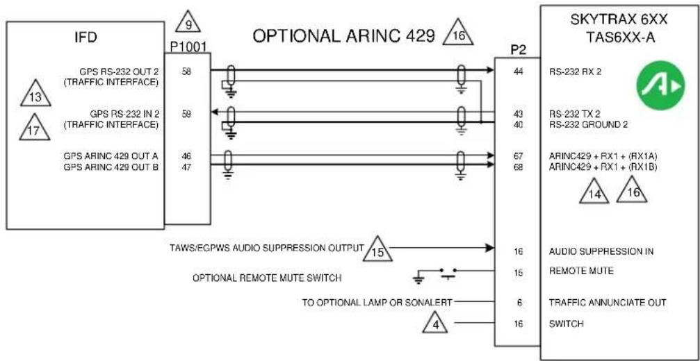
flowchart
graph TD
    A["IFD"] -->|9 GPS RS-232 OUT 2 (TRAFFIC INTERFACE)| B["P1001"]
    A -->|13 GPS RS-232 IN 2 (TRAFFIC INTERFACE)| B
    A -->|17 GPS ARINC 429 OUT A GPS ARINC 429 OUT B| B
    B --> C["P2"]
    C -->|44 RS-232 RX 2| D["SKYTRAX 6XX TAS6XX-A"]
    C -->|43 RS-232 TX 2 | D
    C -->|40 RS-232 GROUND 2| D
    C -->|67 ARINC429 + RX1 + (RX1A) | D
    C -->|68 ARINC429 + RX1 + (RX1B)| D
    D -->|14 AUDIO SUPPRESSION IN | E["SWITCH"]
    D -->|16 REMOTE MUTE | F["TO OPTIONAL LAMP OR SONALERT"]
    D -->|15 AUDIO SUPPRESSION IN | F
    D -->|16 TRAFFIC ANNUNCIATE OUT | F
    D -->|16 AUDIO SUPPRESSION IN | G["TAWS/EGPWS AUDIO SUPPRESSION OUTPUT"]
    D -->|15 TAWS/EGPWS AUDIO SUPPRESSION OUTPUT | H["OPTIONAL REMOTE MUTE SWITCH"]
    H --> I["TO OPTIONAL LAMP OR SONALERT"]
Figure D - 10: Traffic Advisory Interconnect

flowchart
graph TD
    subgraph_IFD_1["IFD"]
        A1["GPS ARINC 429 IN 1A GPS ARINC 429 IN 1B ANNUNCIATE D ANNUNCIATE E"] -->|9| P1001["P1001"]
        A2["GPS ARINC 429 IN 1A GPS ARINC 429 IN 1B ANNUNCIATE D ANNUNCIATE E"] -->|48/49/10/11| P1001
    end
    subgraph_IFD_2["IFD"]
        A3["GPS ARINC 429 IN 1A GPS ARINC 429 IN 1B ANNUNCIATE D ANNUNCIATE E"] -->|9| P1001
        A4["GPS ARINC 429 IN 1A GPS ARINC 429 IN 1B ANNUNCIATE D ANNUNCIATE E"] -->|48/49/10/11| P1001
    end
    subgraph_IFD_3["IFD"]
        A5["GPS ARINC 429 IN 1A GPS ARINC 429 IN 1B ANNUNCIATE D ANNUNCIATE E"] -->|9| P1001
        A6["GPS ARINC 429 IN 1A GPS ARINC 429 IN 1B ANNUNCIATE D ANNUNCIATE E"] -->|48/49/10/11| P1001
    end
    subgraph_IFD_4["IFD"]
        A7["GPS ARINC 429 IN 1A GPS ARINC 429 IN 1B ANNUNCIATE D ANNUNCIATE E"] -->|9| P1001
        A8["GPS ARINC 429 IN 1A GPS ARINC 429 IN 1B ANNUNCIATE D ANNUNCIATE E"] -->|48/49/10/11| P1001
    end
    subgraph_IFD_5["IFD"]
        A9["GPS ARINC 429 IN 2A GPS ARINC 429 IN 2B GPS ARINC 429 OUT A GPS ARINC 429 OUT B ANNUNCIATE E ANNUNCIATE D ANNUNCIATE E"] -->|50/51/46/47| P1001
    end
    subgraph_IFD_6["IFD"]
        A10["GPS ARINC 429 IN 2A GPS ARINC 429 IN 2B GPS ARINC 429 OUT A GPS ARINC 429 OUT B ANNUNCIATE E ANNUNCIATE D ANNUNCIATE E"] -->|11/10| P1001
    end
    subgraph_IFD_7["IFD"]
        A11["GPS ARINC 429 IN 2A GPS ARINC 429 IN 2B GPS ARINC 429 OUT A GPS ARINC 429 OUT B ANNUNCIATE E ANNUNCIATE E"] -->|3| P1001
    end
    subgraph_IFD_8["IFD"]
        A12["GPS ARINC 429 IN 2A GPS ARINC 429 IN 2B GPS ARINC 429 OUT A GPS ARINC 429 OUT B ANNUNCIATE E ANNUNCIATE D ANNUNCIATE E"] -->|3| P1001
    end
    subgraph_IFD_9["IFD"]
        A13["GPS ARINC 429 IN 2A GPS ARINC 429 IN 2B GPS ARINC 429 OUT A GPS ARINC 429 OUT B ANNUNCIATE E ANNUNCIATE D ANNUNCIATE E"] -->|3| P1001
    end
    subgraph_IFD_10["IFD"]
        A11["GPS ARINC 429 IN 2A GPS ARINC 429 IN 2B GPS ARINC 429 OUT A GPS ARINC 429 OUT B ANNUNCIATE E ANNUNCIATE D ANNUNCIATE E"] -->|50/51/46/47| P1001
    end
    subgraph_IFD_11["IFD"]
        A10["GPS ARINC 429 IN 2A GPS ARINC 429 IN 2B GPS ARINC 429 OUT A GPS ARINC 429 OUT B ANNUNCIATE E ANNUNCIATE D ANNUNCIATE E"] -->|50/51/46/47| P1001
    end
    subgraph_IFD_12["IFD"]
        A8["GPS ARINC 429 IN 2A GPS ARINC 429 IN 2B GPS ARINC 429 OUT A GPS ARINC 429 OUT B ANNUNCIATE E ANNUNCIATE D ANNUNCIATE E"] -->|50/51/46/47| P1001
    end
    subgraph_IFD_13["IFD"]
        A7["GPS ARINC 429 IN 2A GPS ARINC 429 IN 2B GPS ARINC 429 OUT A GPS ARINC 429 OUT B ANNUNCIATE E ANNUNCIATE D ANNUNCIATE E"] -->|50/51/46/47| P1001
    end
    subgraph_IFD_14["IFD"]
        A6["GPS ARINC 429 IN 2A GPS ARINC 429 IN 2B GPS ARINC 429 OUT A GPS ARINC 429 OUT B ANNUNCIATE E ANNUNCIATE D ANNUNCIATE E"] -->|50/51/46/47| P1001
    end
    subgraph_IFD_15["IFD"]
        A5["GPS ARINC 429 IN 2A GPS ARINC 429 IN 2B GPS ARINC 429 OUT A GPS ARINC 429 OUT B ANNUNCIATE E ANNUNCIATE D ANNUNCIATE E"] -->|50/51/46/47| P1001
    end
    subgraph_IFD_16["IFD"]
        A3["GPS ARINC 429 IN 2A GPS ARINC 429 IN 2B GPS ARINC 429 OUT A GPS ARINC 429 OUT B ANNUNCIATE E ANNUNCIATE D ANNUNCIATE E"] -->|50/51/46/47| P1001
    end
    subgraph_IFD_17["IFD"]
        A2["GPS ARINC 429 IN 2A GPS ARINC 429 IN 2B GPS ARINC 429 OUT A GPS ARINC 429 OUT B ANNUNCIATE E ANNUNCIATE D ANNUNCIATE E"] -->|50/51/46/47| P1001
    end
    subgraph_IFD_18["IFD"]
        A3["GPS ARINC 429 IN 2A GPS ARINC 429 IN 2B GPS ARINC 429 OUT A GPS ARINC 429 OUT B ANNUNCIATE E ANNUNCIATE D ANNUNCIATE E"] -->|50/51/46/47| P1001
    end
    subgraph_IFD_19["IFD"]
        A5["GPS ARINC 429 IN 2A GPS ARINC 429 IN 2B GPS ARINC 429 OUT A GPS ARINC 429 OUT B ANNUNCIATE E ANNUNCIATE D ANNUNCIATE E"] -->|50/51/46/47| P1001
    end
    subgraph_IFD_20["IFD"]
        A7["GPS ARINC 429 IN 2A GPS ARINC 429 IN 2B GPS ARINC 429 OUT A GPS ARINC 429 OUT B ANNUNCIATE E ANNUNCIATE D ANNUNCIATE E"] -->|50/51/46/47| P8001["P8001"]
    end
    subgraph_IFD_21["IFD"]
        A8["GPS ARINC 429 IN 2A GPS ARINC 429 IN 2B GPS ARINC 429 OUT A GPS ARINC 429 OUT B ANNUNCIATE E ANNUNCIATE D ANNUNCIATE E"] -->|50/51/46/47| P8001
    end
    subgraph_IFD_22["IFD"]
        A9["GPS ARINC 429 IN 2A GPS ARINC 429 IN 2B GPS ARINC 429 OUT A GPS ARINC 429 OUT B ANNUNCIATE E ANNUNCIATE D ANNUNCIATE E"] -->|50/51/46/47| P8001
    end
    subgraph_IFD_23["IFD"]
        A8["GPS ARINC 429 IN 2A GPS ARINC 429 IN 2B GPS ARINC 429 OUT A GPS ARINC 429 OUT B ANNUNCIATE E ANNUNCIATE D ANNUNCIATE E"] -->|50/51/46/47| P8001
    end
    subgraph_IFD_24["IFD"]
        A7["GPS ARINC 429 IN 2A GPS ARINC 429 IN 2B GPS ARINC 429 OUT A GPS ARINC 429 OUT B ANNUNCIATE E ANNUNCIATE D ANNUNCIATE E"] -->|50/51/46/47| P8001
    end
    subgraph_IFD_25["IFD"]
        A6["GPS ARINC 429 IN 2A GPS ARINC 429 IN 2B GPS ARINC 429 OUT A GPS ARINC 429 OUT B ANNUNCIATE E ANNUNCIATE D ANNUNCIATE E"] -->|50/51/46/47| P8001
    end
    subgraph_IFD_26["IFD"]
        A5["GPS ARINC 429 IN 2A GPS ARINC 429 IN 2B GPS ARINC 429 OUT A GPS ARINC 429 OUT B ANNUNCIATE E ANNUNCIATE D ANNUNCIATE E"] -->|50/51/46/47| P8001
    end
    subgraph_IFD_27["IFD"]
        A3["GPS ARINC 429 IN 2A GPS ARINC 429 IN 2B GPS ARINC 429 OUT A GPS ARINC 429 OUT B ANNUNCIATE E ANNUNCIATE D ANNUNCIATE E"] -->|50/51/46/47| P8001
    end
    subgraph_IFD_28["IFD"]
        A5["GPS ARINC 429 IN 2A GPS ARINC 429 IN 2B GPS ARINC 429 OUT A GPS ARINC 429 OUT B ANNUNCIATE E ANNUNCIATE D ANNUNCIATE E"] -->|50/51/46/47| P8001
    end
    subgraph_IFD_33["IFD"]
        A7["GPS ARINC 429 IN 2A GPS ARINC 429 IN 2B GPS ARINC 429 OUT A GPS ARINC 429 OUT B ANNUNCIATE E ANNUNCIATE D ANNUNCIATE E"] -->|50/51/46/47| P8001
    end
Figure D - 110: Traffic Advisory Interconnect
NOTES:
- ALL WIRES TO BE 24 AWG OR GREATER UNLESS OTHERWISE NOTED.

IF THE GPS ARINC 429 IN 1 PORT (P1001-48 AND -49) IS ALREADY USED FOR ANOTHER PURPOSE. THE GPS ARINC 429 IN 2 PORT (P1001-50 AND -51) MAY BE CONNECTED INSTEAD.

THE SKYWATCH POWER SWITCH PINS, SHOWN ON P1, SHOULD BE CONNECTED TOGETHER TO TURN THE PROCESSOR UNIT ON AND DISCONNECTED TO TURN IT OFF. IF A SKYWATCH CONTROL/DISPLAY UNIT IS NOT IN THE INSTALLATION, A DEDICATED SWITCH MAY BE REQUIRED TO TURN THE SKYWATCH PROCESSOR UNIT ON OR OFF.

THE AVIDYNE/RYAN TAS PROCESSOR SWITCH PIN (P1-16 OR P2-54) SHOULD BE GROUNDED TO TURN THE PROCESSOR UNIT ON, AND OPEN TO TURN THIS UNIT OFF. IF A RYAN TCAD DISPLAY UNIT IS NOT IN THE INSTALLATION, A DEDICATED SWITCH MAY BE REQUIRED TO TURN THE TAS PROCESSOR UNIT ON AND OFF.
-
IF ANY OF THESE TRAFFIC SYSTEMS ARE INSTALLED WITHOUT A CONTROL/DISPLAY UNIT, A PLACARD IS REQUIRED NEAR THE IFD UNIT, INDICATING THAT A TRAFFIC ADVISORY SYSTEM IS INSTALLED, AND ITS DATA MAY BE DISPLAYED ON THE IFD5XX UNIT.
-
REFER TO MANUFACTURER'S DOCUMENTATION FOR COMPLETE PINOUT AND INTERCONNECT INFORMATION. PINOUTS OF OTHER INPUTS SHOWN FOR REFERENCE ONLY.

IN ORDER FOR SKYWATCH DATA TO BE DISPLAYED ON THE IFD5XX UNIT'S MAP PAGE, THE IFD5XX UNIT MUST HAVE A DIGITAL HEADING SOURCE, OR THE SKYWATCH MUST HAVE A SYNCHRO OR SERIAL HEADING SOURCE. A STEPPER HEADING SOURCE WILL NOT ALLOW SKYWATCH DATA TO BE DISPLAYED ON THE MAP PAGE.
- AT IFD UNIT, TERMINATE SHIELD GROUNDS TO THE CONNECTOR BACKSHELL OR USE CARDEDGE CONNECTOR SHIELD GROUNDS TO AIRCRAFT CHASSIS WITH AS SHORT A CONDUCTOR AS PRACTICAL.

REFER TO SECTION 7.0 FOR ARINC 429 AND FOR RS-232 SETTINGS. IF AN ARINC 429 TRAFFIC SOURCE IS USED, THE CORRESPONDING ARINC 429 INPUT MUST BE SET TO HIGH SPEED.

KTA 870/KMH 880/KTA 970/KMH 980 SYSTEMS MUST HAVE TRAFFIC CONFIGURED FOR "CONTROLLER TYPE: DISCRETE" AND "DISPLAY VALID: IGNORE".

SKYWATCH MUST BE CONFIGURED FOR AN ARINC 735 TYPE 1 DISPLAY.

FOR GTX 8XX CONFIGURATION SETTINGS, SEE THE GTX 8XX INSTALLATION MANUAL.

IN ORDER FOR AVIDYNE TAS TRAFFIC TO BE DISPLAYED ON THE IFD5XX, A HEADING SOURCE IS REQUIRED.

ACCEPTS ARINC 429 LABELS. INPUTS CAN BE HIGH OR LOW SPREED. NO CONFIGURATION IS REQUIRED

IF AUDIO MUTING IS NECESSARY FOR LOWER-PRIORITY TRAFFIC ANNOUNCEMENTS, THEN USE THE AUDIO SUPPRESSION INPUT TO MUTE TAS. THE LINE IS PULLED LOW TO MUTE THE TAS. IF TAWS/EGPWS DRIVES OR PULLS THE AUDIO SUPPRESSION OUTPUT HIGH THEN THE OUTPUT MUST BE DIODE ISOLATED.

AVIDYNE TAS-A PROCESSORS ACCEPT GPS POSITION INPUTS ON RS232 OR ARINC 429 (BOTH DEPICTED), ONE INPUT REQUIRED.

CONFIGURE RS232 POSITION OUTPUT TO THE TAS-A, SET OUTPUT TO ADS-B+ (G). CONFIGURE ARINC 429 POSITION OUTPUT TO THE TAS-A, SET OUTPUT TO ARINC 743A
Figure D - 10: Traffic Advisory Interconnect

flowchart
graph TD
    A["IFD #1"] -->|6 GPS ARINC 429 OUT 1A GPS ARINC 429 OUT 1B GPS ARINC 429 IN 1A GPS ARINC 429 IN 1B ANNUNCIATE E| B["P1001"]
    C["IFD #2"] -->|6 GPS ARINC 429 IN 1A GPS ARINC 429 IN 1B ANNUNCIATE E| D["P1001"]
    B -->|46 47 48 49 11| E["P3301"]
    D -->|32 35 30 28 46| F["GARMIN GTX 330(ES)/330D(ES)"]
    E -->|3 3 4| G["TIS CONNECT SELECT"]
NOTES:
- ALL WIRES TO BE 22 AWG OR GREATER UNLESS OTHERWISE NOTED.
- AT IFD UNIT, TERMINATE SHIELD GROUNDS TO THE CONNECTOR BACKSHELL OR USE CARD-EDGE CONNECTOR TO TERMINATE SHIELD GROUNDS TO BACK PLATE. THE SHIELD LEADS MUST BE LESS THAN 3.0 INCHES. CONNECT OTHER SHIELD GROUNDS TO AIRCRAFT CHASSIS WITH AS SHORT A CONDUCTOR AS PRACTICAL.
ARINC 429 IN 1 (P3301-32 AND -35) INPUT ALLOWS AUTOMATED START AND STOP OF FLIGHT TIMER AND PLACES THE TRANSPONDER IN GROUND (GND) MODE UPON LANDING.
IF EXTERNAL STBY SELECT IS CONNECTED IN THIS INSTALLATION USE GTX 330 ARINC 429 OUT 1 A AND 1 B, (PINS 37 AND 34) RATHER THAN ARINC 429 OUT 2 A AND 2 B (PINS 30 AND 28) SHOWN. ALTITUDE DATA WILL NOT BE TRANSMITTED OVER ARINC 429 PORT 2 TO THE IFD5XX/4XX/ATLAS UNIT WHEN EXTERNAL STBY SELECT IS GROUNDED. - WHEN TIS IS USED IN THE AIRCRAFT DO NOT CONNECT ANOTHER TRAFFIC SYSTEM TO THE SAME IFD UNIT.


FD SETUP:
MAIN ARINC 429 CONFIG: IN 1: HIGH, GARMIN GTX 330 OUT: SET TO MATCH INSTALLATION

GTX 330 SETUP:
429 INPUT CHANNEL 1: GPS (SPEED SET TO MATCH IFD #1 OUTPUT) 429 OUTPUT CHANNEL 2: GARMIN W/TIS
Figure D - 12: GTX 330 Interconnect

flowchart
graph TD
    A["IFD"] --> B["P1001"]
    B --> C["54"]
    B --> D["55"]
    E["L3 Communications WX-500"] --> F["8"]
    F --> G["20"]
    G --> H["6"]
    I["Bendix/King KGP 560 GA Enhanced GPWS"] --> J["6"]
    J --> K["P1"]
    K --> L["6"]
    M["GARMIN GDL 69/69A Satellite Data Link"] --> N["3"]
    N --> O["6"]
    P["IFD"] --> Q["P1001"]
    Q --> R["56"]
    R --> S[" "]
    T["IFD"] --> U["P1001"]
    U --> V["59"]
    V --> W["58"]
    X["IFD"] --> Y["P1001"]
    Y --> Z["59"]
    Z --> AA["58"]
    AB["OPTIONAL EXTERNAL CLEAR SWITCH"] --> AC["6"]
    AC --> AD["6"]
    AE["RS-232 OUT 4 GPS RS-232 IN 4"] --> AF["P1001"]
    AF --> AG["54"]
    AH["RS-232 RX"] --> AI["8"]
    AJ["RS-232 TX"] --> AK["20"]
    AL["EXTERNAL CLEAR"] --> AM["6"]
    AN["RS-232 GROUND"] --> AO["5"]
NOTES:
1. ALL WIRES TO BE 22 AWG OR GREATER UNLESS OTHERWISE NOTED.
2. AT IFD UNIT, TERMINATE SHIELD GROUNDS TO THE CONNECTOR BACKSHELL OR USE CARD-EDGE CONNECTOR TO TERMINATE SHIELD GROUNDS TO BACK PLATE. THE SHIELD LEADS MUST BE LESS THAN 3.0 INCHES. CONNECT OTHER SHIELD GROUNDS TO AIRCRAFT CHASSIS WITH AS SHORT A CONDUCTOR AS PRACTICAL.

IN ORDER FOR WX-500 DATA TO BE DISPLAYED ON THE IFD540 UNIT'S MAP PAGE, THE IFD540/440 MUST HAVE A DIGITAL HEADING SOURCE, OR THE WX-500 MUST HAVE A SYNCHRO OR SERIAL HEADING SOURCE. A STEPPER HEADING SOURCE WILL NOT ALLOW WX-500 DATA TO BE DISPLAYED ON THE MAP PAGE.

IF AN RS-232 OUTPUT PORT IS CONFIGURED FOR THE HONEYWELL EGPWS, THE CORRESPONDING RS-232 INPUT OF THE SAME PORT MAY NOT BE USED.

REFER TO SECTION 7.0 FOR RS-232 CHANNEL SETTINGS.

CONNECTION TO RS-232 PORT #2 OF THE IFD5XX/4XX/ATLAS UNIT IS SHOWN. IF PORT #2 IS ALREADY IN USE, ANY OTHER AVAILABLE RS-232 PORT MAY BE USED AS WELL EXCEPT PORT #3.

CONNECTION TO RS-232 PORT #2 OF THE GDL 69/69A MAY BE USED AS WELL.
8. REFER TO MANUFACTURER'S DOCUMENTATION FOR COMPLETE PINOUT AND INTERCONNECT INFORMATION. PINOUT OF OTHER UNITS SHOWN FOR REFERENCE ONLY.
Figure D - 13: Terrain and Weather Interconnect
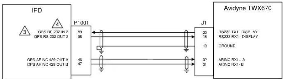
flowchart
graph LR
    A["IFD"] -->|GPS RS-232 IN 2 GPS RS-232 OUT 2 GPS ARINC 429 OUT A GPS ARINC 429 OUT B| B["P1001"]
    B --> C["J1"]
    C --> D["Avidyne TWX670"]
    D -->|RS232 TX1 - DISPLAY RS232 RX1 - DISPLAY GROUND ARINC RX1+ A ARINC RX1-B| E
    B -->|59 58 46 47| F
    C -->|20 18 19 32 31| G

flowchart
graph LR
    A["IFD"] -->|GPS RS-232 IN 2 GPS RS-232 OUT 2| B["P1001"]
    B --> C["Wireless Cable"]
    C --> D["ANDYNE NUE700"]
    D --> E["P1"]
    E --> F["RS-232 OUT 1 RS-232 IN 1 SIGNAL GROUND"]
    style A fill:#f9f,stroke:#333
    style B fill:#ccf,stroke:#333
    style C fill:#cfc,stroke:#333
    style D fill:#fcc,stroke:#333
    style E fill:#cff,stroke:#333
    style F fill:#ffc,stroke:#333
NOTES:
-
ALL WIRES TO BE 22 AWG OR GREATER UNLESS OTHERWISE NOTED.
-
AT IFD UNIT, TERMINATE SHIELD GROUNDS TO THE CONNECTOR BACKSHELL OR USE CARDEDGE CONNECTOR TO TERMINATE SHIELD GROUNDS TO BACK PLATE. THE SHIELD LEADS MUST BE LESS THAN 3.0 INCHES. CONNECT OTHER SHIELD GROUNDS TO AIRCRAFT CHASSIS WITH AS SHORT A CONDUCTOR AS PRACTICAL.

CONNECTION TO RS-232 PORT #2 OF THE IFD540/440 UNIT IS SHOWN. IF PORT #2 IS ALREADY IN USE, ANY OTHER AVAILABLE RS-232 PORT MAY BE USED AS WELL.

REFER TO SECTION 7.0 FOR RS-232 CHANNEL SETTINGS.
- DATA SERVICE FOR MLB700, WSI AV300/350 HAS BEEN DISCONTINUED
Figure D - 14: Weather Interconnect

Figure D - 15: Audio Panel Interconnect
NOTES:
- ALL WIRES TO BE 22 AWG OR GREATER UNLESS OTHERWISE NOTED.

CONNECTING TWO MICROPHONES TO MIC AUDIO HI/LO OR INTERCOM MIC HI/LO AT THE SAME TIME MAY RESULT IN WEAK OR DISTORTED AUDIO. MIC ISOLATION RELAYS ARE RECOMMENDED SO THAT ONLY ONE MIC IS ACTIVE AT A TIME.

IF THE AUDIO PANEL DOES NOT HAVE A LO INPUT. IT SHOULD BE CONNECTED TO A GROUND LUG AT THE AUDIO PANEL.

THE IFD INTERCOM FUNCTION SHOULD ONLY BE USED IF THERE IS NO OTHER INTERCOM SYSTEM IN THE AIRCRAFT.

INTERCOM WIRING OPTION:


THE COM REMOTE TRANSFER INPUT (P1002-15) MAY BE USED FOR EMERGENCY OPERATION OF THE COM TRANSMITTER. IF THE REMOTE TRANSFER SWITCH IS ACTIVE FOR THREE SECONDS, THE ACTIVE COM FREQUENCY WILL CHANGE TO 121.50 MHZ.
-
REFER TO MANUFACTURER'S DOCUMENTATION FOR COMPLETE PINOUT AND INTERCONNECT INFORMATION. PINOUT OF OTHER UNITS SHOWN FOR REFERENCE ONLY.
-
SHIELDS FOR AUDIO CABLES SHOULD BE GROUNDED AT ONE END (WITH LEADS LESS THAN 3.0 INCHES) AND LEFT FLOATING AT THE OTHER END. IF SHIELDED AUDIO CABLE IS CARRIED THROUGH DISCONNECT, CARRY SHIELD GROUND THROUGH DISCONNECT ON SEPARATE PIN.

NOT APPLICABLE FOR IFD 700-00179-X1X, 700-00182-X1X,-X3X
Figure D -15: Audio Panel Interconnect

NOTES:
1. ALL WIRES TO BE 22 AWG OR GREATER UNLESS OTHERWISE NOTED.
2. THIS INTERCONNECT APPLIES ONLY WHEN IT IS DESIRED FOR A SEPARATE INDICATOR TO DISPLAY IFD5XX/4XX/ATLAS VOR/ILS INFORMATION (REGARDLESS OF THE SELECTED NAVIGATION SOURCE).
3. REFER TO MANUFACTURER'S DOCUMENTATION FOR COMPLETE PINOUT AND INTERCONNECT INFORMATION. PINOUTS OF OTHER UNITS SHOWN FOR REFERENCE ONLY.
4. AT IFD UNIT, TERMINATE SHIELD GROUNDS TO THE CONNECTOR BACKSHELL OR USE CARD-EDGE CONNECTOR TO TERMINATE SHIELD GROUNDS TO BACK PLATE - THE SHIELD LEADS MUST BE LESS THAN 3.0 INCHES. CONNECT OTHER SHIELD GROUNDS TO AIRCRAFT CHASSIS WITH AS SHORT A CONDUCTOR AS PRACTICAL.
5. NOT APPLICABLE FOR IFD410/510/545 OR ATLAS FMS ONLY UNITS
Figure D - 16: VOR/ILS Indicator Interconnect

NOTES:
1. ALL WIRES TO BE 22 AWG OR GREATER UNLESS OTHERWISE NOTED.
2. REFER TO MANUFACTURER'S DOCUMENTATION FOR COMPLETE PINOUT AND INTERCONNECT INFORMATION. PINOUTS OF OTHER UNITS SHOWN FOR REFERENCE ONLY.
3. AT IFD UNIT, TERMINATE SHIELD GROUNDS TO THE CONNECTOR BACKSHELL OR USE CARD-EDGE CONNECTOR TO TERMINATE SHIELD GROUNDS TO BACK PLATE - THE SHIELD LEADS MUST BE LESS THAN 3.0 INCHES. CONNECT OTHER SHIELD GROUNDS TO AIRCRAFT CHASSIS WITH AS SHORT A CONDUCTOR AS PRACTICAL.
4. LOWER CASE PIN DESIGNATORS ARE SHOWN AS UNDERLINED LETTERS.
Figure D - 17: Main Indicator Interconnect

NOTES
1. ALL WIRES TO BE 22 AWG OR GREATER UNLESS OTHERWISE NOTED.

TO CONNECT THE IFD TO A KI209A INDICATOR, ADD TWO 10K OHM, % WATT RESISTORS AS SHOWN
3. REFER TO MANUFACTURER'S DOCUMENTATION FOR COMPLETE PINOUT AND INTERCONNECT INFORMATION. PINOUTS OF OTHER UNITS SHOWN FOR REFERENCE ONLY.
4. AT IFD UNIT, TERMINATE SHIELD GROUNDS TO THE CONNECTOR BACKSHIELD OR USE CARD-FIDGF CONNECTOR TO TERMINATE SHIELD GROUNDS TO BACK PLATE - THE SHIELD LEADS MUST BE LESS THAN 3.0 INCHES, CONNECT OTHER SHIELD GROUNDS TO AIRCRAFT CHASSIS WITH AS SHORT A CONDUCTOR AS PRACTICAL.

PROPER CONNECTION OF THE RELAY ENGAGE INPUT OF THE KI 200A IS DEPENDENT ON ITS POWER SUPPLY VOLTAGE. REFER TO KI 200A DOCUMENTATION FOR PROPER CONNECTION.

If the IF DXX-0XX IS INSTALLED, AND ANOTHER VOHLS RECEIVER IS AVAILABLE TO DRIVE THE NAVIGATION INDICATOR. AN EXTERNAL SOURCE SELECTION SWITCH MUST BE USED IN LIFE OF THE GPS ANNUNICATE OUTPUT.
9. For calibration of OBS, first go to the IFD Main Discrete I/O configuration page, and activate the GPS Annunciate output. Then turn to the Main CDI/OBS configuration page to calibrate OBS. Applies to KI208A & KI209A
Figure D - 18 Main Indicator KI209

NOTES:
1. ALL WIRES TO BE 22 AWG OR GREATER UNLESS OTHERWISE NOTED.

TO CONNECT THE IFD TO A KI208A INDICATOR, ADD TWO 10K OHM, ¼ WATT RESISTORS AS SHOWN.
3. REFER TO MANUFACTURER'S DOCUMENTATION FOR COMPLETE PINOUT AND INTERCONNECT INFORMATION. PINOUTS OF OTHER UNITS SHOWN FOR REFERENCE ONLY.
4. AT IFD UNIT, TERMINATE SHIELD GROUNDS TO THE CONNECTOR BACKSHELL OR USE CARD EDGE CONNECTOR TO TERMINATE SHIELD GROUNDS TO BACK PLATE - THE SHIELD LEADS MUST BE LESS THAN 3.0 INCHES. CONNECT OTHER SHIELD GROUNDS TO AIRCRAFT CHASSIS WITH AS SHORT A CONDUCTOR AS PRACTICAL.

PROPER CONNECTION OF THE RELAY ENGAGE INPUT OF THE KI 208A IS DEPENDENT ON ITS POWER SUPPLY VOLTAGE. REFER TO KI 208A DOCUMENTATION FOR PROPER CONNECTION.

IF THE IFD IS INSTALLED, AND ANOTHER VOR/ILS RECEIVER IS AVAILABLE TO DRIVE THE NAVIGATION INDICATOR, AN EXTERNAL SOURCE SELECTION SWITCH MUST BE USED IN LIEU OF THE GPS ANNUNICATE OUTPUT.

NOT APPLICABLE FOR IFD410/510/545 AND ATLAS FMS ONLY UNITS
Figure D - 19: Main Indicator KI208A Interconnect

NOTES:
- ALL WIRES TO BE 22 AWG OR GREATER UNLESS OTHERWISE NOTED.
- THE 200-202/-203/-302/-303 DOES NOT HAVE VERTICAL DEVIATION INDICATOR. DO NOT USE FOR IFR NAVIGATION.
- REFER TO MANUFACTURER'S DOCUMENTATION FOR COMPLETE PINOUT AND INTERCONNECT INFORMATION. PINOUTS OF OTHER UNITS SHOWN FOR REFERENCE ONLY.
- AT IFD UNIT, TERMINATE SHIELD GROUNDS TO THE CONNECTOR BACKSHELL OR USE CARDEDGE CONNECTOR TO TERMINATE SHIELD GROUNDS TO BACK PLATE - THE SHIELD LEADS MUST BE LESS THAN 3.0 INCHES. CONNECT OTHER SHIELD GROUNDS TO AIRCRAFT CHASSIS WITH AS SHORT A CONDUCTOR AS PRACTICAL.

NAVIGATION ANNUNCIATION
Figure D - 20: Main Indicator MD200-20X/-30X Interconnect
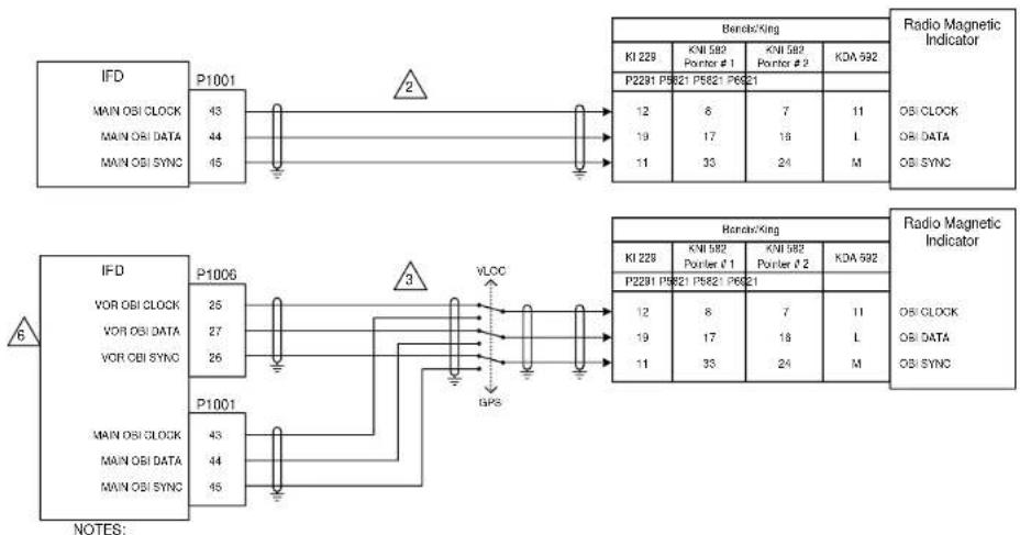
flowchart
graph TD
    A["IFD"] -->|P1001| B["Berech/King"]
    B --> C["KI 229"]
    B --> D["KNI 582"]
    B --> E["KNI 582"]
    B --> F["KOA 592"]
    C --> G["P2291 P5821 P5821 P6621"]
    D --> H["OBI CLOCK"]
    E --> I["ORI DATA"]
    F --> J["OBI SYNC"]
    K["IFD"] -->|P1006| L["Berech/King"]
    L --> M["KI 229"]
    L --> N["KNI 582"]
    L --> O["KNI 582"]
    L --> P["KOA 592"]
    M --> Q["P2291 P5821 P5821 P6621"]
    N --> R["OBI CLOCK"]
    O --> S["ORI DATA"]
    P --> T["OBI SYNC"]
    U["VOR OBI CLOCK"] --> V["P1001"]
    V --> W["GPS"]
    X["VOR OBI DATA"] --> Y["P1001"]
    Z["VOR OBI SYNC"] --> AA["P1001"]
    AB["NOTES:"] --> AC["3"]
    AD["2"] --> AE["43"]
    AF["12"] --> AG["8"]
    AH["7"] --> AI["7"]
    AJ["11"] --> AK["L"]
    AL["19"] --> AM["17"]
    AN["16"] --> AO["L"]
    AP["11"] --> AQ["33"]
    AR["M"] --> AS["24"]
    AT["M"] --> AU["24"]
- ALL WIRES TO BE 22 AWG OR GREATER UNLESS OTHERWISE NOTED.

IF IT IS DESIRED FOR THE RMI POINTER TO SWITCH WITH THE CDI BUTTON ON THE FRONT PANEL OF THE IFD540/440. INSTALL AS PER THE TOP DIAGRAM, AND SELECT TRACK CDI FOR THE OBI SOURCE FIELD OF THE MAIN CDI/OBS CONFIG PAGE.

IT IS DESIRED TO USE A SEPARATE SWITCH FOR THE RMI POINTER, INSTALL AS PER BOTTOM DIAGRAM AND SELECT ALWAYS GPS FOR THE OBI SOURCE FIELD OF THE MAIN CDIOBS CONFIG PAGE.
-
AT IFO UNIT, TERMINATE SHIELD GROUNDS TO THE CONNECTOR BACKSHELL OR USE CARD-EDGE CONNECTOR TO TERMINATE SHIELD GROUNDS TO BACK PLATE - THE SHIELD LEADS MUST BE LESS THAN 3.0 INCHES. CONNECT OTHER SHIELD GROUNDS TO AIRCRAFT CHASSIS WITH AS SHORT A CONDUCTOR AS PRACTICAL.
-
REFER TO MANUFACTURER'S DOCUMENTATION FOR COMPLETE PINOUT AND INTERCONNECT INFORMATION. PINOUTS OF OTHER UNITS SHOWN FOR REFERENCE ONLY.

NOT APPLICABLE FOR IFD410/510/545 OR ATLAS FMS ONLY UNITS
Figure D - 21: RMI/OBI Interconnect
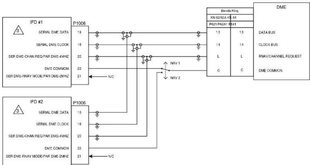
flowchart
graph TD
    subgraph_IFD_1["IFD #1"]
        A["SERIAL DME DATA"] --> B["P1006 19"]
        C["SERIAL DME CLOCK"] --> D["P1006 18"]
        E["SER DME-CHAN REQ/PAR DME-4MHZ"] --> F["P1006 20"]
        G["DME COMMON"] --> H["P1006 22"]
        I["SER DME-RNAV MODE/PAR DME-2MHZ"] --> J["P1006 21"]
    end

    subgraph_IFD_2["IFD #2"]
        K["SERIAL DME DATA"] --> L["P1006 19"]
        M["SERIAL DME CLOCK"] --> N["P1006 18"]
        O["SER DME-CHAN REQ/PAR DME-4MHZ"] --> P["P1006 20"]
        Q["DME COMMON"] --> R["P1006 22"]
        S["SER DME-RNAV MODE/PAR DME-2MHZ"] --> T["P1006 21"]
    end

    subgraph_DME["DMEMED"]
        U["Bendio/King"] --> V["KN 62/82A KO 84"]
        W["P621/F62A1 P641"] --> X["DATA BUS"]
        Y["L"] --> Z["L"]
        AA["C"] --> AB["C"]
    end

    style IFD_1 fill:#f9f,stroke:#333
    style IFD_2 fill:#f9f,stroke:#333
    style DME fill:#ccf,stroke:#333
    style DME_DME fill:#cfc,stroke:#333
NOTES:
1. ALL WIRES TO BE 22 AWG OR GREATER UNLESS OTHERWISE NOTED.
2. AT IFD UNIT, TERMINATE SHIELD GROUNDS TO THE CONNECTOR BACKSHELL OR USE CARD-EDGE
CONNECTOR TO TERMINATE SHIELD GROUNDS TO BACK PLATE - THE SHIELD LEADS MUST BE LESS THAN 3.0 INCHES.
CONNECT OTHER SHIELD GROUNDS TO AIRCRAFT CHASSIS WITH AS SHORT A CONDUCTOR AS PRACTICAL.

THE IFD MUST BE CONFIGURED AT INSTALLATION TO OUTPUT KING SERIAL DME TUNING DATA UNDER THE DME CHANNEL MODE.
4. REFER TO MANUFACTURER'S DOCUMENTATION FOR COMPLETE PINOUT AND INTERCONNECT INFORMATION. PINOUTS OF OTHER UNITS SHOWN FOR REFERENCE ONLY.
5. NOT APPLICABLE FOR IFD410/510/545 OR ATLAS FMS ONLY UNITS
Figure D - 22: King Serial DME Tuning Interconnect, Panel Mount
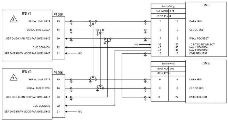
flowchart
graph TD
    subgraph_IFD_1["IFD #1"]
        A["SERIAL DME DATA"] --> B["P1006 19"]
        C["SERIAL DME CLOCK"] --> B
        D["SER DME-CHAN REQ/PAR DME-4MHz"] --> B
        E["DME COMMON"] --> B
        F["SER DME-RNAV MODE/PAR DME-2MHz"] --> B
    end

    subgraph_IFD_2["IFD #2"]
        G["SERIAL DME DATA"] --> H["P1006 19"]
        I["SERIAL DME CLOCK"] --> H
        J["SER DME-CHAN REQ/PAR DME-4MHz"] --> H
        K["DME COMMON"] --> H
        L["SER DME-RNAV MODE/PAR DME-2MHz"] --> H
    end

    B -->|N/C| H
    H -->|N/C| I
    I -->|N/C| J
    J -->|N/C| K
    K -->|N/C| L
    L -->|N/C| M["ANDRX/King"]
    M --> N["KDI 572 KD8 574"]
    M --> O["P5721 P571"]
    N --> P["DATA BUS"]
    O --> Q["CLOCK BUS"]
    P --> R["RNAV REQUEST"]
    Q --> S["10 BIT/50 BIT SELECT"]
    R --> T["NAV 1 COMMON"]
    R --> U["NAV 2 COMMON"]
    R --> V["DME REQUEST"]
    M --> W["DME"]
    W --> X["DATA BUS"]
    W --> Y["CLOCK BUS"]
    W --> Z["DME REQUEST"]
NOTES:
1. ALL WIRES TO BE 22 AWG OR GREATER UNLESS OTHERWISE NOTED.
2. AT IFD UNIT, TERMINATE SHIELD GROUNDS TO THE CONNECTOR BACKSHELL OR USE CARD EDGE CONNECTOR TO TERMINATE SHIELD GROUNDS TO BACK PLATE - THE SHIELD LEADS MUST BE LESS THAN 3.0 INCHES. CONNECT OTHER SHIELD GROUNDS TO AIRCRAFT CHASSIS WITH AS SHORT A CONDUCTOR AS PRACTICAL.

THE IFD MUST BE CONFIGURED AT INSTALLATION TO OUTPUT KING SERIAL DME TUNING DATA UNDER THE DME CHANNEL MODE.
4. REFER TO MANUFACTURER'S DOCUMENTATION FOR COMPLETE PINOUT AND INTERCONNECT INFORMATION. PINOUTS OF OTHER UNITS SHOWN FOR REFERENCE ONLY.
5. NOT APPLICABLE FOR IFD410/510/545 OR ATLAS FMS ONLY UNITS
Figure D - 23: King Serial DME Tuning Interconnect, Remote Mount

NOTES:
- ALL WIRES TO BE 24 AWG OR GREATER UNLESS OTHERWISE NOTED.
2 THE IFD5XX/ATLAS MUST BE CONFIGURED FOR PARALLEL 2X5 DME CHANNELING MODE FOR PROPER OPERATION WITH THIS MODEL OF DME TRANSCEIVER.
3 THE IFD5XX/ATLAS MUST BE CONFIGURED FOR NARCO 890/891 DME CHANNELING MODE FOR PROPER OPERATION WITH THIS MODEL OF DME TRANSCEIVER.
- REFER TO MANUFACTURER'S DOCUMENTATION FOR COMPLETE PINOUT AND INTERCONNECT INFORMATION. PINOUTS OF OTHER UNITS SHOWN FOR REFERENCE ONLY.
5 DME 42 MUST BE STRAPPED FOR 2X5 TUNING. REFER TO DME 42 INSTALLATION MANUAL FOR STRAPPING INFORMATION.
- NOT APPLICABLE FOR IFD410/510/545 OR ATLAS FMS ONLY UNITS
Figure D - 24: Parallel DME Tuning Interconnect
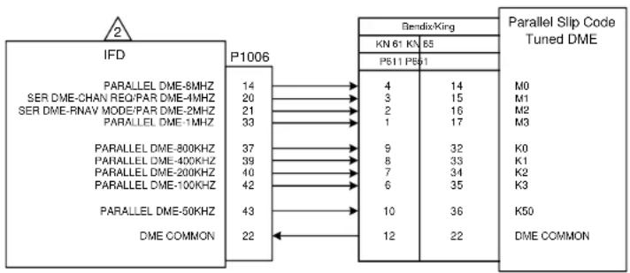
flowchart
graph LR
    A["IFD"] -->|P1006| B["BendsixKing"]
    A -->|P1006| C["Parallel Slip Code Tuned DME"]
    A -->|P1006| D["DME COMMON"]
    B --> E["KN 61 KN 85"]
    B --> F["P511 PS51"]
    C --> G["M0"]
    C --> H["M1"]
    C --> I["M2"]
    C --> J["M3"]
    C --> K["K0"]
    C --> L["K1"]
    C --> M["K2"]
    C --> N["K3"]
    C --> O["K50"]
    C --> P["DME COMMON"]
    A -->|P1006| Q["PARALLEL DME-8MHZ"]
    A -->|P1006| R["PARALLEL DME-4MHZ"]
    A -->|P1006| S["PARALLEL DME-RNAV MODE/PAR DME-2MHZ"]
    A -->|P1006| T["PARALLEL DME-1MHZ"]
    A -->|P1006| U["PARALLEL DME-800KHZ"]
    A -->|P1006| V["PARALLEL DME-400KHZ"]
    A -->|P1006| W["PARALLEL DME-200KHZ"]
    A -->|P1006| X["PARALLEL DME-100KHZ"]
    A -->|P1006| Y["PARALLEL DME-50KHZ"]
    A -->|P1006| Z["DME COMMON"]
    B -->|P1006| AA["4"]
    B -->|P1006| AB["3"]
    B -->|P1006| AC["2"]
    B -->|P1006| AD["1"]
    B -->|P1006| AE["9"]
    B -->|P1006| AF["8"]
    B -->|P1006| AG["7"]
    B -->|P1006| AH["6"]
    B -->|P1006| AI["10"]
    B -->|P1006| AJ["12"]
    B -->|P1006| AK["22"]
NOTES:
- ALL WIRES TO BE 22 AWG OR GREATER UNLESS OTHERWISE NOTED.

THE IFD MUST BE CONFIGURED TO OUTPUT SLIP CODE DME TUNING DATA FOR PROPER OPERATION IN THIS CONFIGURATION.
-
REFER TO MANUFACTURER'S DOCUMENTATION FOR COMPLETE PINOUT AND INTERCONNECT INFORMATION. PINOUTS OF OTHER UNITS SHOWN FOR REFERENCE ONLY.
-
NOT APPLICABLE FOR IFD410/510/545 OR ATLAS FMS ONLY UNITS
Figure D - 25: Parallel DME Tuning Interconnect
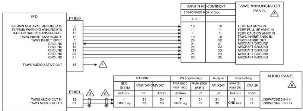
flowchart
graph TD
    A["IFD"] -->|P1050| B["TAWS ANNUNCIATOR PANEL"]
    A -->|P1001| C["TAWS AUDIO OUT HI"]
    A -->|TAWS AUDIO OUT LO| D["TAWS AUDIO OUT HI"]

    B -->|CARM IN MID-CONTINENT| B
    B -->|J1 J1| B
    B -->|10 11 5 19 20 21 22 23 24 25| B
    B -->|10 TERR NA ANNC IN TERR PULL UP ANNC IN TERR CAUTION ANNC IN TAWS INHIBIT ANNC IN TAWS INHIBIT OUT AIRCRAFT GROUND AIRCRAFT GROUND AIRCRAFT GROUND
    B -->|TERR NA ANNC IN TERR PULL UP ANNC IN TERR CAUTION ANNC IN TAWS INHIBIT OUT AIRCRAFT GROUND AIRCRAFT GROUND AIRCRAFT GROUND
    B -->|TERR NA ANNC IN TERR PULL UP ANNC IN TERR CAUTION ANNC IN TAWS INHIBIT OUT AIRCRAFT GROUND AIRCRAFT GROUND AIRCRAFT GROUND
    B -->|TERR NA ANNC IN TERR PULL UP ANNC IN TERR CAUTION ANC IN TAWS INHIBIT OUT AIRCRAFT GROUND AIRCRAFT GROUND AIRCRAFT GROUND
    B -->|TERR NA ANNC IN TERR PULL UP ANNC IN TERR CAUTION ANNC IN TAWS INHIBIT OUT AIRCRAFT GROUND AIRCRAFT GROUND AIRCRAFT GROUND
    B -->|TERR NA ANNC IN TERR PULL UP ANNC IN TERR CAUTION ANNC IN
    B -->|TERR NA ANNC IN TERR PULL UP ANNC IN TERR CAUTION ANNC IN TAWS INHIBIT OUT AIRCRAFT GROUND AIRCRAFT GROUND AIRCRAFT GROUND
    B -->|TERR NA ANNC IN TERR PULL UP ANNC IN TERR CAUTION ANNC IN TAWS INHIBIT OUT AIRCRAFT GROUND AIRCRAFT GROUND AIRCRAFT GROUND
NOTES:
1. ALL WIRES TO BE 22 AWG OR GREATER UNLESS OTHERWISE NOTED.

THE FORWARD LOOKING TERRAIN ALERTING ON THE IFD DOES NOT SATISIFY ANY PART 91/135 REQUIREMENT FOR A TAWS SYSTEM. INSTALLING AN EXTERNAL ANNUNCIATOR IS NOT REQUIRED. TSO'D TAWS-B IS AVAILABLE AS A PAID OPTION FOR IFD 5XX AND ATLAS UNITS WITH SOFTWARE RELEASE 10.3.0.2 OR GREATER. IF FIXED WING TAWS-B IS ENABLED, EXTERNAL ANNUNCIATORS ARE REQUIRED IF THE IFD DOES NOT MEET THE FIELD OF VIEW REQUIREMENTS LISTED IN SECTION 5.1 OF THIS MANUAL

WHEN TWO TAWS-EQUIPPED UNITS ARE INSTALLED IN AN AIRCRAFT, ONLY ONE SHOULD UTILIZE P1001-52/53 TO AVOID COMPETING AUDIO MESSAGES.

CONNECT TO THE AUDIO INHIBIT INPUTS OF OTHER SYSTEMS WITH LOWER PRIORITY AURALS THAN TAWS. THIS CONNECTOR IS NOT AVAILABLE ON THE IFD4XX.

SHIELDS FOR AUDIO CABLES SHOULD BE GROUNDED AT ONE END (WITH LEADS LESS THAN 3.0 INCHES) AND LEFT FLOATING AT THE OTHER END. IF SHIELDED AUDIO CABLE IS CARRIED THROUGH A DISCONNECT, CARRY SHIELD GROUND THROUGHOUT DISCONNECT ON A SEPARATE PIN.

OTHER UNSWITCHED INPUTS ON THE AUDIO PANEL MAY BE USED IN LIEU OF THOSE SHOWN. THESE CONNECTIONS ARE OPTIONAL FOR FLTA, BUT REQUIRED FOR FIXED WING TAWS-B ENABLEMENT
7. REFER TO MANUFACTURER'S DOCUMENTATION FOR COMPLETE PINOUT AND INTERCONNECT INFORMATION. PINOUTS OF OTHER UNITS SHOWN FOR REFERENCE ONLY.
Figure D - 26: TAWS Interconnect

flowchart
graph TD
    A["IFD"] -->|23 24| B["TO MAIN CDI"]
    A -->|21 22| C["MAIN VERTICAL -FLAG"]
    A -->|29 30| D["MAIN VERTICAL -FLAG"]
    A -->|27 28| E["MAIN UP MAIN -DOWN"]
    A -->|46 47| F["GPS ARINC 429 OUT {A B}"]
    A -->|14| G["ILS/GPS APPROACH"]
    H["AUTOPILOT COMPUTER"] --> I["LAT DEV -FLAG"]
    H --> J["LAT DEV -FLAG"]
    H --> K["LAT DEV -LT"]
    H --> L["GS DEV +FLAG"]
    H --> M["GS DEV -FLAG"]
    H --> N["GS DEV +UP"]
    H --> O["GS DEV +DOWN"]
    P["ILS ENEROIZE (A/P)"] --> Q["A} 429 GPS IN"]
    P --> R["B"]
NOTES:
1. ALL WIRES TO BE 22 AWG OR GREATER UNLESS OTHERWISE NOTED.
2. AT IFD UNIT, TERMINATE SHIELD GROUNDS TO THE CONNECTOR BACKSHELL OR USE CARD-EDGE CONNECTOR TO TERMINATE SHIELD GROUNDS TO BACK PLATE - THE SHIELD LEADS MUST BE LESS THAN 3.0 INCHES. CONNECT OTHER SHIELD GROUNDS TO AIRCRAFT CHASSIS WITH AS SHORT A CONDUCTOR AS PRACTICAL.
3. ONLY CONNECTIONS SUPPORTED BY THE AUTOPILOT ARE REQUIRED.

ALL "GAMA 429" CONFIGURATIONS OF THE GPS ARINC 429 OUTPUT PROVIDE DATA REQUIRED BY THE AUTOPILOT FOR GPSS. DO NOT USE ANY OF THE "ARINC 429" CONFIGURATION SELECTIONS.
Figure D - 27: Autopilot Interconnect

NOTES:
1. ALL WIRES TO BE 22 AWG OR GREATER UNLESS OTHERWISE NOTED.
ALL "GAMA 429" CONFIGURATIONS OF THE GPS ARINC 429 OUTPUT PROVIDE DATA REQUIRED BY THE AUTOPILOT FOR GPSS. DO NOT USE ANY OF THE "ARINC 429" CONFIGURATION SELECTIONS.
3. IF AN EFIS SYSTEM IS INSTALLED, NOT ALL OF THE CONNECTIONS SHOWN ARE REQUIRED. SOME OF THESE AUTOPILOT SIGNALS ARE PROVIDED BY THE EFIS SYSTEM. REFER TO MANUFACTURER'S APPROVED DOCUMENTATION FOR DETAILS.
Figure D - 28: Bendix/King Autopilot Interconnect
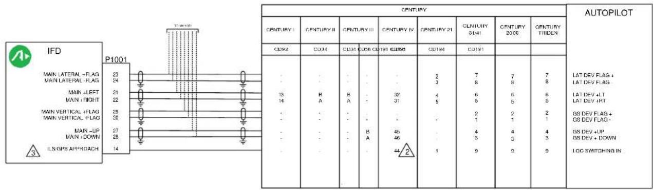
Figure D - 29: Century Autopilot Interconnect Page 1 of 2

flowchart
graph LR
    A["IFD<br>ILSVGPS APPROACH"] --> B["P1001<br>14"]
    B --> C["1N4444<br>OR EQUIV"]
    C --> D["CENTURY IV<br>AUTOPILOT<br>LOC SWITCHING IN"]
    D --> E["CD66<br>44"]
    E --> C
    C --> F["2"]

NOTES:
- ALL WIRES TO BE 22 AWG OR GREATER UNLESS OTHERWISE NOTED.
2 THE CENTURY IV REQUIRES THAT AN ISOLATION DIODE BE INSTALLED ON THE LOC SWITCHING INPUT AS SHOWN.
3 SETUP ITEMS, MAIN SYSTEM CONFIG PAGE: GPS SELECT: AUTO
4 INSTALL JUMPER AS REQUIRED TO SET AK 1081 ARINC 429 INPUT SPEED TO MATCH IFD OUTPUT SETTING. REFER TO MANUFACTURER'S DOCUMENTATION FOR ADDITIONAL DETAILS.
Figure D - 30: Century Autopilot Interconnect Page 2 of 2

other
S-TEC/Coordinant | Component | Value | |---|---| | MAIN LATERAL + FLAG | 23 | | MAIN LATERAL - FLAG | 24 | | MAIN = LEFT | 21 | | MAIN + RIGHT | 22 | | MAIN VERTICAL + FLAG | 29 | | MAIN VERTICAL - FLAG | 30 | | MAIN LUP | 27 | | MAIN + DOWN | 28 | | GPS ARINC 429 OUT A | 48 | | GPS ARINC 429 OUT B | 47 | | GPS ANNUNCIATE | 2 | | ILS/GPS APPROACH | 14 | AUTOPILOT | Component | Value | |---|---| | P1 P1 P1 | - | | P1 P1 P2 P1 P2 | - | | P1 P1 P2 P1 P2 | 0109 0110 | S-TEC/Coordinant | Component | Value | |---|---| | System Twenty | - | | System Thirty | - | | System 40 System 50 | - | | System 55 | - | | System 55X | - | | System 60.1 | - | | System 60 PSS | - | | System 60.2 (2-55) | - | S-TEC/Coordinant | Component | Value | |---|---| | System Twenty | - | | P1 P1 P1 | - | | P1 P1 P2 P1 P2 | - | | P1 P1 P2 P1 P2 | 0109 0110 | S-TEC/Coordinant | Component | Value | |---|---| | System Twenty | - | | System Thirty | - | | System 40 System 50 | - | | System 55 | - | | Systems 55X | - | | Systems 60.1 | - | | Systems 60 PSS | - | | Systems 60.2 (2-55) | - | S-TEC/Coordinant | Component | Value | |---|---| | NAV FLAG + NAV FLAG - | - | | L/R + LT L/R + RT | - | | GS FLAG + GS FLAG - | - | | GS + UP GS + DOWN | - | | GPS STEERING GPS TRACK GAIN LOC SWITCH-425 GPS IN A 425 GPS IN D | - | | GPS SEEDING GPS TRACK GAIN LOC SWITCH-425 GPS IN A 425 GPS IN D | - | | GPS SEEDING GPS TRACK GAIN LOC SWITCH-425 GPS IN A 425 GPS IN D | - | | GPS SEEDING GPS TRACK GAIN LOC SWITCH-425 GPS IN A 425 GPS IN D | - | | GPS SEEDING GPS TRACK GAIN LOC SWITCH-425 GPS IN A 4
flowchart
graph LR
    A["IFD"] --> B["P1001"]
    B --> C["J3"]
    C --> D["S-TEC ST-901 GPSS CONVERTER"]
    D --> E["IFD5XX/4XX/ATLAS"]
    E --> F["J3"]
    F --> G["S-TEC ST-901 GPSS CONVERTER"]

    subgraph SECTECONVERTER
        H["GPS ARINC 429 OUT A\nGPS ARINC 429 OUT B\nVLOG ANNUNCIATE"] --> I["6"]
        J["8"] --> K["9"]
        L["22"] --> M["GPS CHORRIDE"]
    end

    subgraph STEPCONVERTER
        N["GPS ARINC 429 OUT A\nGPS ARINC 429 OUT B\nVLOG ANNUNCIATE"] --> O["46"]
        P["47"] --> Q["47"]
        R["1"] --> S["46"]
        T["1"] --> U["47"]
        V["1"] --> W["46"]
        X["1"] --> Y["47"]
        Z["1"] --> AA["46"]
        AB["1"] --> AC["47"]
        AD["1"] --> AE["46"]
        AF["1"] --> AG["47"]
        AH["1"] --> AI["46"]
        AJ["1"] --> AK["47"]
        AL["1"] --> AM["46"]
        AN["1"] --> AO["47"]
        AP["1"] --> AQ["46"]
        AR["1"] --> AS["47"]
        AT["1"] --> AU["46"]
        AV["1"] --> AW["47"]
        AX["1"] --> AY["46"]
        AZ["1"] --> BA["47"]
        BB["1"] --> BC["46"]
        BD["1"] --> BE["47"]
        BF["1"] --> BG["46"]
        BH["1"] --> BI["47"]
        BJ["1"] --> BK["46"]
        BL["1"] --> BM["47"]
        BN["1"] --> BO["46"]
        BP["1"] --> BQ["47"]
        BR["1"] --> BS["46"]
        BT["1"] --> BU["47"]
        BV["1"] --> BW["46"]
        BX["1"] --> BY["47"]
        BZ["1"] --> CA["46"]
        CB["1"] --> CC["47"]
        DD["1"] --> DE["46"]
        FD["GPS ARINC 429 OUT A\nGPS ARINC 429 OUT B\nVLOG ANNUNCIATE"] --> E
    end
Figure D - 31: S-Tec Autopilot Interconnect Sheet 1 of 2

flowchart
graph LR
    A["IFD"] --> B["P1001"]
    B --> C["(TO OTHER SYSTEM)"]
    B --> D["(AIRCRAFT POWER)"]
    E["S-TEC AUTOPILOT"] --> C
    E --> D
    F["GPS ANNUNCIATE"] --> B
    G["GPS TRACK GAIN"] --> E

flowchart
graph LR
    A["IFD"] --> B["P1001"]
    B --> C["(TO OTHER SYSTEM)"]
    B --> D["(AIRCRAFT POWER)"]
    C --> E["S-TEC AUTOPLOT ST-901 GPSS CONVERTER"]
    D --> E
    E --> F["GPS OVERRIDE"]
    B --> G["VLOC ANNUNICATE"]
NOTES:
- ALL WIRES TO BE 22 AWG OR GREATER UNLESS OTHERWISE NOTED.
- IF THE GPSS UNIT HAS AUTOMATIC LINE SPEED DETECTION THE IFD OUTPUT SHOULD BE SET TO LOW SPEED. REFER TO MANUFACTURER'S DOCUMENTATION FOR DETAILS.
3 FOR CONVERTERS 01278-( ) S/N 600A AND ABOVE.
INSTALL JUMPER AS REQUIRED TO SET AK 1081 ARINC 429 INPUT SPEED TO MATCH IFD OUTPUT SETTING. REFER TO MANUFACTURER'S DOCUMENTATION FOR ADDITIONAL DETAILS.
5 IF THE GPS ANNUNCIATE SIGNAL IS ONLY USED BY THE AUTOPILOT, THIS MAY BE CONNECTED DIRECTLY.
6 IF THE VLOC ANNUNCIATE SIGNAL IS ONLY USED BY THE AUTOPILOT, THIS MAY BE CONNECTED DIRECTLY.
7 FOR CONVERTERS 01278-( ) 599 AND BELOW.
Figure D -31: S-Tec Autopilot Interconnect Sheet 2 of 2
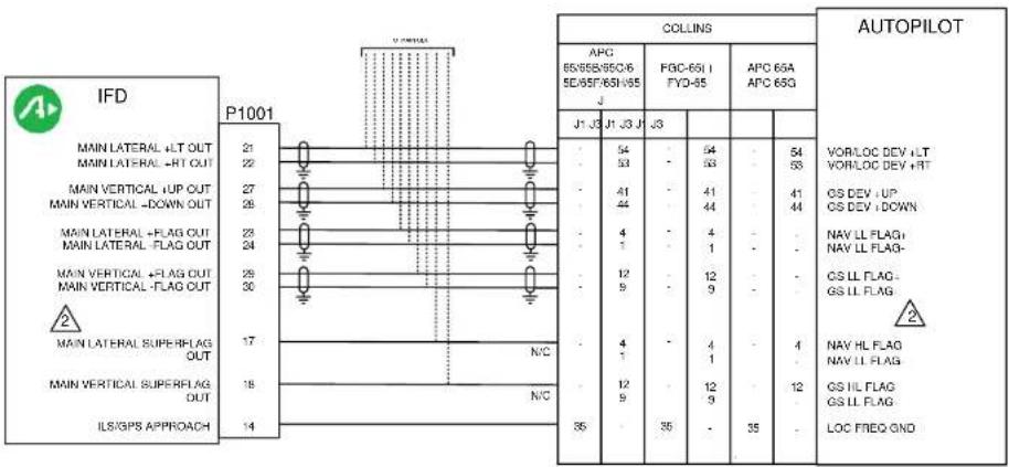
NOTES:
- ALL WIRES TO BE 22 AWG OR GREATER UNLESS OTHERWISE NOTED.

CONNECT EITHER THE LOW-LEVEL FLAGS OR THE SUPERFLAGS. DO NOT CONNECT BOTH SETS OF FLAGS IN A PARTICULAR INSTALLATION
Figure D - 32: Collins Autopilot Interconnect
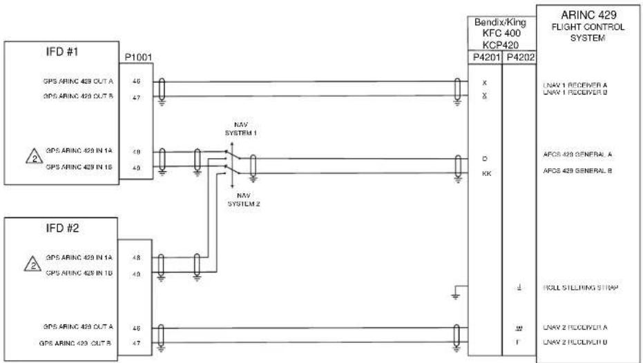
flowchart
graph TD
    subgraph IFD #1
        A["GPS ARINC 429 OUT A"] -->|P1001| B["46"]
        C["GPS ARINC 429 OUT B"] -->|P1001| D["47"]
        E["GPS ARINC 429 IN 1A"] -->|P1001| F["48"]
        G["GPS ARINC 429 IN 1B"] -->|P1001| H["49"]
    end

    subgraph IFD #2
        I["GPS ARINC 429 IN 1A"] -->|P1001| J["48"]
        K["GPS ARINC 429 IN 1B"] -->|P1001| L["49"]
        M["GPS ARINC 429 OUT A"] -->|P1001| N["46"]
        O["GPS ARINC 429 OUT B"] -->|P1001| P["47"]
    end

    subgraph Bendix/King KFC 400 KCP420
        Q["Bendix/King KFC 400 KCP420"] --> R["P4201"]
        S["P4202"] --> T["P4201"]
        U["X"] --> V["D"]
        W["X"] --> X["KK"]
        Y["↓"] --> Z["w"]
        AA["T"] --> AB["↑"]
    end

    subgraph ARINC 429 FLIGHT CONTROL SYSTEM
        AC["ARINC 429 FLIGHT CONTROL SYSTEM"] --> AD["LNAV 1 RECEIVER A"]
        AE["LNAV 1 RECEIVER B"] --> AF["AFOS 429 GENERAL A"]
        AG["AFOS 429 GENERAL B"] --> AH["ACLL STILLING STRAP"]
        AI["LNAV 2 RECOLECTA"] --> AJ["LNAV 2 RECOLECTU"]
    end
NOTES:
1. ALL WIRES TO BE 22 AWG OR GREATER UNLESS OTHERWISE NOTED.
IF THE GPS ARINC 429 IN PORT 1 IS ALREADY BEING USED. GPS ARINC PORT MAY BE USED.
3. LOWER CASE LETTERS SHOWN UNDERLINED.
4. REFER TO MANUFACTURERS' DOCUMENTATION FOR COMPLETE PINOUT AND INTERCONNECT INFORMATION.
Figure D - 33: Bendix King KFC400 Autopilot Interconnect
STACO INDICATOR CONNECTION


flowchart
graph LR
    A["IFD"] --> B["P1001"]
    B --> C["N/C"]
    C --> D["STACO INDICATOR"]
    D --> E["VLOC"]
    D --> F["GPS"]
    D --> G["3"]
    D --> H["6"]
    D --> I["12"]
    E --> J["LAMP VOLTAGE FROM DIMMER CIRCUIT"]
    F --> J
    G --> J
    H --> J
    I --> J
VIVISUN INDICATOR CONNECTION


flowchart
graph LR
    A["IFD"] --> B["P1001"]
    B --> C["VIVISUN INDICATOR"]
    C --> D["P1"]
    D --> E["LAMP VOLTAGE FROM DIMMER CIRCUIT"]
    subgraph P1
        F1["1"] --> G["GPS ANNUNCIATE"]
        H1["2"] --> I["GPS ANNUNCIATE"]
    end
    subgraph VIVISUN
        J1["P1"] --> K["GPS"]
        L1["VLOC"] --> M["GPS"]
        N1["B"] --> O["GPS"]
        P1a["G"] --> Q["A"]
    end
VIVISUN INDICATOR/SWITCH CONNECTION


flowchart
graph LR
    A["IFD"] -->|P1001| B["VIVISUN INDICATOR"]
    C["VLOC ANNUNCIATE"] -->|1| B
    D["GPS ANNUNCIATE"] -->|2| B
    E["CDI SOURCE SELECT"] -->|73| B
    B -->|P1| F["VLOC"]
    B -->|P1| G["GPS"]
    B -->|P1| H["B"]
    B -->|P1| I["G"]
    B -->|P1| J["A"]
    B -->|P1| K["3"]
    L["LAMP VOLTAGE FROM DIMMER CIRCUIT"] --> B
Figure D - 34: External Navigation Source and GPS Annunciators Interconnect Page 1 of 2
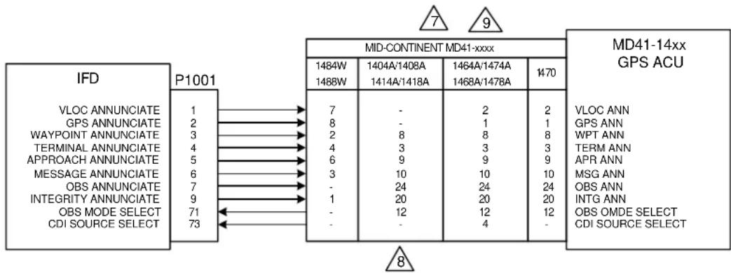
flowchart
graph LR
    A["IFD"] -->|P1001| B["MID-CONTINENT MD41-xxxx"]
    B --> C["MD41-14xx GPS ACU"]
    A -->|VLOC ANNUNCIATE 1| D
    A -->|GPS ANNUNCIATE 2| E
    A -->|WAYPOINT ANNUNCIATE 3| F
    A -->|TERMINAL ANNUNCIATE 4| G
    A -->|APPROACH ANNUNCIATE 5| H
    A -->|MESSAGE ANNUNCIATE 6| I
    A -->|OBS ANNUNCIATE 7| J
    A -->|INTEGRITY ANNUNCIATE 9| K
    A -->|OBS MODE SELECT 71| L
    A -->|CDI SOURCE SELECT 73| M
    B -->|1484W 1488W| N
    B -->|1404A/1408A 1414A/1418A| O
    B -->|1464A/1474A 1468A/1478A| P
    B -->|1470| Q
    B -->|VLOC ANN 7| R
    B -->|GPS ANN 8| S
    B -->|WPT ANN 2| T
    B -->|TERM ANN 4| U
    B -->|APR ANN 6| V
    B -->|MSG ANN 3| W
    B -->|OBS ANN 1| X
    B -->|INTG ANN 1| Y
    B -->|OBS OMDE SELECT 20| Z
    B -->|CDI SOURCE SELECT 12| AA
    B -->|- 24 20 12 4| AB
NOTES:
- ALL WIRES TO BE 24 AWG OR GREATER UNLESS OTHERWISE NOTED.
- IF NAVIAGATION ANNUNCIATORS IS REQUIRED, INDICATORS ON THIS PAGE ARE SUITABLE TO MEET THE ANNUNCIATION REQUIREMENT.
- THE PREFERRED ANNUNCIATION IS VLOC/GPS, ALTHOUGH NAV/GPS WILL BE ACCEPTABLE.
4 STACO SWITCH INDICATOR P/N 992561-1241762200 (14V SYSTEMS) AND P/N 992561-1241862200 (28V SYSTEMS) SHOWN.
5 VIVISUN INDICATOR P/N 95-40-17-B6-AW724 (28V SYSTEMS) SHOWN. INDICATOR MAY BE CONVERTED TO 14V OPERATION BY REPLACING 28V LAMPS WITH 14V LAMPS P/N 14-113.
6 VIVISUN INDICATOR WITH MOMENTARY SWITCH P/N 95-45-11-B6-AW724 (28V SYSTEMS) SHOWN. INDICATOR MAY BE CONVERTED TO 14V OPERATION BY REPLACING 28V LAMPS WITH 14V LAMPS P/N 14-113.
7 THESE UNITS ALSO PROVIDE NAVIGATION SOURCE SELECTION ANNUNCIATION. MID-CONTINENT ANNUNCIATION CONTROL UNITS FOR BOTH 14V AND 28V SYSTEMS SHOWN. THIS DIAGRAM IS PROVIDED TO SHOW INTERCONNECTION BETWEEN IFD540 AND ACU ONLY. REFER TO MID-CONTINENT INSTALLATION MANUAL FOR ADDITIONAL INSTALLATION INFORMATION.
8 CDI SOURCE SELECTION AND ANNUNCIATION IS DONE WITH EXTERNAL RELAYS. REFER TO MID-CONTINENT INSTALLATION MANUAL FOR ADDITIONAL INSTALLATION INFORMATION.
9 5VDC VERSIONS: 146XA(5V) OR 147XA(5V).
- ANNUNCIATOR PART NUMBER 146X HORIZONTAL ORIENTATION. PART NUMBER 147XA ARE VERTICAL ORIENTATION
Figure D -34: External Navigation Source and GPS Annunciators Interconnect

NOTES:
- ALL WIRES TO BE 22 AWG OR GREATER UNLESS OTHERWISE NOTED.

TIME MARK OUT (P1001-16) OUTPUTS A 1 MILISECOND WIDE PULSE ONCE PER SECOND.
- COM REMOTE RECALL (P1001-74) INPUT MAY BE USED TO SCROLL THROUGH A LIST OF PRESET COM FREQUENCIES.
Figure D - 35: Switch Interconnect

flowchart
graph LR
    A["IFD"] --> B["P1001"]
    A --> C["P1006"]
    D["GARMIN GAD 42"] --> E["1"]
    D --> F["2"]
    D --> G["13"]
    D --> H["14"]
    I["VOR/ILS 429 OUT A"] --> J["4"]
    K["VOR/ILS 429 OUT B"] --> L["4"]
    M["P421"] --> N["3"]
    M --> O["4"]
    P["GARMIN GAD 42 3"] --> Q["GPS ARINC 429 IN A"]
    P --> R["GPS ARINC 429 IN B"]
    S["GPS ARINC 429 OUT A"] --> T["GPS ARINC 429 OUT B"]
    U["GPS ARINC 429 IN 1A"] --> V["GPS ARINC 429 IN 1B"]
    W["GPS ARINC 429 OUT B"] --> X["GPS ARINC 429 OUT B"]
    Y["NAV ARINC 429 IN A"] --> Z["NAV ARINC 429 IN B"]
NOTES:
- ALL WIRES TO BE 22 AWG OR GREATER UNLESS OTHERWISE NOTED.
- AT IFD UNIT, TERMINATE SHIELD GROUNDS TO THE CONNECTOR BACKSHELL OR USE CARD-EDGE CONNECTOR TO TERMINATE SHIELD GROUNDS TO BACK PLATE – THE SHIELD LEADS MUST BE LESS THAN 3.0 INCHES. CONNECT OTHER SHIELD GROUNDS TO AIRCRAFT CHASSIS WITH AS SHORT A CONDUCTOR AS PRACTICAL.

SEE GARMIN GAD 42 INSTALLATION MANUAL FOR COMPLETE PIN-OUT AND INTERCONNECTION INFORMATION. GAD42 MUST BE CONFIGURED USING STRAPS ON THE UNIT.

OT APPLICABLE FOR IFD410/510/545 OR ATLAS FMS ONLY UNITS
Figure D - 36: Garmin GAD 42 Interconnect

NOTES:
- ALL WIRES TO BE 22 AWG OR GREATER UNLESS OTHERWISE NOTED.
- AT IFD UNIT, TERMINATE SHIELD GROUNDS TO THE CONNECTOR BACKSHELL OR USE CARD-EDGE CONNECTOR TO TERMINATE SHIELD GROUNDS TO BACK PLATE - THE SHIELD LEADS MUST BE LESS THAN 3.0 INCHES. CONNECT OTHER SHIELD GROUNDS TO AIRCRAFT CHASSIS WITH AS SHORT A CONDUCTOR AS PRACTICAL.
- REFER TO THE MANUFACTURER'S DOCUMENTATION FOR COMPLETE PIN-OUT AND INTERCONNECT INFORMATION. PIN-OUTS OF OTHER UNITS SHOWN FOR REFERENCE ONLY.
- FOR PROPER SETUP TO INTERFACE WITH THE G600. REFER TO THE G600 INSTALLATION MANUAL.
-
FOR OTHER CONNECTION OPTIONS REFER TO THE G600 INSTALLATION MANUAL.
-
NOT APPLICABLE FOR IFD410/510/545 OR ATLAS FMS ONLY UNITS
Figure D - 37: Garmin G600 Interconnect
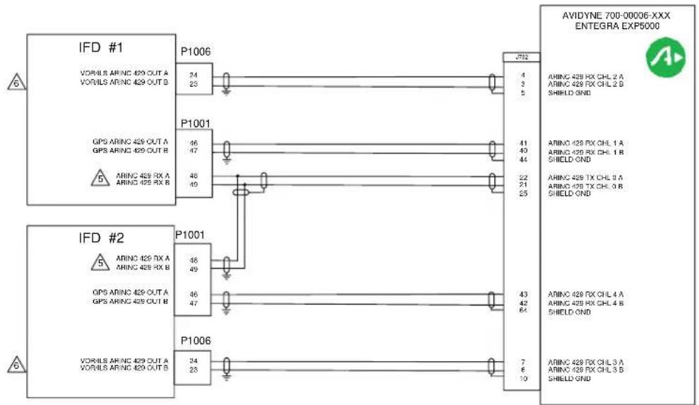
flowchart
graph TD
    A["IFD #1"] --> B["P1006"]
    B --> C["J732"]
    D["IFD #2"] --> E["P1001"]
    E --> F["ARINC 429 RX A\nARINC 429 RX B"]
    G["VORILS ARINC 429 OUT A\nVORILS ARINC 429 OUT B"] --> H["P1001"]
    H --> I["ARINC 429 RX A\nARINC 429 RX B"]
    J["GPS ARINC 429 OUT A\nGPS ARINC 429 OUT B"] --> K["P1001"]
    K --> L["ARINC 429 RX A\nARINC 429 RX B"]
    M["ARINC 429 RX A\nARINC 429 RX B"] --> N["P1006"]
    N --> O["ARINC 429 RX A\nARINC 429 RX B"]
    P["GPS ARINC 429 OUT A\nGPS ARINC 429 OUT B"] --> Q["P1001"]
    Q --> R["ARINC 429 RX A\nARINC 429 RX B"]
    S["VORILS ARINC 429 OUT A\nVORILS ARINC 429 OUT B"] --> T["P1006"]
    T --> U["ARINC 429 RX A\nARINC 429 RX B"]
    V["GPS ARINC 429 OUT A\nGPS ARINC 429 OUT B"] --> W["P1001"]
    W --> X["ARINC 429 RX A\nARINC 429 RX B"]
    Y["GPS ARINC 429 OUT A\nGPS ARINC 429 OUT B"] --> Z["P1006"]
    Z --> AA["ARINC 429 RX A\nARINC 429 RX B"]
    AB["AVIDYNE 700-00006-XXX ENTEGRA EXP5000"] --> AC["J732"]
    AC --> AD["ARINC 429 RX CHL 2 A\nARINC 429 RX CHL 2 B\nSHIELD GND"]
    AC --> AE["ARINC 429 RX CHL 1 A\nARINC 429 RX CHL 1 B\nSHIELD GND"]
    AC --> AF["ARINC 429 TX CHL 8 A\nARINC 429 TX CHL 8 B\nSHIELD GND"]
    AC --> AG["ARINC 429 RX CHL 4 A\nARINC 429 RX CHL 4 B\nSHIELD GND"]
    AC --> AH["ARINC 429 RX CHL 3 A\nARINC 429 RX CHL 3 B\nSHIELD GND"]
NOTES:
-
ALL WIRES TO BE 22 AWG OR GREATER UNLESS OTHERWISE NOTED.
-
AT IFD UNIT, TERMINATE SHIELD GROUNDS TO THE CONNECTOR BACKSHELL OR USE CARD-EDGE CONNECTOR TO TERMINATE SHIELD GROUNDS TO BACK PLATE.
-
WIRE HARNESS OVERBRAID IS NOT SHOWN BUT MAY BE REQUIRED.
-
REFER TO MANUFACTURER'S DOCUMENTATION FOR COMPLETE PINOUT AND INTERCONNECT INFORMATION.
IF THE GPS ARINC 429 IN 1 PORT (P1001-48 AND -49) IS ALREADY USED FOR ANOTHER PURPOSE, THE GPS ARINC 429 IN 2 PORT (P1001-50 AND -51) MAY BE CONNECTED INSTEAD.
6 NOT APPLICABLE FOR IFD410/510/545 OR ATLAS FMS ONLY UNITS
Figure D - 38: Avidyne Entegra Interconnect

flowchart
graph LR
    A["IFD"] --> B["P1001"]
    B --> C["AVIDYNE"]
    C --> D["MFD"]
    subgraph P1001
        E["GPS 428 TX"]
        F["GPS 429 TX"]
    end
    subgraph AVIDYNE
        G["EX500 EX60 EX5000"]
        H["P2 P2 P1"]
        I["5(48) 5(49) 5(49)"]
        J["25(60) 25(61) 25(65)"]
    end
    subgraph MFD
        K["GPS 428 RX"]
        L["GPS 429 RX"]
    end
NOTES:
- ALL WIRES TO BE 22 AWG OR GREATER UNLESS OTHERWISE NOTED.
- AT IFD UNIT, TERMINATE SHIELD GROUNDS TO THE CONNECTOR BACKSHELL OR USE CARD-EDGE CONNECTOR TO TERMINATE SHIELD GROUNDS TO BACK PLATE.
- WIRE HARNESS OVERBRAID IS NOT SHOWN BUT MAY BE REQUIRED.
- REFER TO MANUFACTURER'S DOCUMENTATION FOR COMPLETE PINOUT AND INTERCONNECT INFORMATION.
Figure D - 39: Avidyne EX500/600/5000 Interconnect

flowchart
graph TD
    subgraph_IFD_1["IFD #1"]
        A1["VORILS ARING 429 OUT A"] --> P1006["P1006"]
        B1["VORILS ARING 429 OUT B"] --> P1006
        C1["GPS ARING 429 OUT A"] --> P1001["P1001"]
        D1["GPS ARING 429 OUT B"] --> P1001
        E1["ARINC 429 RX A"] --> P1001
        F1["ARINC 429 RX B"] --> P1001
    end

    subgraph_IFD_2["IFD #2"]
        G1["ARINC 429 RX A"] --> P1001["P1001"]
        H1["ARINC 429 RX B"] --> P1001
        I1["GPS ARING 429 OUT A"] --> P1006["P1006"]
        J1["GPS ARING 429 OUT B"] --> P1006
    end

    subgraph_ASPEN_EFD1000["ASPEN EFD1000"]
        K1["428 VLOC RX2A"] --> P1
        K2["428 VLOC RX2B"] --> P1
        K3["428 GPS RX1A"] --> P1
        K4["428 GPS RX1B"] --> P1
        K5["EFD429 TX1A"] --> P1
        K6["EFD429 TX1B"] --> P1
        K7["428 GPS RX3A"] --> P1
        K8["428 GPS RX3B"] --> P1
        K9["VLOC RX4A"] --> P1
        K10["VLOC RX4B"] --> P1

    end
NOTES:
-
ALL WIRES TO BE 22 AWG OR GREATER UNLESS OTHERWISE NOTED.
-
AT IFD UNIT, TERMINATE SHIELD GROUNDS TO THE CONNECTOR BACKSHELL OR USE CARD-EDGE CONNECTOR TO TERMINATE SHIELD GROUNDS TO BACK PLATE.
-
WIRE HARNESS OVERBRAID IS NOT SHOWN BUT MAY BE REQUIRED.
-
REFER TO MANUFACTURER'S DOCUMENTATION FOR COMPLETE PINOUT AND INTERCONNECT INFORMATION.
5 IF THE GPS ARINC 429 IN 1 PORT (P1001-48 AND -49) IS ALREADY USED FOR ANOTHER PURPOSE, THE GPS ARINC 429 IN 2 PORT (P1001-50 AND -51) MAY BE CONNECTED INSTEAD.
- REFER TO MANUFACTURER'S INSTALL MANUAL FOR AIRDATA CONNECTION. ASPEN EFD1000 S/W 2.X OR LATER WILL TRANSMIT AIRDATA ON THE ARINC 429 TRANSMIT.
NOT APPLICABLE FOR IFD410/510/545 OR ATLAS FMS ONLY UNITS
Figure D - 40: Aspen EFD1000 Interconnect (without ACU)

flowchart
graph TD
    A["IFD #1"] -->|P1006 24 23| B["ASPEN EFD1000"]
    C["IFD #2"] -->|P1001 48 47 48 49| B
    D["VOR/ILS ARINC 429 OUT A VOR/ILS ARINC 429 OUT B"] -->|P1001 48 49 48 47| B
    B -->|19 17| E["429 GPS RX1A 429 GPS RX1B"]
    B -->|20 21| F["428 GPS RX3A 428 GPS RX3B"]
    B -->|22 23| G["428 VLOC RX4A 428 VLOC RX4B"]
    B -->|18 19| H["ACU RX2A ACU TX2S"]
    B -->|26 27| I["428 TX1A 428 TX1B"]
    B -->|F3| J["ASPEN ACU/ACU 2"]
    K["NOTES:"] --> L["428 RX1B 428 RX1A"]
    K --> M["428 TX1B 428 TX1A"]
    K --> N["428 TX2A 428 TX2B"]
    K --> O["428 RX3A 428 RX2B"]
- ALL WIRES TO BE 22 AWG OR GREATER UNLESS OTHERWISE NOTED.
- AT IFD UNIT, TERMINATE SHIELD GROUNDS TO THE CONNECTOR BACKSHELL OR USE CARD-EDGE CONNECTOR TO TERMINATE SHIELD GROUNDS TO BACK PLATE.
- WIRE HARNESS OVERBRAID IS NOT SHOWN BUT MAY BE REQUIRED.
- IF THE GPS ARINC 429 IN 1 PORT (P1001 -48 AND -49) IS ALREADY USED FOR ANOTHER PURPOSE, THE GPS ARINC 429 IN 2 PORT (P1001-50 AND -51) MAY BE CONNECTED INSTEAD.
- THE ACU AND ACU2 TRANSMITS DIFFERENT ARINC 429 LABELS. REFER TO MANUFACTURER'S INSTALL MANUAL FOR DIFFERENCES BETWEEN THE ACU AND ACU2.
6 NOT APPLICABLE FOR IFD410/510/545 OR ATLAS FMS ONLY UNITS
Figure D - 41: Aspen EFD1000 Interconnect (with ACU)
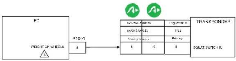
flowchart
graph LR
    A["IFD"] --> B["P1001"]
    B --> C["TRANSPONDER"]
    subgraph P1001
        D["AVYML AVYML"]
        E["AXP46 AVP322"]
        F["Primary Primary"]
        G["5"]
        H["19"]
        I["5"]
    end
    subgraph TRANSPONDER
        J["Trip Avionics"]
        K["TT31"]
        L["Primary"]
        M["5"]
    end
    D --> B
    E --> B
    F --> B
    G --> B
    H --> B
    I --> B
    J --> B
    K --> B
    L --> B
    M --> B
    N["WEIGHT ON WHEELS 4"] --> B
    O["SOLAT SWITCH IN"] --> J
NOTES:
- ALL WIRES TO BE 22 AWG OR GREATER UNLESS OTHERWISE NOTED.
- WIRE HARNESS OVERBRAID IS NOT SHOWN BUT MAY BE REQUIRED.
- REFER TO MANUFACTURER'S DOCUMENTATION FOR COMPLETE PINOUT AND INTERCONNECT INFORMATION.
4 IF THE AIRCRAFT HAS AN EXISTING WEIGHT ON WHEELS OUTPUT, DO NOT CONNECT.

flowchart
graph LR
    A["IFD"] --> B["P1001"]
    B --> C["RS232 OUTPUT 2"]
    B --> D["RS232 INPUT 2"]
    B --> E["5a"]
    B --> F["59"]
    E --> G["3"]
    F --> H["7"]
    I["TRANSPONDER"] --> J["AVIDYNE"]
    I --> K["AVIDYNE"]
    I --> L["AXP340"]
    I --> M["AXP322"]
    I --> N["Secondary"]
    I --> O["25-PIN"]
    J --> P["3"]
    K --> Q["5"]
    L --> R["7"]
    M --> S["25-PIN"]
    N --> T["25-PIN"]
    O --> U["25-PIN"]
    P --> V["RS232 INPUT"]
    Q --> W["RS232 OUTPUT"]
NOTES:
- ALL WIRES TO BE 22 AWG OR GREATER UNLESS OTHERWISE NOTED.
- WIRE HARNESS OVERBRAID IS NOT SHOWN BUT MAY BE REQUIRED.
- REFER TO MANUFACTURER'S DOCUMENTATION FOR COMPLETE PINOUT AND INTERCONNECT INFORMATION
4 IF RS-232 PORT 2 IS NOT AVAILABLE, USE ANY OTHER AVAILABLE PORT EXCEPT RS232 PORT 3, RESERVED FOR CROSS-SYNCH ONLY.
5 ADS-B OUTPUT REQUIRES A SEPARATE INSTALLATION APPROVAL.
Figure D - 42: Transponder Interconnect

flowchart
graph LR
    A["IFD"] --> B["RS232 OUTPUT 2"]
    B --> C["P1001 58"]
    C --> D["ELT"]
    D --> E["GPS RS232 INPUT"]
NOTES:
-
ALL WIRES TO BE 22 AWG OR GREATER UNLESS OTHERWISE NOTED.
-
WIRE HARNESS OVERBRAID IS NOT SHOWN BUT MAY BE REQUIRED.
-
REFER TO MANUFACTURER'S DOCUMENTATION FOR COMPLETE PINOUT AND INTERCONNECT INFORMATION.
4 IF RS-232 PORT 2 IS NOT AVAILABLE, USE ANY OTHER AVAILABLE PORT EXCEPT RS232 PORT 3, RESERVED FOR CROSS-SYNCH ONLY.
Figure D - 43: ELT Interconnect
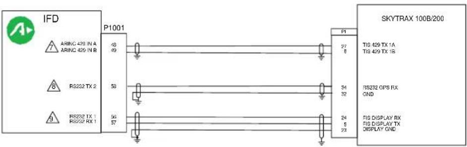
NOTES:
- ALL WIRES TO BE 22 AWG OR GREATER UNLESS OTHERWISE NOTED.
- AT IFD UNIT, TERMINATE SHIELD GROUNDS TO THE CONNECTOR BACKSHELL OR USE CARD EDGE CONNECTOR TO TERMINATE SHIELD GROUNDS TO BACK PLATE.
- WIRE HARNESS OVERBRAID IS NOT SHOWN BUT MAY BE REQUIRED.
- REFER TO MANUFACTURER'S DOCUMENTATION FOR COMPLETE PINOUT AND INTERCONNECT INFORMATION.
- IF RS232 OR ARINC429 PORTS ARE UNAVAILABLE, USE ANY OTHER AVAILABLE PORT EXCEPT RS232 PORT 3, RESERVED FOR CROSS-SYNCH ONLY.
- TRAFFIC DATA IS COMBINED WITH WEATHER OVER RS232 WITH SW VERSION10.2 OR LATER. ARINC 429 CONNECTION IS NOT REQUIRED.
FOR IFD SW VERSION 10.1.1, 10.1.2, OR 10.1.3: CONFIGURE ARINC 429 PORT TOMLB Traffic, Port Speed: High. THIS PORT CAN BE USED IN LATER IFD SW VERSIONS.
8 CONFIGURE GPS RS232 PORT FOR ADS-B+(G)
FOR IFD SW VERSION 10.2 OR LATER; FOR NAVWORX MLB100 CONFIGURE DISPLAY RS232 PORT TO SkyTrax100. FOR SkyTrax 100B/200 CONFIGURE DISPLAY RS232 PORT TO CAPSTONE HS TRFC & WX.
Figure D - 44: MLB100 (NavWorx) and Skytrax100B/200 ADS-B IN Receiver Interconnect

flowchart
Circuit connection diagram showing signal routing between IFD5XX/ATLAS #1 and Bendix/King ART/RDR 2000 Antenna/Receiver Transmitter via P1050 and P5001 transceivers with ARINC 429 and ARINC 453 inputs.NOTES:
- ALL WIRES TO BE 22 AWG MINIMUM UNLESS OTHERWISE SPECIFIED.
- IN DUAL IFD5XX/ATLAS INSTALLATIONS THE RADAR CAN BE CONNECTED TO EITHER IFD. RADAR DATA IS SHARED OVER CROSSSYNC. ONLY IFD5XX/ATLAS MODELS SUPPORTS RADAR DISPLAY AND CONTROL. REQUIRES SW RELEASE 10.2.4.1 OR GREATER.
ARINC 453 DATA BUS: BOTH SHIELDS GROUNDED TO CONNECTOR SHELL AT ART/RDR 2000; OUTER SHIELD GROUNDED ONLY AT IFD5XX UNIT END. WIRE TO BE QUADRAX, NON-PVC JACKET, KPN: 024-00064-0000.
- AT IFD5XX UNIT, TERMINATE SHIELD GROUNDS TO THE CONNECTOR BACKSHELL OR USE CARD-EDGE CONNECTOR TO TERMINATE SHIELD GROUNDS TO BACK PLATE - THE SHIELD LEADS MUST BE LESS THAN 3.0 INCHES. CONNECT OTHER SHIELD GROUNDS TO AIRCRAFT CHASSIS WITH AS SHORT A CONDUCTOR AS PRACTICAL.
- ALL SHIELD GROUND CONNECTIONS SHOWN FOR THE ART/RDR 2000 ARE TO BE CONNECTED TO THE UNIT BACKSHELL GROUND.
- IFD4XX UNITS DO NOT SUPPORT RADAR DISPLAY OR CONTROL.
- SET THE IFD ARINC 429 #2 OUT TO ONBOARD RADAR.
- THESE ARE THE ELECTRICAL CONNECTIONS BETWEEN THE AVIDYNE IFD AND THE BENDIX / KING RDR2000 SYSTEM R/T UNITS. ALL OTHER WIRING IS AT THE DISCRETION OF THE INSTALLER.
Figure D - 45: RDR2000 Interconnect

NOTES:
1. ALL WIRES TO BE 22 AWG MINIMUM UNLESS OTHERWISE SPECIFIED.
2. IN DUAL IFD5XX/ATLAS INSTALLATIONS THE RADAR CAN BE CONNECTED TO EITHER IFD. RADAR DATA IS SHARED OVER CROSSSYNC. ONLY IFD5XX/ATLAS MODELS SUPPORTS RADAR DISPLAY AND CONTROL
3 ARINC 453 DATA BUS: BOTH SHIELDS GROUNDED TO CONNECTOR SHELL AT RS ART; OUTER SHIELD GROUNDED ONLY AT IFD5XX/ATLAS UNIT END.
4. AT IFD5XX/ATLAS UNIT, TERMINATE SHIELD GROUNDS TO THE CONNECTOR BACKSHELL OR USE CARD-EDGE CONNECTOR TO TERMINATE SHIELD GROUNDS TO BACK PLATE - THE SHIELD LEADS MUST BE LESS THAN 3.0 INCHES. CONNECT OTHER SHIELD GROUNDS TO AIRCRAFT CHASSIS WITH AS SHORT A CONDUCTOR AS PRACTICAL.
5. ALL SHIELD GROUND CONNECTIONS SHOWN FOR THE RDS ART ARE TO BE CONNECTED TO THE UNIT BACKSHELL GROUND.
6 SET THE IFD ARINC 429 #2 OUT TO ONBOARD RADAR.
7 SET RADAR CONFIGURATION IN THE IFD/ATLAS AS FOLLOWS (RDS 86P SHOWN):
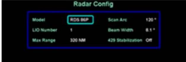
IN DUAL IFD INSTALLATIONS, BOTH IFD UNITS SHALL BE CONFIGURED THE SAME
8. THESE ARE THE ELECTRICAL CONNECTIONS BETWEEN THE AVIDYNE IFD/ATLAS AND THE BENDIX/KING RDS ART UNITS. ALL OTHER WIRING IS AT THE DISCRETION OF THE INSTALLER.
9. REQUIRES IFD SOFTWARE 10.3.0.2 OR LATER
10. SET 'SCAN ARC' ANGLE TO CORRESPOND TO RADAR CAPABILITY
Figure D - 46: RDS Radars Interconnect

NOTES:
- ALL WIRES TO BE 22 AWG MINIMUM UNLESS OTHERWISE SPECIFIED.
- IN DUAL IFD5XX/ATLAS INSTALLATIONS THE RADAR CAN BE CONNECTED TO EITHER IFD. RADAR DATA IS SHARED OVER CROSSSYNC. ONLY IFD 5XX/ATLAS MODELS SUPPORTS RADAR DISPLAY AND CONTROL.
3 ARINC 453 DATA BUS: BOTH SHIELDS GROUNDED TO CONNECTOR SHELL AT ART/RDR; OUTER SHIELD GROUNDED ONLY AT IFD5XX/ATLAS UNIT END. WIRE TO BE QUADRAX, NON-PVC JACKET, KPN: 024-00064-0000.
- AT IFD5XX/ATLAS UNIT, TERMINATE SHIELD GROUNDS TO THE CONNECTOR BACKSHELL OR USE CARD-EDGE CONNECTOR TO TERMINATE SHIELD GROUNDS TO BACK PLATE – THE SHIELD LEADS MUST BE LESS THAN 3.0 INCHES. CONNECT OTHER SHIELD GROUNDS TO AIRCRAFT CHASSIS WITH AS SHORT A CONDUCTOR AS PRACTICAL.
- ALL SHIELD GROUND CONNECTIONS SHOWN FOR THE ART/RDR ARE TO BE CONNECTED TO THE UNIT BACKSHELL GROUND.
6 SET THE IFD ARINC 429 #2 OUT TO ONBOARD RADAR.
7 SET RADAR CONFIGURATION AS FOLLOWS (RDR 2100 SHOWN):
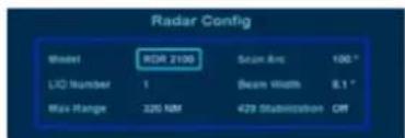
IN DUAL IFD/ATLAS INSTALLATIONS, BOTH UNITS SHALL BE CONFIGURED THE SAME
- THESE ARE THE ELECTRICAL CONNECTIONS BETWEEN THE AVIDYNE IFD/ATLAS AND THE BENDIX / KING RDR2100/2600 SYSTEM R/T UNITS. ALL OTHER WIRING IS AT THE DISCRETION OF THE INSTALLER.
- REQUIRES IFD/ATLAS SOFTWARE RELEASE 10.2.4.1, OR LATER
- SET "SCAN ARC" ANGLE TO CORRESPOND TO RADAR CAPABILITY P/N 071-01550-0101 SCAN ANGLE 90/100/120 P/N 071-01550-0201 SCAN ANGLE 90/100
Figure D - 47: RDR2100/2060 Interconnect
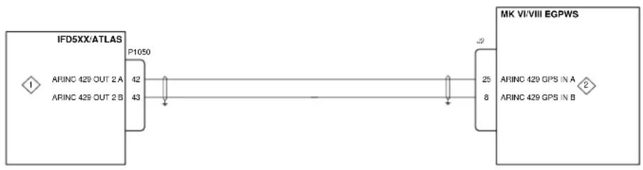
flowchart
graph LR
    A["IFD5XX/ATLAS"] -->|P1050| B["MK VI/VIII EGPWS"]
    A -->|ARINC 429 OUT 2 A| C["IP Address"]
    A -->|ARINC 429 OUT 2 B| D["IP Address"]
    B -->|ARINC 429 GPS IN A| E["IP Address"]
    B -->|ARINC 429 GPS IN B| F["IP Address"]
NOTES:
1 CONFIGURE MAIN ARINC 429 OUT 2 TO "ARINC 743A". SET SPEEDS TO MATCH, EGPWS CONFIG: TYPE 0 FOR LOW SPEED, TYPE 4 FOR HIGH SPEED.
2 IFD GPS ALTITUDE ALTITUDE REFERENCE IS MSL. CONFIGURE EGPWS ALTITUDE REFERENCE TO "MSL".
- COMPATIBLE EGPWS MK VIII PART NUMBERS (W/O INTERNAL GPS) :
965-1206-001 to 965-1206-yyy
965-1210-020 to 965-1210-yyy
- COMPATIBLE EGPWS MK VI PART NUMBERS (W/O INTERNAL GPS):
965-1176-001 to 965-1176-yyy 965-1180-020 to 965-1880-yyy
- IFD FLTA FEATURE MUST BE DISABLED IF INSTALLED IN AIRCRAFT WITH APPROVED TAWS/EGPWS. THIS IS ACCOMPLISHED BY SELECTING "Yes" FOR THE "External TAWS" OPTION IN THE CONFIG TAB OF MAINTENANCE MODE.
Figure D - 48: MK VI and VIII EGPWS Interconnect

flowchart
graph TD
    A["IFD"] --> B["IFD"]
    B --> C["IFD"]
    C --> D["IFD"]
    D --> E["IFD"]
    subgraph IFRS
        F["ARINC 429 OUT 2 A"]
        G["ARINC 429 OUT 2 B"]
    end
    H["IFD"] --> I["P1050"]
    I --> J["P1050"]
    K["IFD"] --> L["P1050"]
    L --> M["P1050"]
    N["IFD"] --> O["P1050"]
    P["IFD"] --> Q["P1050"]
    end
    R["MK V EGPWS"]
    S["MK V-A EGPWS"]
    T["MK VII EGPWS"]
    U["ARINC 429 GPS N/A"]
    V["ARINC 429 GPS N/B"]
NOTES:
1 CONFIGURE IFD MAIN ARINC 429 OUT 2 TO "ARINC 743A" AND SPEED TO CORRESPOND TO EGPWS SPEED SETTING.
2 IFD GPS ALTITUDE ALTITUDE REFERENCE IS MSL. CONFIGURE EGPWS ALTITUDE REFERENCE TO "MSL".
3 CONFIGURE IFD MAIN ARINC 429 OUT 2 TO "ARINC 743A" AND SPEED TO "HIGH".
- COMPATIBLE EGPWS MK V PART NUMBERS (W/O INTERNAL GPS) :
965-0976-003-210-210 to 965-0976-003-yyy-zzz
965-0976-040-210-210 to 965-0976-040-yyy-zzz
- COMPATIBLE EGPWS MK V-A PART NUMBERS:
69000941-101 to 69000941-1xx
- COMPATIBLE EGPWS MK VII PART NUMBERS (W/O INTERNAL GPS):
965-1076-040-210-210 to 965-1076-040-yyy-zzz
- IFD FLTA FEATURE MUST BE DISABLED IF INSTALLED IN AIRCRAFT WITH APPROVED TAWS/EGPWS. THIS IS ACCOMPLISHED BY SELECTING "Yes" FOR THE "External TAWS" OPTION IN THE CONFIG TAB OF MAINTENANCE MODE.
Figure D - 49: MK V, V-A, and VII EGPWS Interconnect
Single IFD Series

flowchart
graph LR
    A["IFD"] --> B["P1001"]
    B --> C["P3251"]
    C --> D["Garmin GTX 335"]
    subgraph GPS RS232 OUT 1
        B1["56"] --> B2["11"]
        B2 --> B3["48"]
        B3 --> B4["49"]
    end
    subgraph DISCRETE OUT
        B1 --> B2
        B2 --> B3
    end
    subgraph ARINC 429 IN 1A
        B1 --> B3
        B3 --> B4
    end
    subgraph ARINC 429 IN 1B
        B1 --> B3
        B3 --> B4
    end
    B1 -->|RS232 IN #2| C
    B1 -->|RS232 GND #2| C
    B2 -->|TIS-A SELECT| C
    B3 -->|ARINC 429 OUT 1A| C
    B3 -->|ARINC 429 OUT 1B| C
    C -->|RS232 IN #2| D
    C -->|RS232 GND #2| D
    C -->|TIS-A SELECT| E
Dual IFD Series

NOTES:
- ALL WIRES TO BE 24 AWG MINIMUM UNLESS OTHERWISE SPECIFIED.
- ALL GROUND CONNECTIONS SHOWN FOR THE GTX335 ARE TO BE CONNECTED TO SHIELD BLOCK GROUND.
- AT IFD UNIT, TERMINATE SHIELD GROUNDS TO THE CONNECTOR BACKSHELL OR USE CARD-EDGE CONNECTOR TO TERMINATE SHIELD GROUNDS TO BACK PLATE - THE SHIELD LEADS MUST BE LESS THAN 3.0 INCHES. CONNECT OTHER SHIELD GROUNDS TO AIRCRAFT CHASSIS WITH AS SHORT A CONDUCTOR AS PRACTICAL.
- IFD SERIAL PORTS (RS232 AND ARINC 429) OTHER THAN THE ONES SHOWN ABOVE MAY BE SUBSTITUTED WITH APPROPRIATE UNIT SOFTWARE CONFIGURATION.
Figure D - 50: GTX 335 Interconnect
Single IFD Series

flowchart
graph TD
    A["IFD"] -->|GPS RS232 OUT 1\nRS232 IN| B["P1001"]
    A -->|ARINC 429 IN 1A\nARINC 429 IN 1B| C["P1050"]
    A -->|TAWS AUDIO\nACTIVE OUT| D["P1001"]
    B -->|P3252\n12| E["Garmin GTX 345\nRS422 B (-)"]
    C -->|P3251\n30\n51\n5\n6\n37| F["AUDIO INHIBIT\n4"]
    B -->|P3252\n12| G["Data Pin P3252"]
    C -->|P3251\n30\n51\n5\n6\n37| H["Data Pin P3251"]
Dual IFD Series
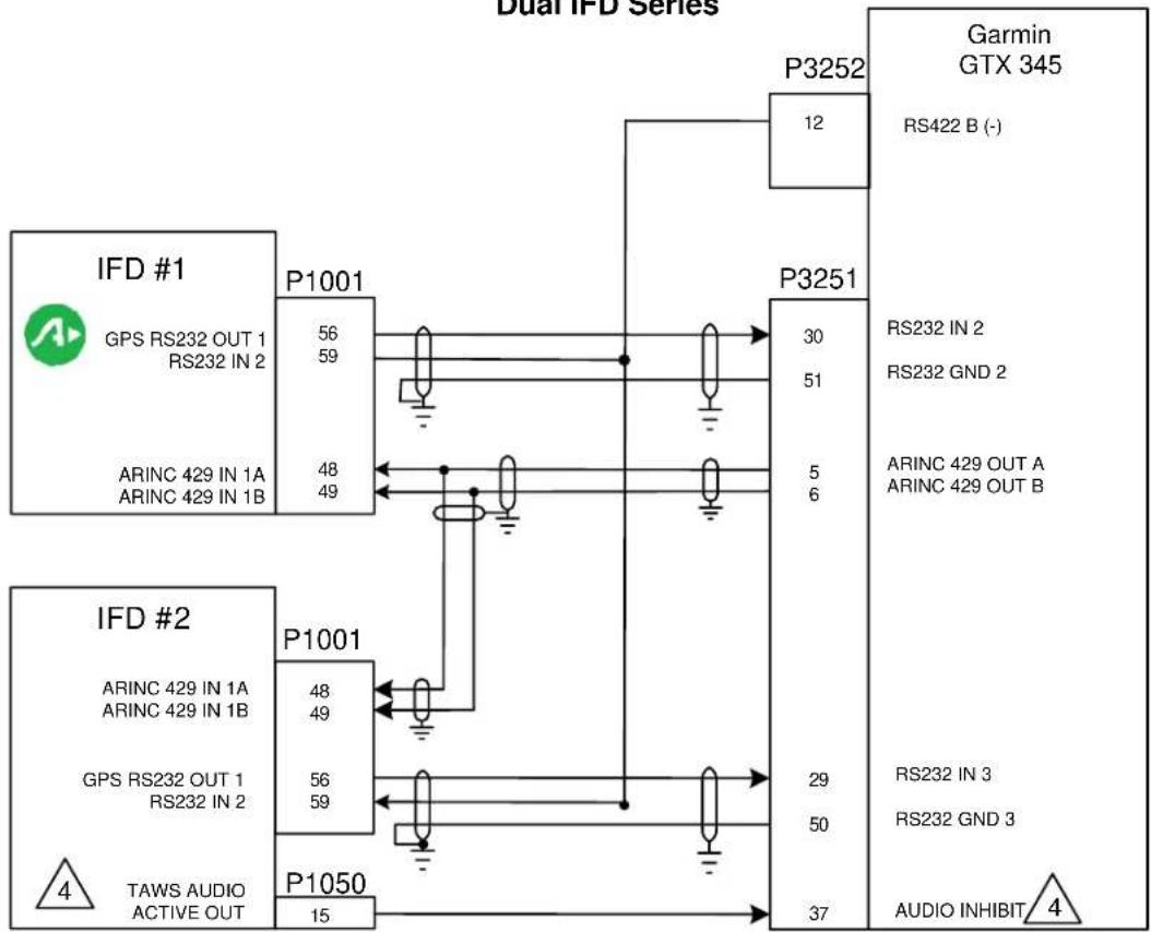
flowchart
graph TD
    A["IFD #1 GPS RS232 OUT 1 RS232 IN 2"] -->|P1001 56 59| B["P3252 12"]
    C["IFD #2 GPS RS232 OUT 1 RS232 IN 2"] -->|P1001 48 49| D["P3251 30"]
    E["TAWS AUDIO ACTIVE OUT"] -->|P1050 15| F["PGS TAWS AUDIO ACTIVE OUT"]
    G["Garmin GTX 345 RS422 B (-)"] -->|P3251 30 51 5 6| H["RS232 IN 2 RS232 GND 2"]
    I["PGS TAWS AUDIO ACTIVE OUT"] -->|P1001 48 49| J["RS232 IN 3 RS232 GND 3"]
    K["ARINC 429 IN 1A ARINC 429 IN 1B"] -->|P1001 48 49| L["RS232 IN 3 RS232 GND 3"]
    M["ARINC 429 IN 1B"] -->|P1001 48 49| N["RS232 IN 3 RS232 GND 3"]
    O["ARINC 429 IN 1A ARINC 429 IN 1B"] -->|P1001 48 49| P["RS232 IN 3 RS232 GND 3"]
    Q["ARINC 429 IN 1B"] -->|P1001 48 49| R["RS232 IN 3 RS232 GND 3"]
    S["ARINC 429 IN 1A ARINC 429 IN 1B"] -->|P1001 48 49| T["RS232 IN 3 RS232 GND 3"]
    U["ARINC 429 IN 1B"] -->|P1001 48 49| V["RS232 IN 3 RS232 GND 3"]
    W["ARINC 429 IN 1A ARINC 429 IN 1B"] -->|P1001 48 49| X["RS232 IN 3 RS232 GND 3"]
    Y["ARINC 429 IN 1B"] -->|P1001 48 49| Z["RS232 IN 3 RS232 GND 3"]
    AA["ARINC 429 IN 1A ARINC 429 IN 1B"] -->|P1001 48 49| AB["RS232 IN 3 RS232 GND 3"]
    AC["ARINC 429 IN 1B"] -->|P1001 48 49| AD["RS232 IN 3 RS232 GND 3"]
    AE["ARINC 429 IN 1A ARINC 429 IN 1B"] -->|P1001 48 49| AF["RS232 IN 3 RS232 GND 3"]
    AG["ARINC 429 IN 1B"] -->|P1001 48 49| AH["RS232 IN 3 RS232 GND 3"]
    AI["ARINC 429 IN 1A ARINC 429 IN 1B"] -->|P1001 48 49| AJ["RS232 IN 3 RS232 GND 3"]
    AK["ARINC 429 IN 1B"] -->|P1001 48 49| AL["RS232 IN 3 RS232 GND 3"]
    AM["ARINC 429 IN 1A ARINC 429 IN 1B"] -->|P1001 48 49| AN["RS232 IN 3 RS232 GND 3"]
    AO["ARINC 429 IN 1B"] -->|P1001 48 49| AP["RS232 IN 3 RS232 GND 3"]
    AQ["ARINC 429 IN 1A ARINC 429 IN 1B"] -->|P1001 48 49| AR["RS232 IN 3 RS232 GND 3"]
    AS["ARINC 429 IN 1A ARINC 429 IN 1B"] -->|P1001 48 49| AT["RS232 IN 3 RS232 GND 3"]
    AU["ARINC 429 IN 1A ARINC 429 IN 1B"] -->|P1001 48 49| AV["RS232 IN 3 RS232 GND 3"]
    AW["ARINC 429 IN 1A ARINC 429 IN 1B"] --> AX["RS232 IN 3 RS232 GND 3"]
    AY["ARINC 429 IN A ARINC 429 IN B"] --> AZ["RS422 B (-)"]
    BA["ARINC 429 IN A ARINC 429 IN B"] --> BB["RS422 B (-)"]
    BC["ARINC 429 IN A ARINC 429 IN B"] --> BD["RS422 B (-)"]
    BE["ARINC 429 IN A ARINC 429 IN B"] --> BF["RS422 B (-)"]
    BG["ARINC 429 IN A ARINC 429 IN B"] --> BH["RS422 B (-)"]
    BI["ARINC 429 IN A ARINC 429 IN B"] --> BJ["RS422 B (-)"]
    BK["ARINC 429 IN A ARINC 429 IN B"] --> BL["RS422 B (-)"]
    BM["ARINC 429 IN A ARINC 429 IN B"] --> BN["RS422 B (-)"]
    BO["ARINC 429 IN A ARINC 429 IN B"] --> BP["RS422 B (-)"]
    BP --> BQ["RS422 B (-)"]
Figure D - 51: GTX 345 Interconnect
NOTES:
-
ALL WIRES TO BE 24 AWG MINIMUM UNLESS OTHERWISE SPECIFIED.
-
ALL GROUND CONNECTIONS SHOWN FOR THE GTX345 ARE TO BE CONNECTED TO SHIELD BLOCK GROUND.
-
AT IFD UNIT, TERMINATE SHIELD GROUNDS TO THE CONNECTOR BACKSHELL OR USE CARD-EDGE CONNECTOR TO TERMINATE SHIELD GROUNDS TO BACK PLATE – THE SHIELD LEADS MUST BE LESS THAN 3.0 INCHES. CONNECT OTHER SHIELD GROUNDS TO AIRCRAFT CHASSIS WITH AS SHORT A CONDUCTOR AS PRACTICAL.

AUDIO INHIBIT MAY BE USED TO INHIBIT GTX-345 TIS-B ALERTS DURING IFD FLTA OR TAWS-B AURAL ANNUNCIATIONS. THIS DOES NOT AFFECT THE APPROVAL OF THE TIS-B FUNCTIONS OF THE GTX 345. GTX345 AUDIO INHIBIT MAY BE DRIVEN BY IFD#1 OR IFD#2 IN DUAL IFDXXX/ATLAS INSTALLATIONS. FD4XX 700-00179-XXX UNITS DO NOT DRIVE AUDIO INHIBIT. IN 700-00179-XXX UNITS SIMULTAINEOUS TIS-B AND FLTA AURAL ANNUNCIATIONS ARE POSSIBLE (ADDRESSED IN AFMS).
- IFD SERIAL PORTS (RS232 AND ARINC 429) OTHER THAN THE ONES SHOWN ABOVE MAY BE SUBSTITUTED WITH APPROPRIATE UNIT SOFTWARE CONFIGURATION.

CONFIGURE SELECTED PORTS WITH THE FOLLOWING SETTINGS:
- If the GTX 345 has an internal GPS receiver, the RS 232 position output connection and configuration setup is not required
• IFD RS232 output setting: ADS-B+ (G2).... GTX 345 RS 232 input setting: ADS-B+ FMT 2
• IFD RS232 input setting: Capstone HS Wx .... GTX 345 RS 422 output setting: Optimized Legacy ADS-B - IFD ARINC429 receive setting: GDL 88 Traffic at High Speed.... GTX 345 ARINC429 transmit setting: Traffic
• Minimum Software Versions Required: IFD v10.2.1 or higher....GTX 345 v2.05 or higher - With software version 10.2.3.1 using the same RS-232 channel for in/out will not accommodate different baud rates. Use different RS-232 ports for in/out with this software version.
Figure D - 51: GTX 345 Interconnect (con't)
Single IFD
to GTX 330 ES

flowchart
graph LR
    A["IFD"] --> B["P1001"]
    B --> C["P3301"]
    C --> D["Garmin GTX 330 ES"]
    A --> E["GPS RS232 OUT 2"]
    A --> F["DISCRETE OUT"]
    A --> G["ARINC 429 IN 1A"]
    A --> H["ARINC 429 IN 1B"]
    A --> I["TAWS/HTAWS AUDIO ACTIVE OUT"]
    J["5"] --> K["P1050"]
    K --> L["15"]
    M["22"] --> N["RS232 IN #1"]
    O["46"] --> P["TIS CONNECT SELECT"]
    Q["30"] --> R["ARINC 429 OUT 2A"]
    S["28"] --> T["ARINC 429 OUT 2B"]
    U["47"] --> V["AUDIO MUTE SELECT"]
Dual IFD to GTX 330 ES

flowchart
graph TD
    subgraph "to GTX 330 ES"
        direction TB
        A["IFD #1"] --> B["P1001"]
        B --> C["P3301"]
        D["IFD #2"] --> E["P1001"]
        E --> F["Garmin GTX 330 ES"]
        G["TAWS/HTAWS AUDIO ACTIVE OUT"] --> H["P1050"]
    end

    subgraph "to GTX 330 ES"
        I["GPS RS232 OUT 2"] --> J["P1001"]
        K["DISCRETE OUT"] --> L["P1001"]
        M["ARINC 429 IN 1A"] --> N["P1001"]
        O["ARINC 429 IN 1B"] --> P["P1001"]
        Q["ARINC 429 IN 1A"] --> R["P1001"]
        S["ARINC 429 IN 1B"] --> T["P1001"]
        U["ARINC 429 IN 1A"] --> V["P1001"]
        W["ARINC 429 IN 1B"] --> X["P1001"]
        Y["ARINC 429 IN 1A"] --> Z["P1001"]
        AA["ARINC 429 IN 1B"] --> AB["P1001"]
        AC["ARINC 429 IN 1A"] --> AD["P1001"]
        AE["ARINC 429 IN 1B"] --> AF["P1001"]
        AG["ARINC 429 IN 1A"] --> AH["P1001"]
        AI["ARINC 429 IN 1B"] --> AJ["P1001"]
        AK["ARINC 429 IN 1A"] --> AL["P1001"]
        AM["ARINC 429 IN 1B"] --> AN["P1001"]
        AO["ARINC 429 IN 1A"] --> AP["P1001"]
        AQ["ARINC 429 IN 1B"] --> AR["P1001"]
        AS["ARINC 429 IN 1A"] --> AT["P1001"]
        AU["ARINC 429 IN 1B"] --> AV["P1001"]
        AW["ARINC 429 IN 1A"] --> AX["P1001"]
        AY["ARINC 429 IN 1B"] --> AZ["P1001"]
        BA["ARINC 429 IN 1A"] --> BB["P1001"]
        BC["ARINC 429 IN 1B"] --> BD["P1001"]
        BE["ARINC 429 IN 1A"] --> BF["P1001"]
        BG["ARINC 429 IN 1B"] --> BH["P1001"]
        BI["ARINC 429 IN 1A"] --> BJ["P1001"]
        BK["ARINC 429 IN 1B"] --> BL["P1001"]
        BM["ARINC 429 IN 1A"] --> BN["P1001"]
        BO["ARINC 429 IN 1B"] --> BP["P1001"]
        BQ["ARINC 429 IN 2A"] --> BR["P3301"]
        BS["ARINC 429 IN 2B"] --> BT["P3301"]
        BU["RS232 IN #2"] --> BV["RS232 GTX 330 ES"]
        BW["RS232 IN #2"] --> BX["RS232 GTX 330 ES"]
        BY["RS232 IN #2"] --> BZ["Audio MUTE SELECT"]
    end

    style "to GTX 330 ES" fill:#f9f,stroke:#333
    style "Garmin GTX 330 ES" fill:#ccf,stroke:#333
NOTES:
- ALL WIRES TO BE 24 AWG MINIMUM UNLESS OTHERWISE SPECIFIED.
- ALL GROUND CONNECTIONS SHOWN FOR THE GTX 330 ES ARE TO BE CONNECTED TO SHIELD BLOCK GROUND.
- AT IFD UNIT, TERMINATE SHIELD GROUNDS TO THE CONNECTOR BACKSHELL OR USE CARD-EDGE CONNECTOR TO TERMINATE SHIELD GROUNDS TO BACK PLATE – THE SHIELD LEADS MUST BE LESS THAN 3.0 INCHES. CONNECT OTHER SHIELD GROUNDS TO AIRCRAFT CHASSIS WITH AS SHORT A CONDUCTOR AS PRACTICAL.
- IFD SERIAL PORTS (RS232 AND ARINC 429) OTHER THAN THE ONES SHOWN ABOVE MAY BE SUBSTITUTED WITH APPROPRIATE UNIT SOFTWARE CONFIGURATION.
5 AUDIO INHIBIT MAY BE USED TO INHIBIT GTX330ES TIS ALERTS DURING IFD4XX/IFD5XX/ATLAS FLTA OR TAWS-B AURAL ANNUNCIATIONS. THIS DOES NOT AFFECT THE APPROVAL OF THE TIS FUNCTIONS OF THE GTX 330ES. AUDIO INHIBIT MAY BE DRIVEN BY IFD#1 OR IFD#2 IN DUAL IFDXXX/ATLAS INSTALLATIONS. IFD4XX 700-00179-XXX UNITS DO NOT DRIVE AUDIO INHIBIT. IN IFD4XX 700-00178-XXX UNITS SIMULTAINEOUS TIS-B AND FLTA AURAL ANNUNCIATIONS ARE POSSIBLE (ADDRESSED IN AFMS).
- GTX 330 MUST BE "ES" ENABLED FOR ADS-B OUT FUNCTIONALITY.
Figure D - 52: GTX 330ES Interconnect

NOTES:

CONFIGURE MAIN ARINC 429 OUT 2 TO "ARINC 743A". SET SPEED TO LOW OR HIGH
Figure D - 53: Garmin GTX 3000 Interconnect

flowchart
graph TD
    A["AXP322 TRANSPONDER"] --> B["25-PIN"]
    B --> C["RS232 OUTPUT 7"]
    B --> D["RS232 INPUT 5"]
    B --> E["SQUAT SWITCH IN 19"]
    B --> F["EXTERNAL STBY 17"]
    B --> G["SUPPRESSION IO 18"]
    B --> H["EXTERNAL IDENT 20"]
    B --> I["AIRCRAFT POWER 15"]
    B --> J["POWER ON 13"]
    B --> K["GROUND 1"]
    B --> L["GROUND 14"]
    B --> M["ANTENNA"]
    C --> N["AVIDYNE DISPLAY"]
    D --> N
    E --> N
    F --> N
    G --> N
    H --> N
    I --> N
    J --> O["MUTUAL SUPPRESSION BUS"]
    K --> P["XDDR 3A 11-33VDC CIRCUIT BREAKER"]
    L --> Q["TO EXISTING ANTENNA"]
    N --> R["RS232 INPUT 59"]
    N --> S["RS232 OUTPUT 58"]
    N --> T["WOW DISerots 8"]
NOTES:
-
ALL WIRES TO BE 22 AWG OR GREATER UNLESS OTHERWISE NOTED.
-
WIRE HARNESS OVERBRAID IS NOT SHOWN BUT MAY BE REQUIRED.
-
REFER TO MANUFACTURER'S DOCUMENTATION FOR COMPLETE PINOUT AND INTERCONNECT INFORMATION.

IF RS-232 PORT 2 IS NOT AVAILABLE, USE ANY OTHER AVAILABLE PORT, USE OF PORT 3 FOR AXP322 SHOULD BE AVOIDED
5. CONFIGURE AXP 322 WOW SELECTION TO AVIDYNE
Figure D - 54: Avidyne AXP322 Interconnect
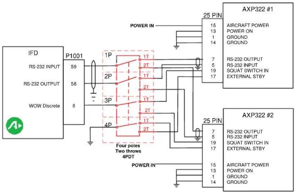
flowchart
graph TD
    A["IFD"] --> B["P1001"]
    C["RS-232 INPUT"] --> D["59"]
    E["RS-232 OUTPUT"] --> F["58"]
    G["WOW Discrete"] --> H["8"]
    I["Power IN"] --> J["1P"]
    K["Power IN"] --> L["2P"]
    M["Power IN"] --> N["3P"]
    O["Power IN"] --> P["4P"]
    Q["AXP322 #1"] --> R["15"]
    Q --> S["13"]
    Q --> T["1"]
    Q --> U["14"]
    V["AIRCRAFT POWER"] --> W["7"]
    V --> X["5"]
    V --> Y["19"]
    V --> Z["17"]
    AA["AIRCRAFT POWER"] --> AB["7"]
    AA --> AC["5"]
    AA --> AD["19"]
    AA --> AE["17"]
    AF["AXP322 #2"] --> AG["15"]
    AF --> AH["13"]
    AF --> AI["1"]
    AF --> AJ["14"]
    AK["AIRCRAFT POWER"] --> AL["15"]
    AK --> AM["13"]
    AK --> AN["1"]
    AK --> AO["14"]
NOTES:
- ALL WIRES TO BE 22 AWG OR GREATER UNLESS OTHERWISE NOTED.
- WIRE HARNESS OVERBRAID IS NOT SHOWN BUT MAY BE REQUIRED.
- REFER TO MANUFACTURER'S DOCUMENTATION FOR COMPLETE PIN-OUT AND INTERCONNECT INFORMATION.
- IF RS-232 PORT 2 IS NOT AVAILABLE, USE ANY OTHER AVAILABLE PORT. USE OF PORT 3 FOR AXP322 SHOULD BE AVOIDED
- EACH TRANSPONDER MUST BE CONFIGURED.
- CONFIGURE AXP322 WOW SELECTION TO AVIDYNE.
Figure D - 55: Avidyne Dual AXP322 Interconnect
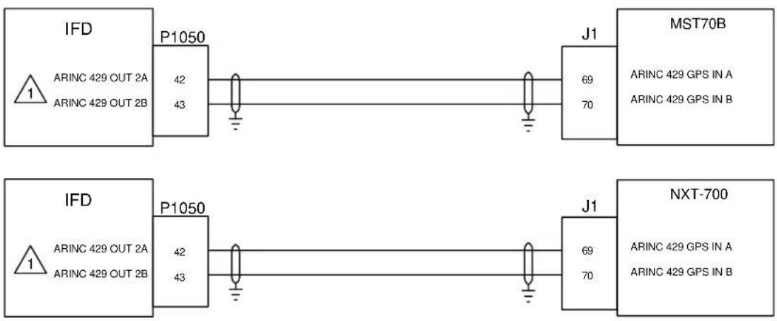
flowchart
graph LR
    A["IFD"] --> B["P1050"]
    B --> C["J1"]
    C --> D["MST70B"]
    A --> E["ARINC 429 OUT 2A"]
    A --> F["ARINC 429 OUT 2B"]
    B --> G["42"]
    B --> H["43"]
    C --> I["69"]
    C --> J["70"]
    D --> K["ARINC 429 GPS IN A"]
    D --> L["ARINC 429 GPS IN B"]
    M["IFD"] --> N["ARINC 429 OUT 2A"]
    M --> O["ARINC 429 OUT 2B"]
    N --> P["P1050"]
    O --> Q["42"]
    O --> R["43"]
    P --> S["J1"]
    Q --> T["69"]
    Q --> U["70"]
    V["NXT-700"] --> W["ARINC 429 GPS IN A"]
    V --> X["ARINC 429 GPS IN B"]
NOTES:
1 CONFIGURE MAIN ARINC 429 OUT 2 TO "ARINC 743A". SET SPEED TO LOW OR HIGH
Figure D - 56: NXT 700 MST70B Transponder Interconnect

NOTES:

CONFIGURE MAIN ARINC 429 OUT 2 TO "ARINC 743A". SET SPEED TO LOW OR HIGH.
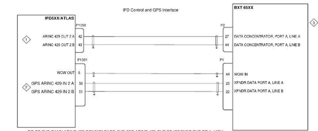
flowchart
graph TD
    A["IFD5XX/ATLAS"] -->|1| B["ARINC 429 OUT 2 A"]
    A -->|2| C["ARINC 429 OUT 2 B"]
    A -->|3| D["P1050"]
    A -->|42| E["P1001"]
    A -->|43| F["P2"]
    A -->|44| G["P1"]
    H["BXT 65XX"] -->|3| I["DATA CONCENTRATOR, PORT A, LINE A"]
    H -->|4| J["DATA CONCENTRATOR, PORT A, LINE B"]
    H -->|8| K["WOW OUT"]
    H -->|50| L["GPS ARINC 429 IN 2 A"]
    H -->|51| M["GPS ARINC 429 IN 2 B"]
    H -->|44| N["WOW IN"]
    H -->|23| O["XPNDR DATA PORT A, LINE A"]
    H -->|22| P["XPNDR DATA PORT A, LINE B"]
NOTES:

GO TO THE "MAIN ARINC 429 CONFIG" PAGE AND SET ARINC 429 OUT TO "BECKER BXT CTL", HIGH SPEED.

GO TO THE "MAIN ARINC 429 CONFIG" PAGE AND SET GPS ARINC 429 IN TO BECKER BXT, LOW SPEED.

USE THE EMP6100-BXT PROGRAMMER TO CONFIGURE TRANSPONDER TO SET:
1. WOW INPUT FOR ACTIVE LOW
2. DATA CONCENTRATOR INPUT FOR TRANSPONDER CONTROL AND GNSS RECEIVER INPUT.
3. ARINC 429 IN PORT TO HIGH SPEED AND OUT PORT TO LOW SPEED.
4. THE IFD SERIES CANNOT BE USED FOR BXT6XX CONTROL IF TCAS II IS INSTALLED
Figure D - 57: Becker BXT 65XX Interconnect
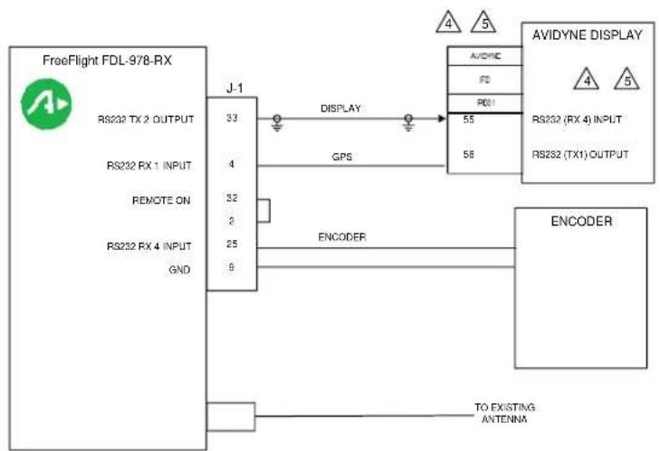
flowchart
graph TD
    A["FreeFlight FDL-978-RX"] -->|J-1 33| B["DISPLAY"]
    B --> C["AVIDYNE DISPLAY 4 5"]
    B --> D["RS232 (RX 4) INPUT 55"]
    B --> E["RS232 (TX1) OUTPUT 58"]
    A -->|RS232 TX 2 OUTPUT 4| F["ENCODER"]
    A -->|RS232 RX 1 INPUT 32| G["ENCODER"]
    A -->|RS232 RX 4 INPUT 25| H["ENCODER"]
    A -->|GND 9| I["ENCODER"]
    J["TO EXISTING ANTENNA"] --> K["ENCODER"]
NOTES:
- ALL WIRES TO BE 22 AWG OR GREATER UNLESS OTHERWISE NOTED.
- WIRE HARNESS OVERBRAID IS NOT SHOWN BUT MAY BE REQUIRED.
- REFER TO MANUFACTURER'S DOCUMENTATION FOR COMPLETE PINOUT AND INTERCONNECT INFORMATION.
4 IF RS-232 PORT 2 IS NOT AVAILABLE, USE ANY OTHER AVAILABLE PORT. USE OF PORT 3 FOR CAPSTONE PROTOCOLS SHOULD BE AVOIDED
5 SET IFD DISPLAY INPUT PORT TO CAPSTONE TRAFFIC & WX (38,400 BAUD), GPS OUTPUT PORT TO ADS-B+(G2) (38,400 BAUD).
Figure D - 58: FreeFlight FDL 978RX Interconnect

flowchart
graph LR
    A["IFD"] -->|GPS RS232 OUT 1
WX RS232 IN 1| B["P1001"]
    A -->|TIME MARK| C["P1050"]
    A -->|ARINC 429 IN 1A
ARINC 429 IN 1B| D["P1001"]
    A -->|TAWS AUDIO
ACTIVE OUT| E["P1050"]
    F["GARDMIN GDL88"] -->|RS232 IN 2
RS422 OUT 2B (-)
RS232 GND 245| G["P881"]
    F -->|TIME MARK 1A| H["P1001"]
    F -->|ARINC 429 OUT A
ARINC 429 OUT B| I["P1050"]
    F -->|AUDIO INHIBIT #1| J["P881"]
    F -->|4| K["Output"]

flowchart
graph TD
    subgraph IFD
        A["P1001"] --> B["P881"]
        C["GPS RS232 OUT 1\nWX RS232 IN 1"] --> D["IRIC"]
        E["TIME MARK OUT 16"] --> F["ARINC 429 IN 1A"]
        G["ARINC 429 IN 1B"] --> H["ARINC 429 IN 1B"]
        I["IRIC"] --> J["IRIC"]
        K["TIME MARK OUT"] --> L["ARINC 429 IN 1A"]
        M["ARINC 429 IN 1B"] --> N["ARINC 429 IN 1B"]
        O["IRIC"] --> P["IRIC"]
        Q["TIME MARK OUT"] --> R["ARINC 429 IN 1A"]
        S["ARINC 429 IN 1B"] --> T["ARINC 429 IN 1B"]
        U["IRIC"] --> V["IRIC"]
        W["TIME MARK OUT"] --> X["ARINC 429 IN 1A"]
        Y["TIME MARK OUT"] --> Z["ARINC 429 IN 1B"]
        AA["IRIC"] --> AB["IRIC"]
        AC["TIME MARK OUT"] --> AD["ARINC 429 IN 1A"]
        AE["TIME MARK OUT"] --> AF["ARINC 429 IN 1B"]
        AG["IRIC"] --> AH["IRIC"]
        AI["TAWS AUDIO\nACTIVE OUT"] --> AJ["TAWS AUDIO\nACTIVE OUT"]
    end
    subgraph GARMIN GDL88
        AK["GPS RS232 OUT 1\nWX RS232 IN 1"] --> AL["P1001"]
        AM["TIME MARK OUT"] --> AN["P1001"]
        AO["TIME MARK OUT"] --> AP["P1050"]
        AQ["GPS RS232 OUT 1\nWX RS232 IN 1"] --> AR["P1001"]
        AS["TIME MARK OUT"] --> AT["P1001"]
        AU["GPS RS232 OUT 1\nWX RS232 IN 1"] --> AV["P1001"]
        AW["TIME MARK OUT"] --> AX["P1001"]
        AY["GPS RS232 OUT 1\nWX RS232 IN 1"] --> AZ["P1001"]
        BA["TIME MARK OUT"] --> BB["P1001"]
        BC["GPS RS232 OUT 1\nWX RS232 IN 1"] --> BD["P1001"]
        BE["TIME MARK OUT"] --> BF["P1001"]
        BG["GPS RS232 OUT 1\nWX RS232 IN 1"] --> BH["P1001"]
        BI["TIME MARK OUT"] --> BJ["P1001"]
        BK["GPS RS232 OUT 1\nWX RS232 IN 1"] --> BL["P1001"]
        BM["TIME MARK OUT"] --> BN["P1001"]
        BO["GPS RS232 OUT 1\nWX RS232 IN 1"] --> BP["P1001"]
        BQ["GPS RS232 OUT 1\nWX RS232 IN 1"] --> BR["P1001"]
        BS["TIME MARK OUT"] --> BT["P1001"]
        BU["GPS RS232 OUT 1\nWX RS232 IN 1"] --> BV["P1001"]
        BW["TIME MARK OUT"] --> BX["P1001"]
        BY["GPS RS232 OUT 1\nWX RS232 IN 1"] --> BZ["P1001"]
        CA["TIME MARK OUT"] --> CB["P1001"]
        CC["GPS RS232 OUT 1\nWX RS232 IN 1"] --> DD["P1001"]
        DE["TIME MARK OUT"] --> DF["P1001"]
        DG["GPS RS232 OUT 1\nWX RS232 IN 1"] --> DH["P1001"]
        DI["GPS RS232 OUT 1\nWX RS232 IN 1"] --> DJ["P1001"]
        DK["TIME MARK OUT"] --> DL["P1001"]
        DM["GPS RS232 OUT 1\nWX RS232 IN 1"] --> DN["P1001"]
        DO["TIME MARK OUT"] --> DO
        DB["GPS RS232 OUT 1\nWX RS232 IN 1"] --> DB
        DC["TIME MARK OUT"] --> DC
        DD["TIME MARK OUT"] --> DD
        DBT["GPS RS232 OUT 1\nWX RS232 IN 1"] --> DU["P1050"]
    end
    subgraph Audio_INHIBIT#1
        DV["4"] --> DW["4"]
    end
NOTES:
1. ALL WIRES TO BE 24 AWG MINIMUM UNLESS OTHERWISE SPECIFIED.
2. ALL GROUND CONNECTIONS SHOWN FOR THE GDL88 ARE TO BE CONNECTED TO SHIELD BLOCK GROUND.
3. AT IFD UNIT, TERMINATE SHIELD GROUNDS TO THE CONNECTOR BACKSHELL OR USE CARD-EDGE CONNECTOR TO TERMINATE SHIELD GROUNDS TO BACK PLATE - THE SHIELD LEADS MUST BE LESS THAN 3.0 INCHES. CONNECT OTHER SHIELD GROUNDS TO AIRCRAFT CHASSIS WITH AS SHORT A CONDUCTOR AS PRACTICLE.

AUDIO INHIBIT MAY BE USED TO INHIBIT GDL88 ITS-B ALERTS DURING IFD FLT AURAL ANNUNCIATIONS. THIS DOES NOT AFFECT THE APPROVAL OF THE TIS-B FUNCTIONS OF THE GDL88. GDL88 AUDIO INHIBIT MAY BE DRIVEN BY THE IFD#1 OR IFD#2 IN DUAL IFD INSTALLATIONS. IFD4XX UNITS DO NOT DRIVE AUDIO INHIBIT. IN IFD4XX UNITS SIMULTANEOUS TIS-B AND FLT AURAL ANNUNCIATIONS ARE POSSIBLE (ADDRESSED IN AFMS).
5. IFD SERIAL PORTS (RS232 AND ARINC 429) OTHER THAN THE ONES SHOWN ABOVE MAY BE SUBSTITUTED WITH APPROPRIATE UNIT SOFTWARE CONFIGURATION.
6. CONFIGURE SELECTED PORTS WITH THE FOLLOWING SETTINGS;
IFD RS 232 OUTPUT SETTING: ADS-B+ (G2) GDL88 RS 232 INPUT SETTING: ADS-B FORMAT 2 (NOT REQUIRED IF GDL88 HAS INTERNAL GPS)
IFD RS 232 INPUT SETTING: CAPSTONE HS WX GDL 88 RS 422 INPUT/OUTPUT SETTING: OPTIMIZED LEGACY ADS-B
IFD ARINC 429 RX SETTING: GDL88 TRAFFIC AT HIGH SPEED GDL88 ARINC 429 TRANSMIT SETTING: TRAFFIC OUT AT HIGH SPEED
MINIMUM SOFTWARE VERSIONS REQUIRED: IFD XXX V10.2.1 OR HIGHER GDL 88 V3.33 OR HIGHER
7. THE IFD IS NOT AN APPROVED GPS POSITION SOURCE FOR GDL88 ADS-B OUT FUNCTIONALITY
Figure D - 59: GDL 88 Interconnect
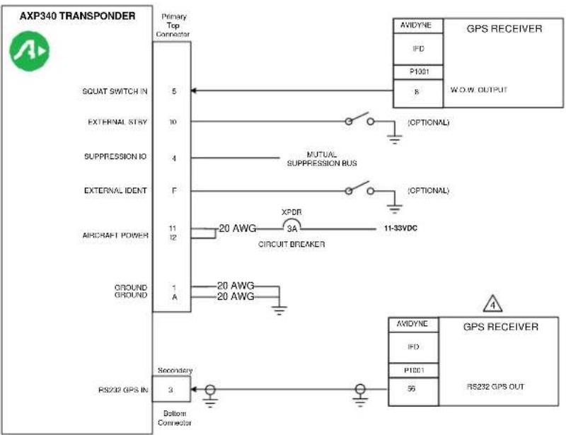
flowchart
graph TD
    A["AXP340 TRANSPONDER"] --> B["Primary Top Connector"]
    B --> C["SQUAT SWITCH IN 5"]
    B --> D["EXTERNAL STRY 10"]
    B --> E["SUPPRESSION IO 4"]
    B --> F["EXTERNAL IDENT F"]
    B --> G["AIRCRAFT POWER 11 12"]
    B --> H["GROUND GROUND 1 A"]
    B --> I["RS232 GPS IN Secondary 3"]
    I --> J["Bottom Connector"]
    C --> K["Optional"] --> L["AXIDYNE GPS RECEIVER"]
    D --> M["MUTUAL SUPPRESSION BUS"] --> N["IFD P1001 S"]
    F --> O["OPTIONAL"] --> P["P1001 W.OW. OUTPUT"]
    G --> Q["XDDR 3A CIRCUIT BREAKER"] --> R["11-33VDC"]
    H --> S["20 AWG 20 AWG"]
    I --> T["Secondary"] --> U["RS232 GPS OUT"]
    V["GPS RECEIVER"] --> W["AVIDYNE GPS RECEIVER"]
    V --> X["IFD P1001 S"]
    V --> Y["56 GPS OUT"]
NOTES:
1. ALL WIRES TO BE 24 AWG OR GREATER UNLESS OTHERWISE NOTED.
2. WIRE HARNESS OVERBRAID IS NOT SHOWN BUT MAY BE REQUIRED.
3. REFER TO MANUFACTURER'S DOCUMENTATION FOR COMPLETE PINOUT AND INTERCONNECT INFORMATION.
4F RS-232 PORT 1 IS NOT AVAILABLE, USE ANY OTHER AVAILABLE PORT.
Figure D - 60: Avidyne AXP340 Interconnect

flowchart
graph LR
    A["XMD076"] -->|37 Pin| B["IFD"]
    A -->|22 4| C["AUDIO PANEL Connections To Be determined by Installer"]
    A -->|21 2| C
    A -->|20 1| C
    A -->|18 19 37| C
    A -->|14 - 28 VDC in| C
    B -->|59 58| D["P1001"]
    D --> E["RS-232 INPUT"]
    D --> F["RS-232 OUTPUT"]
NOTES:
- ALL WIRES TO BE 22 AWG OR GREATER UNLESS OTHERWISE NOTED.
- IFD NEEDS SOFTWARE 10.2.3.1 OR HIGHER.
- IFD WILL NOT CONTROL AUDIO FUNCTIONS.
- WEATHER DISPLAY IS 115, 200 BAUD.
Figure D - 61: XMD076 Interconnect

flowchart
graph TD
    A["GDU 700/1060 PFD"] --> B["P4"]
    A --> C["P3"]
    A --> D["P4"]
    A --> E["P4"]
    A --> F["P4"]
    A --> G["P4"]
    A --> H["P4"]
    A --> I["P4"]

    J["IFD #1"] --> K["VOR/ILS 429 OUT A\nVOR/ILS 429 OUT B"]
    K --> L["TIME MARK OUT + TIME MARK OUT -"]
    L --> M["RS-232 OUT GROUND"]
    M --> N["GPS 429 OUT A\nGPS 429 OUT B"]
    M --> O["GPS 429 IN A\nGPS 429 IN B"]

    P["IFD #2"] --> Q["VOR/ILS 429 OUT A\nVOR/ILS 429 OUT B"]
    Q --> R["TIME MARK OUT + TIME MARK OUT -"]
    R --> S["RS-232 OUT GROUND"]
    S --> T["GPS 429 OUT A\nGPS 429 OUT B"]
    S --> U["GPS 429 IN A\nGPS 429 IN B"]

    V["IFD #1"] --> W["VOR/ILS 429 OUT A\nVOR/ILS 429 OUT B"]
    W --> X["TIME MARK OUT + TIME MARK OUT -"]
    X --> Y["RS-232 OUT GROUND"]
    Y --> Z["GPS 429 OUT A\nGPS 429 OUT B"]
    Y --> AA["GPS 429 IN A\nGPS 429 IN B"]

    AB["IFD #1"] --> AC["VOR/ILS 429 OUT A\nVOR/ILS 429 OUT B"]
    AC --> AD["TIME MARK OUT + TIME MARK OUT -"]
    AD --> AE["RS-232 OUT GROUND"]
    AE --> AF["GPS 429 OUT A\nGPS 429 OUT B"]
    AE --> AG["GPS 429 IN A\nGPS 429 IN B"]
NOTES:
- ALL WIRES TO BE 22 AWG OR GREATER UNLESS OTHERWISE NOTED.
- WIRE HARNESS OVERBRAID IS NOT SHOWN BUT MAY BE REQUIRED

THE TIME MARK B CONNECTION MUST BE LEFT UNCONNECTED FOR THE INSTALLATION OF IFD UNITS. A SINGLE CONDUCTOR SHIELDED WIRE MAY BE USED FOR THE TIME MARK IN THIS CASE
- SHOWN ARE CONNECTIONS TO THE IFD, ALL OTHER WIRING IS AT THE DISCRETION OF THE INSTALLER.
Figure D - 62: Single GDU700/1060 PFD Interconnect

flowchart
graph TD
    subgraph GDU 700/1060_PFD_1["PGD 700/1060 PFD #1"]
        A1["NAV1 ARINC 429 IN A NAV1 ARINC 428 IN B"] -->|P4| B1["7 27"]
        A2["TIME MARK IN 1A TIME MARK IN 1B RS-232 IN RS-232 GND"] -->|P3| B2["30 31"]
        A3["GPS1 ARINC 249 IN A GPS1 ARINC 429 IN B GPS1 ARINC 429 OUT A GPS1 ARINC 429 OUT B"] -->|P4| B3["5 25"]
        A4["TIME MARK IN 2A TIME MARK IN 2B RS-232 IN RS-232 GND"] -->|P3| B4["28 29"]
        A5["GPS2 ARINC 429 IN A GPS2 ARINC 429 IN B"] -->|P4| B5["5 26"]
    end

    subgraph_IFD_1["IFD #1"]
        C1["VORILS 428 OUT A VORILS 428 OUT B"] --> D1["P1006 24 23"]
        D1 --> E1["TIME MARK OUT + TIME MARK OUT - RS-232 OUT GROUND"]
        D1 --> E2["GPS 429 OUT A GPS 429 OUT B GPS 429 IN A GPS 429 IN B"]
    end

    subgraph GDU 700/1060_PFD_2["PGDU 700/1060 PFD #2"]
        F1["TIME MARK IN 1A TIME MARK IN 1B RS-232 IN RS-232 GND"] -->|P3| G1["30 31"]
        F2["GPS1 ARINC 429 IN A GPS1 ARINC 429 IN B"] -->|P4| H1["5 25"]
        F3["TIME MARK IN 2A TIME MARK IN 2B RS-232 IN RS-232 GND"] -->|P3| I1["28 29"]
        F4["GPS2 ARINC 249 IN A GPS2 ARINC 429 IN B"] -->|P4| J1["6 26"]
        F5["GPS3 ARINC 429 OUT A GPS3 ARINC 429 OUT B"] -->|P4| K1["8 28"]
        F6["NAV2 ARINC 428 IN A NAV2 ARINC 428 IN B"] -->|P4| L1["7 27"]
    end

    subgraph_IFD_2["IFD #2"]
        M1["TIME MARK OUT + TIME MARK OUT - RS-232 OUT GROUND"] --> N1["P1001 16 - 58 SWD"]
        N1 --> O1["GPS 429 OUT A GPS 429 OUT B GPS 429 IN A GPS 429 IN B"]
        N1 --> O2["P1006 24 23"]
    end
NOTES:
1. ALL WIRES TO BE 22 AWG OR GREATER UNLESS OTHERWISE NOTED.
2. WIRE HARNESS OVERBRAID IS NOT SHOWN BUT MAY BE REQUIRED
THE TIME MARK B CONNECTION MUST BE LEFT UNCONNECTED FOR THE INSTALLATION OF IFD SERIES UNITS. A SINGLE CONDUCTOR SHILDED WIRE MAY BE USED FOR THE TIME MARK IN THIS CASE
- SHOWN ARE CONNECTIONS TO THE IFD'S, ALL OTHER WIRING IS AT THE DESCRIPTION OF THE INSTALLER.
Figure D - 63: Dual GDU700/1060 PFD Interconnect

flowchart
graph TD
    A["G5 (HSI)\nRS-232 RX\nSIGNAL GROUND"] --> B["2P51"]
    B --> C["4"]
    B --> D["6"]
    E["GAD 29/29B"]\nARINC 429 RX 1A (GPS)\nARINC 429 RX 1B (GPS)\nARINC 429 TX 1A (EFIS/AIR DATA)\nARINC 429 TX 1B (EFIS/AIR DATA)\n3\nARINC 429 RX 2A (NAV)\nARINC 429 RX 2B (NAV)\nP292\n23\n11\n24\n12\n22\n10\nIFD\nRS-232 OUT\nRS-232 GND\n46\n47\n48\n49\nP1006\nARINC 429 OUT A\nARINC 429 OUT B\nARINC 429 IN A\nARINC 429 IN B\nP1006\nARINC 429 OUT A\nARINC 429 OUT B\nP1001\n56\nGND
NOTES:
1. ALL WIRES TO BE 22 AWG OR GREATER UNLESS OTHERWISE NOTED.
2. IFD NEEDS SOFTWARE 10.2.3.1 OR HIGHER.

GAD29B INSTALLED WHEN INTERFACING TO A THIRD PARTY AUTOPILOT SEE GAD29B INTERFACE TO THIRD PARTY AUTOPILOT INTERCONNECT DIAGRAMS FOR FURTHER INFORMATION.
| IFD Config Page | Config Option | Configuration Setting |
| MAIN ARINC 429 CONFIG Page | IN (x) | Speed = LowEFIS/AirData (Garmin Autopilot, No Autopilot)GAD42 (Analog Autopilots Only) |
| OUT | Speed = LowData = GAMA 429 | |
| VNAV | ENABLED | |
| MAIN RS-232 CONFIG Page | Input = OFFOutput = MapMX (WAAS GPS)AVIATION (non WAAS GPS) | |
| VOR/LOC/GS ARINC 429 CONFIG Page | RX = LowTX = LowVOR/ILS 1 | |
Figure D - 64: Garmin G5 EHSI Interconnect
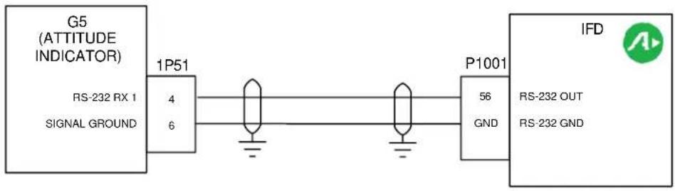
flowchart
graph LR
    A["G5 (ATTITUDE INDICATOR)"] -->|RS-232 RX 1| B["1P51"]
    B --> C["4"]
    B --> D["6"]
    C --> E["Ground"]
    D --> F["Ground"]
    G["P1001"] --> H["56"]
    G --> I["GND"]
    J["IFD"] --> K["RS-232 OUT"]
    J --> L["RS-232 GND"]
NOTES:
- ALL WIRES TO BE 22 AWG OR GREATER UNLESS OTHERWISE NOTED.
- WIRE HARNESS OVERBRAID IS NOT SHOWN BUT MAY BE REQUIRED.
| IFD Config Page Configuration Setting | |
| MAIN RS-232 CONFIG PAGE | Input = OFFOutput = MapMX (WAAS GPS)AVIATION (non WAAS GPS) |
Figure D - 65: Garmin G5 EADI Interconnect
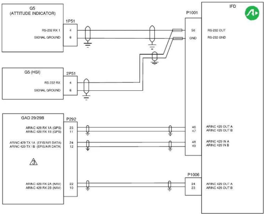
flowchart
graph TD
    subgraph G5 (ATTITUDE INDICATOR)
        A["RS-232 RX 1"] -->|4/6| B["Signal Ground"]
        C["RS-232 RX"] -->|4/6| D["Signal Ground"]
        E["RS-232 RX"] --> F["2P51"]
    end
    subgraph G5 (HSI)
        G["RS-232 RX"] --> H["Signal Ground"]
        I["GAD 29/29B"] --> J["ARINC 429 RX 1A (GPS)"]
    end
    subgraph GAD 29/29B
        K["ARINC 429 RX 1A (GPS)"]
    end
    subgraph IFD
        L["RS-232 OUT"] --> M["RS-232 GND"]
        N["ARINC 429 OUT A"] --> O["ARINC 429 OUT B"]
        P["ARINC 429 IN A"] --> Q["ARINC 429 IN B"]
        R["ARINC 429 OUT A"] --> S["ARINC 429 OUT B"]
    end
    A --> B --> C --> D --> E --> F --> G --> H --> I --> J --> K --> L --> M --> N --> O --> P --> Q --> R --> S --> T["22/10"]
    T --> U["23/11"]
    U --> V["24/12"]
    V --> W["25/13"]
    W --> X["26/14"]
    X --> Y["27/15"]
    Y --> Z["28/16"]
    Z --> AA["29/17"]
    AA --> AB["30/18"]
    AB --> AC["31/19"]
    AC --> AD["32/20"]
    AD --> AE["33/21"]
    AE --> AF["34/22"]
    AF --> AG["35/23"]
    AG --> AH["36/24"]
    AH --> AI["37/25"]
    AI --> AJ["38/26"]
    AJ --> AK["39/27"]
    AK --> AL["40/28"]
    AL --> AM["41/29"]
    AM --> AN["42/30"]
    AN --> AO["43/31"]
    AO --> AP["44/32"]
    AP --> AQ["45/33"]
    AQ --> AR["46/34"]
    AR --> AS["47/35"]
    AS --> AT["48/36"]
    AT --> AU["49/37"]
    AU --> AV["50/38"]
    AV --> AW["51/39"]
    AW --> AX["52/40"]
    AX --> AY["53/41"]
    AY --> AZ["54/42"]
    AZ --> BA["55/43"]
    BA --> BB["56/44"]
    BB --> BC["P1001"]
    BC --> BD["P1006"]
    BD --> BE["P1006"]
    BE --> BF["P1006"]
NOTES:
1. ALL WIRES TO BE 22 AWG OR GREATER UNLESS OTHERWISE NOTED.
2. IFD NEEDS SOFTWARE 10.2.3.1 OR HIGHER.

GAD29B INSTALLED WHEN INTERFACING TO A THIRD PARTY AUTOPILOT SEE GAD29B INTERFACE TO THIRD PARTY AUTOPILOT INTERCONNECT DIAGRAMS FOR FURTHER INFORMATION.
| IFD Config Page | Config Option | Configuration Setting |
| MAIN ARINC 429 CONFIG Page | IN | Speed = LowEFIS/AirData (Garmin Autopilot, No Autopilot)GAD42 (Analog Autopilot Only) |
| OUT | Speed = LowData = GAMA 429 | |
| VNAV | ENABLED | |
| MAIN RS-232 CONFIG Page | Input = OFFOutput = MapMX (WAAS GPS)Aviation (Non WAAS GPS) | |
| VOR/LOC/GS ARINC 429 CONFIG Page | SPEEDSDI | RX = LowTX = LowVOR/ILS 1 |
Figure D - 66: Garmin G5 EFIS Interconnect

flowchart
graph TD
    A["NGT9000R"] --> B["J1/P1"]
    B --> C["P1001"]
    C --> D["IFD"]
    D --> E["ARINC 429 GPS OUT ARINC 429 GPS OUT B"]
    B --> F["RS-232 RX1"]
    B --> G["RS-232 TX1"]
    B --> H["WOW/SQUAT/SPEED SWITCH - DISC 3 IN"]
    B --> I["RS-422 A (-)"]
    B --> J["RS-232 RX3"]
    B --> K["GROUND"]
    B --> L["DCM SDA"]
    B --> M["DCM SCL"]
    B --> N["DCM 3.3V"]
    B --> O["DCM GND"]
    B --> P["+14 VDC or +28 VDC in 1"]
    B --> Q["+14 VDC or +28 VDC in 2"]
    B --> R["14 or 28 V RETURN 1"]
    B --> S["14 or 28 V RETURN 2"]
    C --> T["ENCODER 4"]
    C --> U["CONFIGURATION MODULE"]
    U --> V["POWER IN"]
    U --> W["Red Black"]
    U --> X["Green Green"]
    U --> Y["Yellow Yellow"]
    U --> Z["Power IN"]
NOTES:
- ALL WIRES TO BE 22 AWG OR GREATER UNLESS OTHERWISE NOTED.
- WIRE HARNESS OVERBRAID IS NOT SHOWN BUT MAY BE REQUIRED
- CONFIGURE NGT9000R WOW INPUT TO OPEN IN AIR.

REFER TO THE INSTALLATION MANUAL OF THE ALTITUDE ENCODER FOR PINOUT AND FORMAT SETTINGS.
- CONFIGURE NGT9000R RS-232 OUT BAUD TO 115,200.*
- CONFIGURE IFD RS-232 INPUT TO CAPSTONE HS TFC&WX
- CONFIGURE THE IFD RS-232 OUTPUT/INPUT TO NGT9000R*
* See Lynx NGT-9000 Installation Manual P/N 0040-17001-01
- CONFIGURE OPTIONAL IFD GPS ARINC 429 OUTPUT TO ARINC 743A. PORT SPEEDS MUST MATCH
Figure D - 67: NGT9000R Interconnect

flowchart
graph TD
    A["KT-74 Primary J1"] -->|GPS POSITION IN 7| B["P1001"]
    A -->|SQUAT SWITCH IN 5| B
    A -->|11 to 33 VDC 11| C["IFD"]
    A -->|11 to 33 VDC 12| C
    A -->|SUPPRESS IN 9| C
    A -->|IDENT SWITCH IN 1| C
    A -->|GROUND GROUND 1| C
    A -->|GROUND GROUND A| C
    D["Secondary J2"] -->|SERIAL ALT IN 3| E["IFD"]
    D -->|SERIAL ALT IN GROUND 1| F["SERIAL ENCODER Pinout dependent on encoder Model"]
    B -->|RS-232 OUT 56| G["IFD"]
    B -->|wow| H["IFD"]
    E -->|X X| I["SERIAL ENCODER Pinout dependent on encoder Model"]
NOTES:
- ALL WIRES TO BE 22 AWG OR GREATER UNLESS OTHERWISE NOTED.
- WIRE HARNESS OVERBRAID IS NOT SHOWN BUT MAY BE REQUIRED.
- SET SQUAT SWITCH SETTING TO LOW WHEN GROUND.
- SET GPS POSITION SOURCE TO TRIG ADS-B AT 9600 BPS.
- SET GPS CERTIFICATION TO LEVEL C.
- SET GPS NACv TO 1 OR < 10m/SECOND.
- SET THE IFDXXX/ATLAS OUTPUT TO ADS-B (AVI).
- PARALLEL ALTITUDE WIRING, NOT SHOWN, CAN BE USED IN PLACE OF SERIAL ALTITUDE.
Figure D - 68: KT-74 Interconnect
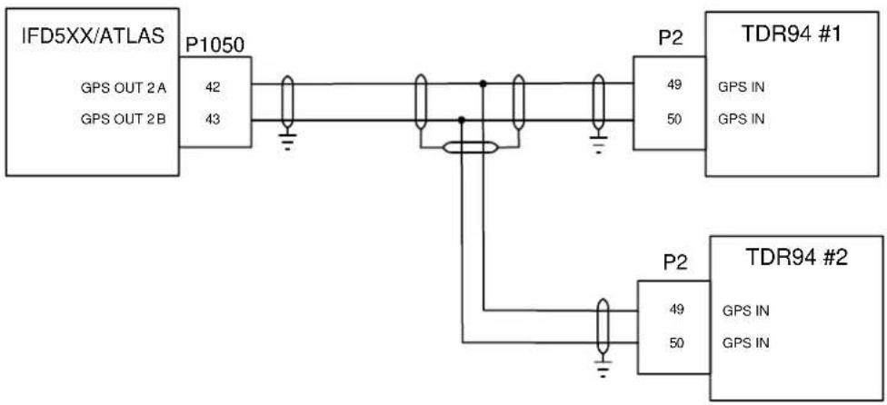
flowchart
graph LR
    A["IFD5XX/ATLAS"] -->|P1050| B["TDR94 #1"]
    A -->|42 43| C["TDR94 #2"]
    B -->|49 50| D["TDR94 #1"]
    B -->|49 50| E["TDR94 #2"]
    style A fill:#f9f,stroke:#333
    style B fill:#ccf,stroke:#333
    style C fill:#cfc,stroke:#333
    style D fill:#fcc,stroke:#333
    style E fill:#fcc,stroke:#333
NOTES:
- ALL WIRES TO BE 22 AWG MINIMUM UNLESS OTHERWISE SPECIFIED.
- WIRE HARNESS OVERBRAID IS NOT SHOWN BUT MAY BE REQUIRED.
- CONFIGURE IFDXXX/ATLAS ARINC 2 OUT TO HIGH SPEED, ARINC 743A. VERIFY THAT THE TDR94 PORT SPEED IS SET TO HIGH SPEED
- SHOWN IS THE CONNECTIONS TO THE IFD. ALL OTHER WIRING IS AT THE DISCRETION OF THE INSTALLER.
Figure D - 69: TDR-94 Interconnect


flowchart
graph LR
    A["IFD4XX/5XX"] -->|A429 VOR/ILS OUT\nA429 VOR/ILS OUT| B["P1006"]
    B -->|24\n23| C["P2751"]
    C -->|72\n14| D["GI-275"]
    D -->|A429 IN 2A\nA429 IN 2B| E["Ground"]
Notes:
- IFD CONFIGURATIONS:
a. IFD GPS ARINC429 OUT: GAMA429
b. IFD GPS ARINC429 IN: GARMIN GDU
c. IFD GPS SDI: LNAV1 for IFD#1; LNAV2 for IFD#2
d. IFD VNAV: Enable Labels
e. IFD VOR/ILS 429 OUT: VHF 429
f. IFD VOR/ILS SDI: VOR/ILS1 or IFD#1;VOR/ILS2 for IFD#2
Figure D - 70: Garmin GI-275 Interconnect
Appendix E: Troubleshooting Guide
| Component | Trouble | Probable Cause | Solution |
| IFD5XXIFD4XXATLAS | The unit is not getting power to the main connector | The unit is not getting power. | Check Circuit Breaker |
| Check wiring and unit seating in tray | |||
| The IFD is not computing a position | Wiring | Check Coaxial Cables | |
| Antenna | Verify antenna has a clear unobstructed view of the sky | ||
| The GPS Signal levels are very low | Wiring | Check coaxial cable and connectors | |
| Check routing | |||
| Antenna shading | Verify the antenna is mounted on top of the aircraft | ||
| Verify antenna is clear of hangars, buildings, etc. | |||
| Interference | Verify another piece of aircraft equipment is not interfering with the GPS system | ||
| VHF Com is not transmitting (NOT APPLICABLE FOR IFD410/510/545 OR ATLAS FMS ONLY UNITS) | Wiring | Check the aircraft's PTT switch | |
| Check Audio Panel (if installed) | |||
| Check wiring | |||
| The IFD5XX/4XX is not tuning the DME(NOT APPLICABLE FOR IFD410/510/545 OR ATLAS FMS ONLY UNITS) | Configuration | Verify the IFD5XX/4XX is configured correctly. | |
| Wiring | Checking wiring | ||
| DME | Verify the DME is configured for the IFD5XX/4XX tuning type | ||
| RS-232 Device is not communicating | Configuration | Verify the IFD5XX/4XX is configured for the appropriate device. | |
| Wiring | Check wiring and unit seating in tray | ||
| ARINC 429 is not communicating | Configuration | Verify the IFD5XX/4XX is configured for the appropriate device. | |
| Wiring | Check wiring and unit seating in tray | ||
| IFD5XXIFD4XXATLAS | Display appears excessively dim or off | Configuration (configured for "night mode") | Check cockpit dimming rheostat position |
| Check Flight Mode settings on User Options page for Display and Bezel Brightness and source | |||
| Check power button on IFD | |||
| Check Mx Mode settings on Lighting page for proper setting | |||
| CMOS Battery Dead CAS Message | The 10-year life expectancy of the CMOS battery has been reached. This may result in longer GPS satellite acquisition times. | Return the IFD to Avidyne Service Center for battery replacement | |
| VHF Radio Slots displaying Red-Xs(NOT APPLICABLE FOR IFD410/510/545 OR ATLAS FMS ONLY UNITS) | No power on the P1002 ConnectorChassis ID not set to 0 or 1 | Ensure all governing circuit breakers have power | |
| Check and set as required the Chassis ID per section 7.3 | |||
| Unit starts up in Maintenance Mode | USB fob installed at power upIFD last shut down in Maintenance Mode | Ensure fob is not in the USB slot and reapply power to the IFD | |
| Press the left or right side of the AUX page until the "DONE" Line Select Key is visible and press that LSK to force the IFD to restart into flight mode | |||
| Unable to get out of Maintenance Mode or not sure how to | Press the left or right side of the AUX page until the "DONE" Line Select Key is visible and press that LSK to force the IFD to restart into flight mode | ||
| IFD to IFD Communication is not functional as indicated by either "CROSSYNC FAIL" CAS message or no data sharing observed between the IFDs | IFD is misconfiguredWiring incorrect | Ensure RS-232 Channel 3 is set to CrossSync on each IFD | |
| Ensure serial Channel 3 wiring is installed per Section 4.7 | |||
| "Config Mismatch" CAS message on IFD5XX/4XX (dual IFD5XX/4XX/ATLAS only) | Configuration mismatch between the two IFD units | Power cycle the IFD unitsVerify configuration on IFD5XX/4XX unitsIf problem persists, send IFD5XX/4XX log data to Avidyne Technical Support | |
| “No Comm with” whereis an attached device | Device is not wired correctly or RS232 or ARINC429 connection is on a port other than what is configured in Maintainace mode | Confirm device is poweredCheck wiringConfirm wired port maches configured port |
Appendix F: Configuration Setup
In order to support the requirements of some validations of the AML STC, this section should be easily removable and inserted into the aircraft logs.
For those installations where an IFD is replacing a GNS-530/W or GNS-430, please record the following parameters from the GNS-530/W or GNS-430/W setup pages before removing the unit (Note: this will need to be conducted for each GNS-530/W or GNS-430/W being replaced):
WAAS Enabled (530W or 430W with approved antenna)? Yes □ No □ 2nd unit: Yes □ No □ N/A □
530/W or 430/W Hardware Part Number and Revision Number (back of unit or aircraft logs) ____/____
530/W or 430/W Software Part Number ("Main SW Version" on start up splash screen) ____/____
If multiple GNS-530/W or GNS-430/W were installed, describe the slot/location that this specific unit was removed from.
Cockpit Location of Unit(s) in Question
| Description of location/slot in the cockpit (Include rough sketch if deemed helpful) |
Measure the distance from the ground to the top of the GPS antenna to nearest tenth of a foot, as shown in the image below, and enter the value in the box below: (to the nearest 1/10^th foot).
| Measured Height of GPS Antenna |

Please list the other avionics that are installed in the aircraft (please be as specific as possible with make and models of the gear) and connected to the GNS-530/W or GNS-430/W. Enter "None" or "Don't Know" as required. The GNS-530/W or GNS-430/W Setup pages will be captured on subsequent pages.
Identification of Devices Connected to the GNS-530/W or GNS-430/W
| 1^st GNS 530/W or GNS 430/W | 2^nd GNS 530/W or GNS-430/W (if applicable) | |
| Traffic | ||
| Datalink | ||
| Lightning Sensor | ||
| Autopilot | ||
| Fuel Flow System | ||
| Display(s) | ||
| CDI(s) | ||
| RMI(s) | ||
| Transponder | ||
| DME | ||
| ADF | ||
| Air Data | ||
| IRU/INS | ||
| Other | ||
| Other | ||
| Other |
Please list the other avionics that are installed in the aircraft and connected to the IFD. Enter "None" or "Don't Know" as required. The IFD Setup pages will be captured on subsequent pages.
Identification of Devices Connected to the IFD at time of Install
| 1^st IFD | 2^nd IFD (if applicable) | |
| Traffic | ||
| Datalink | ||
| Lightning Sensor | ||
| Autopilot | ||
| Fuel Flow System | ||
| Display(s) | ||
| CDI(s) | ||
| RMI(s) | ||
| Transponder | ||
| DME | ||
| ADF | ||
| Air Data | ||
| IRU/INS | ||
| Other | ||
| Other | ||
| Other |
GNS-530/W or GNS-430/W Maintenance Mode Entry:
GNS-530 configuration data is accessed from the GNS-530/W Maintenance Mode settings which are entered via holding ENTR button on 530/W bezel during power application.
GNS-530/W or GNS-430/W Page Navigation:
Use the inner right knob on the GNS-530/W to scroll through the maintenance mode pages. Each clockwise click of the knob selects the next page. On pages where selectable fields exist, a push of the right knob will produce a flashing cursor. The outer right knob moves through the fields on a page when there is a flashing cursor. Twist the inner right knob clockwise to see a list of choices. Use the inner right knob to scroll through the list of choices and press the "ENT" button to select the desired choice.
IFD Maintenance Mode Entry:
IFD configuration data is accessed via Mx Mode which is entered by starting the IFD with a USB Fob already installed or selecting the AUX page, SYS tab, ensuring that the "Select" LSK = Software, and then pressing the "Download Logs" LSK, followed by the "Confirm" LSK. These tables contain all the data that can be entered at time of installation to ensure the IFD is properly configured. There are additional setup options that selectable by the pilot (Display Options on AUX Setup tab) that are not documented here.
IFD Page Navigation:
To reach the IFD pages on which this data is to be entered, select the CONFIG tab in Maintenance Mode. Use the outer right knob to select the page - each clockwise click of the outer right knob selects the next page in the list. Push the right knob in to generate a cursor and then use the outer right knob to select an individual field with the cursor. Then twist the inner right knob to scroll through the selectable options for that field and push in the right knob when done with each field selection.
For retrofit installations (those installations in which an IFD is replacing a GNS-530/W or GNS-430/W), enter the data in the following tables/menu pages from the corresponding fields recorded below in the GNS-530/W or GNS-430/W tables on the left side of each page. Repeat for each retrofit IFD.
For new installations (those installations in which an IFD is NOT replacing a GNS-530/W or GNS-430/W), select and record the appropriate settings for each configuration page per the descriptive material below each table.
Garmin 530/W or 430/W - MAIN ARINC 429 CONFIG page
| Speed | Data | |
| IN 1 | ||
| IN 2 | ||
| OUT | ||
| SDI | ||
| VNAV(if present) | ||
IFD - Main ARINC 429 Config Page (1/12)
| Speed | Data | |
| In 1 | ||
| In 2 | ||
| Out | ||
| SDI | ||
| VNAV | ||
For new IFD5XX/ATLAS installations, see Section 7.5 for selections and descriptions
GNS-530/W or 430/W - MAIN RS232 CONFIG Page
| Input | Output | |
| CHNL 1 | ||
| CHNL 2 | ||
| CHNL 3 | ||
| CHNL 4 | ||
| CHNL 5 |
IFD - Main RS232 Config Page (2/12)
| CHNL 3 | ||
| CHNL 4 | ||
| CHNL 5 | ||
| CHNL 6 |
For new IFD5XX/ATLAS Installations, see Section 7.5.4 for selections and descriptions. IFD4XX do not have Channels 5 and 6.
| Input | Output | |
| CHNL 1 | ||
| CHNL 2 |
GNS-530/W or 430/W - MAIN SYSTEM CONFIG Page (Fuel)
| CONFIGURE | Fuel |
| FUEL TYPE |
IFD—Main System Config Page (3/12)
Tail Number is a free text field and is used for JSUM and Paid Options
GNS-530/W or 430/W – MAIN SYSTEM CONFIG Page (Terrain) [if present]
| CONFIGURE | Terrain |
| TERRAIN TYPE | |
| TEST CARD? | |
| HW CONFIG | |
| 012-00296- | |
| 012-00401- |
GNS-530/W or 430/W- MAIN SYSTEM CONFIG Page (Discretes) [if present]
| CONFIGURE | Discretes |
| GPS SELECT | |
| COM PRESETS |
Note: Com Presets are always enabled on the IFD
| Fuel Type | |
| GPS Select | |
| Airframe | |
| Tail Number | |
| External TAWS | |
| WOW Input (Helo) | |
| Checklists | |
| TIS-B Annunciation | |
| Joystick Input | |
| Appr Roll Steer | |
| Nav Radio Active |
GNS-530/W or 430/W- MAIN SYSTEM CONFIG Page (Airframe) [if present]
| CONFIGURE | Airframe |
| AIRFRAME | |
| AIR/GROUND(if present) |
Note: The Air/Ground selection is only present when helicopter is selected for the airframe and is a trigger to look for squat switch input. No equivalent in IFD.
GNS-530/W or 430/W - MAIN INPUTS Page
| OAT | HDG | BALT | |||
| SAT | W DIR | DALT | |||
| TAT | GPS SC | PALT | |||
| IAS | VLC SC | L FF | |||
| TAS | CDI | R FF | |||
| W SPD | T FF | ||||
| TFOB | |||||
| JOYSTICK WPT |
IFD - MAIN INPUTS Page (4/12)
| OAT | HDG | BALT | |||
| SAT | WDIR | DALT | |||
| TAT | GPSC | PALT | |||
| IAS | VLCSC | LFF | |||
| TAS | CDI | RFF | |||
| W SPD | TFF | ||||
| TFOB | |||||
| JOYSTICKWPT |
Note: There is no data to enter on the IFD from this page – it is for diagnostics only
GNS-530/W or 430/W – INSTRUMENT PANEL SELF TEST (For reference only)
| CDI | FUEL CAPACITY | |
| FLG | ||
| VCDI | FUEL ON-BOARD | |
| VFLG | ||
| TO/FRM | FUEL FLOW | |
| ANNUN | ||
| RMI | Set Fuel Flow? | |
| OBS | ||
| DTK |
No IFD Equivalent Page
GNS-530/W or 430/W- MAIN LIGHTING Page
| Display | Key | |||
| LIGHTING | ||||
| SOURCE | ||||
| RESP TIME /MIN | ||||
| SLOPE/ OFFSET | ||||
| PHOTO TRANS % (if applicable) | ||||
| PHOTO SLP/OFST (if applicable) | ||||
IFD - MAIN LIGHTING Page (5/12)
| Bezel | Display | ||
| Photo Response Time | |||
| Photo Slope | |||
| Photo Minimum | |||
| Photo Maximum | |||
| dimBus Transition % | |||
| dimBus Slope | |||
| dimBus Minimum | |||
| dimBus Maximum | |||
| dimBus Curve | |||
| Current Lighting | Dimming Bus Calibration | ||
| Bezel | dimBus Type | ||
| Display | dimBus Max Voltage | ||
| Mx Input | dimBus Min Voltage | ||
See Section 7.5.7 for instructions on this page.
GNS-530/W or 430/W - DATE / TIME SETUP
Page (No Need to Fill In - For Reference Only)
| UTC DATE | UTC TIME |
No IFD5XX/4XX/ATLAS Equivalent Page
GNS-530/W or 430/W - MAIN DISCRETE I/O Page
| GRAY CODE | DECODED ALTITUDE | ||||
| EXTERNAL SWITCH STATE | |||||
| RMT CDI ☐ | OBS ☐ | ||||
| DISCRETE TOGGLE | |||||
| APR ☐ | OBS ☐ | ILS/GPS APR ☐ | |||
| GPS ☐ | TERM ☐ | ||||
| INTEG ☐ | VLOC ☐ | ||||
| MSG ☐ | WPT ☐ | ||||
Note: Check off the squares, as required, to match the solid squares on the GNS-530/430 unit – these check that discretes are wired correctly.
IFD - MAIN DISCRETE I/O Page (6/12)
| GRAY CODE | DECODED ALTITUDE | ||||
| EXTERNAL SWITCH STATE | |||||
| RMT CDI ☐ | RMT OBS ☐ | RMT RCL ☐ | |||
| TER INHB ☐ | AUD INHB ☐ | ||||
| DISCRETE TOGGLES | |||||
| APR ☐ | OBS ☐ | ILS/GPS APR ☐ | |||
| GPS ☐ | TERM ☐ | GPS SELECT ☐ | |||
| INTEG ☐ | VLOC ☐ | TER CAUT ☐ | |||
| MSG ☐ | WPT ☐ | TER INHB ☐ | |||
| TER N/A ☐ | |||||
| TER WARN ☐ | |||||
Note; ON or OFF will be Displayed
GNS-530/W or 430/W - MAIN CDI / OBS CONFIG Page
| CDI | NAVFLAG | TO-FROM | |
| LAT | |||
| VERT | |||
| SELECTED COURSE | |||
| CDI | OBI SOURCE | V-FLAG STATE | |
IFD - MAIN CDI / OBS CONFIG Page (7/12)
| CDI | NAVFLAG | TO-FROM | |
| LAT | |||
| VERT | |||
| SELECTED COURSE | |||
| IgnoreSEL CRSfor GPS | |||
| IgnoreSEL CRSforVLOC | |||
| CDI | OBI SOURCE | V-FLAGSTATE | |
For new IFD installations, see Section 7.5.9 for selections and descriptions.
GNS-530/W or 430/W – COM SETUP Page (GNS-530W/430W Only)
| FREQ | SQ 250 | ||
| SPACING | SQ 833 | ||
| SIDETN | |||
| MIC | |||
| STORE CALIBRATION? | |||
| PTT ☐ XFR | ☐ ☐ | TX ☐ | |
Note: The squares above do not need to be recorded - they fill in when/if that function is activated.
No IFD Equivalent Page
(Use the User Options tab to select 25 or 8.33 kHz spacing)
GNS-530/W or 430/W - VOR/LOC/GS CDI Page
| CDI | NAVFLAG | SPRFLAG | TO-FROM | |
| LAT | ||||
| VERT | ||||
| SELECTED COURSE | ||||
| DMECHANNELMODE | ||||
GNS-530W or GNS-430W Only
IFD - VOR/LOC/GS CDI Page (8/12)
| CDI | NAVFLAG | SPRFLAG | TO-FROM | |
| LAT | ||||
| VERT | ||||
| SELECTED COURSE | ||||
| DME CHANNEL MODE | ||||
For new IFD installations, see Section 7.5.10 for selections and descriptions.
GNS-530/W or 430/W - VOR/LOC/GS ARINC 429 CONFIG Page (GNS-530W/430W Only)
| RX | TX | |
| SPEED | ||
| SDI | ||
| DMEMODE | ||
IFD - VOR/LOC/GS ARINC 429 CONFIG Page (9/12)
| RX | TX | |
| SPEED | ||
| FORMAT | ||
| SDI | ||
| DME MODE | ||
For new IFD installations, see Section 7.5.11 for selections and descriptions
GNS-530/W or 430/W– GPS Vertical Offset (if present)
| GPS Antenna HeightAbove Ground |
IFD - GPS Antenna Setup Page (10/12)
| GPS Antenna HeightAbove Ground | |
| Antenna Type |
Note: Use the data recorded at the beginning of Appendix F to enter the Antenna Type field.
GNS-530/W or 430/W—STORMSCOPE CONFIG Page (if configured for Stormscope)
| STATUS: | MODE: |
| SW VERSION: | ANT MOUNT: |
| HDG FORMAT | HDG FLG SENSE |
| ☐ HDG FLAG | ☐ SYNC ANGLE |
| ☐ HDG STAB | ☐ SYNC REF |
| ☐ HDG VALID |
Note: Squares should all be green if no issues.
IFD STORMSCOPE CONFIG Page (Software version 10.2 or higher)
Accessible via the TEST page, select GET DATA, scroll to Config, and record the jumpers installed and grounded
| HEADING INPUT | J3-1 □ OPEN □ GND J3-2 □ OPEN □ GND |
| HEADING FLAG SENSE | J3-4 □ OPEN □ GND |
| ANTENNA MOUNT | J3-3 □ OPEN □ GND |
GNS-530/W or 430/W - STORMSCOPE TEST Page (if configured for Stormscope)
| MODE |
| STATUS |
| TRIGGER COUNT |
| HDG |
IFD - STORMSCOPE TEST Page
(Software version 10.2 or higher)
| MODE |
| STATUS |
| TRIGGER COUNT |
| HDG |
GNS-530/W or 430/W- STORMSCOPE DATA DOWNLOAD Page (if configured for Stormscope)
| SOFTWARE VERSIONS: | |
| Model | |
| Main SW Ver | |
| Main Boot SW Ver | |
| DSP SW Ver |
IFD - STORMSCOPE DATA Page (Software version 10.2 or higher)
| SOFTWARE VERSIONS: | |
| Model | |
| Main SW Ver | |
| Main Boot SW Ver | |
| DSP SW Ver |
GNS-530/W or 430/W – Traffic Config Page (if configured for Traffic)
| ALT | |
| LIM A (if 429 interface) | |
| LIM B (if 429 interface) | |
| HDG (if 429 interface) | |
| BARO ALT □ (if 429 interface) | |
| RAD ALT □ (if 429 interface) | |
| TEST MODE? (if 429 interface) | |
No IFD Equivalent Page
Note: Traffic monitoring is accomplished after a 3 minute suppression period in-flight when any faults are announced. There should be no Red-X on the traffic thumbnail if configured on the Setup pages.
Note: Check off the squares, as required, to match the solid squares on the GNS-530 unit.
GNS-530/W or 430/W– RYAN TCAD CONFIG Page (if configured for Ryan TCAD)
| MODE | |
| APPROACH MODE | |
| HEIGHT | |
| RANGE | |
| GND/FLD ELEVATION | |
| VOLUME | |
| MUTE DURATION | |
| VOICE ALERT | |
| UNKNOWN DEVICE | □STATUS□MUTE |
No IFD Equivalent Page
Note: Use the presence of the traffic thumbnail and the Audio Volume Control page to control these parameters in the IFD.
GNS-530/W or 430/W – GAD 42 Config Page (if configured for an ARINC 429 input from GAD 42)
| MAIN RMI/OBI | ROLL STEERING | ||
| NAV RMI/OBI | REMOTE CRS SEL | ||
| SEL CRS DRIVE | TAS INPUT | ||
| DIST SERIAL | GPS/NAV 429 L/H | ||
| HEADING 429 L/H | |||
| GAD SW VER: | |||
| STATUS: | |||
No IFD Equivalent Page
Note: Manually strap the GAD42 or ensure stored configuration is not lost. The IFD5XX/4XX alerts in flight mode if the GAD42 reports a fault.
GNS-530/W or 430/W- TAWS Audio Config Page 1 (if installed)
| TAWS CONFIG | |
| VOICE GENDER | |
| VOLUME | |
| PLAY AUDIO MSG |
No IFD Equivalent Page
(Use the User Options LSK and Volume Control LSK of the Audio Tab instead)
GNS-530/W or 430/W – TAWS Audio Config Page 2 (if installed)
| ALERT | Reduced Terrain Clearance |
| CAUT | |
| WARN | |
| ALERT | Reduced Obstacle Clearance |
| CAUT | |
| WARN | |
| ALERT | Imminent Terrain Impact |
| CAUT | |
| WARN | |
| ALERT | Imminent Obstacle Impact |
| CAUT | |
| WARN |
No IFD Equivalent Page
(Use the User Options Tab instead)
GNS-530/W or 430/W – GDL Config Page (if installed)
| ATTENUATION | |
| MODEL (ifdisplayed) |
IFD - GDL Config Page (if installed) (11/12)
| ATTENUATION | |
| MODEL |
GNS-530/W or 430/W – DATALINK DIAGNOSTICS Page (if installed)
| QOS | TERR |
| SAT 1 | SAT 2 |
| TUNER | |
IFD Equivalent Page
Note: Use the Datalink Status page on the AUX-SYS tab for datalink status data.
Notice:
SOFTWARE LICENSE: AVIDYNE CORPORATION ("AVIDYNE") IS WILLING TO LICENSE THIS SOFTWARE, AND RELATED MATERIALS (THE "SOFTWARE") ONLY ON THE CONDITION THAT THE USER AGREES TO THE TERMS OF THE PUBLISHED SOFTWARE LICENSE WHICH CAN BE ACCESSED VIA THIS WEB ADDRESS:
HTTP://WWW.AVIDYNE.COM/SUPPORT/LICENSE.ASP
FCC APPROVAL AND CAUTIONS: THIS DEVICE COMPLIES WITH PART 15 OF THE FCC RULES. OPERATION IS SUBJECT TO THE CONDITION THAT THIS DEVICE DOES NOT CAUSE HARMFUL INTERFERENCE. THE MANUFACTURER IS NOT RESPONSIBLE FOR ANY RADIO OR TV INTERFERENCE CAUSED BY UNAUTHORIZED MODIFICATIONS TO THIS EQUIPMENT. SUCH MODIFICATIONS COULD VOID THE USER'S AUTHORITY TO OPERATE THE EQUIPMENT.
AVIDYNE ^TM
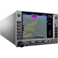


- AVIDYNE™
- IFD5XX / IFD4XX / Atlas Integrated Flight Display
- Installation Manual
- Table of Contents
- General Information 14
- Installation Considerations...... 48
- Antenna Installation 63
- VHF Communication Antenna 71
- Navigation Antennas.... 71
- Glideslope Antenna 72
- Electrical Installation....73
- IFD Connectors.... 74
- Byteflight Digital Data Bus Consideration – Dual IFD Installations 75
- Mechanical Installation 78
- System Installation.... 86
- Fixed Wing TAWS Annunciators 112
- Configuration and Checkout 122
- Checkout.... 179
- Flight Checks.... 184
- Glove Validation Procedures.... 186
- Software and Database Update Procedures...... 187
- Periodic Maintenance.... 193
- Factory Service Policies and Procedures...... 194
- Bezel and Display Cleaning 196
- Appendix A: Environmental Qualification Form...... 197
- Appendix B: STC Permission 200
- Notes to Installers:
- General Information
- Introduction
- IFD Configurations
- Unit Modifications
- Technical Specifications
- IFD5XX Specifications
- IFD4XX Specifications
- IFD4XX Physical and Electrical Specifications
- Atlas Specifications
- Atlas ARS (Inertial Reference) Specifications
- Regulatory Compliance
- Applicable TSOs
- Non-TSO Functions
- Partial TSO Functions
- Open Problem Report
- Software and Hardware Design Assurance Levels
- Environmental Qualification Forms
- Databases
- Electronic Map Display Information
- GPS Fault Detection and Exclusion (FDE)
- Terrain Alerting and Warning System
- FIS-B ADS-B Weather Information
- Part 23 STC Approved Model List
- Part 25 STC Approved Model List
- Avidyne Supplied Material
- Product Ship Kits
- Materials Required but not Supplied
- Installation Considerations
- VFR Installation
- IFR Installation
- Aircraft Categories
- IFD/Atlas Equipment
- Approved IFR Operations
- GPS Oceanic / Remote Navigation
- Garmin GNS Replacement Considerations
- Circuit Breakers
- WAAS Enabled:
- TAWS:
- TAWS Audio:
- Installation with Avidyne AXP340/322 Transponder:
- Additional Installation Data Sources
- Electrical Load Analysis (ELA)
- Optional Installation Features
- IFD Interfaces
- Pre-Installation Checklist
- Antenna Installation
- Antenna Bonding
- Antenna Environmental Qualifications
- GPS Antenna
- GPS Antenna Location:
- Doubler Fabrication:
- GPS Antenna Location
- Aircraft Lightning Zone Approved Locations
- Procedure:
- Example:
- GPS Antenna Bonding
- GPS Antenna Cable
- GPS Coaxial Cable Connector
- Approved GPS Antennas
- GPS Interference
- Ground Plane
- Dual IFD Installations
- Anti-Ice Protection
- VHF Communication Antenna
- Antenna Environmental Qualifications
- VHF Communication Cable
- VHF Coaxial Cable Connector
- Voltage Standing Wave Ratio
- VHF Antenna
- Antenna Ground Plane
- Navigation Antennas
- VOR/LOC Antenna
- Navigation Coaxial Cable
- Navigation Coaxial Cable Connector
- Diplexer
- Glideslope Antenna
- Glideslope
- Electrical Installation
- Wire Type
- Wire and Connector Identification
- Wire Routing
- Shield Grounds
- Wire Harness Overbraid
- Existing Equipment
- Severe Lightning Transient Environment
- Copper Overbraid Installation
- IFD Connectors
- Byteflight Digital Data Bus Consideration – Dual IFD Installations
- Databus Wiring - Replacement Installations
- Databus Wiring – New Installations
- Circuit Protection
- Power Distribution
- Electrical Load Analysis
- Low Power Behaviors
- Mechanical Installation
- Equipment Location – New Installations
- Determining the IFD Field of View
- Navigation and TAWS (if enabled) Annunciation
- Course Deviation Indicator
- Instrument Panel Cutout
- Requirements for Tray Installation
- Equipment Location - Replacement Unit
- Equipment Location - Atlas Unit
- Angle of Regard
- Unit Installation/Removal
- IFD IFD5XX/4XX Installation/Removal
- Atlas Installation/Removal
- Internal Cooling
- External Cooling
- Electrical Bonding
- Aircraft Considerations
- Weight and Balance
- Compass Safe Distance
- System Installation
- Pin Function List
- P1001 Main Connector
- P1002 Communication Connector
- P1006 Navigation Connector
- P1050 Additional I/O Connector
- Altitude Gray Code
- Heading Input
- Main Course Deviation Indicator Output
- Lateral/Vertical Deviations
- TO/FROM Indication Flag
- Navigation Flags
- Navigation Superflags
- OBS
- Annunciators Electrical Output
- Switch Inputs
- Serial Data
- ARINC 429
- GPS ARINC Output
- VHF ARINC Output
- Onboard Radar ARINC Output
- IFD Series Installation Manual
- ARINC 453
- RS170 Video
- Com/VOR/ILS Audio Electrical Characteristics
- Com Microphone Key
- VOR/ILS Indicator Electrical Characteristics
- Superflag
- RMI/OBI Electrical Characteristics
- DME Tuning
- Bezel Lighting
- Traffic System
- Lightning Detection System
- Datalink Weather
- Audio Panels
- GAD 42
- Air Data System Sources
- Uncorrected Pressure Altitude Sources
- Baro-corrected Altitude Sources
- Other Air Data Sources
- Heading System Sources
- Multifunction Displays
- Forward Looking Terrain Alerting
- Audio
- Annunciators
- Fixed Wing TAWS Unlock
- Fixed Wing TAWS Audio
- Fixed Wing TAWS Annunciators
- External TAWS/EGPWS Output
- ADS-B Transponder/UAT Output
- Autopilot
- Video Input
- Radar Display and Control
- Configuration and Checkout
- Wiring Check
- Mounting Check
- Chassis ID Setting
- Unit Installation
- Configuration
- Maintenance Mode
- Password PIN Page
- Enabling or ignoring the password protection feature
- Password protection PIN Page
- Forgotten PIN
- ARINC 429 Port Configuration
- SDI
- RS-232 Port Configuration
- Main System Configuration
- Tail Number:
- BEW, MTOW, MLW
- Main Input Configuration
- Main Lighting Configuration
- Photo Response Time
- Photo Slope
- Photo Minimum
- Photo Maximum
- dimBus Transition %
- dimBus Slope
- dimBus Minimum
- dimBus Maximum
- dimBus Curve
- Dimming Bus Calibration
- Main Discrete I/O
- Main CDI/OBS Config Page
- Selected Course
- VOR/LOC/GS CDI
- DME Channel Mode
- VOR/LOC/GS ARINC 429 Configuration
- Com Setup
- Custom Squelch Level
- GPS Setup
- Main ARINC 429 Port 3 Configuration
- GPS Legacy Avionics System (GLAS)
- Approach Capabilities:
- Configuration:
- VHF/GPS 429
- Proline VHF/GPS
- GDL Configuration Pages
- GDL Selection Page
- Remote XPDR Configuration
- Voice Call Outs Configuration
- Wireless Portables
- WiFi Setup
- Bluetooth Setup
- IRU Calibration, IFD545, IFD550, Atlas
- Setting TAS:
- Adjusting Pitch Roll and Yaw
- Adjusting Pitch
- Adjusting Roll
- Adjusting Yaw
- Post Calibration Check
- RDR2000 Radar Configuration
- Configuration Module Setup
- Primary Radar Setup
- Antenna Clearance Check
- Radar Stabilization (IFD545, IFD550, Atlas only) – Not Currently Supported
- Calibrate Radar Pitch and Roll
- Fixed Wing TAWS enablement and configuration
- Loading the DSF File
- Enablement Verification
- TAWS Enablement Requirements
- Stormscope Test Page
- GAD 42 Configuration
- Other System Diagnostics Pages
- Checkout
- Database Check
- Airplane Flight Supplement Check
- Instructions for Continued Airworthiness
- Aircraft Weight and Balance
- Electrical Load Analysis
- GPS Signal Acquisition
- VHF COM Checkout
- VHF COM Interference
- kHz channels
- kHz channels
- VHF Antenna Checkout
- Receiver/Transmitter Operation
- VOR/LOC/GS Checkout
- Autopilot
- Magnetic Compass Swing
- IFD Bezel and Display Lighting
- External Annunciators and Switches
- Placards
- Self-test Page
- Dual IFD Configuration
- Heading Interface Check
- ADS-B Output
- Fixed Wing TAWS Checkout (if enabled)
- TAWS System Self-Test
- Note:
- TAWS System Failure Mode Test
- TAWS External Annunciator Test (If Installed)
- Flight Checks
- GPS Verification
- VHF COM Flight Check
- VOR Flight Checks
- ILS Flight Checks
- Autopilot Checks
- Sensors Verification
- Fixed Wing TAWS Checks (if enabled)
- Glove Validation Procedures
- Software and Database Update Procedures
- Data Updates
- Datalogs Download
- Software Update
- Periodic Maintenance
- Equipment Calibration
- VOR Checks
- Cleaning
- Factory Service Policies and Procedures
- Technical Support
- General Service Procedures
- Bezel and Display Cleaning
- Appendix B: STC Permission
- Appendix C: Mechanical Drawings
- Appendix D: Electrical Interface Drawings
- NOTES:
- IFD #1 SETUP
- IFD #2 SETUP
- SANDEL SN3308 #1 AND #2 SETUP ITEMS:
- Appendix F: Configuration Setup
- GNS-530/W or GNS-430/W Maintenance Mode Entry:
- GNS-530/W or GNS-430/W Page Navigation:
- IFD Maintenance Mode Entry:
- IFD Page Navigation:
- IFD STORMSCOPE CONFIG Page (Software version 10.2 or higher)
- No IFD Equivalent Page
- IFD Equivalent Page
- Notice:
- AVIDYNE TM
Brand : Avidyne
Model : IFD550
Category : Gps