
FD4-75 - Bin Hobart - Free user manual and instructions
Find the device manual for free FD4-75 Hobart in PDF.


| Type | Commercial Food Waste Disposer |
| Model | FD4-75 |
| Brand | Hobart |
| Grinding Mechanism | Hardened stainless steel cutter blocks mounted on rotating flywheel and stationary shredder ring |
| Rotation | Reversible, grinds in both directions |
| Motor Protection | Thermal, manual reset overload protector |
| Water Supply Connection | 3/4" IPS cold water supply line |
| Flow Control | 5 gallons per minute (supplied) |
| Discharge Spout | 1-1/2" O.D. for standard trap |
| Electrical Connection | Flexible conduit; dedicated motor control switch required within sight |
| Lubrication | None required; sealed bearings |
| Cleaning Method | Stiff brush with soap and hot water; or grind ice and lemon |
| Safety Features | Never reach inside while operating; use long-handled tools; keep vinyl silver trap ring in place |
| Prohibited Items | Glass, metal, large bones, drain cleaners, grease, oil, rags, clam shells |
| Installation Requirements | Plumbing must comply with local codes; water pressure 16-60 psig |
| Controls | Optional control groups available for automatic operation |
| Warranty/Service | Contact factory-authorized service center |
Frequently Asked Questions - FD4-75 Hobart
User questions about FD4-75 Hobart
0 question about this device. Answer the ones you know or ask your own.
Ask a new question about this device
Download the instructions for your Bin in PDF format for free! Find your manual FD4-75 - Hobart and take your electronic device back in hand. On this page are published all the documents necessary for the use of your device. FD4-75 by Hobart.
USER MANUAL FD4-75 Hobart
FOOD WASTE DISPOSERS
MODELS
FD4-50
FD4-75
FD4-125
INSTRUCTION
HOBART
701 S. RIDGE AVENUE
TROY, OHIO 45374-0001
937 332-3000
www.hobartcorp.com
TABLE OF CONTENTS
SAFETY 4
GENERAL 5
INSTALLATION 6
Fabricating....6
Plumbing Connections....6
Electrical Connections 7
Grounding 7
OPERATION....9
Cleaning....9
MAINTENANCE 10
Lubrication....10
Cutter Blocks 10
Overload Protection 10
Installation, Operation and Care of MODELS FD4-50, FD4-75, & FD4-125 FOOD WASTE DISPOSERS
SAVE THESE INSTRUCTIONS
SAFETY
RECOGNIZE SAFETY INFORMATION
⚠ WARNING When you see this symbol on your machine or in this manual, be alert to the potential for personal injury.
READ ALL INSTRUCTIONS
Read this owner's manual before using the machine. Failure to follow the instructions provided could result in personal injury or equipment damage.
KEEP OUT OF REACH OF CHILDREN
This disposer is intended for commercial use only.
THIS APPLIANCE IS NOT INTENDED FOR USE BY PERSONS (INCLUDING CHILDREN) WITH REDUCED PHYSICAL, SENSORY OR MENTAL CAPABILITIES, OR LACK OF EXPERIENCE AND KNOWLEDGE, UNLESS THEY HAVE BEEN GIVEN SUPERVISION OR INSTRUCTION CONCERNING USE OF THE APPLIANCE BY A PERSON RESPONSIBLE FOR THEIR SAFETY.
DO NOT PUT HANDS OR ANY IMPLEMENT IN THE DISPOSER WHILE IN OPERATION.
NEVER FEED WASTE BY HAND PAST VINYL SILVER TRAP SCRAPPING RING.
DO NOT OPERATE IF DAMAGED.
Do not install or operate this disposer if the disposer has been dropped or damaged in any manner. Contact the nearest factory-authorized service center for examination, repair, or adjustment. (Refer to the service list included in the Owner's Information Packet.)
DO NOT LEAVE DISPOSER UNATTENDED.
SET THE POWER SWITCH TO OFF BEFORE CLEARING JAMS OR REMOVING OBJECTS FROM DISPOSER.
When the disposer is wired to a Group 4 Control or Model Group 5 Center, SHUT OFF the branch circuit main switch or disconnect.
When the disposer is wired to a Group 6 Control Panel, TURN OFF emergency disconnect.
Use long-handled tongs or pliers to remove objects.
TO REDUCE THE RISK OF INJURY BY MATERIALS THAT MAY BE EXPELLED BY DISPOSER, DO NOT PUT THE FOLLOWING INTO DISPOSER: drain cleaner; glass, china, or plastic; large, whole bones; metal (bottle caps, tin cans, aluminum foil, etc); whole cornhusks.
ALWAYS KEEP VINYL SILVER TRAP SCRAPPING RING OR SINK STOPPER IN PLACE, EVEN WHEN NOT IN USE.
This reduces the risk of objects falling into the disposer.
WHEN CLEANING KITCHEN AND DISPOSER AREA, ONLY DAMP WIPE OUTSIDE OF DISPOSER AND CONTROLS. DO NOT AT ANY TIME HOSE DOWN THE EXTERIOR SURFACES OF THE DISPOSER AND CONTROLS.
GENERAL
The FD4 Series disposers utilize hardened stainless steel cutter blocks (1, Fig. 1) mounted to a rotating flywheel (4, Fig. 1) and a stationary shredder ring (2 Fig. 1) to grind food waste to a small particle size for discharge through waste lines. With the motor running and flushing water turned on, food waste is reduced to grinding size by the rotating "hi-bulk" cutter (3, Fig. 1). Grinding occurs as the food waste is forced against the shredder ring by the cutter blocks and the centrifugal force due to rotation. The flushing water aids the grinding action and discharges ground food waste into the waste line.
The disposer features removable hardened steel components and reversible rotation with grinding in both directions and a manual reset inherent overload protector in the motor circuit. The disposer is self feeding, making it unnecessary to force the food waste into the grinding mechanism. It may be completely filled with waste when idle, and will start and operate at full load.
Control groups and accessory groups are available to suit each installation.
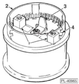
Fig. 1
INSTALLATION
Immediately after unpacking the disposer, check for possible shipping damage. If the disposer is found to be damaged, save the packaging material and contact the carrier within 15 days of delivery.
Prior to installation, test the electrical service to make sure that it agrees with the specifications on the disposer data plate.
Temporary support, such as blocking, must be provided for the disposer during installation to avoid excessive stress at welded or soldered cone to table connection.
ASSEMBLY
To attach the disposer assembly to the cone for a regular duty installation, see Fig. 2. Note the top clamp ring (1, Fig. 2) has drilled holes and the bottom clamp ring (3, Fig. 2) has threaded holes. Using five screws (2, Fig. 2) assemble rear halves of clamp rings to the back of the disposer flange (4, Fig. 2). Lift the disposer into position on the cone flange (5, Fig. 2) and assemble front halves of clamp rings using remaining five screws. Tighten all screws finger tight. Rotate disposer to desired position and tighten all screws evenly to form a water-tight joint.
To install accessory group E (sink adapter for 3-1/2" to 4" sink opening), use the short upper housing. See (2, Fig. 4) and the accessory group parts catalog.

Fig. 2

Fig. 3
PLUMBING CONNECTIONS
⚠ WARNING Plumbing connections must comply with applicable sanitary, safety, and plumbing codes.
Drain
The disposer is furnished with a 1-1/2" O.D. waste discharge spout suitable for connection to a standard trap. Install waste lines with the shortest possible run and best fall. The waste exit must not be higher than the center line of the waste outlet (1, Fig. 3 and 1, Fig. 4). Old waste lines must be thoroughly cleaned. Ream burrs from cut pipe ends and use fittings which will permit unrestricted flow. Drum traps and grease traps must NOT be used.
Water Connections
Connect disposer swirl (1, Fig. 5) from a 3/4" IPS cold water supply line. Install the five gallon per minute flow control supplied with the disposer (2, Fig. 5). If the water line pressure exceeds 60 psig, a pressure reducing valve (6, Fig. 5) (not

Fig. 4
supplied) should be installed. The minimum flow pressure for the disposer to function properly is 16 psig. Install a shut-off valve (not supplied) for proper servicing of the disposer.
All controls are supplied with a solenoid valve (4, Fig. 5) which must be installed in the water supply line as shown. Control Group 3 is furnished with a pressure switch which must be installed between the solenoid valve and pressure reducing valve.
Install a vacuum breaker (3, Fig. 5) according to the local plumbing codes. If local plumbing codes prohibit the use of a vacuum breaker, install an air gap water inlet (not supplied) observing the local codes.
ELECTRICAL CONNECTION
⚠ WARNING Electrical and grounding connections must comply with the applicable portions of the National Electrical Code and/or other local electrical codes.
⚠ WARNING Disconnect the electrical power to the machine and follow lockout/tagout procedures.
This unit must be connected to a dedicated, acceptable motor control switch with a marked OFF position to disconnect the appliance from all ungrounded supply conductors. The switch must be mounted within sight of the disposer or sink opening for the disposer.
Knockouts are provided in the motor junction box for making electrical connections to the unit. Flexible conduit should be used to permit moving the unit for periodic servicing and maintenance.
Select and follow wiring diagram, furnished with machine, applicable to your disposer and electrical service.
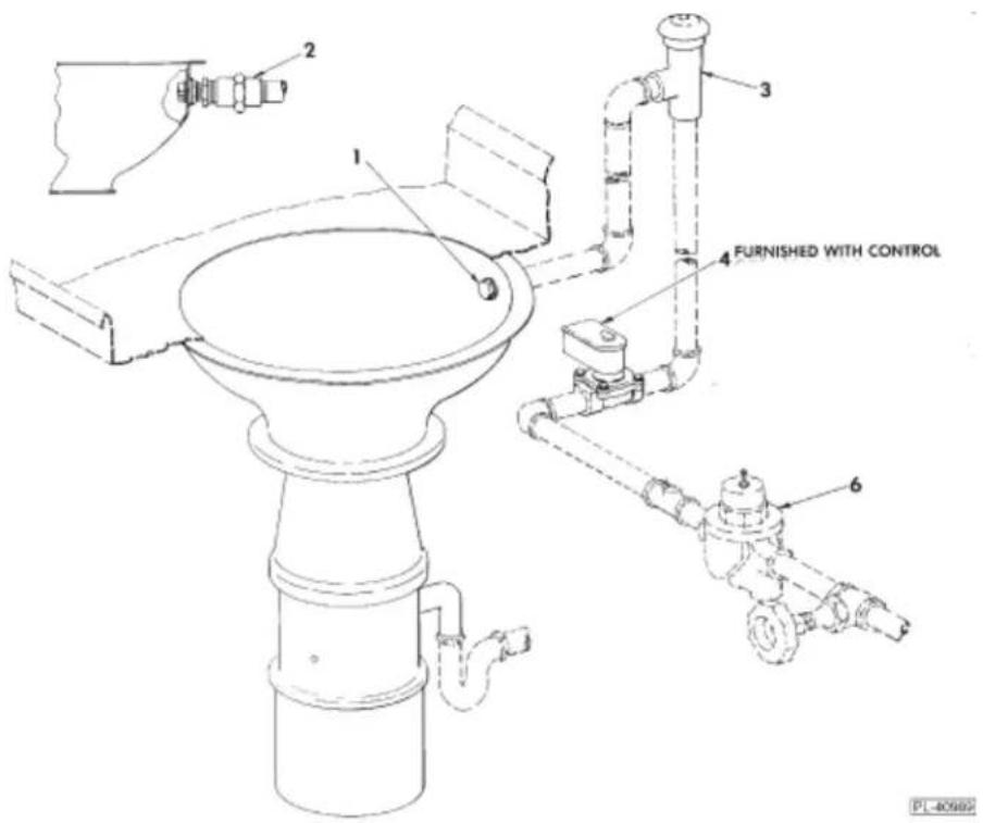
Fig. 5
OPERATION
Before operating disposer make sure it is clear of foreign objects such as metal or wire clippings, screws, nails, etc., which may have dropped into it during installation. Check the flywheel for free rotation.
⚠ WARNING Never use your hand to check rotation of flywheel or to remove foreign matter from the disposer. Use a stick or similar object to turn the flywheel. Foreign matter can be removed with tongs or pliers.
Start the disposer before feeding food waste. Be sure water is flowing. With typical optional controls, water flow and unit starting are simultaneous and automatic. Feed food waste into disposer. DO NOT feed china, metal, rags, clam shells, or similar material into the unit. DO NOT put grease or oil in the disposer. Oil or grease can clog the drain. Always allow the disposer to run for a short period after grinding is complete to assure proper flushing of the disposer and waste line. This flushing is automatically controlled with certain optional controls.
CONTROLS
WARNING Never reach inside this disposer while it is operating.
The operation of the disposer and additional available controls will depend on the selection of control devices. Refer to control group data sheet..
CLEANING
The food waste disposer should be kept in a clean and sanitary condition. Allow the disposer to run a few minutes after disposing of all food waste to completely flush out the interior. If food waste is allowed to accumulate due to improper clean-up, it will give off offensive odors. If this happens, cleaning can be accomplished by using a stiff brush with a strong soap and hot water solution. Light cleaning can be accomplished by grinding ice and a lemon through the disposer.
NOTICE Do not use chemical solvents or other drain cleaning compounds through the disposer.
MAINTENANCE
LUBRICATION
No lubrication is required for the food waste disposer. The disposer has grease packed sealed bearings requiring no service.
CUTTER BLOCKS
The cutter blocks (1, Fig. 1) may be rotated by a qualified Hobart Service Technician if the cutting edges become worn.
OVERLOAD PROTECTION
The disposer motor is protected by a thermal, resetable overload protector and will trip if the motor is overloaded. To reset, allow approximately five minutes for cooling, then press the manual reset button located on the motor shell opposite the motor junction box. An arrow on the motor shell indicates location of the button. Restart the disposer using normal operating procedure. If overload protector continues to trip, contact your local Hobart Service Office.
NOTES


- FOOD WASTE DISPOSERS
- INSTRUCTION
- TABLE OF CONTENTS
- Installation, Operation and Care of MODELS FD4-50, FD4-75, & FD4-125 FOOD WASTE DISPOSERS
- SAFETY
- RECOGNIZE SAFETY INFORMATION
- READ ALL INSTRUCTIONS
- KEEP OUT OF REACH OF CHILDREN
- DO NOT OPERATE IF DAMAGED.
- DO NOT LEAVE DISPOSER UNATTENDED.
- GENERAL
- INSTALLATION
- ASSEMBLY
- PLUMBING CONNECTIONS
- Drain
- Water Connections
- ELECTRICAL CONNECTION
- OPERATION
- CONTROLS
- CLEANING
- MAINTENANCE
- LUBRICATION
- CUTTER BLOCKS
- OVERLOAD PROTECTION
- NOTES
Brand : Hobart
Model : FD4-75
Category : Bin