Z2040 LP-VCF - Synthesizer Tiptop Audio - Free user manual and instructions
Find the device manual for free Z2040 LP-VCF Tiptop Audio in PDF.


| Product Type | Eurorack synthesizer module – 4-pole voltage-controlled low-pass filter (VCF) |
| Model | Z2040 LP-VCF |
| Brand | Tiptop Audio |
| Main Function | Voltage-controlled low-pass filter with configurable VCA, resonance compensation, and frequency modulation capabilities |
| Filter Type | 24 dB/oct low-pass (4-pole) |
| VCA Configuration | Selectable via jumpers: VCA disabled, VCA at input, VCA at output |
| Gain Knob Range | MIN (below 0 dB) for sweet SSM2040-like sound; 0 dB with resonance compensation; MAX for non-linear clipping (up to 21 Vp-p output) |
| VC-FM (Voltage Controlled Frequency Modulation) | VCA on FM line allows modulation of FM depth by external CV |
| Self-Oscillation | Yes – produces a pure sine wave with resonance at maximum (tracks ~7 octaves with calibration) |
| Input Impedance (Resonance CV) | 10 kΩ |
| Input Impedance (FM CV) | 220 kΩ |
| Input Impedance (VC-FM CV) | 22 kΩ |
| Input Impedance (Gain CV) | 30 kΩ |
| CV Input Range | ±2.5 V typical (not limited, can exceed) |
| Power Supply | ±12 V or ±15 V (Eurorack standard) |
| Dimensions | Typical Eurorack module: 10 HP wide, 3U height (exact dimensions not specified in manual) |
| Manufacturing | Made in the USA |
| Designer | Gur Milstein |
| User Manual Pages | 10 pages (available in PDF) |
| Special Features | Resonance-gain compensation, configurable VCA, VC-FM with VCA, high-output clipping for driving other modules |
Frequently Asked Questions - Z2040 LP-VCF Tiptop Audio
User questions about Z2040 LP-VCF Tiptop Audio
0 question about this device. Answer the ones you know or ask your own.
Ask a new question about this device
Download the instructions for your Synthesizer in PDF format for free! Find your manual Z2040 LP-VCF - Tiptop Audio and take your electronic device back in hand. On this page are published all the documents necessary for the use of your device. Z2040 LP-VCF by Tiptop Audio.
USER MANUAL Z2040 LP-VCF Tiptop Audio
V.2 / single pcb Gray Panel
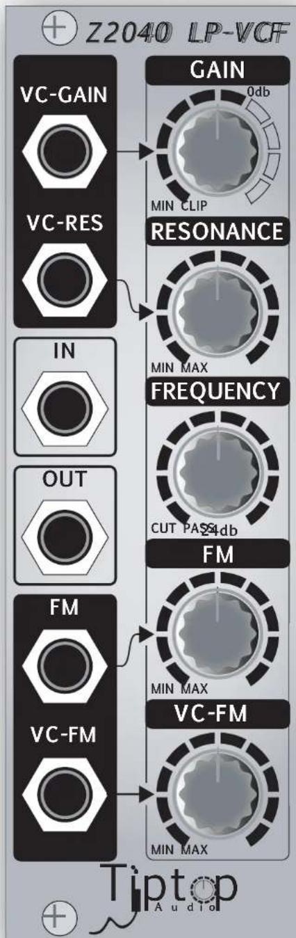
Z2040-VC-Filter
Design - Gur Milstein
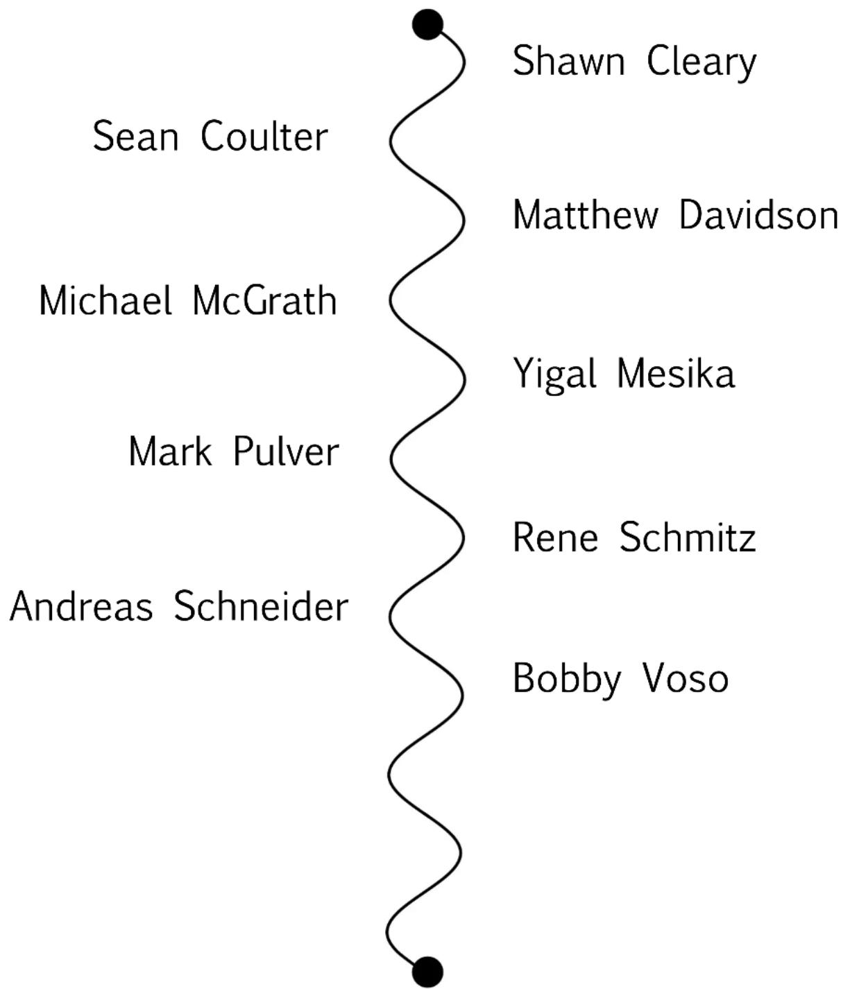
Special Thanks
flowchart
graph TD
    A["Sean Coulter"] --> B["Shawn Cleary"]
    C["Michael McGrath"] --> D["Matthew Davidson"]
    E["Mark Pulver"] --> F["Yigal Mesika"]
    G["Andreas Schneider"] --> H["Rene Schmitz"]
    I["Bobby Voso"] --> J["Bobby Voso"]
MADE IN THE USA
Tiptop Audio 2009 All Rights Reserved
Welcome.
This quick start guide provides an introduction to the operation of the Z2040 VC-Filter. The Z2040 4-Pole VCF is an enhanced version of the famous SSM2040 filter chip. Both the Z2040 and the SSM2040 are based on a discrete circuit design covered by a US patent assigned to Oberheim Electronics in the 70's. Although the Z2040 is inspired by this design, the Z2040 is not designed to be an exact reproduction of the SSM2040 sound. The Z2040 significantly extends the capabilities of this vintage sound.
In this manual we will go over the additional features and characteristics of the Z2040.
Understanding the Gain knob and the configurable VCA:
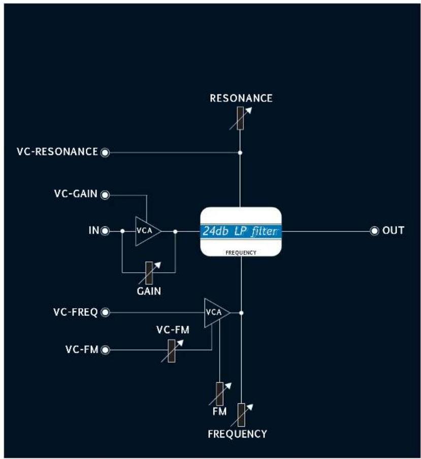
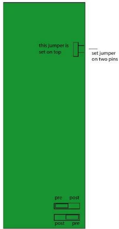
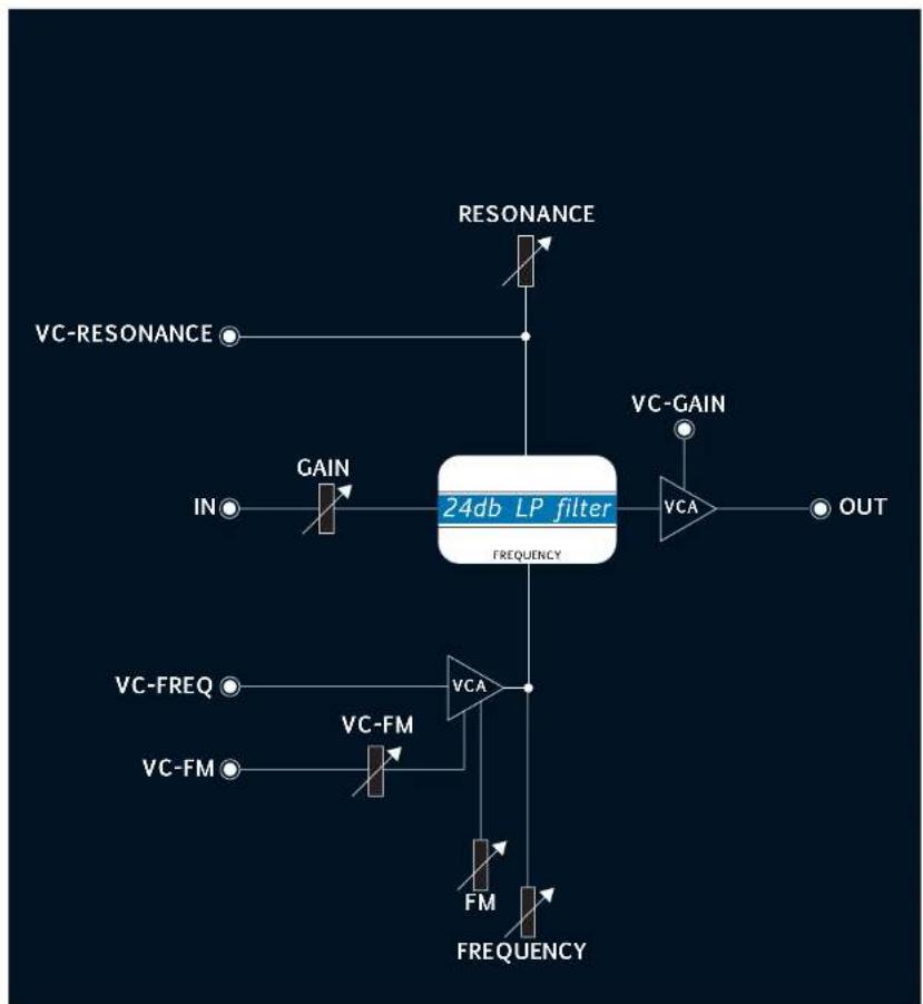
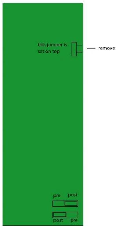
The Z2040 provides an Audio VCA that can be configured at either the Input or the Output of the Filter. The Z2040 comes with the VCA configured at the Input. On the green printed circuit board are three headers which are used to configure the VCA position. Here are the three configuration:
1 ) VCA disable: Remove TOP jumper.
2) Input VCA: (see Fig. A)
3 ) Output VCA : (see Fig. B)
(cont. on pg.4)
flowchart
graph TD
    A["VC-RESONANCE"] --> B["VCA"]
    C["VC-GAIN"] --> B
    D["IN"] --> B
    E["VA"] --> B
    F["GAIN"] --> B
    G["VC-FREQ"] --> H["VCA"]
    I["VC-FM"] --> H
    J["FM"] --> K["FREQUENCY"]
    L["RESONANCE"] --> M["24db LP filter"]
    N["OUT"] --> M
    B --> M
    H --> M
    H --> N
Fig. A
flowchart
graph TD
    A["IN"] --> B["GAIN"]
    B --> C["24db LP filter"]
    C --> D["VCA"]
    D --> E["OUT"]
    F["VC-FREQ"] --> G["VC-FM"]
    H["VC-FM"] --> I["VC-FM"]
    J["FC"] --> K["FM"]
    L["FREQUENCY"] --> M["FREQUENCY"]
    N["VC-RESONANCE"] --> O["RESONANCE"]
    P["VC-GAIN"] --> Q["VCA"]
Fig. B
(cont. on pg.5)
Please Note: When the VCA is configured to filter output it will block the sound, only by applying a CV to the VC-Gain input will it open the VCA for sound to pass through.
The front panel Gain knob functions totally independent of the VCA and only sets the input Gain regardless of the VCA position (VCA on Input or output). When the VCA is configured to the Input then the audio from the VCA and from the Gain Knob are mixed together. When the VCA is configured at the output the gain knob affects only the input, the idea behind that is to, the idea behind that is to maintain control of the Input Gain even if the VCA is set to the Output.
Understanding the Z2040's unique gain stage:
The following describes the behavior of the Z2040 at three different positions of the Gain knob:
MIN - just before 0db:
In this range the Z2040 will sound and behave similarly to the SSM2040 filter chip. The ratio between resonance and input signal is set in a similar way to that of the original SSM2040. This means the Input signal's volume will drop when Resonance is increased. This range has a low distortion and will reproduce the “sweet” sound of the SSM2040.
0db:
In this spot the unique resonance-gain-compensation circuit will kick in, providing a gain compensation of the input signal as the Resonance is increased. This gain compensation loop dramatically reduces the drop in volume of the input signal when the Resonance is increased, in turn, producing resonating sounds with additional “punch.”
Just past 0db - MAX:
This range causes the Z2040 to behave in a non-linear fashion which can result in some very interesting sonic results.
In this range any sound wave with a magnitude of 10Vp.p (Z3000 waveforms, for example) will be clipped by the filter core. This clipping will get deeper as gain is increased. This kind of filter core clipping is soft and smooth and will add harmonics to the incoming sound.
When the Resonance is increased in this range the output gain (volume) will increase as well, and at maximum settings will output a signal of up to 21Vp.p!!. This special feature is inherent from the structure of the resonance-gain-compensation and will cause the Output to add additional clipping and distortion to the filtered signal and the resonance sine shape. The Output signal amplification adds a 'hard' sound clipping by driving the Output Op Amps to their rails. This high gain could also prove useful to drive other modules following the Z2040 in the signal flow to make them distort and clip the signal even further.
Understanding the VC-FM:
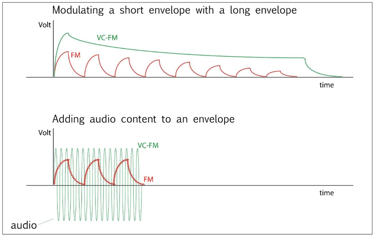
Most VC-filters have a CV input to sweep/modulate the cut-off frequency, in the Z2040's case this input is labeled FM (Frequency Modulation). The Z2040 adds a unique feature providing the ability to modulate the magnitude of the FM signal by another signal, this is done by placing a VCA on the FM line. This simple yet effective structure provides a variety of modulation tricks. The most common use will be to modulate the magnitude of an Envelope or an LFO with another Envelope and/or LFO. On the other hand, modulating the FM signal using Audio waveforms will add harmonic content to the FM signal. (see fig. C)
line
| Time | VC-FM Volt | FM Volt | |------|------------|---------| | 0 | 0 | 0 | | 1 | ~0.8 | ~0.6 | | 2 | ~0.7 | ~0.5 | | 3 | ~0.6 | ~0.4 | | 4 | ~0.5 | ~0.3 | | 5 | ~0.4 | ~0.2 | | 6 | ~0.3 | ~0.1 | | 7 | ~0.2 | ~0.05 | | 8 | ~0.1 | ~0.02 | | 9 | ~0.05 | ~0.01 | | 10 | ~0.02 | ~0.005 | | 11 | ~0.01 | ~0.002 | | 12 | ~0.005 | ~0.001 | | 13 | ~0.002 | ~0.0005 | | 14 | ~0.001 | ~0.0002 | | 15 | ~0.0005 | ~0.0001 | | 16 | ~0.0002 | ~0.00005| | 17 | ~0.0001 | ~0.00002| | 18 | ~0.00005 | ~0.00001| | 19 | ~0.00002 | ~0.000005| | 20 | ~0.0 | ~0 |Fig. C
Self Oscillating:
The Z2040 can be used as a pure Sine wave Voltage Controlled Oscillator. With no signal on the input and the Resonance knob at maximum the Z2040 will oscillate a very low distortion sine wave. Although the Z2040 does not provide an exponential 1V/Oct input, the Z2040 will track precisely over about 7 Octaves using MOTU Volta calibration. Modulating the VC-Resonance and/or the FM inputs in self oscillation will transform the sine wave and add harmonics.
Specification:
Resonance / VC-RES:
The Resonance knob sets an offset to the VC-RES.
Input impedance = 10K Ohm
Input range: +/-2.5V*
FM / FM-IN:
The FM knobs attenuates the FM-IN
Input impedance = 220K Ohm
Input Range: +/-2.5V*
VC-FM / VC-FM IN
The VC-FM knob attenuates the VC-FM IN
Input impedance: 22K Ohm
Input Range: +/-2.5V*
Gain / VC-Gain
Gain knob sets the input gain to the filter regardless of the VCA position.
Input impedance: 30K Ohm
Input Range: +5V*
* Input range is not limited and can exceed these values
Impedance:
* Powering the Z2040 from +/-15V is supported, some slight variation in control range may occur.
Enjoy, make music.


Brand : Tiptop Audio
Model : Z2040 LP-VCF
Category : Synthesizer