
iQ2001 Gen II - Water heater Intellihot - Free user manual and instructions
Find the device manual for free iQ2001 Gen II Intellihot in PDF.


| Brand | Intellihot |
| Model | iQ2001 Gen II |
| Product Type | Commercial Tankless Water Heater |
| Dimensions (H x W x D) | 30.5 x 19.7 x 15.7 inches (775 x 500 x 400 mm) |
| Weight | 110 lbs (50 kg) |
| Power Supply | 240V AC, 60 Hz, 3-phase |
| Maximum Input Power | 99 kW (337,000 BTU/h) |
| Flow Rate | 8.6 GPM (32.5 L/min) at 77°F rise |
| Energy Source | Natural Gas or Propane |
| Efficiency | Up to 96% thermal efficiency |
| Ignition | Direct spark electronic ignition |
| Venting | Stainless steel, category III venting |
| Control Interface | Digital display with remote control capability |
| Safety Features | Flame sense, overheat protection, freeze protection, and water flow sensor |
| Maintenance | Annual descaling recommended; accessible inlet filter |
| Warranty | Limited 10 years on heat exchanger, 2 years on parts |
| Certifications | ANSI Z21.10.3 / CSA 4.3, low NOx |
Frequently Asked Questions - iQ2001 Gen II Intellihot
User questions about iQ2001 Gen II Intellihot
0 question about this device. Answer the ones you know or ask your own.
Ask a new question about this device
Download the instructions for your Water heater in PDF format for free! Find your manual iQ2001 Gen II - Intellihot and take your electronic device back in hand. On this page are published all the documents necessary for the use of your device. iQ2001 Gen II by Intellihot.
USER MANUAL iQ2001 Gen II Intellihot
the information in these instructions is no, followed exactly, a line or explosion could result causing property damage, personnel injury, or death.
— Do not store or use gasoline other flammable vapors and liquids in the vicinity of this or any other appliance.
WHAT TO DO IF YOU SMELL GAS
- Do not try to light any appliance
- Is not touch any electrical switch; do not use any phone in your building.
immediately on your gas supplier from a neighbor's phone. Follow the gas supplier's instructions.
If you cannot reach your use supplier, call the fire department.
Installation and service must be performed by a qualified installer, service agency, or the gas supplier.
AVERTISSEMENT
Operation & Installation Manual
iQ2001, Gen II iQ3001, Gen II


Intellihot
Thank you for purchasing this Intellihot unit,

Our journey to create a better heating system began back in the winter of 2005, when a tank-type water heater broke down and flooded my basement. By combining the principles of a diesel engine's robustness, robotics intelligence, and marine environment durability, we set out to design a unit from the ground up –that would outperform and outlast all others. Quickly, our goal grew from not just making a better water heater, but creating an efficient and intelligent water heating and delivery system.
Innovation is our hallmark and simplicity, efficiency, and durability are at the core of every Intellihot product. Our water heaters utilize the best attributes of tank and tankless – with intelligent logic and integrated recirculation. The result is a water heating system capable of handling the extreme loads of commercial applications with the preciseness needed for residential applications.
Our products are proudly engineered and built in Galesburg, Illinois making Intellihot the first and only US based manufacturer of gas fired condensing tankless water heating systems. Over the past eight years Intellihot has helped commercial customers throughout the nation save thousands of dollars while eliminating downtime. As we continue to expand our coverage across North America, we strive to provide you with the same unmatched performance advantages and savings. Our talented team of dedicated professionals is ready to assist you and help your business succeed.
I thank you for purchasing our Intellihot products.
Sincerely,
Sridhar Deivasigamani
President, Intellihot Inc.


Table of Contents
1. General Information
1.1 Items Shipped With Water Heater ..... 5
1.2 Serial Number Locations....5
2. Safety
2.1 Safety Signal Words....6
2.2 Installation Warnings 6
3. Technical Specifications
3.1 Specifications Chart 8
3.2 High Elevation Installations ..... 8
3.3 Clearance Requirements 9
3.4 Connection Specifications 9
3.5 Exhaust Gas Standards ..... 9
3.6 Overall Dimensions.... 10
3.7 Configuration Options 12
4. Quick Reference Installation Guide
4.1 Install the Water Heater.... 13
4.2 Pre-Startup Instructions 13
5. Preparation Before Installation
5.1 Selecting an Indoor Installation Site ..... 15
5.2 Selecting an Outdoor Installation Site ..... 16
6. Gas Connection
6.1 Quick Reference Installation Instructions .... 17
6.2 Fuel Source 17
6.3 Gas Pressure Requirements ..... 17
6.4 Gas Pressure Regulator....17 6.4.1 Venting of Gas Supply Regulators....17
6.5 Length of Gas Supply Line.... 18
6.6 Gas Piping Material 18
6.7 Determine Correct Gas Pipe Diameter ..... 18
6.8 Gas Pipe Drip Leg and Shut-off Valve ..... 18
6.9 Connecting Gas Line to Unit 18
6.10 Gas Pipe Sizing Tables 20
7. Air Intake Inlet and Exhaust Gas Outlet Pipe Connections
7.1 Quick Reference Installation Guide ..... 22
7.2 Typical Single Unit Air Intake Inlet and Exhaust Gas Outlet Pipe Installation.....22
7.3 Two Pipe Vent System (Direct Vent) ..... 24
7.3.1 Single Unit Configurations ..... 24
7.3.2 Multiple Units Configurations ..... 24
7.3.3 Side Wall Air Intake Inlet and Exhaust Gas Outlet Pipe Termination ..... 25
7.3.4 Roof Air Intake Inlet and Exhaust Gas Outlet Pipe Termination ..... 25
7.4 Single Pipe Venting System (Power Vent) .. 26
7.4.1 Single Unit 26
7.4.2 Multiple Units 26
7.5 Combustion Air Requirements....27
7.6 Intake Air Inlet and Exhaust Gas Outlet Pipe Diameter and Length....27
7.7 Venting Clearance Specifications ..... 28
7.8 Exhaust Gas Outlet Pipe Materials ..... 29
7.9 Air Intake Inlet Pipe Vent Materials ..... 30
7.10 Recommended Exhaust Gas Outlet Pipe Transitions....30
8. Water Connections
8.1 Quick Reference Installation Instructions ... 31
8.2 Hot Water Connection.... 31
8.3 Cold Water Connection 32
8.4 Condensate Drain Line 33
9. Electrical Power
9.1 Electrical Recommendations 35
9.2 Connection Instructions....35
10. Adjusting CO2 Level
10.1 General Information 36
10.2 Adjustment Procedure 36
11. Natural Gas to Propane Conversion
11.1 General Information 40
11.2 Conversion Procedure 40
12. Operation
12.1 Control Panel....42
12.2 Turning Water Heater ON and OFF ..... 42
12.3 Setting the Time 43
12.4 Adjusting the Water Temperature ..... 44
12.5 Security 44
12.5.1 Setting Passcode Protection ..... 44
12.5.2 Changing Passcode....45
12.5.3 Forgot Passcode 46
12.6 iNTouch 46
12.7 Life Screen 47
12.8 Unit Information 48
12.9 More Screens 49
12.9.1 Wi-Fi 49
12.9.2 Error History 50
12.9.3 telliCare Service
(Subscribe at Startup) 51
13. Connecting Multiple Units
13.1 General Information 53
13.2 Installation Procedure....53
13.2.1 telliCare for Multiple Units ..... 54
14. Maintenance
14.1 Air Filter....55
14.1.1 Inspection 55
14.1.2 Cleaning Procedure....55
14.2 Maintenance-Free Circulation Pumps ..... 55
14.3 Heat Engine Locations 56
15. Wiring Diagrams and Troubleshooting
15.1 Operational Flow Chart.... 57
15.2 Complete Wiring Diagram (all models) ..... 58
15.3 Control Board Wiring Diagram (iQ2001)....59
15.4 Control Board Wiring Diagram (iQ3001) ... 60
15.5 Troubleshooting Guide 61
16. Requirements for State of Massachusetts
16.1 Notice Before Installation....66
17. Warranty
17.1 Warranty 67
18. Product Warranty
18.1 Warranty 70

WARNING
If the information in these instructions is not followed exactly, a fire or explosion could result causing property damage, personal injury, or death.
— Do not store or use gasoline or other flammable vapors and liquids in the vicinity of this or any other appliance.
WHAT TO DO IF YOU SMELL GAS
- Do not try to light any appliance.
- Do not touch any electrical switch; do not use any phone in your building.
- Immediately call your gas supplier from a neighbor's phone. Follow the gas supplier's instructions.
- If you cannot reach your gas supplier, call the fire department.
— Installation and service must be performed by a qualified installer, service agency, or the gas supplier.

AVERTISSEMENT
This product complies with ANSIZ21.10.3 (2011) / CSA 4.3 Gas Water Heater. For use as potable water heating.




- iQ2001 Only

DANGER

To avoid product damage, personal injury, or even possible death, carefully read, understand, and follow all the instructions in this Operation and Installation manual before installing this. Improper installation, adjustment, alteration, tenance can cause injury, loss of life, and/or damage. This water heater should be installed serviced by a qualified technician. The lack of service can result in a dangerous condition.
Due to Intellihot's policy of continuous product improvement and technology, the design and/or technical specifications in this manual are subject to change without notice.
This manual contains safety information, installation instructions, and maintenance procedures. It must be left with the homeowner or placed near the water heater in a noncombustible location. The customer should retain this manual for future reference.
Contact Information
Call us, your dealer, first if you have any questions about this product. We can help answer questions about installation, operation, or if there are damaged or missing parts when unpacking this unit from the shipping box.
Dealer Contact Information
1. General Information
1.1 Items Shipped With Water Heater
The shown in the illustration are shipped loose with the water heater.
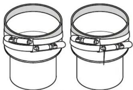
Adapter (Polypropelene to PVC or CPVC)
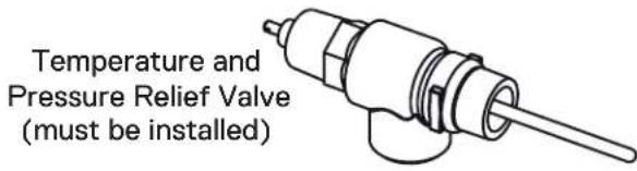

Strainer (must be installed)


Keys

1.2 Serial Number Locations
The unit's serial number is located on the rating plate on the rear panel of the unit. Please provide this serial number when inquiring about service or warranty solutions. Each heat engine, up to twelve depending on model, also has a serial number located on its ASME certification tag.
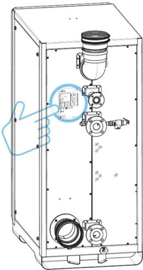
Unit Serial Number: ____
Heat Engine 1 (ASME) Serial Number: ____
Heat Engine 2 (ASME) Serial Number: ____
Heat Engine 3 (ASME) Serial Number: ____
Heat Engine 4 (ASME) Serial Number: ____
Heat Engine 5 (ASME) Serial Number: ____
Heat Engine 6 (ASME) Serial Number: ____
Heat Engine 7 (ASME) Serial Number: ____
Heat Engine 8 (ASME) Serial Number: ____
Heat Engine 9 (ASME) Serial Number:
Heat Engine 10 (ASME) Serial Number: ____
Heat Engine 11 (ASME) Serial Number: ____
Heat Engine 12 (ASME) Serial Number: ____
Date of Installation: ____ / ____ / ____
2. Safety
2.1 Safety Signal Words
! DANGER
Indicates an imminently hazardous situation which, if not avoided, will result in death or serious injury. This signal word is limited to the most extreme situations.
WARNING
Indicates a potentially hazardous situation which, if not avoided, could result in death or serious injury.
CAUTION
Indicates a potentially hazardous situation which, if not avoided, may result in minor or moderate injury.
NOTICE
Indicates that equipment or property damage can result if instructions are not followed.
SAFETY INSTRUCTIONS
Safety instructions (or equivalent) signs indicate specific safety-related instructions or procedures.
Note: Contains additional information important to a procedure.
2.2 Installation Warnings
WARNING
DO NOT use this water heater for any purpose other than water heating.
Read, understand, and follow the Installation and Operation manuals, including all warnings and precautions, before operating this water heater. If you do not follow these instructions exactly, a fire or explosion may result, causing property damage, personal injury, or loss of life.
Follow all local codes and the most recent edition of the National Fuel Gas Code (ANSI Z223.1/NFPA 54) in the USA or the Natural Gas and Propane Installation Code in Canada (CSA B149.1).
This water heater must be installed by a licensed plumber, gas fitter, and/or professional service technician. Installation by unqualified person(s) voids the warranty.
Designed for operations at outlet temperature(s) not in excess of 190° F ( 88° C).
! DANGER
A. This water heater does not have a pilot. It is equipped with an ignition device which automatically lights the burner. Do not try to light the burner manually.
B. BEFORE OPERATING, smell all around the water heater area for gas. Be sure to smell next to the floor because some gas is heavier than air and will settle on the floor.
WHAT TO DO IF YOU SMELL GAS:
• Do not try to light any appliance.
- Do not touch any electric switch; do not use any phone in your building.
- Immediately call your gas supplier from a neighbor's phone. Follow the gas supplier's instructions.
- If you cannot reach your gas supplier, call the fire or police department.
C. Use only your hand to turn the manual gas shut-off valve. Never use tools. If manual gas shut-off valve will not turn by hand, don't try to repair it. Call a qualified service technician. Force or attempted repair may result in a fire or explosion.
WARNING
DO NOT use or store flammable liquids around the water heater, including gasoline, oils, spray paints, etc.
DO NOT operate this water heater unless it is properly vented to the outside (the exhaust vent piping must be connected from the unit directly to the outside). Improper venting can cause a build-up of carbon monoxide, which can result in brain damage or death. Exhaust gases must be completely expelled out of the building.
This water heater is factory preset for NATURAL GAS but may be field converted for use with propane. For propane conversion, refer to the Propane (LPG) Conversion section of this manual. Connecting the water heater to any other gas supply can result in property damage, serious injury, or even death.
This water heater is suitable for use in potable water heating applications. The cold and hot water fittings on the top of the water heater MUST NOT be connected to any heating system.
The water heater temperature is factory set to 120°F (49°C). Hot water temperatures above 125°F can cause severe burns instantly or death from scalds. If the proposed water heater outlet temperature is to be set above 125°F, installation of a thermostatically controlled (or temperature limiting) mixing valve is recommended for all hot water going to faucets to avoid the risk of scalding. Examples include commercial applications where 140°F (60°C) is often needed or if the space heating temperature required is higher than the domestic hot water. Always check the temperature of the hot water before bathing, showering, washing, etc.
Protect against snow and debris accumulation around the vent terminations. Regularly inspect the exhaust vent pipe and the air intake pipe to ensure they remain clear from obstructions at all times.

CAUTION
Make sure you know the location of the gas shut-off valve and how to operate it. Immediately close the gas shut-off valve if the water heater is subjected to fire, overheating, flood, physical damage, or any other damaging condition that might affect the operation of the unit. Have the water heater checked by a qualified technician before resuming operation.
If the water quality is known to have high acidity and/or high hardness, water treatment is recommended. Consult the local water authority.
SAFETY
INSTRUCTIONS
DO NOT use this appliance if any part has been under water.
DO NOT reverse the cold water and gas connections as this will damage the gas valve.
DO NOT overtighten fittings as damage may occur, causing internal leakage.
The appliance should be located in an area where leakage within the unit or at its connections will not result in damage to the surrounding area. The manufacturer will not be responsible for any damage resulting from leaking if adequate drainage is not provided.
3. Technical Specifications
3.1 Specifications Chart
| Characteristic | Models | |
| iQ2001, Gen II iQ3001, Gen II | ||
| Type Indoor/Outdoor, floor | Mounted | |
| Fuel | Preset for natural gas; Conversion to propane possible without additional parts | |
| Minimum value BTU/h gross 30,000 | ||
| Maximum value gross BTU/h 1,999,999 3,001,000 | ||
| Maximum BTU/h net value 1,860,000 2,790,930 | ||
| Thermal Efficiency 93% 93% | ||
| Variation ratio 66:1 100:1 | ||
| Water supply / hot water connections produced | 3" manifold with 7.5" DE flange | |
| Gas supply connection | 2" manifold with 6" DE flange | |
| Condensate drain connection | 3/4" PVC | |
| Maximum condensate flow rate (GPM) | 14,4 | 21,6 |
| Dimensions Height x Width x Depth (inches) | 67,7 X 30 X 60,4 (66 pi3) | 67,7 X 30 X 60,4 (66pi3) |
| Clearances for maintenance purposes | 24" on all sides, 32" front (maintenance) | |
| Weight (lb) | 1225 | 1645 |
| Type of air intake / exhaust gas | Sealed combustion (2 ducts: air intake and gas evacuation). Ambient air combustion (1 duct: exhaust gases only) | |
| Exhaust duct/intake materials (U.S.) | PVC nomenclature 40 PVCC nomenclature 40, polypropylene, stainless steel | |
| Exhaust duct / intake materials (Canada) | Category BH chimney: IIA (PVC), II B (PVCC), II C (polypropylene), I (stainless steel AL294C) | |
| Diameter of exhaust ducts / air intake | 8" ∅ | |
| Max duct length of 6" - Ambient air filling (one duct) | 155 ft | 40 ft |
| Max duct length of 6" - Sealed combustion (two ducts) | 75 ft* | 20 ft* |
| * Note: Subtract 5' per elbow at 90° and 2' per elbow at 45° from the maximum length indicated above. | ||
| Ignition | Electronic spark ignition | |
| Temperature range | 100°F - 190°F | |
| Temperature stability | +/- 4°F | |
| Ambient temperature of the installation location | 40°F - 130°F | |
| Security | Amme detection electrode, thermal fuse, overheat prevention device, speed monitoring device souante, chimney temperature monitoring device, chimney obstruction detector, two amme sensors | |
| Minimum/Maximum Water Pressure (PSIG) | 30 / 160 | |
| NG/LPG - minimum static gas pressure (full throttle) | 2.5 in. EC . (non-corrugated black iron) | |
| NG/LPG - maximum static gas pressure | 14" CE | |
| Gas pressure to make adjustments | 8" EC for natural gas, 11" EC for propane | |
| Electrical components | (2) AC 120 V, 60 Hz | |
| Power consumption | (2) max 120 A, 64 W (Sleep) | (2) Max 30 A, 96 W (Sleep) |
| Internal water volume (gallons) | 3 | 6 |
| Features and approvals | iQ2001, Gen II | iQ3001, Gen II |
| Built-in redundancy | Multiple heat exchangers with individual control devices | |
| Waterfall | Masterless, 3 devices, automatic rotation | Sams master, 2 devices, auto-rotate |
| Common air Intake duct/evac. gas | Yes, max. 3 devices | Yes, max. 2 devices |
| Exchanger | 316L stainless steel, expandable | |
| ANSI Z21.10.3 Approval | ETL | |
| SCAQMD | Ultra-low NOx emissions (below 20 ppm) | |
| ASME | HLW | |
| MDM Performance | iQ2001, Gen II | iQ3001, Gen II |
| Hot water produced, 45°F rise | 83.0 | 124.5 |
| Hot water produced, 70°F rise | 53.4 | 80.1 |
| Hot water produced, 90°F rise | 41.5 | 62.3 |
| Hot water produced, 100°F rise | 37.4 | 56.0 |
| Hot water produced, 140°F rise | 26.7 | 40.0 |
| Guarantee | Heat exchanger: 10 years; All other rooms: 2 years | |
| Note: As the product is constantly being improved, changes can be made to the design and specifications at any time. | ||
3.2 High Elevation Installations
For operation at elevations above 2,000 feet, the hot water delivery capacity should be reduced by 4% for each 1,000 feet above sea level.
3.3 Clearance Requirements
In order for the water heater to operate properly and efficiently, the clearances specified in the table below are recommended.
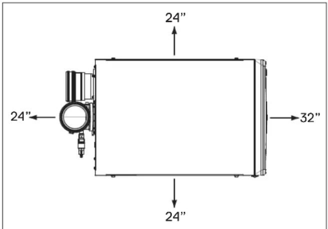
Service Clearances. If multiple units are installed, the side clearance can be shared between the two units.
| Location R | Required Recommended | ||
| From Combustibles | From Non-Combustibles | Service Clearance 1 | |
| Top 6" (15.2 | cm) 2" (50.8 cm) | 13" (46 cm) | |
| Back 5/8" | (15.8 mm) 5/8" (15.8 mm) | 24" (61 cm) | |
| Sides 1" (25 | .4 mm) 1/2" (12.7 mm) | 24" (61 cm) | |
| Front | 2" (5.1 cm) | 2" (5.1 cm) | 32" (81 cm) |
| Bottom 0" | (0 mm) 0" | (0 mm) 0" | (0 mm) |
1 Service clearances are recommended dimensions to allow for normal service of the unit.
3.4 Connection Specifications
| Connections | |
| Description | Specification2 |
| Gas Supply Inlet Connection | 2” NPT Flange Connection |
| Water Supply Inlet Connection | 3” Copper Flange Connection |
| Heated Water Outlet Connection | 3” Copper Flange Connection |
| Exhaust Gas Vent1 | 8” Polypropylene |
| Air Intake Inlet1 | 8” Polypropylene |
| Condensate Drain Connection | 3/4” |
| Power Supply | 120V AC Power (2 Circuits) |
1 Use the 8" adapter provided when using PVC or CPVC pipe.
2 Using sizes other than specified can cause damage to the water heater and will void the warranty.
3.5 Exhaust Gas Standards
| CO2and CO Standards | ||
| Description | CO2Range (%) | Max. CO Level (ppm) |
| Natural Gas | ||
| High Fire | 9.1% to 9.3% | < 200 ppm |
| Low Fire | 9.1% to 9.3% | < 60 ppm |
| Propane Gas | ||
| High Fire | 10.1% to 10.5% | < 200 ppm |
| Low Fire | 10.1% to 10.5% | < 60 ppm |
3.6 Overall Dimensions
![30.0 [762] FRONT DISPLAY FRONT PANEL 64.0 [1825] Intellihot 3.7 [85] 9.3 [235] FORK-LIFT CHANNELS](/content/2026/05/955810/images/f8c596a26546797dcf49e129e7a8485a9a27f7269040c8affc9a482bfce122dc.jpg)
FRONT VIEW
![67.0 [1701] 60.4 [1635] REMOVABLE SIDE PANLES 66.7 [1695] 66.5 [1690]](/content/2026/05/955810/images/fac511c85c164b2fd9a35913d09933df33fea03071d12ab9993aef3b9eed36ca.jpg)
SIDE VIEW
![iQ3001 REMOVABLE PANEL 15.0 [381] 8" PVC OR PP EXHAUST (90° ELBOW NOT SHOWN) 2" GAS INLET 6" OD FLANGE 3" WATER OUTLET 7-1/2 OD FLANGE 3" WATER INLET 7-1/2 OD FLANGE 8" PVC OR PP AIR INTAKE FILTERED 1" NPT CONDENSATE DRAIN 4.9 [126] 60.5 [1537] 52.8 [1342] 43.6 [1108] 20.4 [519] 12.1 [308] 6.7 [170]…](/content/2026/05/955810/images/083440c8ddf4485ec8f2aa2592ed4c2746d7c054f1164c7244c3290815f5f858.jpg)
REAR VIEW
![19.7 [500] 5.2 [131] 4.0 [102] 24.7 [628] 24.7 [628] Ø.6 [16]](/content/2026/05/955810/images/d35bc23725cd87b10429247024212bda02c15f42d023180a1f83f94fe5c32dfc.jpg)
BOTTOM VIEW
3.7 Configuration Options
![graph TD A["Cold Water Supply"] --> B["Expansion Tank"] C["Gas Supply"] --> B B --> D["Hot Water Supply"] D --> E["Hot Water Fixtures"] E --> F["Recirculation Line"] F --> G["Hot Water Return"] G --> H["Reccirculation Line"] H --> I["Hot Water Supply"]](/content/2026/05/955810/images/55347eaff1414ead556f410883e92feb7eebcb783ee68a602959f2d7ee5e5f1a.jpg)
System with no storage tank and without mixing valve.
![graph TD A["Cold Water Supply"] --> B["Expansion Tank"] C["Gas Supply"] --> B B --> D["Recirculation Line"] D --> E["Low Temp Return"] E --> F["Low Temp FIXTURES"] E --> G["High Temp FIXTURES"] G --> H["Hot Water Supply"] H --> I["Thermostatic Mixing Valve (Installed per MFG instructions)"] I --> J[…](/content/2026/05/955810/images/d4d38aba6dcbdbf18d815f1eebd564b36f70c9db35f2c8101a9d9a12083146bc.jpg)
Multiple unit system with mixing valve but no storage tank.
4. Quick Reference Installation Guide
4.1 Install the Water Heater
When installing the water heater, follow all local building codes and the current edition of the National Fuel Gas Code (ANSI Z223.1/NFPA 54) in the USA, or National Gas and Propane Installation Code (CAN/CGA B149.1) in Canada.
Note: For water heater installations in Massachusetts, refer to section, "16. Requirements for State of Massachusetts" on page 66.
- Select an installation location For an interior or exterior location refer to section "5. Preparation Before Installation" on page 15.
- Check the quality of the water to determine if additional treatment would beneficial to the function and efficiency of the water heater. For additional information refer to section "5. Preparation Before Installation" on page 15.
- Make all necessary gas connections. For additional information refer to section "6. Gas Connection" on page 17.
- Make all necessary venting connections. For additional information refer to section "7. Air Intake Inlet and Exhaust Gas Outlet Pipe Connections" on page 22.
- Make all necessary water connections. For additional information refer to section "8. Water Connections" on page 31.
- Make all necessary electrical connections. "9. Electrical Power" on page 35.
Note: For additional electrical protection, the use of a surge protection device is recommended. Damage caused by power surges is not covered by the warranty.
-
If necessary, convert the water heater from the factory preset of using natural gas to using propane. Refer to "11. Natural Gas to Propane Conversion" on page 40 for the required instructions.
-
As part of the propane conversion process, the CO2 and CO values must be adjusted. This process is also required when installing the water heater at altitudes over 8,000 feet. This procedure should be performed only by a qualified technician. To check and/or adjust the CO2 and CO levels, refer to "10. Adjusting CO2 Level" on page 36.
-
If connecting multiple units together, refer to "13. Connecting Multiple Units" on page 53.
-
Fill out the Warranty Card and return it to Intellihot. For a copy of the card go to "18. Product Warranty" on page 70.
4.2 Pre-Startup Instructions
- Recheck the hot and cold water lines, the gas line, condensate drain line, the fresh air inlet, and exhaust vent to make sure they are properly connected.

- Open the gas supply valve, cold water valve, and hot water valve.
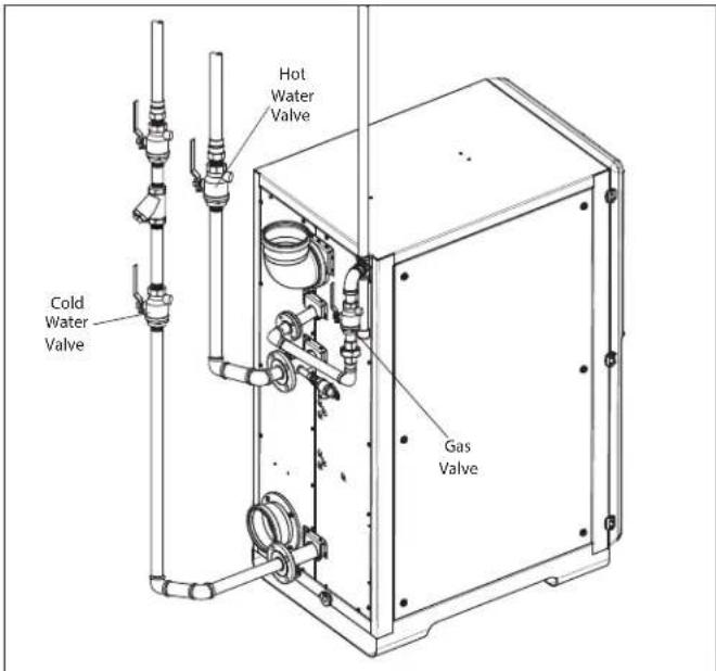
- With the unit OFF, open a nearby hot water faucet and allow the water to run through the unit until all the air is removed from the water lines and from the water heater.
-
If multiple units are being installed, follow these instructions for each unit.
-
Turn ON the power at the electrical junction box and turn ON the ON/OFF switches inside the front cabinet door. The water heater's display panel should turn ON.

- Follow the instructions in this manual and on the unit's display screen. For additional information refer to section "12. Operation" on page 42.
5. Preparation Before Installation
5.1 Selecting an Indoor Installation Site
Note: When installing the water heater, follow all local building codes and the current edition of the National Fuel Gas Code (ANSI Z223.1/NFPA 54) in the USA, or National Gas and Propane Installation Code (CAN/CGA B149.1) in Canada when installing this product.
Note: For water heater installations in Massachusetts, refer to section "16. Requirements for State of Massachusetts" on page 66.
- Select an interior location for the installation. Each installation is unique; therefore, take the time to find the best location for the water heater.
a. Install the water heater near locations that use hot water, such as bathroom, kitchen, or laundry room faucets.
b. Select a location that minimizes the length of the water pipe.
c. If the distances are long or if the faucet or appliance requires "instant" hot water, we recommend running a recirculation line back to the water heater from the farthest fixture.
d. Insulate the hot water supply and recirculation lines.
e. Select a location away from foot traffic and away from areas where dust, debris, chemical agents, or other combustible materials could accumulate.
f. Allow sufficient space for service and maintenance access to all gas, water, and drain connections.
g. Make sure the location meets all building code requirements.
- Minimize the distance that the exhaust gas outlet and air intake inlet must travel to an exterior wall.
a. The exhaust vent outlet must not be located next to a walkway, near soffit vents, crawl space vents, or other areas where condensate (water vapor) could cause damage or create a hazard. Refer to the Venting Clearance Specifications section for additional information.
b. The fresh air inlet vent must be separated from the exhaust vent per guidelines in section "7. Air Intake Inlet and Exhaust Gas Outlet Pipe Connections" on page 22.
c. Contaminated or dirty air drawn into the intake pipe can damage the water heater. The warranty does not cover damage caused by airborne contaminants.
- Locate the unit close to a drain and near gas and water connections.
The water heater produces a significant amount of condensate during normal operation and should be located near a suitable drain where damage from a possible leak will be minimal. Installing the water heater in a location without a drain will void the warranty and the manufacturer will not be responsible for any resulting water damages that may occur. For additional information, refer to the Condensate Line Installation section.
- Locate the water heater and all the water pipes in an area where the ambient temperature always remains above freezing.
a. When the water heater is connected to an electrical power supply, it will automatically prevent the water from freezing inside the unit.
b. The unit's freeze protection system will not prevent the water in the external piping from freezing.
NOTICE
In cold climates, if there is a power failure, the unit's freeze protection system will not operate and can result in water freezing inside the heat engine. To prevent damage to the water heater, turn OFF the gas supply and inlet water valve. Drain the unit completely. Damage caused by freezing water is not covered by the warranty.
-
Select an appropriate location for the combustion air and exhaust pipes to exit the building, as shown in the Venting Clearance Specifications section in this manual.
-
Check the water quality.
Proper maintenance of the water heater is required to ensure that the water meets EPA quality standards. The following table shows the maximum contaminant levels allowed, based on the EPA National Secondary Drinking Water Regulations (40 CFR Part 143.3). Refer to section "17. Warranty" on page 67 for additional information.
If you suspect that your water is contaminated in any way, discontinue use of the water heater and contact an authorized technician or licensed professional.
If the incoming water is known to have a high mineral content or "hardness" (see warranty section), treatment is recommended upstream from the water heater.
5.2 Selecting an Outdoor Installation Site
Note: When installing the water heater, follow all local building codes and the current edition of the National Fuel Gas Code (ANSI Z223.1/NFPA 54) in the USA, or National Gas and Propane Installation Code (CAN/CGA B149.1) in Canada when installing this product.
Note: For water heater installations in Massachusetts, the unit must be installed by a plumber or gas-fitter licensed within the Commonwealth of Massachusetts. Refer to the Requirements for the State of Massachusetts section in this manual for additional information.
- Select a location for the installation. Each installation is unique; therefore, take the time to find the best location for the water heater. Select a location that minimizes the length of the water pipe.
a. Select a location that minimizes the length of the water pipe.
b. If the distances are long or if the faucet or appliance requires "instant" hot water, we recommend running a recirculation line back to the water heater from the farthest fixture.
c. Insulate the hot and cold water supply and recirculation lines to prevent freezing or hot surface danger.
d. Select a location away from foot traffic and away from areas where dust, debris, chemical agents, or other combustible materials could accumulate.
e. Allow sufficient space for service and maintenance access to all gas, water, and drain connections.
f. Make sure the location meets all building code requirements.
g. Contaminated or dirty air drawn into the intake pipe can damage the water heater. The warranty does not cover damage caused by airborne contaminants.
h. Ensure that the air intake is free (and remains free) from grass clippings, wood, landscaping and other debris. It must be higher than the code defined snow line.
i. Install Intellihot outdoor kit IGT-SPR0063. For installation instructions & details, see manual IGT-MNL0019
- Locate the unit close to a drain and near gas and water connections.
The water heater produces a significant amount of condensate during normal operation and should be located near a suitable drain where damage from a possible leak will be minimal. If installing on a roof, installing the water heater in a location without a drain will void the warranty and the manufacturer will not be responsible for any resulting water damages that may occur. For additional information, refer to the Condensate Line Installation section.
- Locate the water heater and all the water pipes in an area where they can be properly insulated.
a. When the water heater is connected to an electrical power supply, it will automatically prevent the water from freezing inside the unit.
b. The unit's freeze protection system will not prevent the water in surrounding pipes from freezing.
NOTICE
If there is a power failure, the unit's freeze protection system will not operate and can result in water freezing inside the heat engine. To prevent damage to the water heater, turn OFF the gas supply and inlet water valve. Completely drain the unit. Damage caused by freezing water is not covered by the warranty.
6. Gas Connection
WARNING
FIRE AND/OR EXPLOSION HAZARD
To avoid serious injury or even death, the gas line installation and the gas line inlet pressure test must be done by a licensed professional.
Always match the water heater with the type of gas supplied to the unit (natural gas or propane). The water heater is factory preset for natural gas.
Make sure the gas line pressures are within normal limits. Pressures outside normal limits can result in poor performance and hazardous operating conditions.
6.1 Quick Reference Installation Instructions
- Determine fuel source; natural gas or propane as shown in "6.2 Fuel Source" on page 17.
- Measure gas pressure as shown in "6.3 Gas Pressure Requirements" on page 17.
- Install a gas pressure regulator and vent line if gas pressure is above maximum recommendations as shown in "6.4 Gas Pressure Regulator" on page 17.
- Measure the length of the supply line as shown in "6.5 Length of Gas Supply Line" on page 18".
- Select the proper gas piping material as shown in "6.5 Length of Gas Supply Line" on page 18.
- Select the proper gas piping diameter as shown in "6.7 Determine Correct Gas Pipe Diameter" on page 18.
- Install a drip leg on the gas piping as shown in "6.8 Gas Pipe Drip Leg and Shut-off Valve" on page 18.
- Install a manual shut-off valve as shown in "6.8 Gas Pipe Drip Leg and Shut-off Valve" on page 18.
- Test all gas line connections for leaks.
NOTICE
Do not fire (operate) the water heater until all connections have been completed and the heat engine is filled with water.
6.2 Fuel Source
- Natural gas is the factory preset.
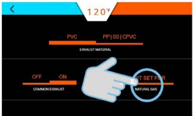
- To convert the unit to propane, refer to the Propane (LPG) Conversion section in this manual.
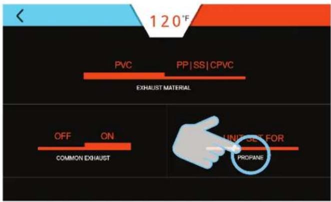
6.3 Gas Pressure Requirements
iQ series water heaters are designed to operate at gas pressures as low as 2.5" WC (at maximum firing rate). Gas inlet pressures to each unit should not exceed 14" WC under any condition (when unit is firing or not firing).
| Natural Gas Static Gas Pressure | |
| Parameters Specifications | |
| Minimum Static Gas Pressure 2.5” W.C. (non-corrugated, black iron) | |
| Recommended Gas Pressure 8” W.C. | |
| Maximum Static Gas Pressure 14” W.C. |
6.4 Gas Pressure Regulator
- If the gas inlet pressure is higher than recommended, install a gas pressure regulator to lower gas pressure to an acceptable level.
- The gas pressure regulator must have the same or higher minimum to maximum modulation range as the iQ model it is regulating. For example, an iQ2001 gas pressure regulator should have a modulation range of 30,000 BTU/h to 2,001,000 BTU/h.
- When multiple units are connected use a dedicated gas pressure regulator for each unit.
- Regulators should be mounted with a minimum of 12" of straight length pipe on either side.
6.4.1 Venting of Gas Supply Regulators
Make sure the gas supply regulator is properly vented by following all local codes and the gas regulator manufacturer's recommendations.
- The vent pipe must be at least the same size as the regulator vent.
- When multiple units are connected, each regulator must have a separate vent line.
- Vent lines must not be connected together or connected with any other appliance requiring external venting.
- When selecting the size, the pipe diameter must be increased by one size for every 20 feet of pipe.
a. Each 90° elbow is equivalent to approximately: 4.5 feet for nominal pipe sizes of up to 1-1/2" 10.5 feet for nominal pipe sizes of up to 4".
b. Each 45° elbow is equivalent to approximately: 2 feet for nominal pipe sizes of up to 1-1/2" 5 feet for nominal pipe sizes of up to 4".
6.5 Length of Gas Supply Line
- Make sure the length supply line is correctly sized.
a. Measure the length of the gas supply line from the gas meter to the water heater or other appliances requiring gas. The diameter of the pipe must be in relation to the length.
b. The total length of gas piping, as well as fitting pressure drop, must be considered when sizing the gas piping. Total equivalent length should be calculated from the meter or source location to the last heater connected.
c. Gas pipe size should be selected on the total equivalent length. The gas volume for cfh flow will be the input divided by the calorific value of the fuel to be supplied.
d. Use the Gas Pipe Sizing tables in this manual or refer to the gas line manufacturers sizing information to determine the correct diameter for the supply pipe.
e. The diameter of the gas lines, shown in the illustration, will vary according to the specific installation requirements.
6.6 Gas Piping Material
- All gas piping and components must comply with NFPA local codes, and utility requirements minimum. Only gas approved fittings, valves, or pipe should be utilized.
- Standard industry practice for gas piping is Schedule 40 iron pipe and fittings. All high and low gas pressure piping systems must comply with local utility and building codes.
- Assembled piping should be clean of all scale, debris, metal particles, or foreign material.
- The piping must be supported from the floor, ceiling, or walls and by the water heater itself.
6.7 Determine Correct Gas Pipe Diameter
Note: The water heater should be the first appliance to be connected to the gas supply line.
- Determine the gas requirement of the water heater(s) and other appliances requiring gas.
- Size the pipe diameter according to the COMBINED total maximum BTUH volume for all the appliances as if they were all operating at the same time. Use the "6.10 Gas Pipe Sizing Tables" on page 20.
- Select the proper header pipe according to the number of units being connected together, as shown in the chart.
| Header Sizing for Multiple iQ Units | ||||
| Number of Heaters | 1234 | |||
| Sch 40 Iron Pipe | 3” 3” 4” | 4” | ||
- The maximum pressure drop from the source to the final water heater must not exceed 0.3" W.C.
- The maximum gas flow rate required is the sum of the maximum inputs of each unit divided by the heat of combustion of the fuel supplied at the location, (approximately 1,030 BTU per cubic foot for natural gas or 2,520 BTU per cubic foot for propane).
Note: The fuel supplier or utility should be consulted to confirm that sufficient volume and normal pressure is provided to the building at the discharge side of the gas meter or supply pipe.
6.8 Gas Pipe Drip Leg and Shut-off Valve
- Install a gas pipe drip leg on each water heater to prevent dirt, condensation, or debris from entering the gas inlet.

- Local codes may require multiple units to have a full size drip leg on the main gas supply line and one on each unit.
- The drip leg should have a removable clean-out cap.
- The gas pipe must not be supported by the drip leg.
- Following local building codes when selecting and installing a shut-off valve.
- Local codes may require multiple units to have a shut-off valve on the main gas supply line and one on each unit.
6.9 Connecting Gas Line to Unit
Note: Always clean the inside of the gas line of any dirt or debris before connecting the piping to the unit.

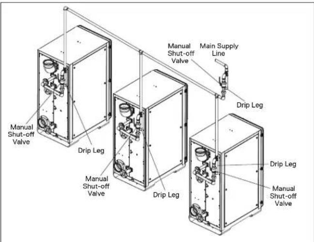
- Install a 6" OD flanged steel coupling and gasket with a short piece of 2" NPT black pipe.

- Install a manual shut-off valve as described in "6.8 Gas Pipe Drip Leg and Shut-off Valve" on page 18

Manual Shut-off Valve
- Install a drip leg in "6.8 Gas Pipe Drip Leg and Shut-off Valve" on page 18.
- Continue installing pipe to reach the main gas supply connection.
- Test all gas pipe connections.
a. All the gas pipe connections should be tested as prescribed in NFPA 54.
b. In multiple unit applications, each unit should be isolated before testing any piping system may exceed the allowable pressure of 14.0" W.C..
NOTICE
Do not fire (operate) the water heater until all connections have been completed and the heat engine is filled with water.
6.10 Gas Pipe Sizing Tables
This information is for reference only. Refer to gas pipe manufacturer specifications for actual delivery capacity. Contact the local gas supplier for actual BTU/ft 3 rating. This data copied from the National Fire Protection Association Article 54 (NFPA 54).
| Pipe Sizes and BTU/h Capacity (NATURAL GAS). Use this table for static gas pressure LESS THAN 5" W.C. | |||||
| Length including fittings (feet) | 1-1/2" 2" 2-1/2" | 3" 4" | |||
| 10 2,090,000 | 4,020,000 6,400,000 11,300 | 0,000 23,100,000 | |||
| 20 1,430,000 | 2,760,000 4,400,000 7,780 | 0,000 15,900,000 | |||
| 30 1,150,000 | 2,220,000 3,530,000 6,250 | 0,000 12,700,000 | |||
| 40 985,000 | 1,900,000 | 5,020,000 5,350,000 10,900,000 | |||
| 50 | 873,000 | 1,680,000 | 2,680,000 | 4,740,000 | 9,660,000 |
| 60 791,000 | 1,520,000 | 2,430,000 4,290,000 8,760,000 | |||
| 70 | 728,000 | 1,400,000 | 2,230,000 | 3,950,000 | 8,050,000 |
| 80 | 677,000 | 1,300,000 | 2,080,000 | 3,670,000 | 7,490,000 |
| 90 | 635,000 | 1,220,000 | 1,950,000 | 3,450,000 | 7,030,000 |
| 100 | 600,000 | 1,160,000 | 1,840,000 | 3,260,000 | 6,640,000 |
| 125 | 532,000 | 1,020,000 | 1,630,000 | 2,890,000 | 5,890,000 |
| 150 | 482,000 | 928,000 | 1,480,000 | 2,610,000 | 5,330,000 |
| 175 | 443,000 | 854,000 | 1,360,000 | 2,410,000 | 4,910,000 |
| 200 | 412,000 | 794,000 | 1,270,000 | 2,240,000 | 4,560,000 |
| Note: BTU/h capacities are based on specific gravity of 0.6, pressure drop of 0.5" WC | |||||
| Pipe Sizes and BTU/h Capacity (NATURAL GAS). Use this table for static gas pressure GREATER THAN 5" W.C. | ||||||
| Length including fittings (feet) | 1-1/4" | 1-1/2" | 2" | 2-1/2" | 3" | 4" |
| 10 | 3,669,000 | 5,497,000 | 10,588,000 | 16,875,000 | 29,832,000 | 43,678,000 |
| 20 | 2,522,000 | 3,778,000 | 7,277,000 | 11,598,000 | 20,503,000 | 30,020,000 |
| 30 | 2,025,000 | 3,034,000 | 5,844,000 | 9,314,000 | 16,465,000 | 24,107,000 |
| 40 | 1,733,000 | 2,597,000 | 5,001,000 | 7,971,000 | 14,092,000 | 20,632,000 |
| 50 | 1,536,000 | 2,302,000 | 4,433,000 | 7,065,000 | 12,489,000 | 18,286,000 |
| 60 | 1,392,000 | 2,085,000 | 4,016,000 | 6,401,000 | 11,316,000 | 16,569,000 |
| 70 | 1,280,000 | 1,919,000 | 3,695,000 | 5,889,000 | 10,411,000 | 15,243,000 |
| 80 | 1,191,000 | 1,785,000 | 3,437,000 | 5,479,000 | 9,685,000 | 14,181,000 |
| 90 | 1,118,000 | 1,675,000 | 3,225,000 | 5,140,000 | 9,087,000 | 13,305,000 |
| 100 | 1,056,000 | 1,582,000 | 3,046,000 | 4,856,000 | 8,584,000 | 12,568,000 |
| 125 | 936,000 | 1,402,000 | 2,700,000 | 4,303,000 | 7,608,000 | 11,139,000 |
| 150 | 848,000 | 1,270,000 | 2,446,000 | 3,899,000 | 6,893,000 | 10,093,000 |
| 175 | 780,000 | 1,169,000 | 2,251,000 | 3,587,000 | 6,342,000 | 9,285,000 |
| 200 | 726,000 | 1,087,000 | 2,094,000 | 3,337,000 | 5,900,000 | 8,638,000 |
| Note: BTU/h capacities are based are based on specific gravity of 0.6, pressure drop of 3.0" WC | ||||||
| Pipe sizes and BTU/h capacity (PROPANE). Use this table for static gas pressure GREATER THAN 5" W.C. | ||||||
| Length including fittings (feet) | 1-1/4" 1-1/2" | 2" 2-1/2" 3" 4" | ||||
| 10 2,350,000 3,5 | 20,000 6,790,000 10,80 | 0,000 19,100,000 39,000,000 | ||||
| 20 1,620,000 2,4 | 20,000 4,660,000 7,430 | 0,000 13,100,000 26,800,000 | ||||
| 30 1,300,000 1,9 | 40,000 3,750,000 5,970,000 | 10,600,000 | 21,500,000 | |||
| 40 | 1,110,000 | 1,660,000 | 3,210,000 | 5,110,000 | 9,030,000 | 18,400,000 |
| 50 985,000 | 1,480,000 2,8 | 40,000 4,530,000 8,000,000 | 16,300,000 | |||
| 60 | 892,000 | 1,340,000 | 2,570,000 | 4,100,000 | 7,250,000 | 14,800,000 |
| 80 | 821,000 | 1,230,000 | 2,370,000 | 3,770,000 | 6,670,000 | 13,600,000 |
| 100 | 763,000 | 1,140,000 | 2,200,000 | 3,510,000 | 6,210,000 | 12,700,000 |
| 125 | 716,000 | 1,070,000 | 2,070,000 | 3,290,000 | 5,820,000 | 11,900,000 |
| 150 | 677,000 | 1,010,000 | 1,950,000 | 3,110,000 | 5,500,000 | 11,200,000 |
| 175 | 600,000 | 899,000 | 1,730,000 | 2,760,000 | 4,880,000 | 9,950,000 |
| 200 | 543,000 | 814,000 | 1,570,000 | 2,500,000 | 4,420,000 | 9,010,000 |
| Note: The line BTU/h capacities are based on specific gravity of 1.5, pressure drop of 0.5" WC. | ||||||
7. Air Intake Inlet and Exhaust Gas Outlet Pipe Connections
! DANGER
Improper venting of the water heater will result in excessive levels of carbon monoxide, which can lead to severe personal injury or death. This water heater must be vented in accordance with the "Venting of Equipment" section of the latest edition of the ANSI Z223.1 / NFPA 54 (Natural Fuel Gas Code) in the USA, or in Canada refer to the "Venting Systems and Air Supply for Appliances" section in the latest version of CAN/CGA B149.1 (Natural Gas and Propane Installation Code), and all applicable local building codes. Vent installation should be performed only by a licensed professional.
WARNING

BREATHING HAZARD CARBON MONOXIDE GAS
- Do not operate flood damaged water heaters.
• Install venting system according to the required codes and material manufacturers specifications. - Do not obstruct fresh air intakes or exhaust outlets. Adequately support all vent system piping.
- Do not place vapor emitting products near water heater or air intake.
- Place working carbon monoxide detectors outside each sleeping area.
- Do not operate the water heater before properly installing the exhaust outlet.
- Visually inspect the vent system and eliminate any possible area where condensation could create a blockage of intake or exhaust air.
Breathing concentrated levels of carbon monoxide, even for a short period of time, will cause brain damage and can even lead to death.
Note: This water heater falls into the Category IV appliance.
7.1 Quick Reference Installation Guide
- Select the desired type of venting system: Two Pipe Vent System (Direct) or Single Pipe Vent System (Power).
"7.3 Two Pipe Vent System (Direct Vent)" on page 24.
"7.4 Single Pipe Venting System (Power Vent)" on page 26. -
Select the desired termination of the air intake inlet and exhaust gas outlet pipe; outside wall or roof.
"7.3.3 Side Wall Air Intake Inlet and Exhaust Gas Outlet Pipe Termination" on page 25.
"7.3.4 Roof Air Intake Inlet and Exhaust Gas Outlet Pipe Termination" on page 25. -
Determine the straight line distance and the number of elbows required to route the air intake inlet and exhaust gas outlet pipes to their termination point.
"7.6 Intake Air Inlet and Exhaust Gas Outlet Pipe Diameter and Length" on page 27. - Determine the diameter of pipe required to properly bring in intake air and vent exhaust gas.
"7.6 Intake Air Inlet and Exhaust Gas Outlet Pipe Diameter and Length" on page 27. - Verify the location of the air intake inlet and exhaust gas outlet terminations are within state and local codes.
"7.7 Venting Clearance Specifications" on page 28. - Select an approved material for the air intake inlet piping.
"7.8 Exhaust Gas Outlet Pipe Materials" on page 29. - Select an approved material for the exhaust gas outlet piping. "7.9 Air Intake Inlet Pipe Vent Materials" on page 30.
7.2 Typical Single Unit Air Intake Inlet and Exhaust Gas Outlet Pipe Installation
- Select one of the two venting configurations: two pipes (direct vent) configuration or with one pipe (power vent) configuration.

- Select the desired termination location and make sure each pipe terminates within all local and state codes.
- Select the desired material for the air intake inlet and exhaust gas outlet pipes.
CAUTION
This water heater has a factory preset control to limit the exhaust gas temperature to 149°F (65°C) when the PVC is selected in the "Flue Type" programming section. As a result, the water heater can be vented with Schedule 40 PVC. If the incoming (or recirculation return) water temperature does not exceed 150°F (66°C), the exhaust gas temperature will not exceed 149°F (65°C).
WARNING
When the unit is set for CPVC (polypropylene pipe), flue temperatures can reach 190°F (88°C). PVC pipe will melt at temperatures above 149°F (65°C) and could therefore result in a fire. Make sure the setting and the type of material being used for the flue are compatible.
For this application use Schedule 80 CPVC or Approved Polypropylene in the USA or Type BH Special Gas Vent Class IIB (CPCV) or Class IC (Polypropylene) that conforms to ULC-S636 in Canada.
Note: If PVC or CPVC pipe is being used, the included polypropylene-to-PVC adapters must be installed.

SAFETY INSTRUCTIONS
On multiple unit installations, the air intake inlet and exhaust gas outlet piping from each water heater must be connected into the properly-sized common piping. Use the table in "7.6 Intake Air Inlet and Exhaust Gas Outlet Pipe Diameter and Length" on page 27 to determine the diameter of the common connecting piping between each individual water heater.
- Determine the length and corresponding diameter for the air inlet pipe and route the pipe to the desired termination location.
a. For termination of the pipe to the outside, continue installing the required pipe to a suitable outside location. Glue all connections, making sure the joints are sealed airtight.
b. Install suitable pipe support hangers every 4 to 5 feet, or as local building codes require.
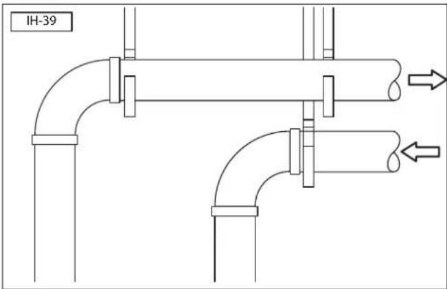
c. To configure the unit for power vent, insert a 3' section of 8" pipe.
- Determine the length and corresponding diameter for the exhaust gas outlet pipe and route it to a suitable outside location.
a. Glue all connections, making sure the joints are sealed airtight.
b. Install all horizontal exhaust gas outlet piping with a minimum 2 degree (1/4" per foot) slope back toward the water heater. This allows any condensate that accumulates in the exhaust gas outlet pipe to properly drain back into the unit.
c. Install suitable pipe support hangers every 4 to 5 feet, or as local building codes require.
SAFETY INSTRUCTIONS
Do not connect any other appliance vents to the water heater inlet or outlet pipes.
- If multiple units are installed, make sure the diameter of the connecting exhaust gas outlet pipe is properly sized for the number of units being installed.
7.3 Two Pipe Vent System (Direct Vent)
7.3.1 Single Unit Configurations
The water heater can be directly vented without any modification using a 8 inch diameter pipe.
The following diagrams represent some typical direct venting configurations and are included to assist in designing the vent system. Possible configurations are not limited to the following diagrams.

7.3.2 Multiple Units Configurations
When more than one unit is installed, refer to "7.6 Intake Air Inlet and Exhaust Gas Outlet Pipe Diameter and Length" on page 27.
Connecting multiple units together requires proper sizing of the air intake inlet and exhaust gas outlet pipes. Up to two (iQ3001) or three (iQ2001) water heaters can be connected (cascading) together. Units which share a common vent must be connected together in a cascading configuration, as described in "13. Connecting Multiple Units" on page 53"13. Connecting Multiple Units" on page 53.
The following diagrams represent some typical direct venting configurations and are included to assist in designing the vent system. Possible configurations are not limited to the following diagrams.

7.3.3 Side Wall Air Intake Inlet and Exhaust Gas Outlet Pipe Termination
- Terminate the air intake inlet pipe with a 90° elbow (angled down). Use a flange and PVC screen (not supplied).
- Terminate the exhaust gas outlet pipe on the exterior wall at least 12" above ground and at least 18" away from the air intake inlet pipe, or as required by local building codes. In areas of high snow fall, protect the vent terminations from blockage. Use a flange and PVC guard.

Single unit.

Multiple units.
Note A: The distance between any exhaust gas outlet and air intake inlet pipe should be between 18 and 36 inches apart. If this minimum specification cannot be met, the air intake inlet and exhaust gas outlet pipes should be 72 inches apart or more.
- To avoid moisture and frost build-up to openings on adjacent homes, use 45° elbows, 90° elbows, or tees for the vent termination to direct the exhaust gas fumes away from the building.
7.3.4 Roof Air Intake Inlet and Exhaust Gas Outlet Pipe Termination
Venting the unit through the roof is also an option. With this installation method, the terminations must extend at least 12" over maximum potential snow levels, or as required by local building codes. In areas of high snow fall, protect the vent terminations from blockage.
Terminate the air intake inlet pipe with a 90° elbow (angled down). A suitable roof flashing and vent cap (not supplied) should be installed.

Single unit.

Multiple units.
Note A: The distance between any exhaust gas outlet and air intake inlet pipe should be between 18 and 36 inches apart. If this minimum specification cannot be met, the air intake inlet and exhaust gas outlet pipes should be 72 inches apart or more.
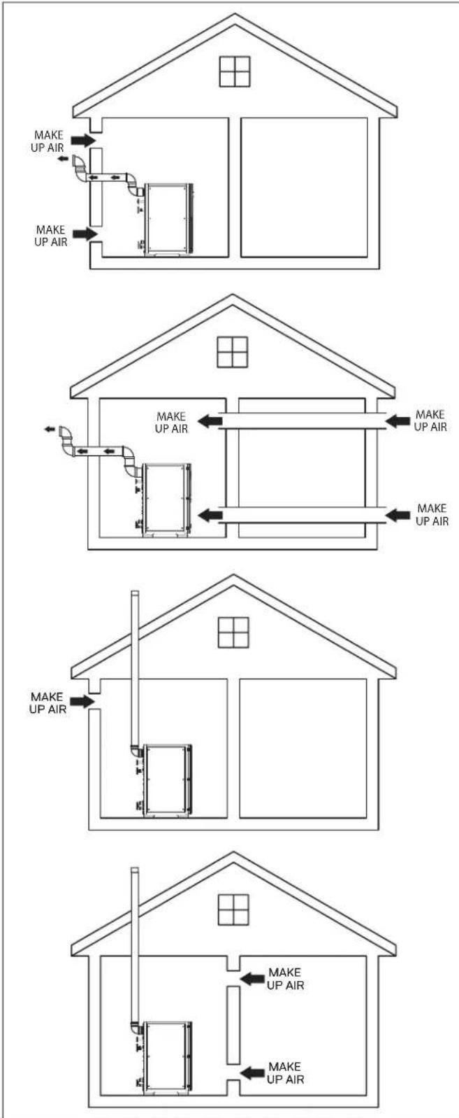
7.4 Single Pipe Venting System (Power Vent)
7.4.1 Single Unit
The following illustrations represent some typical power venting configurations and are included to assist in designing the vent system. Possible configurations are not limited to these designs.
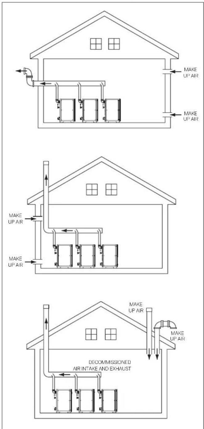
7.4.2 Multiple Units
When installing multiple units, refer to "7.6 Intake Air Inlet and Exhaust Gas Outlet Pipe Diameter and Length" on page 27.
Connecting multiple units together requires proper sizing of the air intake inlet and exhaust gas outlet pipes. Up to two (iQ3001) or three (iQ2001) water heaters can be connected (cascading) together. Units which share a common vent must be connected together in a cascading configuration, as described in "13. Connecting Multiple Units" on page 53"13. Connecting Multiple Units" on page 53.
7.5 Combustion Air Requirements
When using the single exhaust gas outlet pipe or power vent method, the following table outlines the required opening sizes for the combustion and ventilation air coming into the room and the required CFM requirements per water heater:
SAFETY INSTRUCTIONS
Do not operate the unit in an area that will draw in outside air contaminated with high levels of dust, sawdust, aerosols such as paint, or other airborne contaminants.
If necessary, purchase and install appropriate air screens and follow a regular cleaning program to ensure an adequate supply of clean, outside combustion air.
| Required Combustion & Ventilation Air Opening Sizes (sq. in) Per Heater Per Boiler Room: | |||||||
| Model Input | Air Type | Required CFM | Air is drawn directly from outside into the mechanical room | Air is drawn from another interior space inside the building | |||
| through two openings*, direct or vertical | through one opening** | through two horizontal ducts | |||||
| iQ2001, Gen II 1,999,999 | Combustion Air | 360 500 | 666 | 1,000 2000 | |||
| Ventilation Air | 360 500 1,000 | 2000 | |||||
| iQ3001, Gen II 3 | 001,000 | Combustion Air | 540 750 | 1000 | 1,500 3001 | ||
| Ventilation Air | 540 750 1,500 | 3001 | |||||
| *Where two openings are used, one must be within 12 inches of the floor and the other opening must be within 12 inches of the ceiling of the mechanical room.**Where one opening is required, it must be located within 12 inches of the ceiling. | |||||||
7.6 Intake Air Inlet and Exhaust Gas Outlet Pipe Diameter and Length
The iQ2001 and iQ3001 come factory installed with 8 inch polypropylene (PP) venting. The following chart outlines the maximum length of venting allowable for each model.
A vent system's length is calculated by adding the length of all straight runs used (both horizontal and vertical) and then adding the equivalent lengths of each turn (90° or 45° elbow) used in the system.
SAFETY INSTRUCTIONS
A vent system's length must not exceed the maximum length outlined in the chart below.
| Maximum Pipe Length in Feet | |||||||
| Number of Units | Venting Type | ||||||
| 8" Diameter | 10" Diameter | 12" Diameter | |||||
| iQ2001 | iQ3001 | iQ2001 | iQ3001 | iQ2001 | iQ3001 | ||
| 1 | 1 pipe - PV | 155 | 70 | 460 | 220 | 500 | 220 |
| 2 pipe - DV | 75 | 35 | 230 | 110 | 250 | 110 | |
| 2 | 1 pipe - PV | 40 | 130 | 60 | 315 | 150 | |
| 2 pipe - DV | 20 | 65 | 30 | 155 | 75 | ||
| 3 | 1 pipe - PV | 60 | 150 | 70 | |||
| 2 pipe - DV | 30 | 75 | 35 | ||||
| PV = Power VentDV = Direct VentNote: Reduce the maximum equivalent length above by 5 feet per 90° elbow used and by 2 feet per 45° elbow used. Do not exceed the above set limits. | |||||||
7.7 Venting Clearance Specifications

| Venting Clearance Specifications | |||
| Item Description | Clearance Distance | ||
| USA 1 | Canada 2 | ||
| A Clearances above grade, veranda, porch, deck, or balcony 1 foot 1 foot | |||
| B Clearances to window or door that may be opened 1 foot** 3 feet | |||
| C Clearances to permanently closed window ** | |||
| D Vertical clearance to a ventilated soffit, eves, or overhang ** | |||
| E Clearances to unventilated soffit, eves, or overhang ** | |||
| F Clearances to outside corner ** | |||
| G Clearances to inside corner ** | |||
| H | Clearances to each side of centerline extended from meter/regulator | * | 3 feet within a height 15 feet above meter/regulator assembly |
| I | Clearances to gas meter regulator vent outlet | * | 3 feet |
| J | Clearances to non-mechanical air supply inlet or combustion air inlet to any other appliance | 1 foot** | 3 feet |
| K | Clearances to mechanical air supply inlet | 3 feet above if within 10 feet horizontally | 6 feet |
| L | Clearances to above paved sidewalk or paved driveway on public property | * | 7 feet |
| M | Clearances under veranda, porch, deck, or balcony | * | 1 foot |
| *Per local/gas supplier codes. Use clearances in accordance with local building codes and local gas supplier.** For single vent pipe/direct 4 feet (1.2 m) below or to the side of opening and 1 foot above opening.1 In accordance with Z223.12 In accordance with CSA B149.1 | |||
Note: The vent for this appliance shall not terminate;
Over public walkways; or
Near soffit vents or crawl space vents or other areas where condensate or vapor could create a nuisance or hazard or cause property damage; or
Where condensate vapor could cause damage or could be detrimental to the operation of regulators, relief valves, or other equipment.
7.8 Exhaust Gas Outlet Pipe Materials
SAFETY INSTRUCTIONS
For Canadian installations, plastic exhaust gas outlet piping must comply with CAN/CGA B149.1 and be certified to the Standard For Type BH Gas Venting Systems, ULC-S636. Components of this listed system must not be interchanged with other vent systems or unlisted pipes or fittings. All plastic components and specified primers and glues must be from a single system manufacturer and must not be intermixed with another system manufacturer's products.
All units come factory installed with 8 inch polypropylene (PP) venting. A polypropylene to PVC adapter is included with each unit to enable the use of PVC exhaust gas outlet pipe. The maximum allowable venting distances are the same regardless of vent material selected.
The materials listed in the tables below outline the acceptable exhaust gas outlet pipe materials:
| United States Exhaust Gas Outlet Pipe Standards | |
| Material Description* | |
| Exhaust Gas Outlet Pipe | PVC Schedule 40 (ASTM D1785) |
| CPVC Schedule 40, 80 | |
| Approved Polypropylene | |
| AL29-4C Stainless Steel | |
| Canadian Exhaust Gas Outlet Pipe Standards | |
| Material Description (approved to ULC-S636)** | |
| Exhaust Gas Outlet Pipe | Type BH Special Gas Vent Class IIA (PVC) |
| Type BH Special Gas Vent Class IIB (CPVC) | |
| Type BH Special Gas Vent Class IIC (Polypropylene) | |
| Type BH Special Gas Vent Class I (AL29-4C Stainless Steel) | |
| *Note: Use of cellular core PVC (ASTM F891), cellular core CPVC, or Radel (polyphenylsulfone) in nonmetallic venting systems is prohibited. Covering non-metallic vent pipe and fittings with thermal insulation is prohibited.**Note: The components (pipe, fittings, primers, and glues) must be from a single manufacturer; do not interchange. Follow the vent manufacturer's certified instructions. | |
SAFETY INSTRUCTIONS
Do not use cellular foam core pipe to vent exhaust gases.
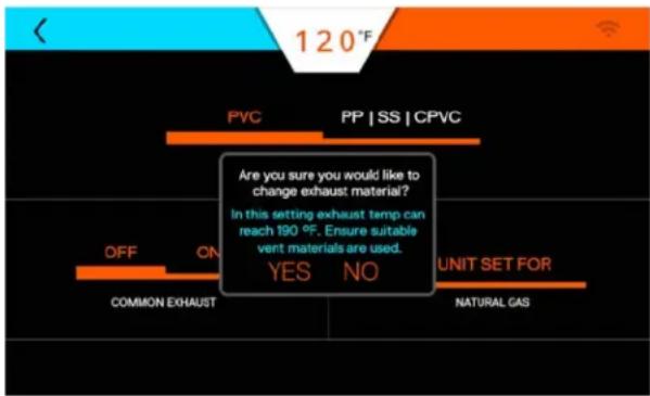
This water heater has a built-in exhaust gas outlet temperature control that limits the exhaust gas temperature to a maximum of 149° F ( 65° C) for PVC pipe. In commercial applications which require higher water temperatures, exhaust gas temperature can reach 190° F ( 88° C) and require materials such as polypropylene (PP), stainless steel (SS), or CPVC.
If the temperature approaches the upper limit, the burner will turn off automatically to protect the vent pipe. Once the exhaust gas temperature has dropped to a normal operating level, the unit will automatically restart.
If the inlet/return water temperature will exceed 150° F ( 66° C), do not use PVC pipe. Follow the display prompts to set the maximum water temperature for the exhaust gas outlet pipe material being used.

7.9 Air Intake Inlet Pipe Vent Materials
The air intake inlet pipe can be of any plastic or metal vent material available. ABS, PVC, polypropylene, galvanized steel, and/or flexible corrugated ducting are all examples. When using a corrugated material, ensure there is no inadvertent crimping or blockage to the air intake inlet pipe.
Refer to the table below for a list of approved materials.
| United States Vent Pipe Standards | |
| Material Description | |
| Vent Pipe | PVC Schedule 40 |
| CPVC Schedule 80 | |
| Approved Polypropylene | |
| Canadian Vent Pipe Standards | |
| Material Description | |
| Vent Pipe | Type BH Special Gas Vent Class IIA (PVC) |
| Type BH Special Gas Vent Class IIB (CPVC) | |
| Type BH Special Gas Vent Class IIC (Polypropylene) | |
Note: In addition to these charts, it is recommended to consult the most recent edition of ANSI Z223.1/NFPA 54 or CAN/CGA B149.1, as well as all applicable local codes and regulations when selecting vent pipe materials.
7.10 Recommended Exhaust Gas Outlet Pipe Transitions
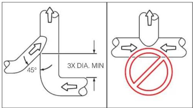
Do not direct exhaust gas from opposite directions. Use a 45 degree transition, as shown.

![graph TD A["Input Arrow"] --> B["Process Step"] B --> C["Output Arrow"]](/content/2026/05/955810/images/66e8b6bcd3c92879242dad17deff85355b62ad3ff2c09d31afbc36ca5355a81f.jpg)


Do not transition into a reducer or use a t-fitting. Transitions should always be directed into a straight run of pipe.

Do not use 90 degree transition into a reducer or a straight pipe.

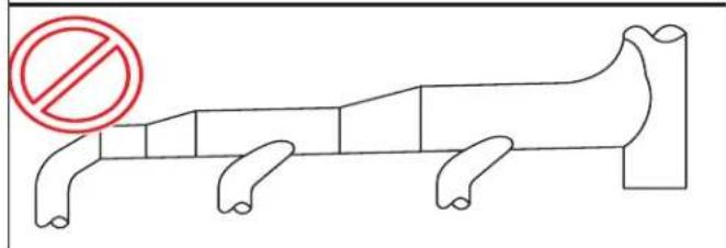
Do not use reducers in a straight run of pipe.
8. Water Connections
Note: For flow rate changes faster than 10 gpm in one second, a water hammer arrester must be installed to prevent damage to the water heater.
8.1 Quick Reference Installation Instructions
- Install the hot water piping.
NOTICE
When tightening any fittings to the connections on the water heater, care should be exercised not to overtighten these joints and damage the unit.
- Install the cold water piping.
- Make sure the pressure relief valve is installed. If necessary, install a customer supplied relief valve.
- Install a condensate drain line.
- After installation has been completed, test the water heater for proper flow and inspect for leaks.
- Run the hot water for a few minutes and then clean the inlet water strainer located on the cold water inlet fitting. This strainer must be cleaned periodically to maintain proper water flow.
8.2 Hot Water Connection
Install and connect the hot water lines. Keep the hot water pipes as short as possible to deliver hot water to the fixtures quickly. If an optional hot water storage tank is required, connect the hot water lines to this tank also.
Since each installation is different, it is up to the installer to route the water lines using the most efficient routing. The drawings shown here are only suggestions indicating the items needed for the installation.
CAUTION
To prevent adverse health issues, only materials (pipes, fittings, valves, solder, etc.) that are approved for use in potable water systems should be used.
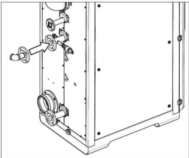
- Connect a short section of 3" copper water line to the water heater's hot water connection.
a. The incoming flange, flange gasket, and stainless steel flange bolts must be supplied by the installer.
b. The flange connection uses a 7.5" OD, four-bolt flanged assembly.
c. The gasket material specs are an EPDM material with a minimum rating of 210° F continuous service or higher.
d. The flange bolts are a 3/4" diameter stainless steel. Also install stainless steel washers on both sides of the flange.
e. Route the water lines from the water heater to the connection with the building's water pipes in the most efficient manner.
WARNING
To prevent serious personal injury, do not install any shut-off device between the water heater and the pressure relief valve. This valve is designed to release abnormally high pressure within the water heater in the event of a system problem.
- If not factory installed, install a 1" 150 psi maximum pressure relief valve, as required by your local code into the port on the outlet piping of the unit.

NOTICE
The pressure relief valve must be rated at 150 psi, the maximum btu/h input of the unit, and comply with all local building codes and standards. Do not install any restrictions or other valves in the pressure relief line.
- Install and route a discharge pipe from pressure relief valve to within 6 inches of the floor and directed away from walkways or other appliances.
a. Route the relief valve to within 6 inches of the floor to prevent injury in the event of a discharge.
b. The diameter of the pipe from the relief valve must be equal to the outlet size of the relief valve.
c. Do not use reducers in the outlet piping.
d. Do not install any valves, restrictions, or other blockages in the outlet piping.
e. For multiple unit installations, the outlet piping must not be connected together. Each line must be separately routed to a suitable drain.

- Following local building codes, install a manual shut-off valve.

- Connect the unit to the building's hot water lines. If multiple water heaters are being installed, the diameter of both the main cold water lines and the main hot water lines need to be sized appropriately.
- To conserve energy, insulate all hot water piping.
SAFETY INSTRUCTIONS
Do not insulate the pressure relief valve.
- With the unit OFF, open a nearby hot water faucet and allow the water to run through the unit until all the air is exhausted from the water lines and from the water heater.
- Leak test the water piping. Repair any leaks immediately.
Note: For energy conservation, the hot water pipes should be insulated. Also insulate any recirculation water lines.
8.3 Cold Water Connection
Install and connect the cold water lines.
Note 1: If the incoming water is known to have a high mineral content or "hardness" (see warranty section), treatment is recommended upstream from the water heater.
Note 2: A water inlet stainer must be installed prior to use. This strainer must be inspected and cleaned after initial operation of 3 hours. Subsequently inspect the strainer at least every 3 months to establish a cleaning schedule.
When the water heater is installed in a closed loop recirculation system, and if the cold water supply line has a back flow preventer, then an expansion tank should be installed to allow for water expansion.
CAUTION
To prevent adverse health issues, only materials (pipes, fittings, valves, solder, etc.) that are approved for use in potable water systems should be used.
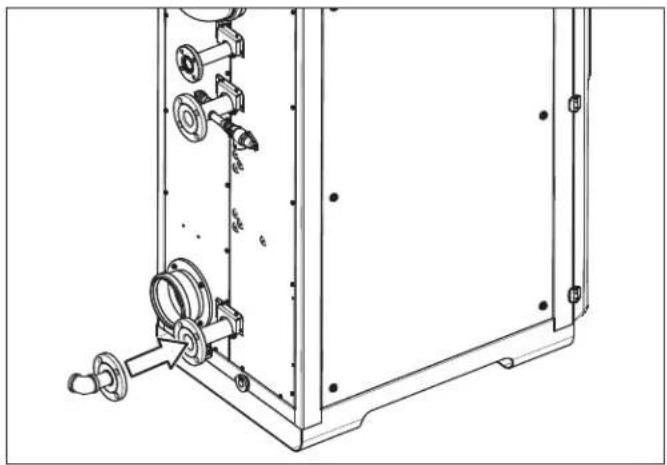
- Connect a short section of 3" copper water line to the water heater's cold water connection.
a. The incoming flange, flange gasket, and stainless steel flange bolts must be supplied by the installer.
b. The flange connection uses a 7.5" OD, four-bolt brass flanged assembly.
c. The gasket material specs are an EPDM material with a minimum rating of 210° F continuous service or higher.
d. The flange bolts are a 3/4" diameter stainless steel. Also install stainless steel washers on both sides of the flange.
e. Route the water lines from the water source to the water heater connection in the most efficient manner.
- Following local building codes, install a manual shut-off valve.

- Connect the unit to the building's cold water lines. If multiple water heaters are being installed, the diameter of the main cold water line needs to be sized appropriately.
Note: Isolation valve kits can be used if incoming water treatment is anticipated (such as a water softener) due to hardness levels or heavy usage of the unit.
-
With the unit OFF, open a nearby cold water faucet and allow the water to run through the unit until all the air is exhausted from the water lines and from the water heater.
-
Leak test the water lines. Repair any leaks immediately.
8.4 Condensate Drain Line
Due to its efficient design, the water heater produces condensate (water) as a normal by-product of heating the water.
This condensate is acidic, with a pH level between 3 and 4. Local building codes may require an in-line neutralizer to be installed (not included) to treat this water.
The maximum condensate flow rate is 21.6 GPH.
- Install a 3/4" flexible hose to the hose connection on the water heater.
a. If a floor drain is used to remove the discharge, route the drain hose over or into the drain.
b. Long drain lines should contain a union to facilitate servicing the unit or cleaning the drain line.

- If required, install an in-line neutralizer to treat the acidic condensate. Follow all the installation instructions included with the neutralizer.

iB3001 telliBot Condensate Neutralizer
Note: Whenever a condensate neutralizer is required, it is suggested that a iB3001 telliBot Condensate Neutralizer be used. When used in a cascading application, use one telliBot unit per water heater.

A 1 inch minimum distance is required between the condensate outlet of the water heater and the outlet of the condensation neutralizer, as shown. This minimum distance is also required when using a condensate pump.
- If a floor drain is not available, a condensate pump can be used to pump the condensate to the drain.

a. If a condensate pump is being used, the water heater may need to be raised off the floor to accommodate the height of the pump.
b. Route the hose from the condensate pump to a nearby floor drain or drain pipe.
c. The condensate pump must be supported by the floor or other means; it cannot be supported by the connecting pipes.
9. Electrical Power
9.1 Electrical Recommendations
WARNING
To avoid serious injury or even death, follow all applicable local, state, and national regulations, mandates, and building codes for guidelines to install the electrical power supply.
Electrical code requirements are different in the USA and Canada. Refer to and follow the local building codes, the latest edition of the National Electrical Code (NFPA 70) in the USA, or the CGA C22.1 Canadian Electrical Code - Part 1.
For a single iQ2001 water heater, the circuit breakers should be at least 20 amps per circuit. Please follow the local electrical code in determining the appropriate breaker size.
A minimum 30 Amp circuit breaker, per circuit, should be installed for the iQ3001. Please follow the local electrical code in determining the appropriate breaker size.
For multiple units, install an adequately sized breaker. Installing a separate circuit breaker for each unit is required to isolate units during service or repair.

Note: For an electrical wiring schematic, refer to "15.2 Complete Wiring Diagram (all models)" on page 58 for additional information.
NOTICE
The electrical connections for the water heaters are polarity sensitive. Before connecting the water heater to the power source, test the polarity of the electrical circuit.
9.2 Connection Instructions
-
On single unit installations, make sure the electrical circuit being used is wired with appropriately sized wire (or at least 10 gauge) wire and grounded with an appropriately sized circuit breaker. Please note that the wire size varies based on the breaker size. The electrical power required for the water heater is 120V AC at 60 Hz (multiple circuits).
-
Remove the four cover screws and open the cover.

WARNING
To avoid serious injury or even death from electrical hazards, an additional ON/OFF electrical junction box should be installed near the water heater. This switch will allow power to be removed from the water heater prior to service or in the case of an emergency.
- Route a customer-supplied appropriately-sized, wire with ground from an electrical junction box with an ON/OFF switch through the back panel of the water heater. Route the wire through the cabinet to the junction box.
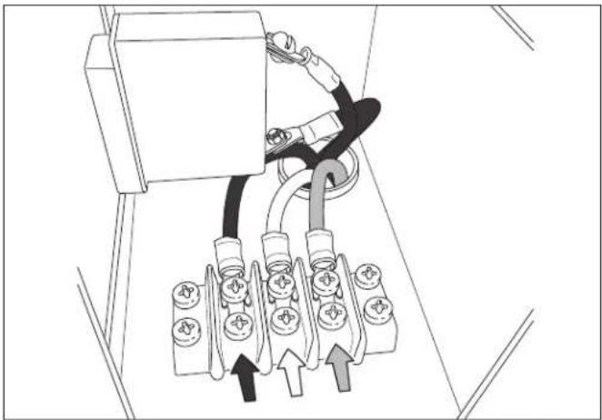
- On the opposite side of the block from the factory installed wiring, connect the white wire to the white terminal, the black wire to the black terminal, and the green ground wire to the green terminal (for each circuit).
- If multiple units are being installed, install each with a dedicated, appropriately sized circuit breaker. For installing multiple units, refer to "13. Connecting Multiple Units" on page 53 for additional information.
10. Adjusting CO2 Level
10.1 General Information
This procedure is required:
1) only during installation in a high-altitude location over 8,000 feet, or
2) when converting the unit from natural gas to propane.
This procedure should be performed only by a qualified technician.
! DANGER
A concentration of carbon monoxide (CO) as small as 0.04% (400 parts per million) in the air can be fatal. When making High Fire and/or Low Fire adjustments, CO levels must be monitored using a flue gas analyzer and must not exceed 400 ppm of CO at any time during the operation.
Adjusting the “Low Fire screw” or the “High Fire screw” even in small increments can result in a significant increase in CO concentration. To avoid serious injury or death, DO NOT make any adjustments to the gas valve without monitoring the exhaust gases with a functional and calibrated flue gas analyzer.
| CO2and CO Standards | ||
| Description CO | Range (%) Max. | CO Level (ppm) |
| Natural Gas | ||
| High Fire 9.1% to | 9.3% < 200 ppm | |
| Low Fire 9.1% to | 9.3% < 60 ppm | |
| Propane | ||
| High Fire 10.1% to | 10.5% < 200 ppm | |
| Low Fire 10.1% to | 10.5% < 60 ppm | |
NOTICE
The values listed in the table are for nominal conditions. Variables such as gas pressure, heating value of the gas, humidity, and temperature of combustion air can impact CO and CO2 values. Changes in these variables can result in different CO and CO2 values on the same water heater.
A qualified service technician must use a calibrated flue gas analyzer to adjust the gas valve to achieve the desired CO₂ and CO values.
Before any adjustments are made, the service technician must confirm the static gas pressure meets these minimum requirements. Natural Gas - 8" W.C. Propane - 11" W.C.
10.2 Adjustment Procedure
- Remove the side covers.
- Locate the gas valve on each heat engine. There are eight heat engines in iQ2001 and twelve in iQ3001.

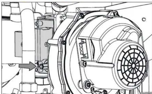
- Remove the plug from the test port on the exhaust manifold. Insert a calibrated flue gas analyzer into the test port.
- Follow the display screens.

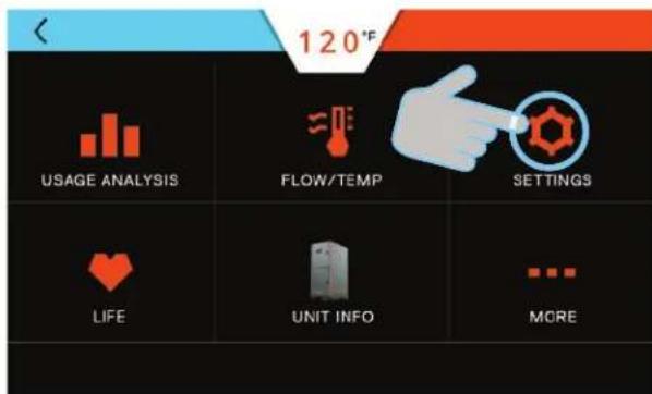

NOTICE
Do NOT change the blower speed settings. This adjustment MUST be performed by factory personnel ONLY. Changing this setting WILL VOID the warranty!
- Create a hot water flow of at least 8.0 GPM as shown on the display screen.
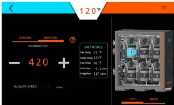
Note: If flow rate is inadequate, a pop-up message will notify to increase the flow.

- At at a flow rate of 8.0 GPM, Heat Engine 1 (H1) will start.
- Allow three minutes of operation at High Fire.
-
Record "initial output" in Hire Fire Recorded Values table.
-
If the CO2 values are within appropriate range, proceed to Step 10, otherwise continue.
a. Use a flat blade screwdriver to turn the High Fire screw clockwise to decrease and counterclockwise to increase the CO2 value.
b. Adjust in 1/4 turn increments.
c. Wait three minutes to stabilize flue gas readings and recheck values.
d. Adjust until values fall with specified range.

- Once the desired values are achieved, record the new High Fire CO 2 “adjusted values” in the table.
| CO2and CO Standards | ||
| Description CO | 2Range Max | CO Level |
| Natural Gas High Fire 9.1% | to 9.3% < 200 ppm | |
| Propane High Fire 10.1% to | 10.5% < 200 ppm | |
| High Fire Recorded Values | ||
| Date ____ / ____ / ____ | ||
| Heat Engine (1) | Initial Output Adjusted Value | |
| CO2 Value % | ||
| Max CO ppm | ||
| Heat Engine (2) | Initial Output Adjusted Value | |
| CO2 Value % | ||
| Max CO ppm | ||
| Heat Engine 3) | Initial Output Adjusted Value | |
| CO2 Value % | ||
| Max CO ppm | ||
| Heat Engine (4) | Initial Output Adjusted Value | |
| CO2 Value % | ||
| Max CO ppm | ||
| Heat Engine (5) | Initial Output Adjusted Value | |
| CO2 Value % | ||
| Max CO ppm | ||
| Heat Engine (6) | Initial Output Adjusted Value | |
| CO2 Value % | ||
| Max CO ppm | ||
| Heat Engine (7) | Initial Output Adjusted Value | |
| CO2 Value % | ||
| Max CO ppm | ||
| Heat Engine (8) | Initial Output Adjusted Value | |
| CO2 Value % | ||
| Max CO ppm | ||
| Heat Engine (9) | Initial Output Adjusted Value | |
| CO2 Value % | ||
| Max CO ppm | ||
| Heat Engine (10) | Initial Output Adjusted Value | |
| CO2 Value % | ||
| Max CO ppm | ||
| Heat Engine (11) | Initial Output Adjusted Value | |
| CO2 Value % | ||
| Max CO ppm | ||
| Heat Engine (12) | Initial Output Adjusted Value | |
| CO2 Value % | ||
| Max CO ppm | ||
-
From the display screen, press Heat Engine 2 (H2) and repeat the High Fire procedure for all heat engines.
-
Press LOW FIRE on the display screen.
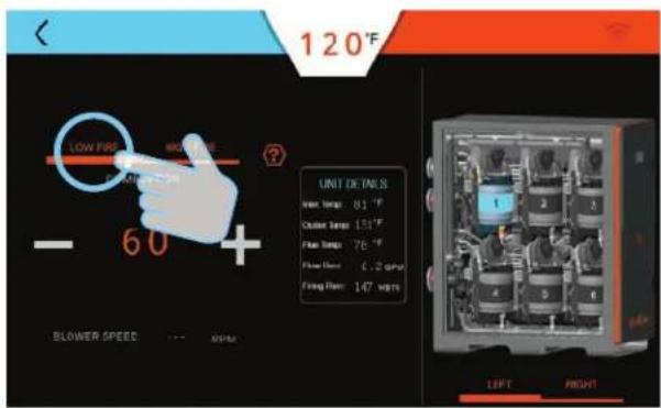
- Record "initial output" in Low Fire Recorded Values table.
| CO2 and CO Standards | ||
| Description CO | 2 Range Max. | CO Level |
| Natural Gas Low Fire 9.1% to 9.3% < 60 ppm | ||
| Propane Low Fire 10.1% to 0.5% < 60 ppm | ||
| Low Fire Recorded Values | ||
| Date ____ / ____ / ____ | ||
| Heat Engine (1) Initial Output Adjusted Value | ||
| CO2 Value % | ||
| Max CO ppm | ||
| Heat Engine (2) Initial Output Adjusted Value | ||
| CO2 Value % | ||
| Max CO ppm | ||
| Heat Engine 3) Initial Output Adjusted Value | ||
| CO2 Value % | ||
| Max CO ppm | ||
| Heat Engine (4) Initial Output Adjusted Value | ||
| CO2 Value % | ||
| Max CO ppm | ||
| Heat Engine (5) Initial Output Adjusted Value | ||
| CO2 Value % | ||
| Max CO ppm | ||
| Heat Engine (6) Initial Output Adjusted Value | ||
| CO2 Value % | ||
| Max CO ppm | ||
| Heat Engine (7) Initial Output Adjusted Value | ||
| CO2 Value % | ||
| Max CO ppm | ||
| Heat Engine (8) Initial Output Adjusted Value | ||
| CO2 Value % | ||
| Max CO ppm | ||
| Heat Engine (9) Initial Output Adjusted Value | ||
| CO2 Value % | ||
| Max CO ppm | ||
| Heat Engine (10) | initial Output Adjusted Value | |
| CO2 Value % | ||
| Max CO ppm | ||
| Heat Engine (11) | Initial Output Adjusted Value | |
| CO2 Value % | ||
| Max CO ppm | ||
| Heat Engine (12) | initial Output Adjusted Value | |
| CO2 Value % | ||
| Max CO ppm | ||
- Adjust the Low Fire screw while the burner operates at low fire using a 2mm hex wrench. Turn clockwise to increase CO2 and counterclockwise to decrease CO2 .
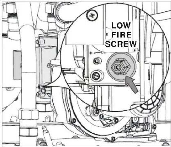
-
Once the desired values are achieved, record the new Low Fire CO, "adjusted values" in the table.
-
From the display screen, press Heat Engine 2 (H2) and repeat the Low Fire procedure for all heat engines.

-
When all heat engines have been properly adjusted, turn off water flow.
-
Remove the flue gas analyzer probe and plug the test port.
-
Press the back button to return to the main screen.

-
Check for gas leaks using a leak detector.
-
Install side panel covers. If converting to propane, proceed to section "11. Natural Gas to Propane Conversion" on page 40.
11. Natural Gas to Propane Conversion
SAFETY
INSTRUCTIONS
A qualified service technician MUST make the required changes to convert the water heater from Natural Gas to Propane.
11.1 General Information
Note: This conversion process also requires the CO2 levels to be adjusted. Refer to “10. Adjusting CO2 Level” on page 36 for instructions.
Before converting the unit for propane, verify the current gas inlet pressure meets the recommended pressure and record it in the space below.
| Propane Static Gas Pressure | |
| Parameters Specifications | |
| Minimum Static Gas Pressure 8” W.C. (non-corrugated, black iron) | |
| Recommended Gas Pressure 11” W.C. | |
| Maximum Static Gas Pressure 13” W.C. |
Current Static Propane Gas Pressure ____W.C.
Date ____
Note: This conversion process also requires the CO2 levels to be adjusted. Refer to "10. Adjusting CO2 Level" on page 36 for instructions.
11.2 Conversion Procedure
- Follow these steps before repositioning the DIP switches.
a. Turn the water heater OFF using the display screen.

b. Place the circuit breaker for the water heater at the main electrical panel in the OFF position. Verify there is no power to the unit(s).

c. Locate DIP Switch 1 on each circuit board (located on each engine).
Note: Eight control boards in iQ2001 and twelve control boards in iQ3001.

d. Move each DIP switch downward into the Propane position.
| DIP Switch Settings (Réglages des commutateurs DIP) | ||
| SW1 Propane | ON ON | Natural Gas(Gaz naturel) |
e. Reset the circuit breaker to the ON position. Turn the water heater ON using the display screen.

- Follow the display screens to check if the unit is now set to propane.

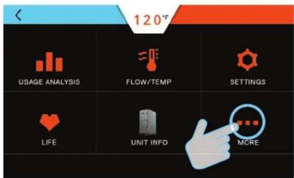


- Refer to section "10. Adjusting CO2 Level" on page 36 in this manual for instructions to adjust CO₂ levels.
12. Operation
12.1 Control Panel

Main Menu Screen

Selecting the Menu button brings up this screen.

A sleep mode screen will appear after a period of inactivity.
12.2 Turning Water Heater ON and OFF
- When power is applied to the water heater or the electrical switches are turned ON, the Main Menu screen will automatically appear.
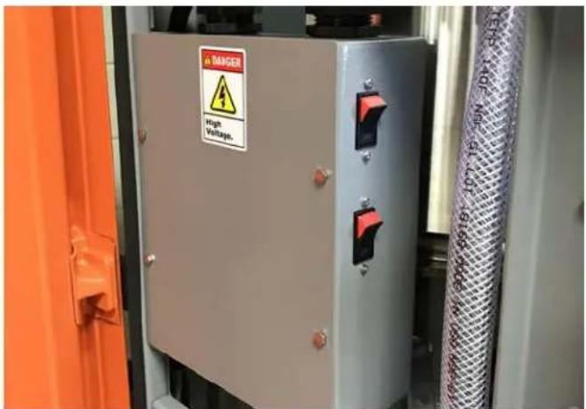

- To turn the water heater OFF, press and hold the Power button in the upper left of the screen.

- Press the Power button to turn the unit ON.

WARNING
Turning the unit OFF does not disconnect it from the power source. Whenever working around electrical components within the water heater, turn off the power at its source. Touching live electrical components can cause serious injury or death.
12.3 Setting the Time


Press the Up/Down arrows to make adjustments. Press the Back button to return to the main screen.
12.4 Adjusting the Water Temperature
Note: The outlet water temperature is factory preset to 120°F, however these commercial water heaters are capable of heating water to 190°F.
! DANGER
DANGER

Hot water temperature over 125°F (52°C) can cause severe burns instantly or death from scalding. Children, the disabled, and the elderly are at the highest risk of being scalded. Do not leave children or the infirm unsupervised. Check temperature of hot water before taking a shower or
bath. To control water temperature to a particular faucet, temperature limiting valves can be installed by your service professional.
All water faucets must be closed before changing the temperature setting. The unit must not be operating.
- Firmly press the slider and slide it to the right to increase the temperature or to the left to decrease. Firmly hold the icon until the display reaches the desired temperature.


- For finer temperature adjustments, use the (+) and (−) icons.

- Follow any prompts shown on the screen.
12.5 Security
12.5.1 Setting Passcode Protection
It is not necessary to set a passcode for the water heater to function properly. This feature is available to help prevent unauthorized access to the unit.
If a passcode is set, it must be entered prior to accessing the main screen.


Press ON/OFF and follow the prompts.

12.5.2 Changing Passcode
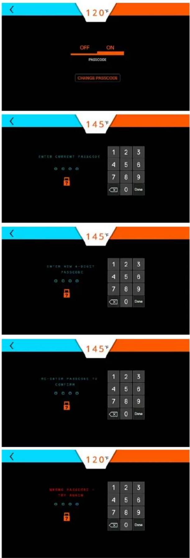
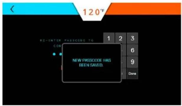
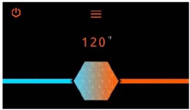
12.5.3 Forgot Passcode
If the unit passcode is lost or forgotten, press the "?" icon and call technical support.
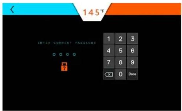


12.6 iNTouch
If equipped, the iNTouch icon will be active.


12.7 Life Screen
These screens provide a visual indication of the remaining life of various components.
Note: Parts can be ordered by contacting technical support.


Press the (+) button to show the details of the various heat engines.
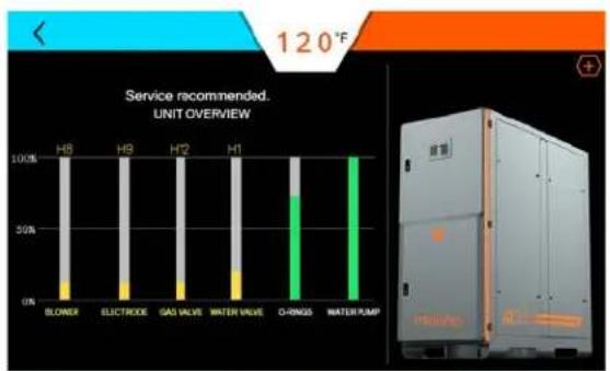

Service recommended: Order appropriate replacement part as soon as possible. To reset life, press and hold the appropriate bar and follow the prompts.

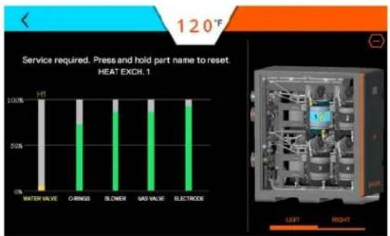
Service required: Take IMMEDIATE action when this screen appears because the part life is critical. To reset life, press and hold the appropriate bar and follow the prompts.
When a part is replaced, the screens will provide replacement part information and a screen to reset the service meter for the part being replaced.

12.8 Unit Information
This screen provides the model, software version, serial number, and a link to the contact us screen for the water heater.

12.9 More Screens

12.9.1 Wi-Fi
Intellihot Gen II water heaters are Wi-Fi capable with the factory installed IGT-SPR0085 Wi-Fi module. This feature also allows the units to be monitored and controlled from a mobile device.


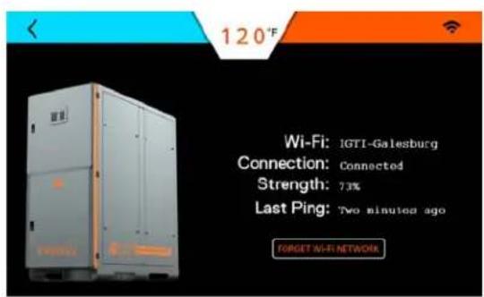
Status of Wi-Fi connection screens.
Whenever software updates are being made, the following screens will appear.

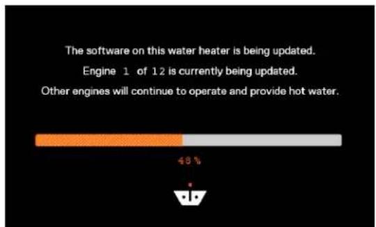

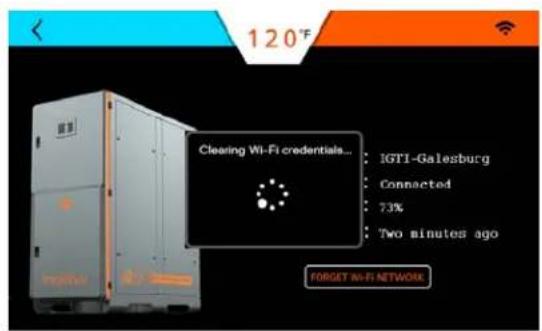

12.9.2 Error History

There are several error history screens. One screen provides an overview of the entire unit. Pressing the (+) icon provides more detailed error information.


Left and Right bank error history screens.


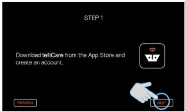
12.9.3 telliCare Service (Subscribe at Startup)
telliCare is a Wi-Fi enabled, prognostics and predictive maintenance service for Gen II water heaters. This service allows water heaters to be monitored and controlled remotely via an app on a mobile device.
On Startup:

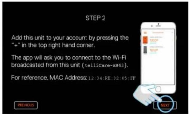
If setup is not complete:
Tap anywhere on the screen to continue.


If telliCare setup is skipped, register the unit by scanning the QR Code via the App.
Note: Each individual unit must be registered and each unit can only be registered once.
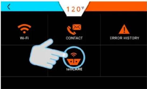
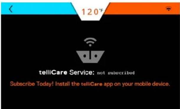
Subscribe to this service by downloading the telliCare app from iTunes App Store and following the prompts on the app.
Two status screens provide the expiration date of the service and if it is on an auto renewal schedule.


13. Connecting Multiple Units
13.1 General Information
Multiple units can be connected together to supply large demands of hot water.
The water heaters communicate through a cable connection between each water heater. The benefits of connecting the units are:
- When demand for hot water is low, fewer units will operate.
- If one unit has an error code, the others will continue to operate.
- Changing the settings (temperature, time, etc.) on one unit changes settings on all the units.
- It allows shut down of one unit for maintenance while the others continue to operate.
13.2 Installation Procedure
- Connect all the units to a gas supply pipe. Make sure the pipe is properly sized in accordance with the BTU draw and number of units being operated. Refer to "6. Gas Connection" on page 17 for additional information.
- Connect all the units to the power supply. Refer to "9. Electrical Power" on page 35 for additional information.

- Install the combustion (fresh) air intake and exhaust outlet pipes. Refer to "7. Air Intake Inlet and Exhaust Gas Outlet Pipe Connections" on page 22 for additional information.
- Install and connect the hot water lines. If an optional hot water storage tank is required, connect the hot water lines to this tank. Make sure the water pipe is properly sized in accordance with the number of units being operated.
- Install and connect the cold water lines. Make sure the water line is properly sized in accordance with the number of units being operated.
- Connect and route the condensate drain lines to a suitable discharge location. Refer to "8. Water Connections" on page 31 for additional information.
-
Do Not connect communication cables at this time.
-
Power up all the units and assign a unique number, one through four to each unit. Set the STAGING to ON.


Note: Different size floor-standing water heaters (iQ751, iQ1001, iQ1501, iQ2001, or iQ3001) can be connected. When assigning unit numbers, start with the smallest unit and progress to the largest. A maximum of two iQ3001 water heaters or three iQ2001 water can be connected.
WARNING
Before making any adjustments or connections inside the water heater cabinet, make sure the power is disconnected. Unplug the water and/or turn the circuit breaker OFF.
-
If necessary, press the Power button to turn OFF each water heater in the system and disconnect power from all the units in the system.
-
Open the side panels and locate the main circuit boards.
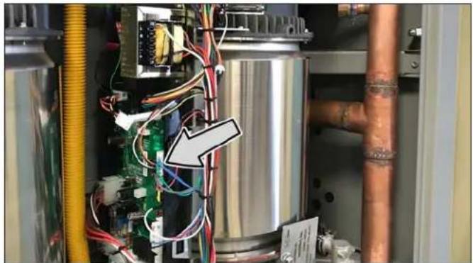
iQ2001 with Eight Circuit Boards. iQ3001 with Twelve Circuit Boards.
- Connect the included communication cable from an open jack on the circuit board in one unit to an open jack in the next unit. Repeat this step as required by the number of water heaters being connected.
- On the first water heater, locate DIP Switch 3 on circuit board 1. Position the switch in the ON position (left) as shown in the table below.
- Position all other switches on the circuit boards in the unit to the OFF position (right).
- On any water heater unit between the first and last unit, the position of all DIP SW3 switches should be in the OFF position (right).
- On the last water heater, locate DIP Switch 3 as shown in the table below.
- Once the communication cables are routed and connected and the DIP switches are correctly positioned, close and lock the front door.
- Reconnect the power and turn the water heater ON. The water heaters, should now be ready to communicate with each other and operate as a single system.
Note: Whenever a change is made to any one water heater, all the other units in the system will be automatically updated to the new settings.
13.2.1 telliCare for Multiple Units
If cascading multiple units, the Wi-Fi module on all units besides "Unit 1" in the sequence need to be disconnected to make room for cascade communication cables. Remove the attached cable at each end from the referenced jacks and set aside.

| Cascade Termination DIP Switch 3 Setting (Single Unit) | ||||||||||||
| Board Number | ||||||||||||
| Model 1 2 | 3 4 5 6 7 8 | 9 10 11 12 | ||||||||||
| iQ2001 | ON | OFF | OFF | OFF | OFF | OFF | OFF | OFF | ON | N/A | ||
| iQ3001 | ON | OFF | OFF | OFF | OFF | OFF | OFF | OFF | OFF | OFF | OFF | ON |
| Cascade Termination DIP Switch 3 Setting (Multiple Units) | ||||||||||||
| Board Number | ||||||||||||
| Model 12 | 345678 | 9101112 | ||||||||||
| iQ2001Unit 1 | ON | OFF | OFF | OFF | OFF | OFF | OFF | OFF | OFF | N/A | ||
| Unit 2 | OFF | OFF | OFF | OFF | OFF | OFF | OFF | OFF | OFF | |||
| Unit 3 | OFF | OFF | OFF | OFF | OFF | OFF | OFF | OFF | ON | |||
| iQ3001Unit 1 | ON | OFF | OFF | OFF | OFF | OFF | OFF | OFF | OFF | OFF | OFF | OFF |
| Unit 2 | OFF | OFF | OFF | OFF | OFF | OFF | OFF | OFF | OFF | OFF | OFF | ON |
14. Maintenance
14.1 Air Filter
14.1.1 Inspection
Check the filter every six months for dirt and dust build-up. Clean and re-oil the filter annually. If the filter is dirty, follow the cleaning procedure.
Note: The air filter is manufactured by K&N. Contact K&N at 800-858-3333 or online at www.knfilters.com for the necessary supplies to clean the filter.
- Loosen the band clamp and remove the air filter.
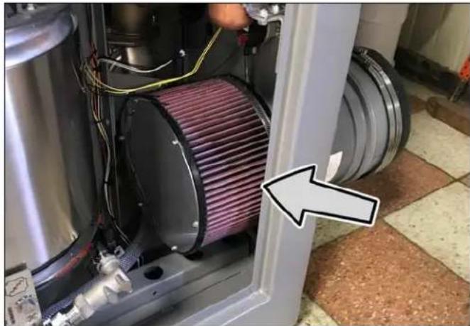
- Inspect the inside of the filter for dirt and dust build-up. Clean the filter, if needed.
- After inspection and/or cleaning, replace the air filter and snugly tighten the band clamp.
14.1.2 Cleaning Procedure
- Liberally spray K&N Air Filter Cleaner and Degreaser (99-0606) onto both sides of filter and allow to soak for 10 minutes to loosen the dirt. Do not allow cleaner to dry on air filter.
NOTICE
K&N Air Filter Cleaner is the only cleaner formulated to safely clean K&N air filters with cotton media. The use of any other cleaning solution could damage the cotton material.
- Rinse the air filter with cool low-pressure water applied from the outside inward in order to flush the dirt out of the filter. Continue to rinse the filter until all traces of cleaner are gone. It may be necessary to repeat Steps 1 and 2.
- After rinsing, gently shake off the excess water and air dry the filter.
NOTICE
Do not use compressed air to dry the filter. Do not apply oil to the filter until it is completely dry.
- Spray K&N Aerosol Air Filter Oil (99-0504) evenly along the crown of each pleat holding nozzle about 3" away. Allow oil to wick for approximately 20 minutes. Touch up any light areas on either side of the filter until there is a uniform red color at all areas.
14.2 Maintenance-Free Circulation Pumps
The circulation pumps are maintenance-free and therefore does not require any servicing. The only adjustment is the speed setting, which must be set to Speed 3 (III).
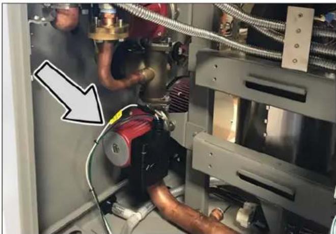
14.3 Heat Engine Locations
Use the following diagrams to identify the location of the heat engines.
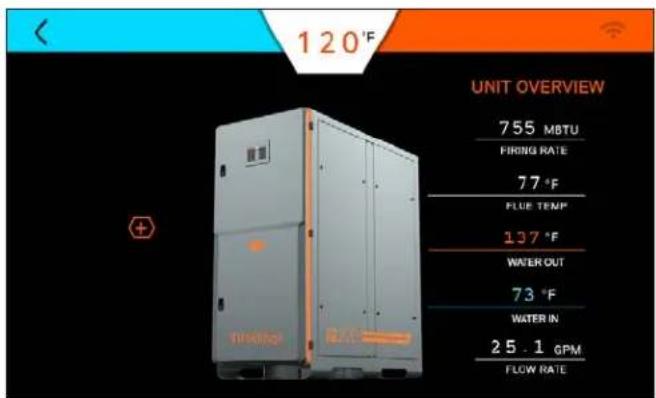

iQ2001 Left status.

iQ2001 Right status.

iQ3001 Right status.

iQ3001 Left status.
15. Wiring Diagrams and Troubleshooting
15.1 Operational Flow Chart
![graph TD A["Wait"] --> B{Is Flow On} B -->|Yes| C["Energize Ignition Module"] B -->|No| D{Is Temp. Within Limits} D -->|Yes| E["De-energize Ignition Module"] D -->|No| F["Maintain Temperature Module"] C --> G{Successful Ignition} G -->|Yes| H["Set Modulation"] G -->|No| I["Error Handler"] H --> J{Sa…](/content/2026/05/955810/images/1946d83a42839440bb60f8eeb211eff10f4a7b6ca2fd45442a28eff734a99723.jpg)
IH-56
15.2 Complete Wiring Diagram (all models)

15.3 Control Board Wiring Diagram (iQ2001)
![graph TD A["CONTROL MODULE 1"] --> B["COMUNICATION CABLE"] B --> C["DISPLAY"] D["PUMP"] --> E["FUSE"] E --> F["GN'YL RN BL"] F --> G["LOAD BK WT GN LINE"] G --> H["POWER SWITCH (LOWER)"] H --> I["LINE"] I --> J["CONTROL MODULE 2"] K["CONTROL MODULE 5"] --> L["COMMUNICATION CABLE"] L --> M["CONJECUTR…](/content/2026/05/955810/images/97118d203f6dc89543a92fd330e7c23aafe70d3aa9c29209c0a23d66b5644a56.jpg)
15.4 Control Board Wiring Diagram (iQ3001)
![graph TD A["CONTROL MODULE 1"] --> B["DISPLAY"] C["CONTROL MODULE 2"] --> D["COMMUNICATION CABLE CABLE"] E["CONTROL MODULE 3"] --> F["COMMUNICATION CABLE CABLE"] G["PUMP"] --> H["GN-YL FUSE"] I["CONTROL MODULE 4"] --> J["COMMUNICATION CABLE"] K["CONTROL MODULE 5"] --> L["COMMUNICATION CABLE"] M["CON…](/content/2026/05/955810/images/3b331c35124f62409a9978b9bb99d8193d4a800c63a27fb73a38ee888cbee381.jpg)
15.5 Troubleshooting Guide
| Description Possible Cause | Remedy | |
BlowerSpeed Fault | Blower noisy / impeller jammed.Disconnected signal wire.Wiring faulty. | Inspect blower / impeller. Clean and remove any obstructions.Check PWN signal. Check for loose wires / pins, and repair.If the problem persists, turn control panel OFF, shut gas valve, disconnect power from unit, and contact an authorized service technician. |
IgniterIgnition Failure | Water over-heat switch tripped.Faulty DSI, faulty igniter wire, faulty ignition connection, faulty PCB, bad igniter.Low gas pressure.Wiring faulty. | Check pump, check cross-over solenoid. Electrical noise (DSI).Replace part.Adjust gas pressure at regulator, check / increase size of gas line, check for gas line blockage.If the problem persists, turn control panel OFF, shut gas valve, disconnect power from unit, and contact an authorized service technician. |
Open SensorsInlet / Outlet Sensors  | Unplugged connectors.Faulty sensor wiring.Faulty sensor.Heat engine water outlet temperature sensor.Flue temperature sensor.Inlet water temperature sensor.Faulty controller. | Check connectors and ensure they are securely connectedCheck for nicked or broken sensor wiring or connectors. Also check for corroded or wet connectorsMeasure resistance of sensor at connector (18 kΩ at 50°F, 10 kΩ at 77°F, 3 kΩ at 140°F).Replace controller. |
Faulty SensorsInlet / Outlet Sensors  | Faulty sensor wiring or faulty sensor.Inlet water temperature sensor.Heat engine water outlet temperature sensor.Faulty controller. | Check for nicked or broken sensor wiring or connectors. Also check for corroded or wet connectors.Measure resistance of sensor at connector (18 kΩ at 50°F, 10 kΩ at 77°F, 3 kΩ at 140°F).Replace controller |
Heat EngineOutlet temperature exceeded set limit | Flow rate changes excessive.Faulty sensor wiring.Faulty sensor.Faulty controller. | Ensure the water flow rate does not change faster than 2 GPM every 5 seconds.Check for nicked or broken sensor wiring or connectors. Also check for corroded or wet connectors.Measure resistance of sensor at connector (18 kΩ at 50°F, 10 kΩ at 77°F, 3 kΩ at 140°F).Replace controller. |
FlueTemperature Exceeded Set Limit | Incorrect vent set up.High inlet temperature.Faulty sensor wiring.Faulty sensor.Faulty controller. | If vent pipe material is CPVC or polypropylene, ensure that CPVC is selected in the vent material screen.Ensure inlet temperature is lower than 150°F if vent pipe material is PVC or lower than 190°F if vent pipe material is CPVC or polypropylene.Check for nicked or broken sensor wiring and connectors. Also check for corroded or wet connectors.Measure resistance of sensor at connector (18 kΩ at 50°F, 10 kΩ at 77°F, 3 kΩ at 140°F).Replace controller |
Blocked Flue Fault(c). | Backed up condensate.Wiring loose (switch open). | Check exhaust termination. Check exhaust connection at water heater. Install screens to prevent blockage.Check slope of drain. Check for double loops, air locks, or debris in loop.Check wiring. |
Flue sensor | Unplugged connectors.Faulty sensor wiring.Faulty sensor.Flue temperature sensor.Inlet water temperature sensor.Faulty controller. | Check connectors and ensure they are securely connectedCheck for nicked or broken sensor wiring or connectors. Also check for corroded or wet connectorsMeasure resistance of sensor at connector (18 kΩ at 50°F, 10 kΩ at 77°F, 3 kΩ at 140°F).Replace controller. |
CascadingFault Alert Alert | Loss of communication between units. | Check for broken or nicked communication cable or loose connector.Ensure that the communication cable is not bundled or tied to any high voltage lines.Ensure dip switch (SW3) is ON in first and last units and OFF in all other units.Ensure each unit numbering is unique. |
Water Valve | Faulty sensor wiring.Water valve clogged or damaged. | Check for nicked or broken sensor wiring or connectors. Also check for corroded or wet connectors.Replace water valve. |
| Description Possible Cause Remedy | ||
Pump   | ·Faulty pump wiring.·Pump fuse blown.·Faulty pump.·Faulty controller. | ·Check for nicked or broken sensor wiring or connectors. Also check for corroded or wet connectors.·Replace fuse (5 Amp)·Replace pump.·Replace controller. |
Fuel Type | ·DIP switches mismatched (SW1) · | Check switches on all boards to make sure they are all set to the same gas type. |
Software  | ·Incorrect settings.·Incompatible settings.·Incorrect software version.·Faulty wiring. | ·Review and correct settings.·Review and correct settings.·Update software version.·Check for nicked or broken sensor wiring or connectors. Also check for corroded or wet connectors. |
Air Filter   | ·Blocked inlet.·Over six months in service·Dirty or damaged filter. | ·Remove blockage and install screens to prevent future blockage·Remove and inspect filter. Clean or replace as needed. |
Manifold Sensors      | Blocked inlet.Dirty or damaged filter.Unplugged connectors.Faulty sensor wiring.Faulty sensor.Faulty controller. | .Remove blockage and install screens to prevent future blockage.Remove and inspect filter. Clean or replace as needed.Check connectors and ensure they are securely connectedCheck for nicked or broken sensor wiring or connectors. Also check for corroded or wet connectorsMeasure resistance of sensor at connector (18 kΩ at 50°F, 10 kΩ at 77°F, 3 kΩ at 140°F).Replace controller. |
System Alert | A system alert is present (main menu screen).Malfunction of monitored part or system. | Refer to the remedy for indicated part or system. |
Fault | A fault or error is present (main menu screen).Malfunction of monitored part or system. | Refer to the remedy for indicated part or system. |
| Description Possible Cause | Remedy | |
Alert / Error / Fault   | · An alert, fault, or error is present(active screen).· Malfunction of monitored part or system. | · Refer to the remedy for indicated part or system. |
Alive     | · Shows status of water heater.· Sleep mode.· Sleep mode passcode protected.· Indicates a service problem exists within the monitored parts.· Indicates an alert exists within the monitored systems.· Indicates a fault exists within the monitored parts or system. | · Touch display screen to awake.· Touch display screen to awake and enter passcode.· Refer to the remedy for indicated part or system.· Refer to the remedy for indicated part or system.· Refer to the remedy for indicated part or system. |
16. Requirements for State of Massachusetts
16.1 Notice Before Installation
This appliance must be installed by a licensed plumber or gas fitter in accordance with the Massachusetts Plumbing and Fuel Gas Code 248 CMR Sections 2.00 and 5.00.
IMPORTANT: In the State of Massachusetts (248 CMR 4.00 & 5.00)
For all side wall horizontally vented gas fueled equipment installed in every dwelling, building or structure used in whole or in part for residential purposes, including those owned or operated by the Commonwealth and where the side wall exhaust vent termination is less than seven (7) feet above finished grade in the area of the venting, including but not limited to decks and porches, the following requirements shall be satisfied:
1. INSTALLATION OF CARBON MONOXIDE DETECTORS.
At the time of installation of the side wall horizontal vented gas fueled equipment, the installing plumber or gasfitter shall observe that a hard wired carbon monoxide detector with an alarm and battery backup is installed on the floor level where the gas equipment is to be installed. In addition, the installing plumber or gasfitter shall observe that a battery operated or hard wired carbon monoxide detector with an alarm is installed on each additional level of the dwelling, building, or structure served by the side wall horizontal vented gas fueled equipment. It shall be the responsibility of the property owner to secure the services of qualified licensed professionals for the installation of hard wired carbon monoxide detectors.
a. In the event that the side wall horizontally vented gas fueled equipment is installed in a crawl space or an attic, the hard wired carbon monoxide detector with alarm and battery back-up may be installed on the next adjacent floor level.
b. In the event that the requirements of this subdivision cannot be met at the time of completion of installation, the owner shall have a period of thirty (30) days to comply with the above requirements; provided, however, that during said thirty (30) day period, a battery operated carbon monoxide detector with an alarm shall be installed.
2. APPROVED CARBON MONOXIDE DETECTORS.
Each carbon monoxide detector, as required in accordance with the above provisions, shall comply with NFPA 720 and be ANSI/UL 2034 listed and IAS certified.
3. SIGNAGE.
A metal or plastic identification plate shall be permanently mounted to the exterior of the building at a minimum height of eight (8) feet above grade directly in line with the exhaust vent terminal for the horizontally vented gas fueled heating appliance or equipment. The sign shall read, in print size no less than one-half (1/2) inch in size, "GAS VENT DIRECTLY BELOW. KEEP CLEAR OF ALL OBSTRUCTIONS".
4. INSPECTION.
The state or local gas inspector of the side wall horizontally vented gas fueled equipment shall not approve the installation unless, upon inspection, the inspector observes carbon monoxide detectors and signage installed in accordance with the provisions of 248 CMR 5.08(2)(a)1 through 4.
17. Warranty
17.1 Warranty
General
This unit is warranted by Intellihot Inc., and covers defects in materials and workmanship, subject to the applicable time periods and terms below. The warranty effective start date begins on the date of commissioning.
This warranty is extended to the original purchaser and any subsequent owner at the original install location, and applies only when properly installed by a licensed contractor and operated in accordance with the instruction manuals. This warranty is limited to repairs or replacement of parts, at Intellihot's option that are proven to be defective under normal use and connected only to potable water systems.
Warranty Period
Commercial Domestic Hot Water (DHW) Warranty: Heat Engine coil - 10 years, Other Parts - 2 years.
Heat Engine Coil
The warranty period for a heat engine coil failure, when installed in a Commercial DHW application is ten (10) years from the effective start date.
All Other Parts and Components
The warranty period for any original parts (excluding the heat engine coil) against failure, is two (2) years from the effective start date. A replacement part will be warranted for the unexpired term of the original warranty. Defective parts submitted may not be returned. No returns will be accepted without prior authorization from Intellihot.
Definition of Potable water
Potable water is defined as drinkable water supplied from utility or well water in compliance with EPA secondary maximum contaminant levels (40 CFR part 143.3) as shown in the table.
| Contaminant Level | |
| Aluminum 0.05 to 0.2 mg/l | |
| Chloride 250 mg/l | |
| Color 15 color units | |
| Copper 1.0 mg/l | |
| Corrosivity Non-corrosive | |
| Fluoride 2.0 mg/l | |
| Foaming Agents 0.5 mg/l | |
| Iron 0.3 mg/l | |
| Manganese | 0.05 mg/l |
| Odor | 3 threshold odor number |
| pH | 6.5-8.5 mg/l |
| Silver | 0.1 mg/l |
| Sulfate | 250 mg/l |
| Total dissolved solids (TDS) | 500 mg/l |
| Zinc | 5 mg/l |
Shipping Costs
If a replacement part is supplied under the terms of this warranty, Intellihot will provide ground service delivery for the part free of charge. Any expedited shipping expense will be paid by the customer.
Water Hardness Criteria
This warranty applies only when the water quality and supply meets the parameters outlined in the table below.
To use the table, locate the desired unit setpoint temperature on the left side of the table. Then locate the incoming water pressure across the top. The corresponding value in the table is the maximum allowable hardness in grains per gallon (gpg).
| Maximum Allowable Hardness (grains per gallon, gpg) | ||||||
| Unit Setpoint(°F) | Incoming Water Pressure (psi) | |||||
| 30 | 40 | 50 | 60 | 80 | 100 | |
| 100-120° | 8 | 15 | 20 | 25 | 30 | 30 |
| 120-140° | 5 | 11 | 15 | 20 | 27 | 30 |
| 140-160° | 4 | 5 | 11 | 13 | 18 | 20 |
| 160-190° | 3 | 4 | 10 | 12 | 15 | 17 |
Not Covered by this Warranty
This warranty does not cover failures or problems due to:
- Failure to install in accordance with applicable building codes, ordinances, normal plumbing, or electrical trade practices.
- Improper installation, improper use, improper maintenance, improperly made replacements or repairs, accidents or abuse.
- Sediment deposits, fire, flood, lightning, freezing, and acts of God, or any causes other than defects in materials and workmanship.
- The unit is installed without consideration for an adequate drain to accommodate leaks,
- The unit installed where the leakage could result in damage to the area adjacent to the water heater or to the lower floors of the building.
- Damages due to improper/inadequate water hardness treatment or damages from scale formation due to water hardness.
- Water heater's usage flow rate required a water hammer arrestor, but water hammer arrestor not installed.
- Electrical failures due to Inadequately sized electrical breaker or inadequately sized wire
• Not performing recommended maintenance.
- Not properly electrically grounding the unit or not following the electrical grounding requirements.
This warranty will be void and have no effect if:
- The unit is modified or altered in any way.
- Appliance(s) or equipment are attached to the unit that have not been approved by Intellihot Inc.
- If the unit is used exclusively as a booster heater for a commercial dishwasher, or if the water from a reverse osmosis or deionized process is run directly through the unit.
- The serial number is altered, defaced, or discarded.
Warranty Limitations
This warranty applies only when the unit is used in the United States or Canada. Except for the limited warranties provided above, Intellihot Inc. disclaims any and all other warranties, including but not limited to warranties of merchantability and fitness for a particular purpose; provided however, that implied warranties of merchantability and fitness for a particular purpose are not disclaimed during the 1-year period from the effective date. Intellihot shall not be liable for indirect, special, incidental, consequential, or other similar damages, including lost profits, arising from or relating to the unit. This warranty gives you specific legal rights, and you may also have other rights which vary from state to state.
How to Make a Claim
The warranty claim can be submitted online at https://www.intellihot.com/warranty-claim/
or
by calling (877) 835-1705. Proof of purchase in the form of a dated sales receipt or warranty registration should be included with your claim. The product owner should submit the warranty claim directly to Intellihot at the following address:
Intellihot Inc.
Attn: Warranty Claims
2900 W. Main St.
Galesburg, IL 61401
All parts claimed to be defective may be requested to be returned to Intellihot for examination prior to full claim settlement. Please include the following information on your warranty claim:
- Model number and serial number of the unit.
- Date of original purchase.
- Owner's name and address.
- A description of the problem with the part and unit.
NOTES
18. Product Warranty
18.1 Warranty
To register via the telliCare app, refer to "12.9.3 telliCare Service (Subscribe at Startup)" on page 51.
Warranty Registration Intellihot Inc. 2900 W. Main Street Galesburg, IL 61401
Or fill out the information in the form below and mail to the following address:
Make a copy or cut here to remove page.
Model:
Serial Numbers (up to 12):
Owner Information: Name: ____ Address: ____ City, State, Postal Code: ____ Phone Number: ____
Dealer Information: Sold By: ____ Address: ____ City, State, Postal Code: ____ Phone Number: ____

Endless water. Zero waste. TM


Intellihot
12-2022
Par1#:IGT-MNL0044


- WHAT TO DO IF YOU SMELL GAS
- AVERTISSEMENT
- THANK YOU FOR PURCHASING THIS INTELLIHOT UNIT
- TABLE OF CONTENTS
- GENERAL INFORMATION
- SAFETY
- TECHNICAL SPECIFICATIONS
- QUICK REFERENCE INSTALLATION GUIDE
- PREPARATION BEFORE INSTALLATION
- GAS CONNECTION
- AIR INTAKE INLET AND EXHAUST GAS OUTLET PIPE CONNECTIONS
- WATER CONNECTIONS
- ELECTRICAL POWER
- ADJUSTING CO2 LEVEL
- NATURAL GAS TO PROPANE CONVERSION
- OPERATION
- CONNECTING MULTIPLE UNITS
- MAINTENANCE
- WIRING DIAGRAMS AND TROUBLESHOOTING
- REQUIREMENTS FOR STATE OF MASSACHUSETTS
- WARRANTY
- PRODUCT WARRANTY
- WARNING
- DANGER
- CONTACT INFORMATION
- 1.1 ITEMS SHIPPED WITH WATER HEATER
- 1.2 SERIAL NUMBER LOCATIONS
- 2.1 SAFETY SIGNAL WORDS
- CAUTION
- NOTICE
- SAFETY INSTRUCTIONS
- 2.2 INSTALLATION WARNINGS
- INSTRUCTIONS
- 3.2 HIGH ELEVATION INSTALLATIONS
- 3.3 CLEARANCE REQUIREMENTS
- 3.4 CONNECTION SPECIFICATIONS
- 3.5 EXHAUST GAS STANDARDS
- 3.6 OVERALL DIMENSIONS
- 3.7 CONFIGURATION OPTIONS
- 4.1 INSTALL THE WATER HEATER
- 4.2 PRE-STARTUP INSTRUCTIONS
- 5.1 SELECTING AN INDOOR INSTALLATION SITE
- 5.2 SELECTING AN OUTDOOR INSTALLATION SITE
- FIRE AND/OR EXPLOSION HAZARD
- 6.1 QUICK REFERENCE INSTALLATION INSTRUCTIONS
- 6.2 FUEL SOURCE
- 6.3 GAS PRESSURE REQUIREMENTS
- 6.4 GAS PRESSURE REGULATOR
- 6.4.1 VENTING OF GAS SUPPLY REGULATORS
- 6.5 LENGTH OF GAS SUPPLY LINE
- 6.6 GAS PIPING MATERIAL
- 6.7 DETERMINE CORRECT GAS PIPE DIAMETER
- 6.8 GAS PIPE DRIP LEG AND SHUT-OFF VALVE
- 6.9 CONNECTING GAS LINE TO UNIT
- 6.10 GAS PIPE SIZING TABLES
- BREATHING HAZARD CARBON MONOXIDE GAS
- 7.1 QUICK REFERENCE INSTALLATION GUIDE
- 7.2 TYPICAL SINGLE UNIT AIR INTAKE INLET AND EXHAUST GAS OUTLET PIPE INSTALLATION
- 7.3 TWO PIPE VENT SYSTEM (DIRECT VENT)
- 7.3.1 SINGLE UNIT CONFIGURATIONS
- 7.3.2 MULTIPLE UNITS CONFIGURATIONS
- 7.3.3 SIDE WALL AIR INTAKE INLET AND EXHAUST GAS OUTLET PIPE TERMINATION
- 7.3.4 ROOF AIR INTAKE INLET AND EXHAUST GAS OUTLET PIPE TERMINATION
- 7.4 SINGLE PIPE VENTING SYSTEM (POWER VENT)
- 7.4.1 SINGLE UNIT
- 7.4.2 MULTIPLE UNITS
- 7.5 COMBUSTION AIR REQUIREMENTS
- 7.6 INTAKE AIR INLET AND EXHAUST GAS OUTLET PIPE DIAMETER AND LENGTH
- 7.7 VENTING CLEARANCE SPECIFICATIONS
- 7.8 EXHAUST GAS OUTLET PIPE MATERIALS
- 7.9 AIR INTAKE INLET PIPE VENT MATERIALS
- 7.10 RECOMMENDED EXHAUST GAS OUTLET PIPE TRANSITIONS
- 8.1 QUICK REFERENCE INSTALLATION INSTRUCTIONS
- 8.2 HOT WATER CONNECTION
- DO NOT INSULATE THE PRESSURE RELIEF VALVE
- 8.3 COLD WATER CONNECTION
- 8.4 CONDENSATE DRAIN LINE
- 9.1 ELECTRICAL RECOMMENDATIONS
- 9.2 CONNECTION INSTRUCTIONS
- 10.1 GENERAL INFORMATION
- 10.2 ADJUSTMENT PROCEDURE
- 11.1 GENERAL INFORMATION
- 11.2 CONVERSION PROCEDURE
- 12.2 TURNING WATER HEATER ON AND OFF
- 12.4 ADJUSTING THE WATER TEMPERATURE
- 12.5 SECURITY
- 12.5.1 SETTING PASSCODE PROTECTION
- 12.5.3 FORGOT PASSCODE
- 12.6 INTOUCH
- 12.7 LIFE SCREEN
- 12.8 UNIT INFORMATION
- 12.9.1 WI-FI
- 12.9.3 TELLICARE SERVICE (SUBSCRIBE AT STARTUP)
- 13.1 GENERAL INFORMATION
- 13.2 INSTALLATION PROCEDURE
- 13.2.1 TELLICARE FOR MULTIPLE UNITS
- 14.1 AIR FILTER
- 14.1.1 INSPECTION
- 14.1.2 CLEANING PROCEDURE
- 14.2 MAINTENANCE-FREE CIRCULATION PUMPS
- 14.3 HEAT ENGINE LOCATIONS
- 15.1 OPERATIONAL FLOW CHART
- 15.5 TROUBLESHOOTING GUIDE
- 16.1 NOTICE BEFORE INSTALLATION
- INSTALLATION OF CARBON MONOXIDE DETECTORS
- APPROVED CARBON MONOXIDE DETECTORS
- SIGNAGE
- INSPECTION
- 17.1 WARRANTY
- GENERAL
- WARRANTY PERIOD
- HEAT ENGINE COIL
- ALL OTHER PARTS AND COMPONENTS
- DEFINITION OF POTABLE WATER
- SHIPPING COSTS
- WATER HARDNESS CRITERIA
- NOT COVERED BY THIS WARRANTY
- WARRANTY LIMITATIONS
- HOW TO MAKE A CLAIM
- NOTES
- 18.1 WARRANTY
- INTELLIHOT
Brand : Intellihot
Model : iQ2001 Gen II
Category : Water heater