
EK 300 IEM G2 - Wireless in-ear monitoring system SENNHEISER - Free user manual and instructions
Find the device manual for free EK 300 IEM G2 SENNHEISER in PDF.

| Product Type | Wireless transmission system for in-ear monitoring |
| Brand | Sennheiser |
| Model | EK 300 IEM G2 |
| Category | Portable receiver for in-ear monitoring |
| Frequency band | 626 to 662 MHz (UHF) |
| Number of channels | 16 preset channels |
| Power supply | 2 AA batteries (1.5 V) or NiMH rechargeable batteries |
| Battery life | Approximately 8 hours with alkaline batteries |
| Dimensions (W x H x D) | 82 x 65 x 24 mm |
| Weight | Approximately 100 g (without batteries) |
| Audio output | 3.5 mm stereo mini-jack |
| Audio output power | 30 mW (at 32 Ω) |
| Signal-to-noise ratio | > 85 dB (A) |
| Total harmonic distortion | < 0.9% |
| Antenna | Fixed integrated antenna |
| Squelch function | Yes, adjustable |
| Display | Backlit LCD screen |
| Operating temperature | -10°C to +55°C |
| Maintenance and cleaning | Clean with a soft, dry cloth. Do not use solvents. |
| Safety | Follow local regulations regarding radio frequencies. |
| Spare parts and repairability | Standard batteries available. Repair by an authorized Sennheiser service center. |
| Warranty | 24 months (excluding batteries) |
| General information | Compliant with European directives R&TTE 1999/5/EC. |
Frequently Asked Questions - EK 300 IEM G2 SENNHEISER
User questions about EK 300 IEM G2 SENNHEISER
0 question about this device. Answer the ones you know or ask your own.
Ask a new question about this device
Download the instructions for your Wireless in-ear monitoring system in PDF format for free! Find your manual EK 300 IEM G2 - SENNHEISER and take your electronic device back in hand. On this page are published all the documents necessary for the use of your device. EK 300 IEM G2 by SENNHEISER.
USER MANUAL EK 300 IEM G2 SENNHEISER
Instructions for use

natural_image
Illustration of a black cable with two connectors and a connector pin, no text or symbols present.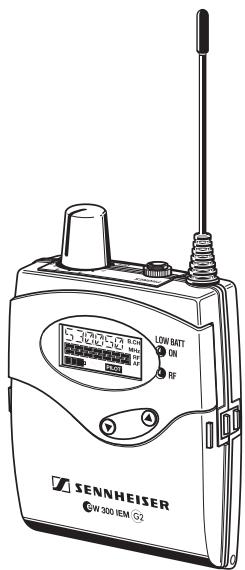
Thank you for choosing Sennheiser!
We have designed this product to give you reliable operation over many years. Over half a century of accumulated expertise in the design and manufacture of high-quality electro-acoustic equipment have made Sennheiser a world-leading company in this field.
Please take a few moments to read these instructions carefully, as we want you to enjoy your new Sennheiser products quickly and to the fullest.
Contents
The ew 300 IEM G2 system 42
The channel bank system 42
Safety instructions 43
System components 43
Overview of operating controls 44
SR 300 IEM G2 stereo transmitter 44
EK 300 IEM G2 stereo receiver 45
Indications and displays on the transmitter 46
Indications and displays on the receiver 46
Preparing the components for use 48
SR 300 IEM G2 stereo transmitter 48
EK 300 IEM G2 stereo receiver .... 51
Using the components 52
Switching the components on/off 52
Adjusting the volume 52
Adjusting the balance 53
Activating/deactivating the lock mode 53
Attaching the receiver to clothing 53
The operating menu 54
The buttons 54
Overview of menus 55
Working with the operating menu 55
Operating menu of the stereo transmitter 57
Operating menu of the stereo receiver 59
Adjustment tips for the operating menu 62
Switching between channel banks 62
Switching between the channels in a channel bank 62
Selecting the frequencies to be stored
in the channel bank "U" 62
Scanning the channel banks for free channels
(receiver only) 62
Multi-channel operation 63
Adjusting the squelch threshold (receiver only) 63
Stereo/FOCUS selection (receiver only) 64
Limiting the volume at the headphone output (receiver only) 64
Activating/deactivating the frequency boost (receiver only) 64
Adjusting the sensitivity (transmitter only) 64
Selecting the standard display 65
Entering a name 65
Loading the factory-preset default settings 66
Activating/deactivating the pilot tone evaluation (receiver only) 66
Adjusting the contrast of the graphic display (transmitter only) 66
Stereo/Mono selection (transmitter only) 66
Activating/deactivating the lock mode 67
Exiting the operating menu 67
Troubleshooting 68
Error checklist 68
Recommendations and tips 69
Care and maintenance 69
Additional information 70
HDX noise reduction 70
Wireless transmission systems 70
Squelch 71
Specifications 72
Connector assignment 73
Accessories 73
The ew 300 IEM G2 system
With the Sennheiser evolution wireless in-ear monitoring system ew 300 IEM G2 (suitable for both stage and broadcast use), musicians, video and sound amateurs, reporters/broadcasters, etc. can directly monitor the received sound signals without troublesome cables or monitor speakers being required. In addition, the system can also be used for any application where talkback signals are to be transmitted.
The evolution wireless in-ear monitoring system ew 300 IEM G2 is a high-quality state-of-the-art RF transmission systems with a high level of operational reliability and ease of use. Transmitter and receiver permit wireless transmission with studio-quality sound. The excellent transmission reliability of the ew 300 IEM G2 system is based on the use of
- further optimized PLL synthesizer and microprocessor technology,
• the HDX noise reduction system, - the pilot tone squelch control (during stereo operation),
• and the scan function for scanning the channel banks for free channels.
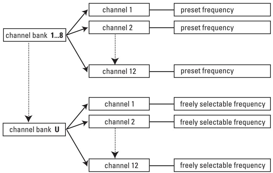
The channel bank system
The ew 300 IEM G2 system is available in five UHF frequency ranges with 1440 transmission/receiving frequencies per frequency range. Please note: Frequency usage is different for each country. Your Sennheiser agent will have all the necessary details on the available legal frequencies for your area.
Range A: 518 to 554 MHz
Range B: 626 to 662 MHz
Range C: 740 to 776 MHz
Range D: 786 to 822 MHz
Range E: 830 to 866 MHz
Transmitter and receiver have nine channel banks with up to 12 switchable channels each.
flowchart
graph TD
    A["channel bank 1...8"] --> B—including Channel 1 (preset frequency)]
    A --> C—including Channel 2 (preset frequency)]
    A --> D—including Channel 12 (preset frequency)]
    A --> E—including Channel 1 (freely selectable frequency)]
    A --> F—including Channel 2 (freely selectable frequency)]
    A --> G—including Channel 12 (freely selectable frequency)]
    H["channel bank U"] --> I—including Channel 1 (preset frequency)]
    H --> J—including Channel 2 (preset frequency)]
    H --> K—including Channel 12 (preset frequency)]
The channel banks “1” to “8” have switchable channels that are factory-preset to a transmission/receiving frequency (see enclosed frequency table). These transmission/receiving frequencies cannot be changed but have been preset so that e.g. country-specific regulations on frequency usage are taken
into account. The channel bank "U" (user bank) has up to 12 switchable channels to store your selection out of 1440 transmission/receiving frequencies that are freely selectable within the preset frequency range.
An advantage of the factory-preset frequencies is that
- the system is ready for immediate use after switch-on,
- several in-ear monitoring systems can be operated simultaneously on the preset channels without causing intermodulation interference.
Safety instructions
Never open electronic units! If units are opened by customers in breach of this instruction, the warranty becomes null and void.
Keep the units away from central heating radiators and electric heaters. Never expose them to direct sunlight.
Use the units in dry rooms only.
Use a damp cloth for cleaning the units. Do not use any cleansing agents or solvents.
Attention! High Volume!
This is a professional transmission system. Commercial use is subject to the rules and regulations of the trade association responsible. Sennheiser, as the manufacturer, is therefore obliged to expressly point out possible health risks arising from use.
This system is capable of producing sound pressure exceeding 85 dB(A). 85 dB(A) is the sound pressure corresponding to the maximum permissible volume which is by law (in some countries) allowed to affect your hearing for the duration of a working day. It is used as a basis according to the specifications of industrial medicine. Higher volumes or longer durations can damage your hearing. At higher volumes, the duration must be shortened in order to prevent damage. The following are sure signs that you have been subjected to excessive noise for too long a time:
- You can hear ringing or whistling sounds in your ears.
- You have the impression (even for a short time only) that you can no longer hear high notes.
System components
The system consists of:
• 1 EK 300 IEM G2 stereo receiver
• 1 SR 300 IEM G2 stereo transmitter
- 2 batteries
• 1 telescopic antenna for SR 300 IEM G2
• 1 NT 2-1 mains unit
• IE 3 in-ear headphones
- Instructions for use

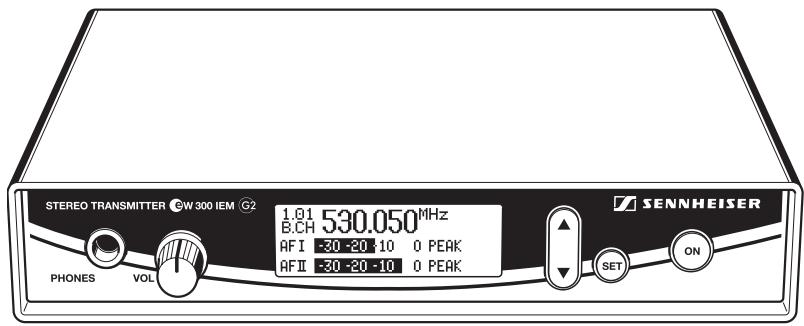
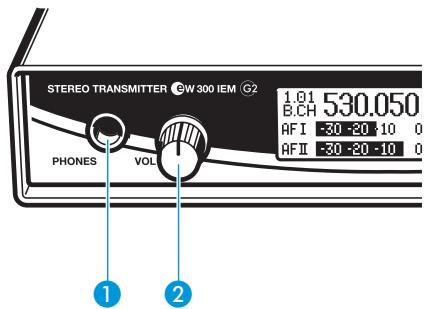
Overview of operating controls
SR 300 IEM G2 stereo transmitter
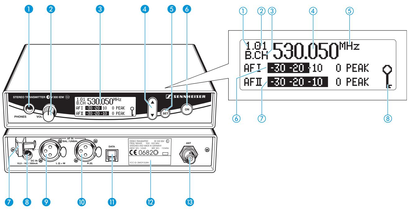
Operating controls
1 Headphone output (PHONES), 14 " (6.3 mm) jack socket
2 Headphone volume control (VOL)
3 Graphic display, backlit
4 ▼/▲ rocker button, backlit
5 SET button, backlit
6 ON button, backlit (serves as the ESC (cancel) key in the operating menu)
7 Cable grip for power supply DC cable
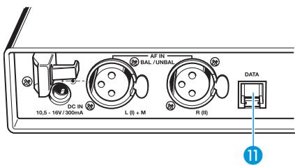
8 DC socket for connection of mains unit (DC IN)
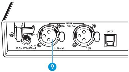
9 Audio input (AF IN BAL/UNBAL), XLR-3F socket (left and MONO)
10 Audio input (AF IN BAL/UNBAL), XLR-3F socket (right)
11 Service interface (DATA)
12 Type plate
13 Antenna output (ANT), BNC socket
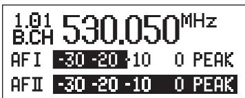
Graphic display panel
① Display for the current channel bank "1...8, U"
② Display for the current channel number "1...12"
③ "B.CH" – abbreviation for channel bank and channel number
④ Alphanumeric display
⑤ "MHz" – appears when the frequency is displayed
⑥ Level display for audio signal "AF I" (left and MONO), with "PEAK" warning
⑦ Level display for audio signal "AF II" (right), with "PEAK" warning
⑧ Lock mode icon (lock mode is activated)
Note:
For further illustrations and examples of the different standard displays, please refer to the section "Selecting the standard display" on page 65.
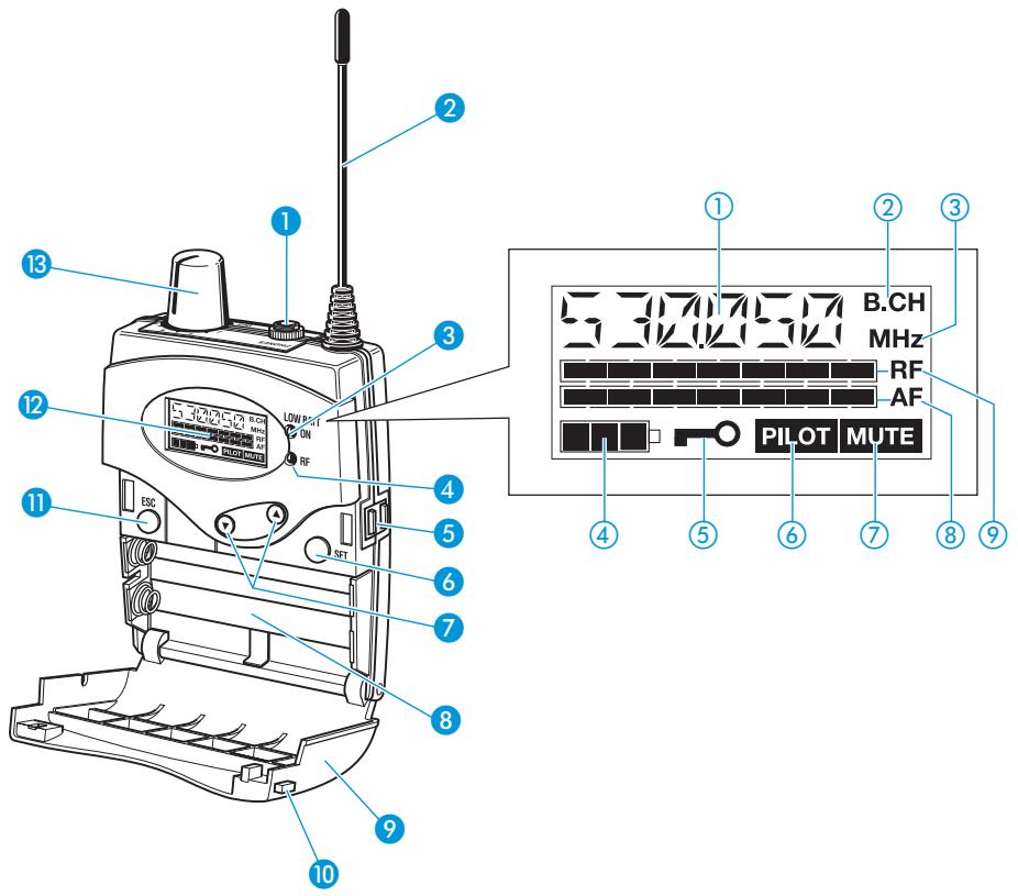
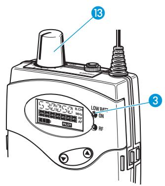
Operating controls
1 Headphone output (PHONES), 3.5 mm jack socket
2 Antenna
3 Red LED for operation and battery status indication (ON/LOW BAT)
4 Green LED for RF signal indication (RF)
5 SET button
6 ▼/▲ rocker button (DOWN/UP)
7 Battery compartment
8 Battery compartment cover
9 Unlocking button
10 ESC button
11 LC display
12 On/off/volume control
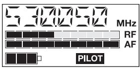
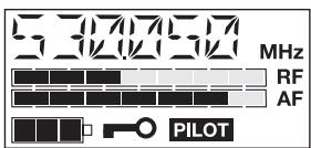
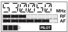
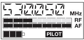
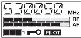
LC display panel
① Alphanumeric display
② "B.CH" – appears when the channel bank and the channel number are displayed
③ “MHz” – appears when the frequency is displayed
④ 4-step battery status display
⑤ Lock mode icon (lock mode is activated)
⑥ "PILOT" display (pilot tone evaluation is activated)
⑦ "MUTE" display (audio output is muted)
⑧ 7-step level display for received audio signal "AF"
⑨ 7-step level display for received RF signal "RF"
Indications and displays on the transmitter
Modulation display
The level display for audio signal "AF" shows the modulation of the transmitter.
When the transmitter's audio input level is excessively high, the level display for audio signal "AF" shows full deflection.
When the transmitter is overmodulated frequently or for an extended period of time, the text “PEAK” (backlit in red) flashes in alternation with the standard display.

PEAK
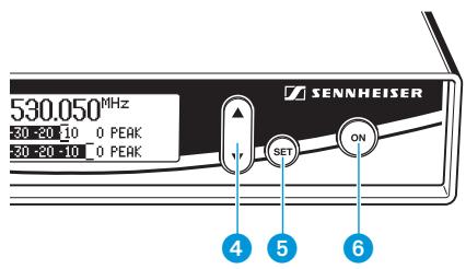
Button backlighting
During standby operation, the ON button ⑥ is backlit in red. When the transmitter is switched on, the SET button ⑤ and the ▲/▼ button ④ are additionally backlit in green.
Indications and displays on the receiver
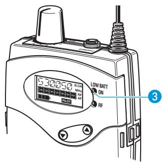
Operation and battery status indication
The red LED (LOW BAT/ON) ③ provides information on the current operating state of the receiver:
Red LED lit up: The receiver is switched on and the capacity of the batteries/accupack BA 2015 is sufficient.
Red LED flashing: The batteries are/the accupack BA 2015 is going flat (LOW BAT)!
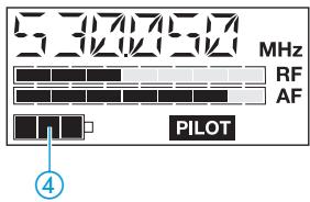
In addition, the 4-step battery status display ④ on the display panel provides information on the remaining battery/accupack BA 2015 capacity:
3 segments: capacity approx. 100 %
2 segments: capacity approx. 70 %
1 segment: capacity approx. 30 %
Battery icon flashing: LOW BAT
Modulation display of the receiving transmitter
The level display for audio signal "AF" shows the modulation of the transmitter.
When the transmitter's audio input level is excessively high (AF peak), the receiver's level display for audio signal "AF" shows full deflection.
"MUTE" display
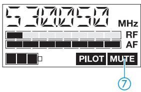
The "MUTE" display ⑦ appears on the display panel when the RF signal of the received transmitter is too weak.
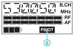
"PILOT" display
The “PILOT” display ⑥ appears on the display panel when the pilot tone evaluation is activated (see “Activating/deactivating the pilot tone evaluation (receiver only)” on page 66).
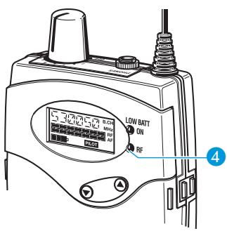
RF signal indication
The green LED (RF) 4 at the front of the receiver lights up when an RF signal is being received.
However, the green LED (RF) does not light up when the audio output is muted because
- the RF signal of the received transmitter is too weak,
- the transmitter is set to mono operation and the receiver's pilot tone evaluation is activated.
Display backlighting
After pressing a button, the display remains backlit for approx. 15 seconds.
Preparing the components for use
SR 300 IEM G2 stereo transmitter
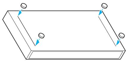
Mounting the transmitter feet
To ensure that the transmitter cannot slip on the surface on which it is placed, four self-adhesive soft rubber feet are supplied.
natural_image
Pure 3D rectangular frame diagram with no text, numbers, or symbols▶ Ensure that the base of the transmitter is clean and free from grease before mounting the rubber feet.
Fix the rubber feet to the base of the transmitter by peeling of the safety paper and fitting them as shown in the digram on the left.
Attention!
Some furniture surfaces have been treated with varnish, polish or synthetics which might cause stains when they come into contact with other synthetics. Despite a thorough testing of the synthetics used by us, we cannot rule out the possibility of staining.
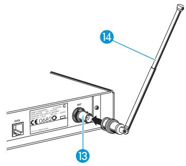
Connecting the antenna
The supplied telescopic antenna can be mounted quickly and easily to the rear of the transmitter and is suitable for all applications where – good transmission conditions provided – a wireless transmission system is to be used without a large amount of installation work.
Connect the telescopic antenna 14 to the BNC socket 13 at the rear of the transmitter.
▶ Pull the end cap to extend the telescopic antenna 14.
Use a remote antenna (available as an accessory) when the transmitter position is not the best antenna position for optimum transmission.
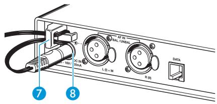
Connecting the mains unit
The transmitter is powered via a mains unit.
▶ Pass the cable through the cable grip 7.
Insert the DC connector on the mains cable into the DC socket 8.
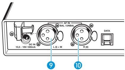
Connecting the amplifier/mixing console
Connect the amplifier/mixing console to the XLR-3F sockets ⑨ (left and MONO) or ⑩ (right).
Both balanced and unbalanced connection is possible (see "Connector assignment" on page 73).
Note:
Any unit that is only suitable for mono operation must be connected to XLR-3F socket 9. In this case, set the transmitter to mono operation via the menu.
| Menu | |
| Tune | 797.075MHz |
| Sensitiv | -24 dB |
| Display | Frequency |
Via the "Sensitiv" menu, adjust the transmitter's input sensitivity (see "Adjusting the sensitivity (transmitter only)" on page 64).

Connecting the headphones/monitoring the audio signal
To monitor the audio signal, connect headphones with a 14 " (6.3 mm) jack plug to the headphone output (PHONES) 1.
Attention! High volume!
Even short exposure to high volume levels will damage your hearing! Set the volume for the connected headphones to the minimum before putting the headphones on.
First, set the volume control ② to the lowest volume by turning it to the left as far as possible. Then gradually turn up the volume.
Volume up? – NO!
When people use headphones, they tend to choose a higher volume than with loudspeakers. Listening at high volume levels for long periods can lead to permanent hearing defects. Please protect your hearing, Sennheiser headphones have an excellent sound quality even at low volumes.
Service interface
The service interface 11 is only required for servicing purposes.
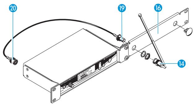
19" rack adapter and antenna mount
For mounting one or two transmitters into a 19" rack, you require the GA 2 rack adapter (available as an accessory). The GA 2 rack adapter consists of:
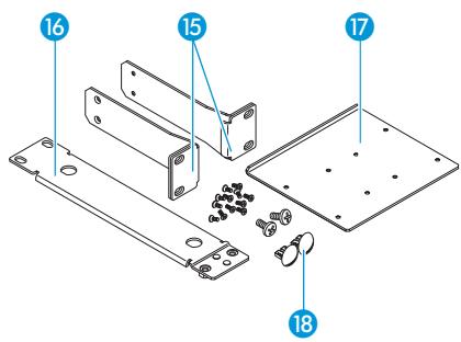
- 2 rack mount "ears" 15
• 1 connecting bar 16
• 1 connecting plate 17
• 2 covering plugs 18 for antenna holes
• 12 recessed head screws M 3x6
• 2 recessed head screws M 6x10

When mounting only one transmitter into a rack, you can use the AM 2 antenna mount (available as an accessory) to mount the transmitter's antenna connection to the front of the GA 2 rack adapter. The AM 2 antenna mount consists of:
- 2 BNC extension cables (screw-in BNC socket 19 to BNC connector 20)
- 2 plains washers
- 2 nuts
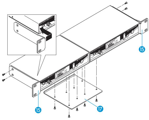
To mount two transmitters into a rack:
Place the two transmitters side by side onto a flat surface, their bottom sides facing upwards.
Align the connecting plate 17 over the holes in the bottom sides of the transmitters.
▶ Secure the connecting plate 17 using eight of the supplied recessed head screws (M 3x6).
Hook the two rack mount "ears" 15 to the front panels of the transmitters.
Secure the rack mount "ears" to the transmitters using two of the supplied recessed head screws (M 3x6) respectively.
Slide the transmitters into the 19" rack.
Secure the rack mount "ears" to the rack.
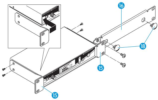
When mounting only one transmitter into a rack, use the connecting bar 16 instead of the second transmitter.
Hook the two rack mount "ears" 15 to the front panels of the transmitter.
Secure the rack mount "ears" to the transmitter using two of the supplied recessed head screws (M 3x6) respectively.
Secure the connecting bar 16 to one of the rack mount "ears" 15 using two of the supplied recessed head screws (M 6x10).
If you are not front mounting the antennas, insert the two covering plugs 18 into the antenna holes of the connecting bar.
Slide the transmitter into the 19" rack.
Secure the rack mount "ears" to the rack.
To mount the transmitter's antenna connection to the front of the GA 2 rack adapter using the AM 2 antenna mount:
Screw the BNC socket 19 of the BNC extension cables to the connecting bar 16 using the supplied plain washer and nut.
Connect the BNC connector 20 to the BNC socket 13 at the rear of the transmitter.
Slide the transmitter into the 19" rack.
Secure the rack mount "ears" to the rack.
Connect the telescopic antenna 14 to the BNC socket 19.
▶ Pull the end cap to extend the telescopic antenna.
EK 300 IEM G2 stereo receiver
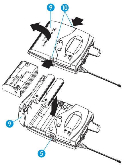
Inserting and replacing the batteries
For powering the EK 300 IEM G2 receiver, two 1.5 V AA size batteries are required.
Press the two unlocking buttons 10 and open the battery compartment cover 9.
Insert the two batteries as shown in the diagram on the left. Please observe correct polarity when inserting the batteries.
▶ Close the battery compartment. The battery compartment cover ⑨ locks into place with an audible click.
Inserting and charging the accupack
The receiver can also be powered via the rechargeable Sennheiser BA 2015 accupack. Insert the accupack into the battery compartment as described above. The transmitter has two charging contacts ⑤ and a sensing contact on its short sides. The accupack can be recharged while remaining in the transmitter. Insert the transmitter into the L 2015 charger (see operating manual of the L 2015 charger).
Note:
For accupack operation of the receiver, only use the BA 2015 accupack in order to ensure optimum operational reliability. For charging the accupack, only use the L 2015 charger. Both the accupack and the charger are available as accessories. The accupack is fitted with an integrated sensor which is – via a third contact – monitored by the electronics of the receiver and the charger. The sensor is necessary for the following control purposes:
- The taking into account of the different voltage characteristics of primary cells (batteries) and accupacks. The battery status indications on the displays, the transmission of transmitter battery status information to the rack-mount receivers and the switch-off thresholds at the end of the operating time are corrected correspondingly. Due to the missing sensor, individual rechargeable battery cells will not be identified as accupacks.
- The monitoring of the accupack temperature during charging in the L 2015 charger.
- The prevention of improper charging of inserted primary cells (batteries). Due to the missing sensor, individual rechargeable battery cells will also not be charged in the L 2015 charger.
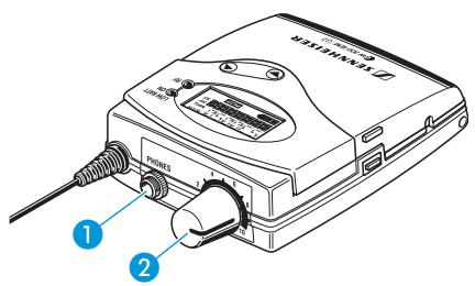
Connecting the headphones
If you use the receiver as part of the monitoring system, connect the supplied in-ear headphones or any Sennheiser stereo headphones with 3.5 mm stereo jack plug to the headphone output (PHONES) 1.
Attention! High volume!
Even short exposure to high volume levels will damage your hearing!
Set the volume for the connected headphones to the minimum before putting the headphones on.
First, set the volume control ② to the lowest volume by turning it to the left as far as possible. Then gradually turn up the volume.
Volume up? – NO!
When people use headphones, they tend to choose a higher volume than with loudspeakers. Listening at high volume levels for long periods can lead to permanent hearing defects. Please protect your hearing, Sennheiser headphones have an excellent sound quality even at low volumes.
Using the components
Switching the components on/off
Switching the transmitter on/off
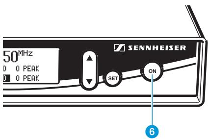
Press the ON button 6 to switch the transmitter on.
To switch the transmitter off, press the ON button until "OFF" appears on the display.
Note:
The transmitter can only be switched off when the standard display is shown on the display panel. Within the operating menu, the ON button serves as the ESC (cancel) key, i.e you cancel your entry and return to the standard display.
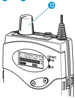
Switching the receiver on/off
To switch the receiver on, turn the volume control 13 clockwise until it clicks. The red LED 3 lights up.
To switch the receiver off, turn the volume control 13 counterclockwise until it clicks. The red LED 3 goes off.
Note:
- The receiver has a short switch-on delay.
- Remove the batteries or the accupack when the receiver will not be used for extended periods of time.
Adjusting the volume
You can adjust the volume at the headphone output on both the transmitter and the receiver.
▶ Use the volume control ② or ⑬ to adjust the volume of the connected headphones.
Volume up? – NO!
When people use headphones, they tend to choose a higher volume than with loudspeakers. Listening at high volume levels for long periods can lead to permanent hearing defects. Please protect your hearing, Sennheiser headphones have an excellent sound quality even at low volumes.
Adjusting the balance
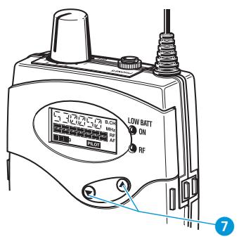
During stereo operation – and provided that the standard display is shown on the display panel – the ▼/▲ rocker button ⑦ serves to adjust the balance between the left and right stereo signal.
During FOCUS operation, the ▼/▲ rocker button ⑦ serves to adjust the relative levels of the two separate channels in the mixed mono signal (see "Stereo/FOCUS selection (receiver only)" on page 64).
Activating/deactivating the lock mode

SR 300 IEM G2
EK 300 IEM G2
Transmitter and receiver have a lock mode that can be activated or deactivated via the operating menu (see “Activating/deactivating the lock mode” on page 67). The lock mode prevents that
- the transmitter is accidentally programmed or switched off during operation
- the balance setting is accidentally changed via the receiver's ▼/▲ rocker button.
Attaching the receiver to clothing
The receiver is attached to clothing (e.g. belt, waistband) with the supplied belt clip.
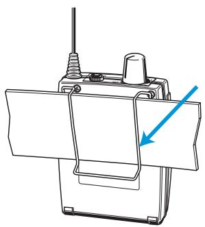
natural_image
Technical line drawing of a mechanical device with a blue arrow pointing to a component (no text or symbols present)The operating menu
To ensure intuitive operation of both transmitter and receiver, the operating menus have been largely standardized. As a result, adjustments to the settings can be made quickly and “without looking” – even in stressful situations, for example on stage or during a live show or presentation.
The buttons
| Buttons | Mode | To ... |
| ON(transmitter only) | Standard display | switch the transmitter on and off |
| Operating menu | cancel the entry and return to the standard display | |
| Setting mode | cancel the entry and return to the standard display | |
| SET | Standard display | get into the operating menu |
| Operating menu | get into the setting mode of the selected menu | |
| Setting mode | store the settings and return to the top menu level | |
| ▲/▼ | Standard display | without function (transmitter) adjust the balance (receiver) |
| Operating menu | change to the previous menu (▲) or change to the next menu (▼) | |
| Setting mode | adjust the setting of the selected menu: option (▲/▼) | |
| ESC(receiver only) | Standard display | without function |
| Operating menu | cancel the entry and return to the standard display | |
| Setting mode | cancel the entry and return to the standard display |
Overview of menus
| Transmitter | Receiver | ||
| Display | Function of the menu | Display | Function of the menu |
| Bank | Switching between channel banks | BANK | Switching between channel banks |
| Channel | Switching between the channels in a channel bank | CHAN | Switching between the channels in a channel bank |
| Tune | Setting a receiving frequency for the channel bank “U” (user bank) | TUNE | Setting a receiving frequency for the channel bank “U” (user bank) |
| — | — | SCAN | Scanning a channel bank for free channels |
| — | — | SQELCH | Adjusting the squelch threshold |
| — | — | ST-FOC | Stereo/FOCUS selection |
| — | — | LTD | Limiting the volume at the headphone output |
| — | — | Hi-BST | Activating/deactivating the frequency boost |
| Sensitiv | Adjusting the sensitivity | — | — |
| Display | Selecting the standard display | DISPLY | Selecting the standard display |
| Name | Entering a name | NAME | Entering a name |
| Reset | Loading the factory-preset default settings | RESET | Loading the factory-preset default settings |
| — | — | PILOT | Activating/deactivating the pilot tone evaluation |
| LCD Contr | Adjusting the contrast of the graphic display | — | — |
| Mode | Stereo/Mono selection | — | — |
| Lock | Activating/deactivating the lock mode | LOCK | Activating/deactivating the lock mode |
| Exit | Exiting the operating menu and returning to the standard display | EXIT | Exiting the operating menu and returning to the standard display |
Working with the operating menu
SR 300 IEM G2
By way of example of the "Tune" menu, this section describes how to use the operating menu.
After switching the unit on, the standard display is shown on the display panel.
EK 300 IEM G2
Getting into the operating menu
| Menu | |
| Channel | 01 |
| Tune | 786.300MHz |
| Scan | |

▶ Press the SET button to get from the standard display into the operating menu.
The last menu selected flashes on the display. With the transmitter, the current setting is additionally displayed.
▶ Press the ▲/▼ buttons to select a menu.
Press the SET button to get into the setting mode of the selected menu. With the receiver, the current setting that can be adjusted flashes on the display. With the transmitter, the name of the menu and the current setting are displayed.
Adjusting a setting
| Tune | |
| U.01 | 786.425 MHz |
| B.CH | |

▶ Press the ▲/▼ buttons to adjust the setting.
By briefly pressing the ▲/▼ buttons, the display jumps either forwards or backwards to the next setting. In the "Channel", "Tune" and "Name" menu, the ▲/▼ buttons feature a "fast search" function. If you hold down a button, the display cycles continuously. The "fast search" function allows you to get fast and easily to your desired setting. With the receiver, the new setting flashes on the display until it is stored.
Storing a setting
Press the SET button to store the setting. "Stored" appears on the display, indicating that the setting has been stored. The display then returns to the top menu level.
With most menus, new settings become effective immediately without having to be stored. An exception are the "Bank", "Channel", "Tune" and "Reset" menus of the transmitter and the "RESET" menu of the receiver. With these menus, new settings only become effective after they have been stored ("Stored" appears on the display, indicating that the setting has been stored).
| Stored |

Exiting the operating menu
▶ Select the “Exit” menu to exit the operating menu and to return to the standard display.
When you have entered the operating menu, the transmitter's ON button serves as the ESC (cancel) key, i.e. by briefly pressing this button, you cancel your entry and return to the standard display. The receiver has a separate ESC button with which you can cancel your entry.
| Menu | |
| Lock | |
| Exit | |
| Bank | 1 |

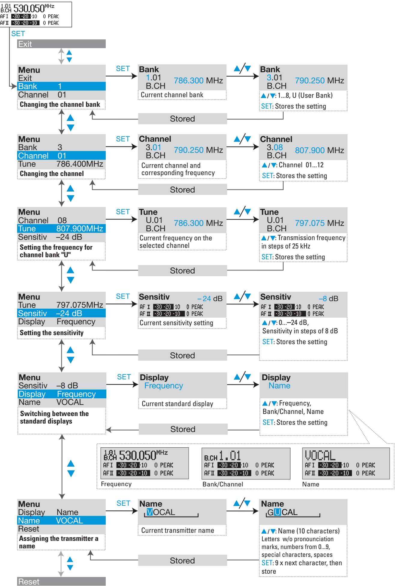
Operating menu of the stereo transmitter
flowchart
graph TD
A["SET"] --> B["Menu Exit"]
B --> C["Menu Bank 1 Channel 01 Changing the channel bank"]
C --> D["Menu Bank 3 Channel 01 Tune 786.400MHz Changing the channel"]
D --> E["Menu Channel 08 Tune 807.900MHz Sensitiv -24 dB Setting the frequency for channel bank "U""]
E --> F["Menu Tune 797.075MHz Sensitiv -24 dB Display Frequency Setting the sensitivity"]
F --> G["Menu Sensitiv -8 dB Display Frequency Name VOCAL Switching between the standard displays"]
G --> H["Menu Display Name Name VOCAL Reset Assigning the transmitter a name"]
H --> I["Reset"]
B --> J["SET"]
J --> K["Bank 1.01 B.CH 786.300 MHz Current channel bank"]
K --> L["Bank 3.01 B.CH 790.250 MHz ▲/▼: 1...8, U (User Bank) SET: Stores the setting"]
D --> M["SET"]
M --> N["Channel 3.01 B.CH 790.250 MHz Current channel and corresponding frequency"]
N --> O["Channel 3.08 B.CH 807.900 MHz ▲/▼: Channel 01...12 SET: Stores the setting"]
E --> P["SET"]
P --> Q["Tune U.01 B.CH 786.300 MHz Current frequency on the selected channel"]
Q --> R["Tune U.01 B.CH 797.075 MHz ▲/▼: Transmission frequency in steps of 25 kHz SET: Stores the setting"]
F --> S["SET"]
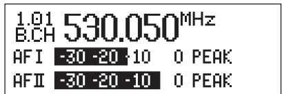
S --> T["Sensitiv -24 dB AF I -30-20-10 AF II -30-20-10"]
T --> U["Sensitiv -8 dB AF I -30-20-10 AF II -30-20-10"]
U --> V["Sensitiv -8 dB AF I -30-20-10 AF II -30-20-10"]
V --> W["Sensitiv -8 dB AF I -30-20-10 AF II -30-20-10"]
W --> X["Sensitiv -8 dB AF I -30-20-10 AF II -30-20-10"]
X --> Y["Sensitiv -8 dB AF I -30-20-10 AF II -30-20-10"]
Y --> Z["Sensitiv -8 dB AF I -30-20-10 AF II -30-20-10"]
Z --> AA["Sensitiv -8 dB AF I -30-20-10 AF II -30-20-10"]
AA --> AB["Sensitiv -8 dB AF I -30-20-10 AF II -30-20-10"]
AB --> AC["Sensitiv -8 dB AF I -30-20-10 AF II -30-20-10"]
AC --> AD["Sensitiv -8 dB AF I -30-20-10 AF II -30-20-10"]
AD --> AE["Sensitiv -8 dB AF I -30-20-10 AF II -30-20-10"]
AE --> AF["Sensitiv -8 dB AF I -30-20-10 AF II -30-20-10"]
AF --> AG["Sensitiv -8 dB AF I -30-20-10 AF II -30-20-10"]
AG --> AH["Sensitiv -8 dB AF I -30-20-10 AF II -30-20-10"]
AH --> AI["Sensitiv -8 dB AF I -30-20-10 AF II -30-20-10"]
AI --> AJ["Sensitiv -8 dB AF I -30-20-10 AF II -30-20-10"]
AJ --> AK["Sensitiv -8 dB AF I -30-20-10 AF II -30-20-10"]
AK --> AL["Sensitiv -8 dB AF I -30-20-10 AF II -30-20-10"]
AL --> AM["Sensitiv -8 dB AF I -30-20-10 AF II -30-20-10"]
AM --> AN["Sensitiv -8 dB AF I -30-20-10 AF II -30-20-10"]
AN --> AO["Sensitiv -8 dB AF I -30-20-10 AF II -30-20-10"]
AO --> AP["Sensitiv -8 dB AF I -30-20-10 AF II -30-20-10"]
AP --> AQ["Sensitiv -8 dB AF I -30-20-10 AF II -30-20-10"]
AQ --> AR["Sensitiv -8 dB AF I -30-20-10 AF II -30-20-10"]
AR --> AS["Sensitiv -8 dB AF I -30-20-10 AF II -30-20-10"]
AS --> AT["Sensitiv -8 dB AF I -30-20-10 AF II -30-20-10"]
AT --> AU["Sensitiv -8 dB AF I -30-20-10 AF II -30-20-10"]
AU --> AV["Sensitiv -8 dB AF I -30-20-10 AF II -30-20-10"]
AV --> AW["Sensitiv -8 dB AF I -30-20-1O PEAK"]
AW --> AX["Sensitiv -8 dB AF I -30-2O PEAK"]
AX --> AY["Sensitiv -8 dB AF I -3O PEAK"]
AY --> AZ["Sensitiv -8 dB AF I -3O PEAK"]
AZ --> BA["Sensitiv -8 dB AF I -3O PEAK"]
BA --> BB["Sensitiv -8 dB AF I -3O PEAK"]
BB --> BC["Sensitiv -8 dB AF I -3O PEAK"]
BC --> BD["Sensitiv -8 dB AF I -3O PEAK"]
AD --> BE["Set"]
BE --> BF["Store"]
subgraph Settings
direction TB
direction LR
style A fill:#f9f,stroke:#333
style B fill:#ccf,stroke:#333
style C fill:#cfc,stroke:#333
style D fill:#fcc,stroke:#333
style E fill:#ffc,stroke:#333
style F fill:#cff,stroke:#333
style G fill:#ffc,stroke:#333
style H fill:#cfc,stroke:#333
style I fill:#fcc,stroke:#333
style J fill:#cfc,stroke:#333
style K fill:#cfc,stroke:#333
style L fill:#cfc,stroke:#333
style M fill:#cfc,stroke:#333
style N fill:#cfc,stroke:#333
style O fill:#cfc,stroke:#333
style P fill:#cfc,stroke:#333
style Q fill:#cfc,stroke:#333
style R fill:#cfc,stroke:#333
style S fill:#cfc,stroke:#333
style T fill:#cfc,stroke:#333
style U fill:#cfc,stroke:#333
style V fill:#cfc,stroke:#333
style W fill:#cfc,stroke:#333
style X fill:#cfc,stroke:#333
style Y fill:#cfc,stroke:#333
style Z fill:#cfc,stroke:#333
style AA fill:#cfc,stroke:#333
style AB fill:#cfc,stroke:#333
style AC fill:#cfc,stroke:#333
style AD fill:#cfc,stroke:#333
style AE fill:#cfc,stroke:#333
style AF fill:#cfc,stroke:#333
style AG fill:#cfc,stroke:#333
style AH fill:#cfc,stroke:#333
style AI fill:#cfc,stroke:#333
style AJ fill:#cfc,stroke:#333
style AK fill:#cfc,stroke:#333
style AL fill:#cfc,stroke:#333
style AM fill:#cfc,stroke:#333
style AN fill:#cfc,stroke:#333
style AO fill:#cfc,stroke:#333
style AP fill:#cfc,stroke:#333
style AQ fill:#cfc,stroke:#333
style AR fill:#cfc,stroke:#333
style AS fill:#cfc,stroke:#333
style AT fill:#cfc,stroke:#333
style AU fill:#cfc,stroke:#333
style AV fill:#cfc,stroke:#333
style AW fill:#cfc,stroke:#333
style AX fill:#cfc,stroke:#333
style AY fill:#fcc,stroke:#f66
style AZ fill:#fcc,stroke:#f66
style BA fill:#fcc,stroke:#f66
style BB fill:#fcc,stroke:#f66
style BC fill:#fcc,stroke:#f66
style CC fill:#fcc,stroke:#f66
style CD fill:#fcc,stroke:#f66
style DJ fill:#fcc,stroke:#f66
style DE fill:#fcc,stroke:#f66
style FD fill:#fcc,stroke:#f66
style EJ fill:#fcc,stroke:#f66
style EF fill:#fcc,stroke:#f66
style EG fill:#fcc,stroke:#f66
style EH fill:#fcc,stroke:#f66
style EI fill:#fcc,stroke:#f66
style AJ fill:#fcc,stroke:#f66
style AKI fill:#fcc,stroke:#f66
style ALI fill:#fcc,stroke:#f66
style AMI fill:#fcc,stroke:#f66
style ANI fill:#fcc,stroke:#f66
style AOI fill:#fcc,stroke:#f66
style APJ fill:#fcc,stroke:#f66
style AQJ fill:#fcc,stroke:#f66
style ARJ fill:#fcc,stroke:#f66
style ASJ fill:#fcc,stroke:#f66
style ATJ fill:#fcc,stroke:#f66
style AUJ fill:#fcc,stroke:#f66
style AVJ fill:#fcc,stroke:#f66
style AWJ fill:#fcc,stroke:#f66
style AXJ fill:#fcc,stroke:#f66
style AYJ fill:#fcc,stroke:#f66
style AZJ fill:#fcc,stroke:#f66
style BAJ fill:#fcc,stroke:#f66
style BBJ fill:#fcc,stroke:#f66
style ACJ fill:#fcc,stroke:#f66
style ADJ fill:#fcc,stroke:#f66
style AEJ fill:#fcc,stroke:#f66
style AFJ fill:#fcc,stroke:#f66
style AGJ fill:#fcc,stroke:#f66
style AHJ fill:#fcc,stroke:#f66
style AIJ fill:#fcc,stroke:#f66
style AJJ fill:#fcc,stroke:#f66
style AKJ fill:#fcc,stroke:#f66
style ALJ fill:#fcc,stroke:#f66
style ANJ fill:#fcc,stroke:#f66
style AOJ fill:#fcc,stroke:#f66
style APJL fill:#fcc,stroke:#f66
style AQJL fill:#fcc,stroke:#f66
style ARJL | SET |
SE
%% Settings and labels are not explicitly provided in the code.
flowchart
graph TD
A["Menu Name: GUITAR"] --> B["Reset"]
B --> C["Reset Reset? No"]
C --> D["Reset Reset? Yes"]
D --> E[""reset" = Yes"<br> E --> F["reset" = No:<br> SET: Reset is cancelled"]
B --> G["LCD Contr: IIIIII...."]
G --> H["Loading the factory-preset default settings"]
H --> I["Menu Reset"]
I --> J["LCD Contr: IIIIII...."]
J --> K["Mode Stereo"]
K --> L["Adjusting the contrast of the graphic display"]
L --> M["Stored"]
M --> N["Menu LCD Contr: IIIIII...."]
N --> O["Mode Stereo"]
O --> P["Lock Off"]
P --> Q["Switching between stereo and mono operation"]
Q --> R["Menu Mode Mono"]
R --> S["Lock Off"]
S --> T["Lock mode activated or deactivated"]
T --> U["Lock On"]
U --> V["Lock mode = On:<br> SET: Stores the setting, returns to standard display"]
V --> W["Menu Lock On"]
W --> X["Exit Bank 3"]
X --> Y["Exiting the operating menu"]
Y --> Z["Bank 3"]
style A fill:#f9f,stroke:#333
style Z fill:#f9f,stroke:#333
subgraph Settings
direction TB
A1["SET"] --> A2["Reset"]
A2 --> A3["Reset Reset? No"]
A3 --> A4["Security check"]
A4 --> A5["▲/▼"]
A5 --> A6[""reset" = Yes"<br> A6 --> A7["reset" = No:<br> SET: Reset is cancelled"]
A7 --> A8[""reset" = Yes"<br> A8 --> A9["reset" = No:<br> SET: Reset is cancelled"]
A9 --> A10[""reset" = Yes"<br> A10 --> A11["reset" = No:<br> SET: Reset is cancelled"]
A11 --> A12[""reset" = Yes"<br> A12 --> A13["reset" = No:<br> SET: Reset is cancelled"]
A13 --> A14[""reset" = Yes"<br> A14 --> A15["reset" = No:<br> SET: Reset is cancelled"]
A15 --> A16[""reset" = Yes"<br> A16 --> A17["reset" = No:<br> SET: Reset is cancelled"]
A17 --> A18[""reset" = Yes"<br> A18 --> A19["reset" = No:<br> SET: Reset is cancelled"]
A19 --> A20[""reset" = Yes"<br> A20 --> A21["reset" = No:<br> SET: Reset is cancelled"]
A21 --> A22[""reset" = Yes"<br> A22 --> A23["reset" = No:<br> SET: Reset is cancelled"]
A23 --> A24[""reset" = Yes"<br> A24 --> A25["reset" = No:<br> SET: Reset is cancelled"]
A25 --> A26[""reset" = Yes"<br> A26 --> A27["reset" = No:<br> SET: Reset is cancelled"]
A27 --> A28[""reset" = Yes"<br> A28 --> A29["reset" = No:<br> SET: Reset is cancelled"]
A29 --> A30[""reset" = Yes"<br> A30 --> A31["reset" = No:<br> SET: Reset is cancelled"]
A31 --> A32[""reset" = Yes"<br> A32 --> A33["reset" = No:<br> SET: Reset is cancelled"]
A33 --> A34[""reset" = Yes"<br> A34 --> A35["reset" = No:<br> SET: Reset is cancelled"]
A35 --> A36[""reset" = Yes"<br> A36 --> A37["reset" = No:<br> SET: Reset is cancelled"]
A37 --> A38[""reset" = Yes"<br> A38 --> A39["reset" = No:<br> SET: Reset is cancelled"]
A39 --> A40[""reset" = Yes"<br> A40 --> A41["reset" = No:<br> SET: Reset is cancelled"]
A41 --> A42[""reset" = Yes"<br> A42 --> A43["reset" = No:<br> SET: Reset is cancelled"]
A43 --> A44[""reset" = Yes"<br> A44 --> A45["reset" = No:<br> SET: Reset is cancelled"]
A45 --> A46[""reset" = Yes"<br> A46 --> A47["reset" = No:<br> SET: Reset is cancelled"]
A47 --> A48[""reset" = Yes"<br> A48 --> A49["reset" = No:<br> SET: Reset is cancelled"]
A49 --> A50[""reset" = Yes"<br> A50 --> A51["reset" = No:<br> SET: Reset is cancelled"]
A51 --> A52[""reset" = Yes"<br> A52 --> A53["reset" = No:<br> SET: Reset is cancelled"]
A53 --> A54[""reset" = Yes"<br> A54 --> A55["reset" = No:<br> SET: Reset is cancelled"]
end
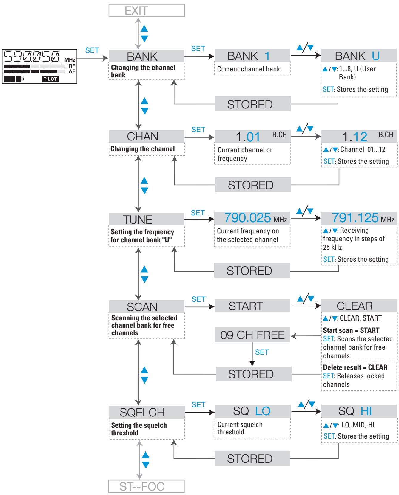
Operating menu of the stereo receiver
flowchart
graph TD
    A["EXIT"] --> B["BANK"]
    B --> C["BANK 1"]
    C --> D["BANK U"]
    D --> E["STATED"]
    B --> F["CHAN"]
    F --> G["TUNE"]
    G --> H["SCAN"]
    H --> I["SQELCH"]
    I --> J["ST--FOC"]
    B --> K["STATED"]
    K --> L["STATED"]
    L --> M["09 CH FREE"]
    M --> N["START"]
    N --> O["CLEAR"]
    O --> P["SET: SCans the selected channel bank for free channels"]
    P --> Q["SET: Releases locked channels"]
    Q --> R["SQ LO"]
    R --> S["SET: LO, MID, HI"]
    S --> T["STATED"]
    T --> U["STATED"]
    U --> V["Setting the squelch threshold"]
    V --> W["SCanning the selected channel bank for free channels"]
    W --> X["SET: Scans the selected channel bank for free channels"]
    X --> Y["Delete result = CLEAR"]
    Y --> Z["SET: Releases locked channels"]
    Z --> AA["SET: Releases locked channels"]
    AA --> AB["Setting the squelch threshold"]
    AB --> AC["ST--FOC"]
flowchart
graph TD
    A["SQLCH"] --> B["ST--FOC"]
    B -->|SET| C["STEREO"]
    C -->|✓/▼| D["FOCUS"]
    D -->|▲/▼: Stereo, Focus<br>SET: Stores the setting| E["STORED"]
    E --> F["LTD"]
    F -->|SET| G["LTD.OFF"]
    G -->|✓/▼| H["LTD.ON"]
    H -->|▲/▼: OFF, ON<br>SET: Stores the setting| I["STORED"]
    I --> J["HI--BST"]
    J -->|SET| K["HB.OFF"]
    K -->|✓/▼| L["HB.ON"]
    L -->|▲/▼: OFF, ON<br>SET: Stores the setting| M["STORED"]
    M --> N["DISPLY"]
    N -->|SET| O["CHAN"]
    O -->|✓/▼| P["NAME"]
    P -->|▲/▼: FREQ, NAME, CHAN<br>SET: Stores the setting| Q["STORED"]
    Q --> R["NAME"]
    R -->|SET| S["VOCAL"]
    S -->|✓/▼| T["GUCAL"]
    T -->|▲/▼: Enter a name (6 characters) Letters w/o pronunciation marks, numbers from 0..9, special characters, spaces<br>SET: 5 x next character, then store| U["STORED"]
    U --> V["RESET"]
    V --> W["Assigning the receiver a name"]
    W --> X["DISPLY"]
    X --> Y["CAN"]
    Y --> Z["NAME"]
    Z --> AA["STORED"]
    AA --> AB["RESET"]
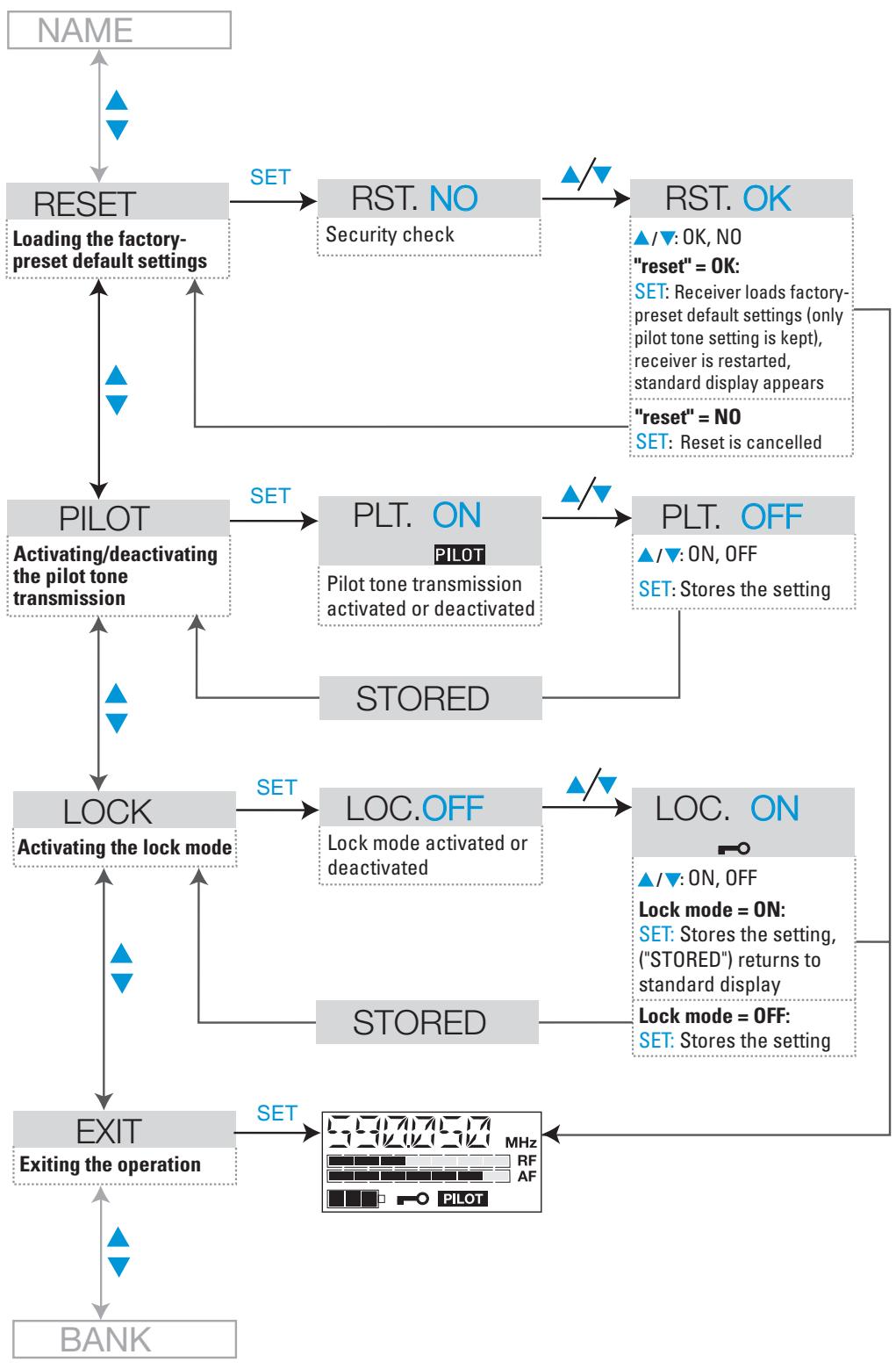
flowchart
graph TD
    A["NAME"] --> B["RESET"]
    B --> C["LOADING THE FACTORY-Preset DEFAULT SETTINGS"]
    C --> D["PILOT"]
    D --> E["PLT. ON"]
    E --> F["PLT. OFF"]
    F --> G["LOC. ON"]
    G --> H["EXIT"]
    H --> I["BANK"]

    B --> J["SET"]
    J --> K["RST. NO"]
    K --> L["RST. OK"]
    L --> M["▲/▼: OK, NO\n"reset" = OK:\nSET: Receiver loads FACTORY-Preset DEFAULT SETTINGS (only pilot tone setting is kept), receiver is restarted, standard display appears\n"reset" = NO\nSET: Reset is cancelled"]

    D --> N["SET"]
    N --> O["PLT. ON"]
    O --> P["PLT. OFF"]
    P --> Q["STORED"]

    D --> R["SET"]
    R --> S["LOCK"]
    S --> T["LOC.OFF"]
    T --> U["LOC. ON"]

    G --> V["SET"]
    V --> W["LOCK MODE = ON:\nSET: Stores the setting, ("STORED") returns to standard display\nLock MODE = OFF:\nSET: Stores the setting"]

    H --> X["SET"]
    X --> Y["EXIT\nExiting the operation"]

    I --> Z["BANK"]

    style A fill:#f9f,stroke:#333
    style B fill:#ccf,stroke:#333
    style C fill:#cfc,stroke:#333
    style D fill:#fcc,stroke:#333
    style E fill:#cff,stroke:#333
    style F fill:#ffc,stroke:#333
    style G fill:#fcf,stroke:#333
    style H fill:#cff,stroke:#333
    style I fill:#ffc,stroke:#333
    style J fill:#cfc,stroke:#333
    style K fill:#cfc,stroke:#333
    style L fill:#cfc,stroke:#333
    style M fill:#cfc,stroke:#333
    style N fill:#cfc,stroke:#333
    style O fill:#cfc,stroke:#333
    style P fill:#cfc,stroke:#333
    style Q fill:#cfc,stroke:#333
    style R fill:#cfc,stroke:#333
    style S fill:#cfc,stroke:#333
    style T fill:#cfc,stroke:#333
    style U fill:#cfc,stroke:#333
    style V fill:#cfc,stroke:#333
    style W fill:#cfc,stroke:#333
    style X fill:#cfc,stroke:#333
    style Y fill:#cfc,stroke:#333
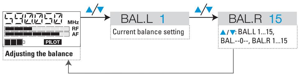
flowchart
graph TD
    A["PILOT"] --> B["BAL.L 1"]
    B --> C["BAL.R 15"]
    D["Adjusting the balance"] --> A
    style A fill:#f9f,stroke:#333
    style B fill:#ccf,stroke:#333
    style C fill:#cfc,stroke:#333
    note1["▲/▼: BAL.L 1...15, BAL.--0--, BAL.R 1...15"] --> B
Adjustment tips for the operating menu
Switching between channel banks
BANK Bank
Via the "Bank" menu, you can switch between the nine channel banks of the ew 300 IEM G2 transmitter and receiver. The channel banks "1" to "8" have up to 12 switchable channels that are factory-preset to a transmission/receiving frequency (see "The channel bank system" on page 42). The channel bank "U" (user bank) also has up to 12 switchable channels to store your selection out of 1440 transmission/receiving frequencies that are freely selectable within the preset frequency range.
When switching from one channel bank to another, the channel with the lowest channel number is automatically displayed. If, during the last scan of this channel bank, an interfering frequency was detected on the channel with the lowest channel number, the receiver display panel automatically displays the next free channel (see below).
Switching between the channels in a channel bank
CHAN Channel
Via the "Channel" menu, you can switch between the channels in a channel bank.
Always set the transmitter and the receiver of a transmission link to the same channel. After scanning a channel bank (see “Scanning the channel banks for free channels (receiver only)” on page 62), only the free channels are displayed. Set the transmitter to one of the free channels
Selecting the frequencies to be stored in the channel bank "U"
TUNE Tune
Via the “Tune” menu, you can select the frequencies to be stored in the channel bank “U” (user bank).
L21
When you have selected one of the channel banks "1" to "8" and then select the "Tune" menu, the transmitter or receiver automatically switches to channel 01 of the channel bank "U". In this case, "U.01" briefly appears on the display.
▶ Use the ▲/▼ buttons to select the desired transmission or receiving frequency. Transmission and receiving frequencies are tunable in 25-kHz steps within a switching bandwidth of 36 MHz max. For intermodulation-free frequencies, please refer to the enclosed frequency table.
Scanning the channel banks for free channels (receiver only)
SCAN
Before putting one or several transmission links into operation, you should scan the selected channel bank for free channels.
Starting the scan and storing the scan result
Before starting the scan, switch all transmitters of your system off, since channels used by switched-on transmitters will not be displayed as “free channels”.
▶ Select the "SCAN" menu.
Select "START" and confirm your selection by pressing the SET button. After the scan is completed, the number of free channels is displayed. Pressing the SET button once more will store the scan result and lock all channels that are used or subject to interference.
Releasing locked channels
▶ Select the "SCAN" menu.
▶ Select "CLEAR" and confirm your selection by pressing the SET button. All channels in this channel bank can now be selected again.
Multi-channel operation
For multi-channel operation, only use the free channels in a channel bank.
Before putting the transmission links into operation, we recommend performing an auto scan.
▶ Select a channel bank on a receiver.
▶ Scan this channel bank for free channels. If not enough free channels are available in the selected channel bank, repeat the scan with another channel bank.
Apply the scan result to all other transmitters and receivers.
Adjusting the squelch threshold (receiver only)
The receiver is equipped with a squelch that can be adjusted via the "SQELCH" menu. The squelch eliminates annoying noise when the transmitter is switched off. It also suppresses sudden noise when there is no longer sufficient transmitter power received by the receiver.
Note:
Before adjusting the squelch threshold to a different setting, use the volume control 13 to set the volume for the connected headphones to the minimum.
There are three possible squelch settings:
- LO = low
- MID = middle
- HI = high
Selecting the setting "LO" reduces the squelch threshold, selecting the setting "HI" increases the squelch threshold. Adjust the squelch threshold – with the transmitter switched off – to the lowest possible setting that suppresses hissing noise.

IMPORTANT! Notes:
- If the squelch threshold is adjusted too high, the transmission range will be reduced. Therefore, always adjust the squelch threshold to the lowest possible setting.
- When in the setting mode of the "SQELCH" menu, pressing the ▼ button for more than three seconds will switch the squelch off. "SQ.OFF" appears on the display. If no RF signal is being received, his-sing noise will occur. This setting is for test purposes only.
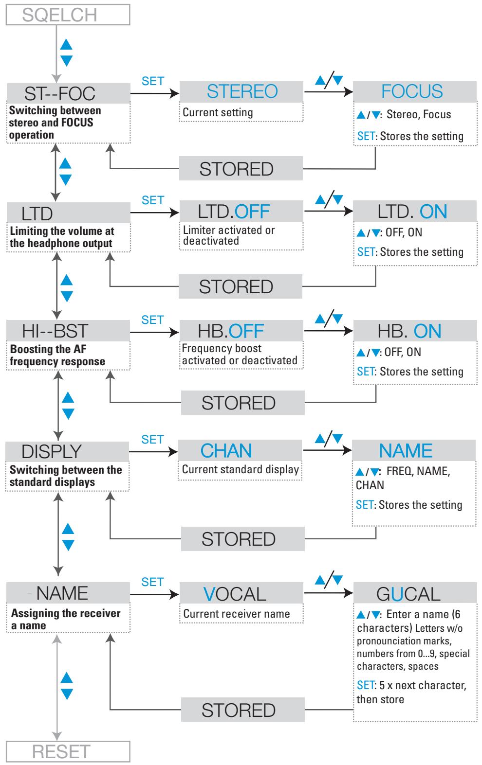
Stereo/FOCUS selection (receiver only)
ST-FOC
Via the "ST-FOC" menu, you can switch between stereo and FOCUS operation.
In both operating modes, the SR 300 IEM G2 stereo transmitter has to be set to stereo operation.
When the receiver is set to stereo operation, the left-right signals are available as usual.
When the receiver is set to FOCUS operation, the left-right signals are mixed and are available as a mono signal in both headphone channels. Use the ▼/▲ rocker button to adjust the relative levels of the two separate channels in the mixed mono signal (see “Adjusting the balance” on page 53).
Limiting the volume at the headphone output (receiver only)
LTD
Via the "LTD" menu, you can switch the limiter on and off. With the limiter switched on, the volume at the headphone output will be reduced.
Activating/deactivating the frequency boost (receiver only)
HI-BST
Via the "HI-BST" menu, you can boost the AF frequency response at 10 kHz. As a result, headphones with magnetic transducers sound better.
Adjusting the sensitivity (transmitter only)
Sensitiv
To match the transmitter to the output level of the connected unit (e.g. mixing console), you can adjust the input sensitivity in four steps of 8 dB via the "Sensitiv" menu.
The input sensitivity is adjusted too high when close talking distances, speakers with loud voices or loud music passages cause overmodulation in the transmission link. In this case, the transmitter's "PEAK" warning will light up and the receiver's level display for audio signal "AF" will show full deflection.
If, on the other hand, the sensitivity is adjusted too low, the transmission link will be undermodulated, which would result in a signal with high background noise.
The sensitivity is correctly adjusted when the level display for audio signal "AF" shows full deflection only during the loudest passages.
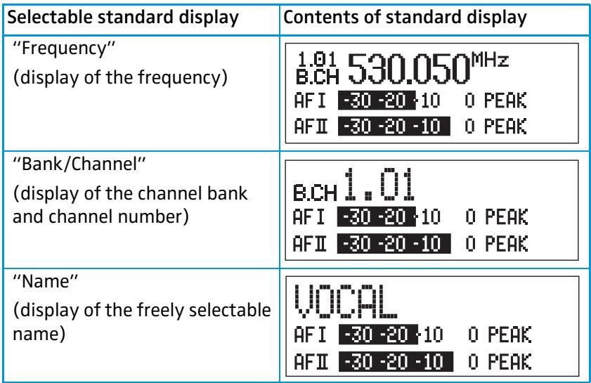
Selecting the standard display
DISPLY Display
Via the "Display" menu, you can select the standard display.
SR 300 IEM G2 stereo transmitter
 |
EK 300 IEM stereo receiver
| Selectable standard display | Contents of standard display |
| “FREQ” | 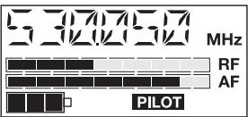 |
| “NAME” | 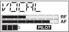 |
| “CHAN” | 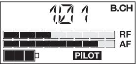 |
Entering a name
NAME Name
Via the "Name" menu, you can enter a freely selectable name for the transmitter and the receiver. You can, for example, enter the name of the performer for whom the adjustments have been made.
The name can be displayed on the standard display and can consist of up to ten characters (transmitter) and up to six characters (receiver) such as:
- letters (without pronunciation marks),
- numbers from 0 to 9,
- special characters e.g. () - . _ and spaces.
To enter a name, proceed as follows:
Press the SET button to get into the setting mode of the "Name" menu. The first segment starts flashing on the display.
With the ▲/▼ buttons you can now select a character. By briefly pressing
a button, the display jumps either forwards or backwards to the next character. If you hold down a button, the display starts cycling continuously.
▶ Press the SET button to change to the next segment and select the next character.
Have you entered the name completely? Press the SET button to store your setting and to return to the previous menu level.
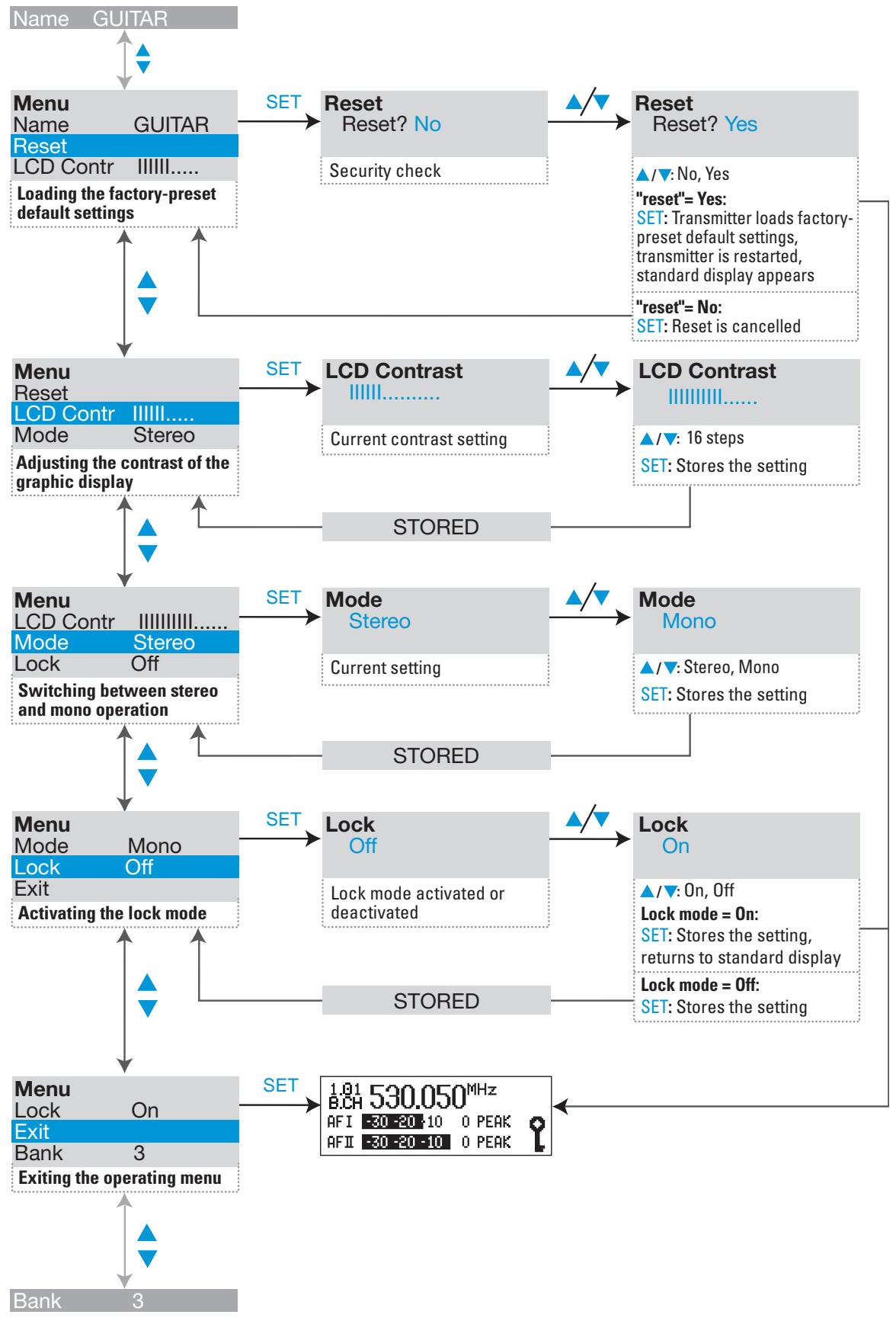
Loading the factory-preset default settings
RESET Reset
Via the "Reset" menu, you can load the factory-preset default settings. With the receiver, however, the selected setting for the pilot tone remains unchanged. After the reset, the unit is restarted and the standard display is shown on the display panel.
Activating/deactivating the pilot tone evaluation (receiver only)
PILOT Pilot
Via the "Pilot" menu, you can activate or deactivate the pilot tone evaluation of the receiver. The pilot tone is used
• to code the transmitter's stereo signal,
• to support the squelch function (Squelch).
During stereo operation, the transmitter adds the pilot tone to the transmitted stereo signal and the receiver detects and evaluates the pilot tone. When the transmitter is set to mono operation, deactivate the pilot tone evaluation on the receiver.
You can combine units of first and second generation ew 300 IEM systems without any problems.
Adjusting the contrast of the graphic display (transmitter only)
LCD-Contr
Via the "LCD Contr" menu, you can adjust the contrast of the graphic display in 16 steps.
Stereo/Mono selection (transmitter only)
Mode
Via the "Mode" menu, you can switch the transmitter between mono and stereo operation.
Note:
Connect any unit that only delivers a mono signal to the transmitter's left XLR-3F socket ⑨ and set the transmitter to mono operation. The receiver automatically "identifies" the transmitted audio signal and does not need to be set to mono operation. However, you have to deactivate the pilot tone evaluation on the receiver.
Activating/deactivating the lock mode
LOCK Lock
Via the "Lock" menu, you can activate or deactivate the lock mode.

The lock mode icon on the display indicates that the lock mode is activated.
To deactivate the lock mode, first press the SET button. Then press the ▲/▼ buttons to select "Lock Off". If you confirm your selection by pressing the SET button, the buttons can be operated as usual.
SR 300 IEM G2
EK 300 IEM G2
Exiting the operating menu
EXIT Exit
Via the "Exit" menu, you can exit the operating menu and return to the standard display.
Troubleshooting
Error checklist
| Problem | Possible cause | Possible solution |
| No operation indication | Batteries are flat or accupack is flat (receiver only) | Replace the batteries or recharge the accupack |
| No mains connection (transmitter only) | Check the connections of the mains unit | |
| No RF signal | Transmitter and receiver are not on the same channel | Set transmitter and receiver to the same channel |
| Transmitter is out of range | Check the squelch threshold setting (see “Adjusting the squelch threshold (receiver only)” on page 63) or reduce the distance between transmitter and receiving antenna | |
| RF signal available, no audio signal, “MUTE” display appears on the display panel | Transmitter is set to mono operation and the pilot tone evaluation of the receiver is activated | Deactivate the pilot tone evaluation on the receiver |
| Receiver’s squelch threshold is adjusted too high | See “Adjusting the squelch threshold (receiver only)” on page 63) | |
| Audio signal has a high level of background noise | Transmitter sensitivity is adjusted too low | See “Adjusting the sensitivity (transmitter only)” on page 64 |
| Audio signal is distorted | Transmitter sensitivity is adjusted too high | See “Adjusting the sensitivity (transmitter only)” on page 64 |
| No access to a certain channel | During scanning, an RF signal has been detected on this channel and the channel has been locked | See “Scanning the channel banks for free channels (receiver only)” on page 62 |
If problems occur that are not listed in the above table or if the problems cannot be solved with the proposed solutions, please contact your local Sennheiser agent for assistance.
Recommendations and tips
... for the EK 300 IEM G2 receiver
- The antenna of the EK 300 IEM G2 should hang freely and be at least 1 cm away from the body. The antenna must not be in direct contact with the skin.
... for optimum reception
- Transmission range depends to a large extent on location and can vary from about 10 m to about 150 m. There should be a “free line of sight” between transmitting and receiving antennas.
- If, with the SR 300 IEM G2 transmitter, transmission conditions are unfavourable, you should use a remote antenna which is connected via antenna cable.
- To avoid overmodulating the receiver, observe a minimum distance of 5 m between transmitting and receiving antennas.
- Observe a minimum distance of 50 cm between transmitting antennas and metal objects (such as cross members or reinforced-concrete walls).
... for multi-channel operation
- For multi-channel operation, you can only use the channels in a channel bank. Each of the channel banks "1" to "8" accommodates up to 12 factory-preset frequencies which are intermodulation-free. For alternative frequency combinations, please refer to the enclosed frequency table. The freely selectable frequencies can be selected via the "Tune" menu and can be stored in the channel bank "U".
- When using several transmitters simultaneously, interference can be avoided by maintaining a minimum distance of 20 cm between two transmitters. For multi-channel applications, use the AC 2 transmitter combiner (see “Accessories” on page 73).
Care and maintenance
Use a slightly damp cloth to clean the units from time to time.
Note:
Do not use any cleansing agents or solvents.
Additional information
HDX noise reduction
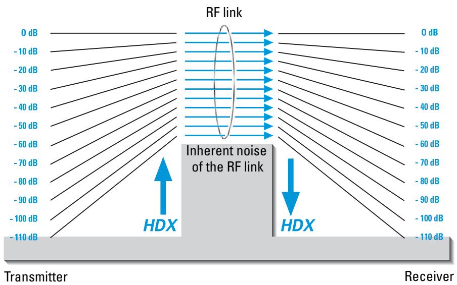
The evolution wireless G2 series is equipped with HDX, the Sennheiser noise reduction system that reduces RF interference. It increases the signal-to-noise ratio in wireless audio transmission to more than 110 dB.
HDX is a wideband commander system which compresses the audio signal in the transmitter in a 2:1 ratio (related to dB) to lift it above the inherent noise floor of the RF link. In the receiver the signal is expanded in an identical and opposite way in a 1:2 ratio to restore the original signal, at the same time reducing the RF noise to below the noise floor of the receiver.
HDX has been specially developed for high quality radiomicrophone systems.
Note:
Only transmitters and receivers that are equipped with HDX can work correctly with each other. If non HDX equipment was mixed with HDX, the dynamic range would be drastically reduced and the transmission would sound blunt and flat. HDX is permanently active and cannot be switched off.
Wireless transmission systems
With the ew 300 IEM G2 system, Sennheiser puts an end to cable tangles and enables complete freedom of movement. The systems operate exclusively in the UHF band. UHF transmission is extremely reliable and is far less prone to interference than the overcrowded VHF band – harmonics from mains units, fluorescent tubes, refrigerators, computers, etc. are virtually eliminated. Also indoor propagation of UHF radio waves is better than VHF so that the RF power can be kept low – this is also an advantage when using multi-channel systems. Finally, UHF frequency ranges are being approved all over the world for radiomicrophone usage – in some countries licence-free.
Correct adjustment of transmitter sensitivity is vital. Too high and you get overmodulation and distortion, too low and you get undermodulation and a noisy signal. Please set the sensitivity correctly for the microphone/usage and check it before every performance to ensure best operation.
Squelch
Pilot tone squelch
When the transmitter is set to stereo operation, it adds a 19-kHz pilot tone to the audio signal. The receiver checks incoming audio signals to see if the pilot tone is present. In the absence of the 19-kHz signal, the receiver's audio output will remain muted, even if a strong RF signal is present.
This prevents strong interfering signals from causing hissing noise in the receiver when the transmitter is switched off.
Field strength-dependent squelch
Depending on the strength of the received RF signal, the receiver's audio output is opened or muted. Via the "SQELCH" menu of the receiver, the squelch threshold can be adjusted in three steps (LO, MID, HI).
Specifications
System
| RF characteristics | |
| Modulation | wideband FM stereo, MPX pilot tone |
| Frequency ranges | 518–554, 626–662, 740–776, 786–822, 830–866 MHz |
| Transmission/receiving frequencies | 8 channel banks with up to 12 factory-preset channels each1 channel bank with up to 12 freely selectable channels(1440 frequencies, tunable in steps of 25 kHz) |
| Switching bandwidth | 36 MHz |
| Nominal/peak deviation | ±24 kHz/±48 kHz |
| Frequency stability | ≤ ±15 ppm |
| AF characteristics | |
| Noise reduction system | Sennheiser HDX |
| AF frequency response | 40–15,000 Hz |
| MPX pilot tone (Frequenz/Hub) | 19 KHz/±4 kHz |
| S/N ratio (at 1 mV and peak deviation) | ≥ 91 dB(A) |
| THD (at nominal deviation and 1 kHz) | ≤ 0.9 % |
| General data | |
| Temperature range | -10 °C to +55 °C |
| Dimensions of carrying case [mm] | 380 x 370 x 70 |
| Weight of carrying case | approx. 3000 g |
| IE 3 in-ear headphones | |
| Frequency response | 40–20,000 Hz |
| Max. SPL | 118 dB SPL |
| Impedance | 32 Ω |
| EK 300 IEM G2 stereo receiver | |
| RF characteristics | |
| Receiver principle | non diversity |
| Sensitivity (with HDX, peak deviation) | < 2.5 μV at 52 dBA _rms S/N ratio |
| Adjacent channel rejection | ≥ 70 dB |
| Intermodulation attenuation | ≥ 70 dB |
| Blocking | ≥ 80 dB |
| Squelch | 4 steps: OFFLO: 5 dBμVMID: 15 dBμVHI: 25 dBμV |
| Pilot tone squelch (MPX pilot tone) | can be switched off |
| AF characteristics | |
| Headphone output | 3.5 mm jack socket |
| AF output voltage (at peak deviation 1 kHz _AF ) PHONES | 2 x ≥ 100 mW at 32 Ω |
| Overall device | |
| Power supply | 2 AA size batteries, 1.5 V |
| Nominal voltage | 2.4 V |
| Max. power consumption at nominal voltage | approx. 190 mA (2 x 30 mW) |
| Power consumption with switched-off receiver | ≤ 250 μA |
| Operating time (with batteries) | 6–10 h (depending on volume level) |
| Operating time (with BA 2015 accupack) | 6–10 h (depending on volume level) |
| Dimensions [mm] | 82 x 64 x 24 |
| Weight (incl. batteries) | approx. 170 g |
SR 300 IEM G2 stereo transmitter
RF characteristics
RF output power at 50 Ω
Antenna output
≥ 20 mW, internally adjustable to 10 mW
BNC socket, 50 Ω
AF characteristics
Headphone output
Output power at headphone output
AF input
Max. input voltage (at peak deviation, 1 kHz)
Input impedance
1/4'' (6.3 mm) stereo jack socket
≥ 100 mW at 32 Ω (2x)
2 x XLR-3 socket, balanced
+10dB _u
10 kΩ
Overall device
Power supply
Nominal voltage
Max. power consumption at nominal voltage
Dimensions [mm]
Weight
10.5-16 V DC
12 V DC
approx. 300 mA
212 × 145 × 38
approx. 1100 g
Connector assignment
SR 300 IEM G2:
1/4'' (6.3 mm) stereo jack plug for headphone output
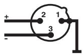
SR 300 IEM G2:
XLR-3M connector
SR 300 IEM G2:
DC connector for power supply
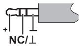
EK 300 IEM G2:
3.5 mm stereo jack plug for headphone output


Accessories
GA 2 19" rack adapter
AM 2 Antenna mount for mounting antennas to the front of the GA 2
A 1031-U UHF antenna,
passive, omni-directional, can be mounted onto a stand
A 2003-UHF UHF antenna,
passive, directional, can be mounted onto a stand
GZL 1019-A1 Antenna cable with BNC connectors 1 m
GZL 1019-A5 Antenna cable with BNC connectors 5 m
AC 2 Transmitter combiner,
for combining the RF signals of up to four transmitters onto a single antenna and for powering up to four transmitters
NT 3 Plug-in mains unit for AC 2
IE 3 In-ear headphones
IES 3 1 pair of ear-moulds
BA 2015 Accupack
L 2015 Charger for BA 2015 accupack
CC 2 Carrying case for ew 300 IEM G2 system
DEUTSCH
The guarantee period for this Sennheiser product is 24 months from the date of purchase. Excluded are accessory items, rechargeable or disposable batteries that are delivered with the product; due to their characteristics these products have a shorter service life that is principally dependent on the individual frequency of use.
The guarantee period starts from the date of original purchase. For this reason, we recommend that the sales receipt be retained as proof of purchase. Without this proof (which is checked by the responsible Sennheiser service partner) you will not be reimbursed for any repairs that are carried out.
Depending on our choice, guarantee service comprises, free of charge, the removal of material and manufacturing defects through repair or replacement of either individual parts or the entire device. Inappropriate usage (e.g. operating faults, mechanical damages, incorrect operating voltage), wear and tear, force majeure and defects which were known at the time of purchase are excluded from guarantee claims. The guarantee is void if the product is manipulated by non-authorised persons or repair stations.
In the case of a claim under the terms of this guarantee, send the device, including acces-sories and sales receipt, to the responsible service partner. To minimise the risk of transport damage, we recommend that the original packaging is used. Your legal rights against the seller, resulting from the contract of sale, are not affected by this guarantee.
The guarantee can be claimed in all countries outside the U.S. provided that no national law limits our terms of guarantee.
FRANÇAIS
conform to the basic requirements of EEC Directive 89/336/EEC resp. R&TTE Directive 1999/5/EC.
To effect correct application of the requirements stated in the EEC Directives, the following standards were consulted:
Before putting the device into operation, please observe the respective country-specific regulations!
Important:
30900 Wedemark, Germany
Phone +49 (5130) 600 0
Fax +49 (5130) 600 300
www.sennheiser.com