E12 - Uncategorized AVer - Free user manual and instructions
Find the device manual for free E12 AVer in PDF.


| Brand | AVer |
| Model | E12 |
| Product type | Cart / mobile stand for audio-video equipment |
| Material | Steel with black finish |
| Maximum load per shelf | 38.1 kg (84 lb) |
| Number of shelves | 3 (estimate) |
| Dimensions (W x D x H) | Approximately 120 x 60 x 100 cm (estimate) |
| Weight | Approximately 25 kg (estimate) |
| Power supply | Integrated grounded mains socket |
| Input voltage | 100-240 V AC, 50/60 Hz |
| Power cable | 2 meters, grounded plug |
| Main functions | Mobile stand for monitors, TVs, document cameras; adjustable shelves; locking casters |
| Care and cleaning | Clean with a soft dry cloth. Do not use abrasive products |
| Safety | Requires wall attachment to prevent tipping. Do not overload. Unplug before moving |
| Spare parts and repairability | Contact AVer customer service |
| General information | Designed for professional use in meeting rooms or classrooms |
Frequently Asked Questions - E12 AVer
User questions about E12 AVer
0 question about this device. Answer the ones you know or ask your own.
Ask a new question about this device
Download the instructions for your Uncategorized in PDF format for free! Find your manual E12 - AVer and take your electronic device back in hand. On this page are published all the documents necessary for the use of your device. E12 by AVer.
USER MANUAL E12 AVer
natural_image
Line drawing of an internal electronic device with multiple ports and a labeled power outlet (no text or symbols on the device itself)E12
User Manual

WARNING
AVERTISSEMENT
ALWAYS FOLLOW SAFETY PRECAUTIONS
RESPECTEZ TOUJOURS LES CONSIGNES DE SÉCURITÉ
This cabinet is intended for use only with loading as indicated. Use with loads greater than indicated may result in instability causing possible injury.
MISE EN GARDE
CAUTION
■ DO NOT allow anyone to sit, stand or climb on the station.
■ DO NOT lift the station.
■ DO NOT block the ventilation holes used for air circulation.
■ DO NOT overload objects on the station shelves. (shelf maximum loading = 38.1kg / 84lbs).
■ DO NOT put any devices that exceed the maximum loading weight on the shelf of station.
■ DO NOT put any devices (e.g. TV, Monitor, Documents camera, etc.) on top of the station.
■ DO NOT use any TV/monitor/display on top of the station.
■ Before moving the station, disconnect the power from the wall outlet.
■ When moving the station, make sure the power cord is firmly plugged into the socket and confirm main earth connection.
■ When disconnecting the AC power cord, be absolutely sure to first disconnect the plug from the outlet socket.
The socket-outlet shall be installed near the equipment and shall be easily accessible.
ATTENTION!
Federal Communications Commission Statement
NOTE: This equipment has been tested and found to comply with the limits for a Class A digital device, pursuant to part 15 of the FCC Rules. These limits are designed to provide reasonable protection against harmful interference when the equipment is operated in a commercial environment. This equipment generates, uses, and can radiate radiofrequency energy and, if not installed and used in accordance with the instruction manual, may cause harmful interference to radio communications. Operation of this equipment in a residential area is likely to cause harmful interference in which case the user will be required to correct the interference at his own expense.
FCC Caution: Any changes or modifications not expressly approved by the party responsible for compliance could void the user's authority to operate this equipment.
This device complies with part 15 of the FCC Rules.
Operation is subject to the following two conditions:
(1) This device may not cause harmful interference, and
(2) this device must accept any interference received, including interference that may cause undesired operation.
DISCLAIMER
No warranty or representation, either expressed or implied, is made with respect to the contents of this documentation, its quality, performance, merchantability, or fitness for a particular purpose. Information presented in this documentation has been carefully checked for reliability; however, no responsibility is assumed for inaccuracies. The information contained in this documentation is subject to change without notice.
In no event will AVer Information Inc. be liable for direct, indirect, special, incidental, or consequential damages arising out of the use or inability to use this product or documentation, even if advised of the possibility of such damages.
TRADEMARKS
“AVer” is a trademark owned by AVer Information Inc. Other trademarks used herein for description purpose only belong to each of their companies.
COPYRIGHT
©2021 AVer Information Inc. All rights reserved.
All rights of this object belong to AVer Information Inc. Reproduced or transmitted in any form or by any means without the prior written permission of AVer Information Inc. is prohibited. All information or specifications are subject to change without prior notice.
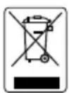
The mark of Crossed-out wheeled bin indicates that this product must not be disposed of with your other household waste. Instead, you need to dispose of the waste equipment by handing it over to a designated collection point for the recycling of waste electrical and electronic equipment. For more information about where to drop off your waste equipment for recycling, please contact your household waste disposal service or the shop where you purchased the product.
Before running the system, make sure the power cord is firmly plugged into the socket and confirm main earth connection.
CAUTION
When disconnecting the AC power cord, be absolutely sure to first disconnect the plug from the outlet socket.
Contact Information
AVer Information Inc., Americas
https://www.averusa.com
668 Mission Ct., Fremont, CA 94539, USA
Tel: +1 (408) 263 3828
Toll-free: +1 (877) 528 7824
Technical support: support.usa@aver.com
CONTENTS
Contact Information....5
Package Contents.... 1
Tools Required 2
Dimensions.... 3
Diagram.... 3
Front and Back 3
Sides 4
Top and Bottom....4
Installation 5
Step 1: Install door lock cover (Optional)....6
Step 2: Connect the power strip to a wall outlet .... 7
Step 3: Adapter configuration .... 8
Step 4: Extend and fix the sides of the chassis....9
Step 5: Insert dividers into the slots on the shelf.... 10
Step 6: Cable management....11
Step 7: Install top cover (Optional) 12
Step 8: Secure the charging station (Optional).... 12
Desk mount (Optional) 13
Troubleshooting....14
Specifications....15
Service and Warranty 16
Appendix – Earthing....17
Package Contents
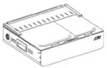
The following items are included in the package. Please check if each item is available before installing.
natural_image
Line drawing of a rectangular electronic device with internal components and ventilation slots (no text or symbols)(folded)
natural_image
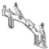
Technical line drawing of a mechanical assembly with no visible text or symbolsDivider x 13
natural_image
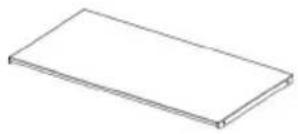
Simple line drawing of a rectangular block (no text or symbols)Top cover x 1
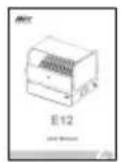
User Manual
natural_image
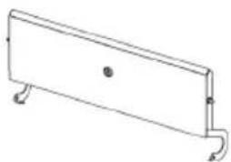
Simple line drawing of a rectangular object with two curved legs and a central hole (no text or symbols)Door lock cover x 1
natural_image
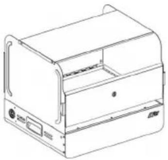
Line drawing of a laboratory device with a lid and control panel (no text or symbols)(Unfolded) E12 Station
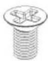
Flat head screw x 11 (M4x5L)
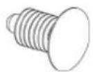
Snap rivet x 8

Umbrella head screw x 4 (M4 x 5L)
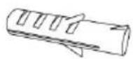
Concrete anchor x 6
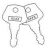
Lock key x 2
natural_image
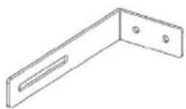
Technical line drawing of a L-shaped metal bracket with two holes (no text or symbols)L- Shaped mounting bracket x 2
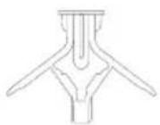
Drywall anchor x 6
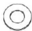
Washer x 6
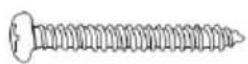
Anchor screw x 6
Tools Required
See the assembly instructions for the tools you'll need to use
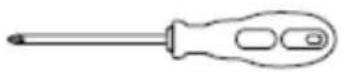
Screwdriver (For station use)
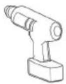
Drill
(For desk mount use)
Dimensions
Diagram
Front and Back
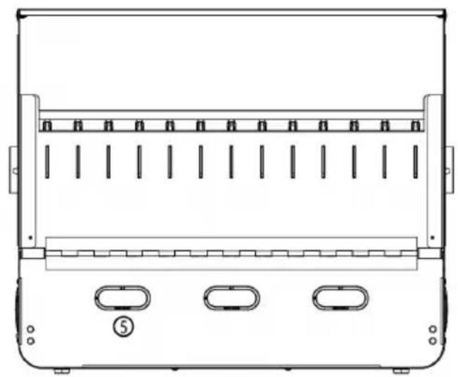
natural_image
Technical line drawing of a mechanical device with multiple slots and mounting holes (no text or symbols)Sides
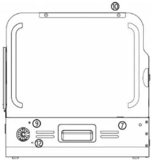
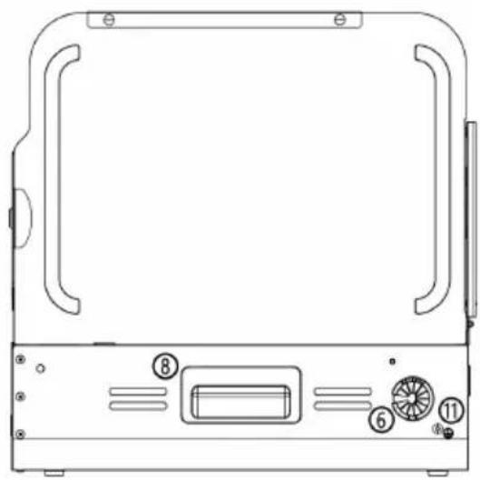
natural_image
Technical line drawing of a device casing with labeled components (no text or symbols beyond numbers)Top and Bottom
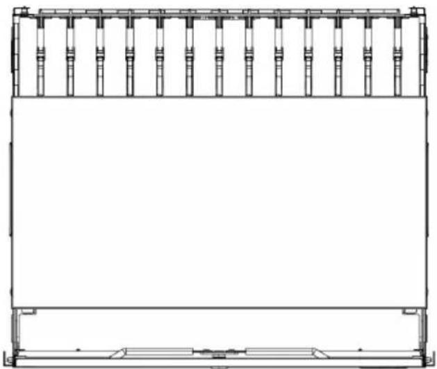
natural_image
Technical line drawing of a rectangular electronic device with vertical connectors and mounting brackets (no text or symbols)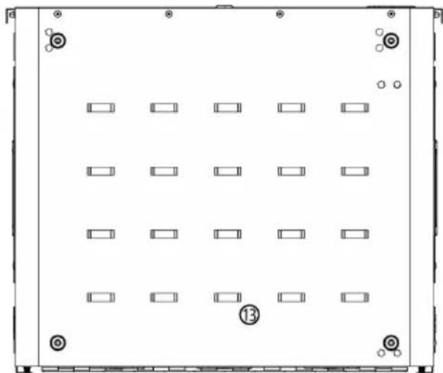
natural_image
Front view of a rectangular electronic device with 13 slots and mounting holes (no text or symbols)Front and Back Sides Top and Bottom
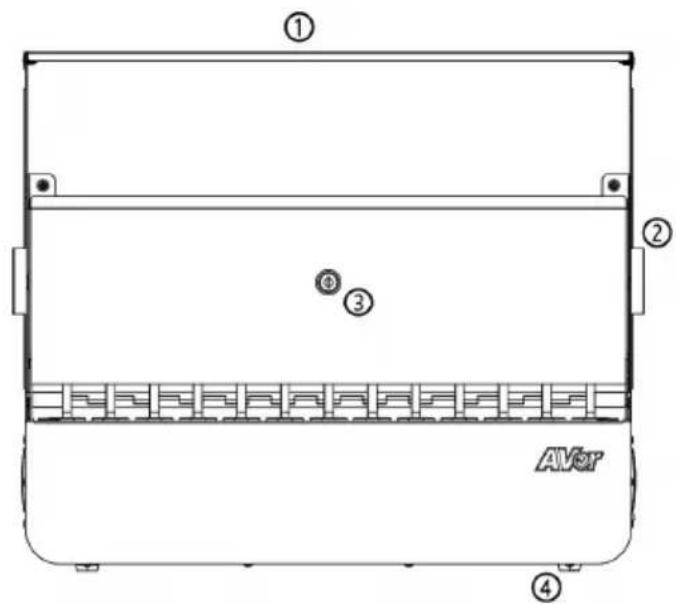
- Top cover
- Power cable hole 13. Ventilation holes
- Finger pull
- Ventilation holes
- Door lock
- Handle
- Foot rubber 9. Fix Plate holes
- Adapter cable holes 10. Snap Rivet holes
11.
Ground
12.
Antitheft
Installation
Please check that you have taken out all package contents out and the numbers of each item is correct before getting started.
Parts list
A Charging station
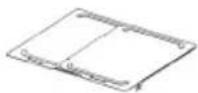
Chassis
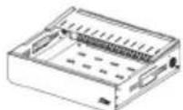
Adapter drawer
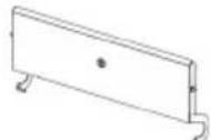
Door lock cover
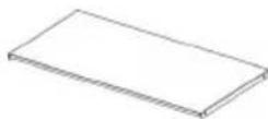
Top cover
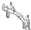
Divider x 13

Snap rivet x 8

Flat head screw x 11

Umbrella head screw x 4
B Desk mount (optional)
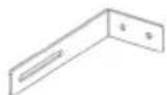
L- Shaped bracket x 2
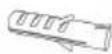
Concrete anchor x 6
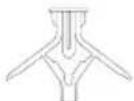
Drywall anchor x 6
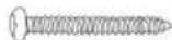
Anchor screw x 6

Washer x 6
Before installing the charging station
- Be sure to reserve enough space for installation. It is recommended to reserve at least 47.2"(W)* 35.42"(D) inches.
- It is recommended to allocate 2 people for efficient assembly.
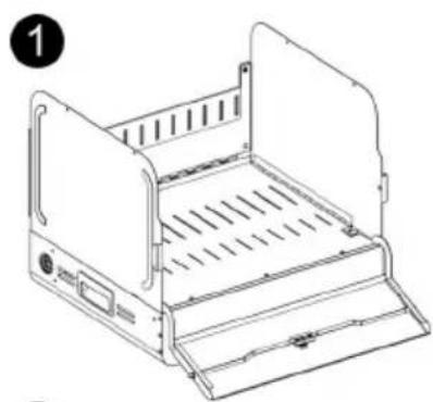
Step 1: Install door lock cover (Optional)
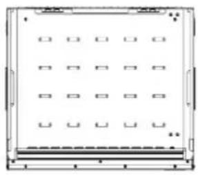
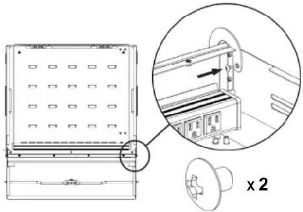
First, attach the door lock cover hole on the nut column, and then install the door lock cover using 2 x umbrella head screws into the adapter drawer.
1
natural_image
Pure diagram of a rectangular frame with 16 small square cutouts, no text or symbols present.2
natural_image
Technical line drawing of a mechanical device with an inset close-up showing internal components (no text or symbols)[Note]
It is recommended to use a long screwdriver to tighten screws.
Step 2: Connect the power strip to a wall outlet
- Remove the packing material of the power strip.
- Feed the power strip through the hole provided.
- Connect the power strip to a wall outlet.
1 2
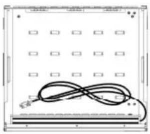
natural_image
Front view of a rectangular electronic device with a coiled cable and grid of square components (no visible text or symbols)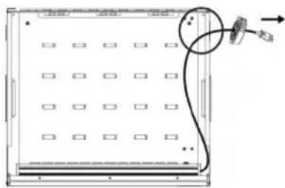
natural_image
Diagram of a device panel with grid layout and cable connection (no text or symbols)3
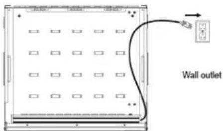
[Note]
Set the power socket to the OFF position before plugging the charging station to wall outlet.
Step 3: Adapter configuration
- Place the power adapter onto the adapter drawer in order.
- Pass the DC-end of the adapter cable through the hole located on the back of the adapter drawer.
- Plug-in the AC-end of the adapter cable to the power AC socket.
- Watch your hand when you place the chassis on the adapter drawer. Please make sure the chassis is placed along the edge of the door lock. (The chassis faces outwards, the door lock face inwards)
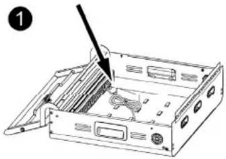
natural_image
Diagram of a computer drive bay with an arrow pointing to a cable slot (no text or symbols present)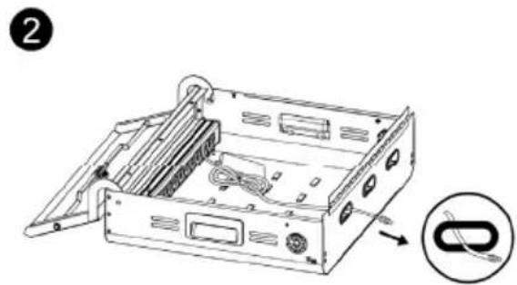
natural_image
Diagram of an open computer case with internal components and a magnified view showing cable (no text or symbols)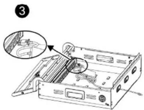
[Note]
- Please place the power adapter onto the adapter drawer in order, don't stack the adapters.
- For some device adapters that are not compatible with the power strip (EX: e.g. iPad 8, iPad Air 4th generation), please contact AVer for help.
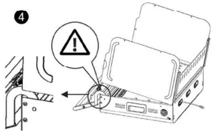
Step 4: Extend and fix the sides of the chassis
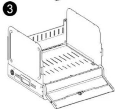
- Extend the sides of the chassis out at right angles.
- Insert 2 x flat head screws and 2 x snap rivets through the hole located on the corners of the rear plate. Each corner has one on the top and one on the bottom (4 screws / snap rivets total).
- Fix the chassis on the adapter drawer with 3 x flat head screws.
natural_image
Line drawing of a portable electronic device with ventilation slots and control panel (no text or symbols)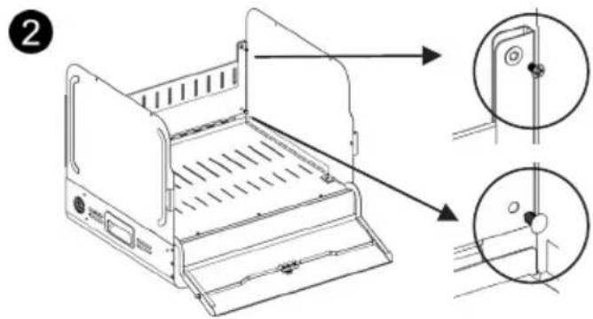
natural_image
Line drawing of a portable electronic device with ventilation slots and control panel (no text or symbols)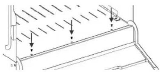
natural_image
Technical line drawing of a mechanical component with diagonal hatching and downward arrows indicating force or movement (no text or symbols)[Note]
• It is recommended to use a long screwdriver to tighten screws.
- It is recommended to allocate 2 people for efficient assembly.
Step 5: Insert dividers into the slots on the shelf
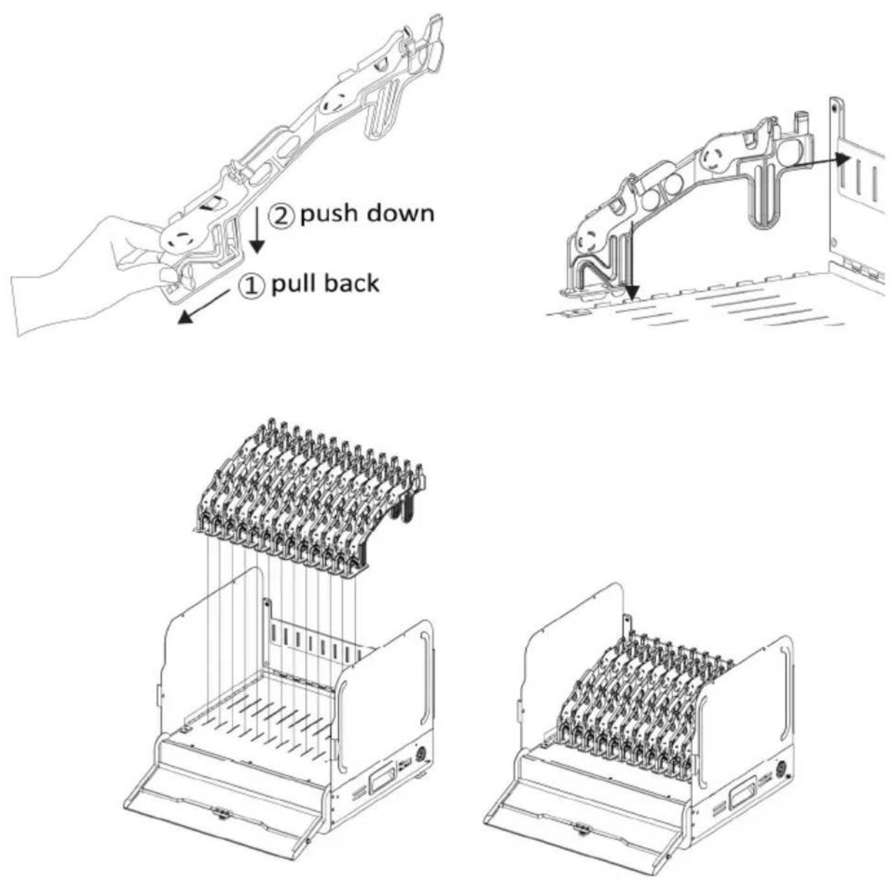
Insert 13 x dividers into the slots on the shelf. Ensure that all dividers are properly seated.
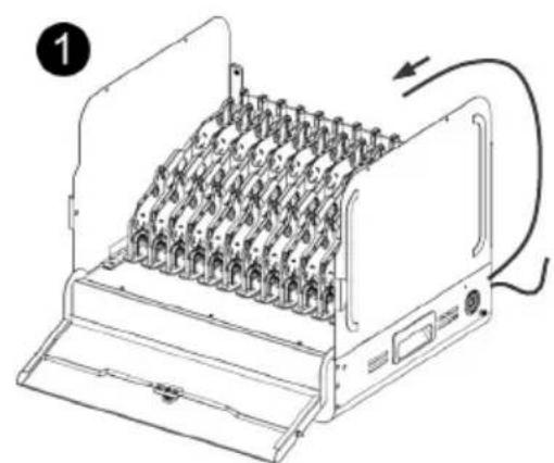
Step 6: Cable management
- Determine the length of power cable that is needed to reach from the hole located on the back of adapter drawer to the devices.
- Route the adapter DC-end cable. Along with the V-shape routing groove.
- Snap the locking piece until hear a "click" to firmly secure the DC-end cable. Remember to reserve enough length of power cable to connect the power plug of the device.
- Place the mobile device into the bay and plug in the DC-connector to the mobile device.
natural_image
Line drawing of a printer with multiple spools and a paper holder, showing internal structure and wiring (no text or symbols)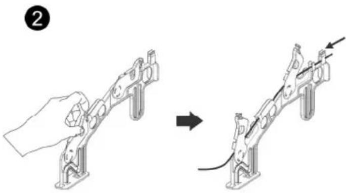
natural_image
Diagram showing a hand holding a mechanical component before and after assembly, with no visible text or symbols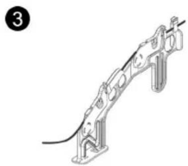
natural_image
Technical line drawing of a mechanical assembly with no visible text or symbols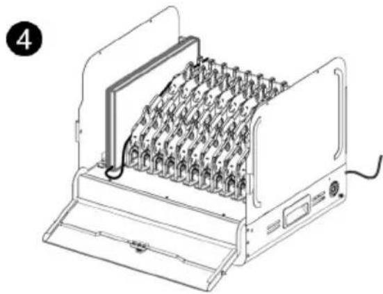
natural_image
Line drawing of an electronic device with multiple ports and wiring, no text or symbols present[Note]
It is recommended to allocate 2 people for efficient device cabling.
Step 7: Install top cover (Optional)
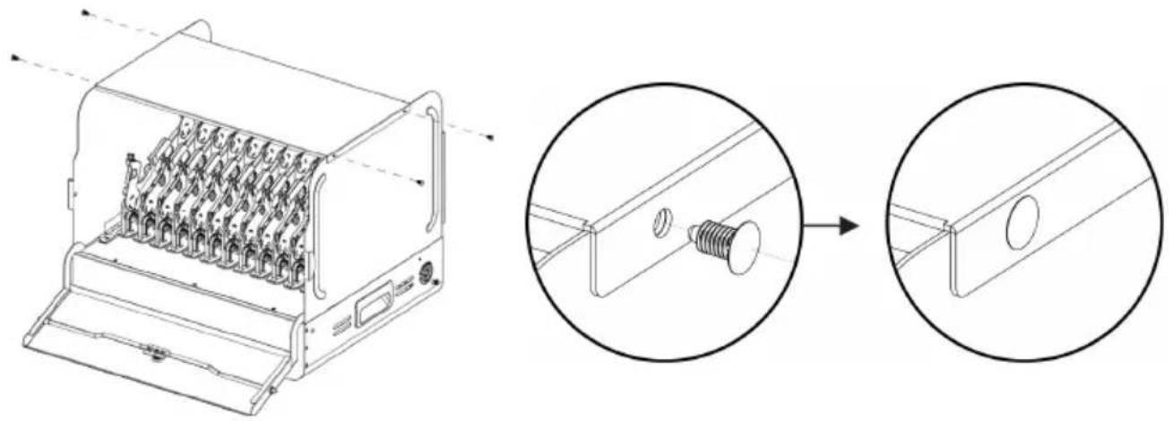
Place the top cover on the top of both sides. Use 4 x snap rivets on the two outer holes on both sides to prevent removal.
natural_image
Technical line drawing of a device with internal components and a magnified inset showing a screw inserted into a bracket (no text or symbols)[Note]
If you insert the snap rivet into the wrong hole, it is recommended to remove it with a scissor and then reinstall with a new snap rivet.
Step 8: Secure the charging station (Optional)
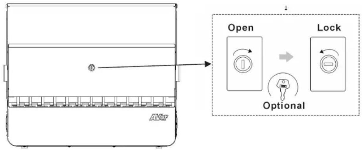
For security, use the lock key to secure the door.
Desk mount (Optional)
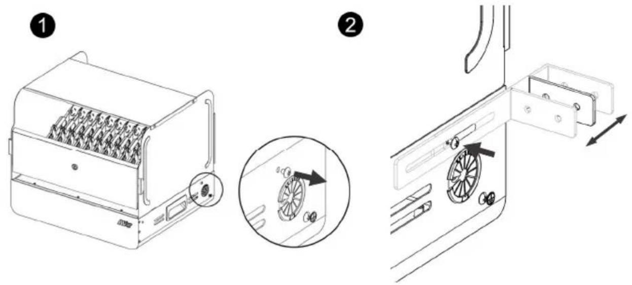
- Remove the pre-installed screws on the top of cable grommet on each side (See the figure as below for exact locations).
- Determine the appropriate L- shaped mounting bracket location and fix 2 x L- shaped mounting bracket with screws.
- Secure the station to the wall studs for drywall mounting. Drill the holes at the wall studs through the drywall, and firmly tap 4 x drywall anchors in until they are flush with the wall.
- For concrete wall mounting, please use 4 x concrete anchors and fully flush the anchors to the drilled holes.
- Secure the charging station to the wall with 4 x anchor screws (with 4 x washers).
[Note]
- Please note that the charging station needs to be placed on the desk. The unit may be secured to the surface by inserting 2 screws appropriately.
- The station must be installed by a qualified technician. Use suitable mounting means when installing to cinder block, concrete or drywall.
• It is recommended to use a screwdriver to loosen the screws.
Troubleshooting
Q: Why are all of my devices plugged in but not charging?
A: 1. Make sure power cords are undamaged.
-
Make sure power cords are firmly inserted into the available socket with stable current.
-
Make sure the power plug and current consumption are compliant with your country specification standards.
Q: My station's main power cord or station components are damaged. Are they covered under warranty?
A: We provide a 10 year warranty on the station and main frame, and 5 years warranty on the electrical components.
Q: How do I know if my devices will exceed more than the allotted current?
A: Have a qualified electrician verify the current consumption of your devices. Perform the test with devices installed and batteries discharged.
Q: When I plug in the device it trips the circuit breaker. What is wrong?
A: You may have other equipment or appliances sharing the same circuit that is causing a circuit overload. Have a qualified electrician check that adequate power is available in the circuit.
Specifications
| Model | E12 |
| Capacity | 12 |
| Supported Devices | Mobile devices up to 15.6" |
| Charging Type | Fully Charging |
| Power Specification | Power Strip: 100-120V ~ 50/60Hz, 12A |
| Security | Door Lock cover: 2 points mechanism with key lock function. |
| Fixed Shelf | Yes |
| Shelf Support Weight(ea.) | 38.1 kg (84lbs) |
| Adapter Shelves(ea.) | 6.35 kg (14lbs) |
| Working Temperature | 0°~30°C |
| Working RH% | 10%~90% |
| Storage Temperature | -40°C~60°C |
| Storage RH% | 5%~95% |
| Warranty | 10 years station and tray5 years electrical components |
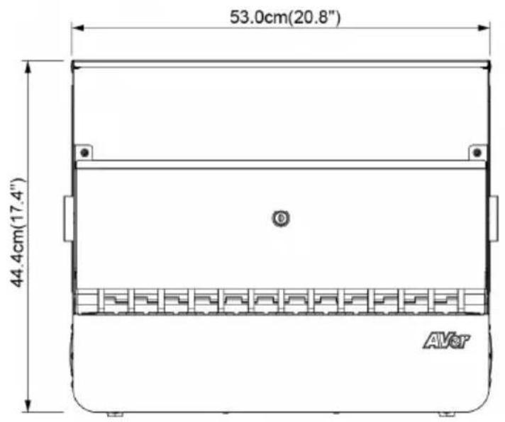
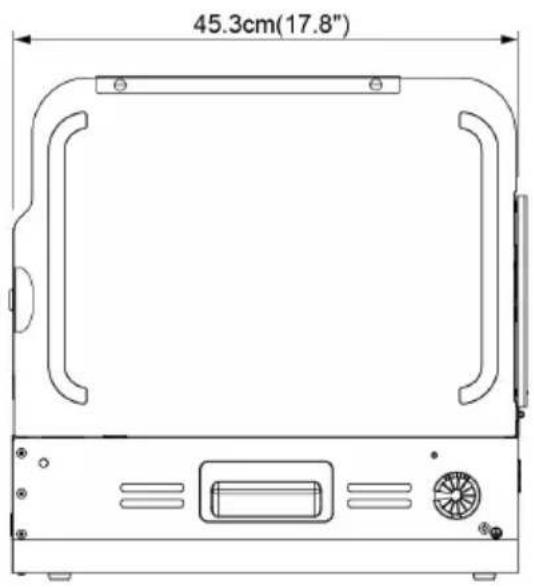
| Station Dimensions(W x D x H) | Unfolded527(W) ×453.4 (D) × 444.7 (H)mm20.75"(W)×17.85"(D)×17.5" (H)Folded527(W) ×453.4 (D) × 123 (H)mm20.75"(W)×17.85"(D)×4.84" (H) |
| Slot Dimensions(W x D x H) | 30 (W)×425.8(D)×311.3(H) mm1.18"(W)×17.76"(D)×12.26"(H) |
| Weight without Devices | 20 kg (44.09 lbs) ± 3 kg(6.61 lbs) |
[Note]
- Supported Devices: please check actual device size, including power cable for compatibility with device compartment size. If in doubt please contact AVer for confirmation.
- Specifications are subject to change without prior notice.
Service and Warranty
All of our products come with a quality and safety assurance.
For customers located in North America, please visit the AVer USA support site for comprehensive RMA, Warranty, and Service information:
https://averusa.com/classroom-technology/support/
For customers located outside North America, please visit AVer Global support site: https://www.aver.com/
Appendix – Earthing
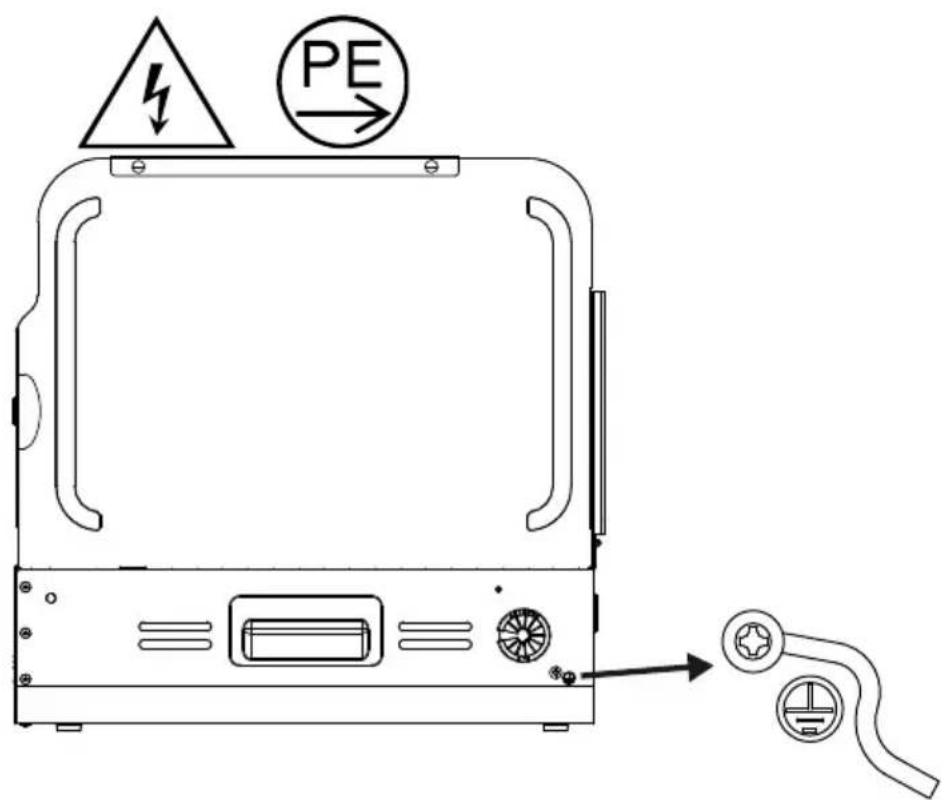
[Caution]
High touch current, Connect to earth before connecting to supply.
(Yellow/Green wire min. 14AWG)
[Note]
Installation of the protective earthing connection of the socket-outlet by a skilled person.
[Attention]
Protective conductor current: Max. 12 port X 5mA = 60mA
- E12
- User Manual
- WARNING
- AVERTISSEMENT
- MISE EN GARDE
- CAUTION
- ATTENTION!
- Federal Communications Commission Statement
- DISCLAIMER
- TRADEMARKS
- COPYRIGHT
- Contact Information
- CONTENTS
- Contact Information....5
- Package Contents.... 1
- Tools Required 2
- Dimensions.... 3
- Diagram.... 3
- Installation 5
- Desk mount (Optional) 13
- Troubleshooting....14
- Specifications....15
- Service and Warranty 16
- Appendix – Earthing....17
- Package Contents
- Tools Required
- Diagram
- Sides
- Top and Bottom
- Front and Back Sides Top and Bottom
- Installation
- Parts list
- A Charging station
- B Desk mount (optional)
- Before installing the charging station
- Step 1: Install door lock cover (Optional)
- [Note]
- Step 2: Connect the power strip to a wall outlet
- 2
- 3
- Step 3: Adapter configuration
- Step 4: Extend and fix the sides of the chassis
- Step 5: Insert dividers into the slots on the shelf
- Step 6: Cable management
- Step 7: Install top cover (Optional)
- Step 8: Secure the charging station (Optional)
- Desk mount (Optional)
- Troubleshooting
- Service and Warranty
- Appendix – Earthing
- [Caution]
- [Attention]
Brand : AVer
Model : E12
Category : Uncategorized