
P30FA - Hi-Fi System Speco Technologies - Free user manual and instructions
Find the device manual for free P30FA Speco Technologies in PDF.


| Product Type | Public Address Amplifier with FM/AM Tuner |
| Model | P30FA |
| Brand | Speco Technologies |
| Rated Output Power | 30W (RMS) |
| Frequency Response | 30Hz – 20kHz |
| Signal-to-Noise Ratio (Mic) | 60dB |
| Signal-to-Noise Ratio (Aux) | 80dB |
| Total Harmonic Distortion | <0.1% at 1kHz rated output |
| Tone Controls | Bass ±10dB at 100Hz, Treble ±10dB at 10kHz |
| Inputs | Mic 1-2 (XLR/1/4", unbalanced 0.5mV/600Ω), Aux (RCA, 100mV/10kΩ), Telephone (200mV/600Ω) |
| Outputs | Line out (1000mV/10kΩ), Speaker: 4Ω/11V, 8Ω/15.5V, 25V/21Ω, 70V/163Ω |
| Tuner Range | FM 87.5-108MHz, AM 530-1620kHz |
| Preset Memory | 30 stations (18 FM, 12 AM), backup up to 45 days |
| Priority/Muting | Mic 1 activates priority circuit muting other inputs |
| Telephone/Music-on-Hold | Telephone input and music-on-hold output for telephone system |
| Power Source | AC 120V or 220V, 60Hz (110V or 240V 50Hz) |
| Power Consumption | 80W |
| Dimensions (W x H x D) | 420 x 88 x 280 mm (16.5 x 3.5 x 11 in) |
| Net Weight | 14 lbs (6.5 kg) |
| Protection | Short-circuit current limiter, thermal cut-out, DC offset, output fuse, AC line fuse |
| Maintenance | Occasional external cleaning with dry cloth; no user-serviceable parts |
| Repairability | Refer servicing to qualified personnel; order parts from Speco Technologies |
Frequently Asked Questions - P30FA Speco Technologies
User questions about P30FA Speco Technologies
0 question about this device. Answer the ones you know or ask your own.
Ask a new question about this device
Download the instructions for your Hi-Fi System in PDF format for free! Find your manual P30FA - Speco Technologies and take your electronic device back in hand. On this page are published all the documents necessary for the use of your device. P30FA by Speco Technologies.
USER MANUAL P30FA Speco Technologies
FOR ASSISTANCE OR REPAIR SERVICE CONTACT:
speco technologies
200 New Highway, Amityville, NY 11701-0726
631-957-8700 · Toll Free: 1-800-645-5516
www.specotech.com
Speco Technologies is constantly developing and improving products.
We reserve the right to modify product design and specifications without
notice and without incurring any obligation. Rev. 4.4.12. We are not responsible for transnational orders.
© 2012 Speco Technologies All rights reserved.
P-30FAPUBLIC
ADDRESSAMPLIFIER
WITH FM/AMTUNER
PROFESSIONAL SERIES
WARNING
TO PREVENT FIRE OR SHOCK HAZARD, DO NOT USE THIS PLUG WITH AN EXTENSION CORD, RECEPTACLE OR OTHER OUTLET UNLESS THE BLADES CAN BE FULLY INSERTED TO PREVENT BLADE EXPOSURE. TO PREVENT FIRE OR SHOCK HAZARD, DO NOT EXPOSE THIS APPLIANCE TO RAIN OR MOISTURE. TO PREVENT ELECTRICAL SHOCK, MATCH WIDE BLADE PLUG TO WIDE SLOT FULLY INSERTED.

This lightning flash with arrowhead symbol, within an equilateral triangle, is intended to alert the user to the presence of uninsulated "dangerous voltage" within the product's enclosure that may be of sufficient magnitude to constitute a risk of electric shock to persons.
CAUTION
RISK OF ELECTRIC SHOCK DO NOT OPEN
Warning: To reduce the risk of electric shock, do not remove cover (or back). There are no user-serviceable parts inside. Refer servicing to qualified service personnel.

The exclamation point within an equilateral triangle is intended to alert the user to the presence of important operating and maintenance (servicing) instructions in the literature accompanying the appliance.
IMPORTANT SAFETY INSTRUCTIONS
-
Read these instructions.
-
Keep these instructions.
-
Heed all warnings.
-
Follow all instructio
-
Follow all instructions.
-
Do not use this answer
-
Do not use this apparatus near water.
-
Clean only with dry cloth.
-
Do not block any ventilation openings. Install in accordance with the manufacturer's instructions.
-
Do not install near any heat sources such as radiators, heat registers, stoves, or other apparatus (including amplifiers) that produce heat.
-
Do not defeat the safety purpose of the polarized or grounding type plug. A polarized plug has two blades with one wider than the other. A grounding type plug has two blades and a third grounding prong. The wide blade or the third prong are provided for your safety. If the provided plug does not fit into your outlet, consult an electrician for replacement of the obsolete outlet.
-
Protect the power cord from being walked on or pinched particularly at the plugs, convenience receptacles, and at the point where they exit from the apparatus.
-
Only use attachments/accessories specified by the manufacturer.
-
Use only with the cart, stand, tripod, bracket, or table specified by the manufacturer, or sold with the apparatus. When a cart is used, use caution when moving the cart/apparatus combination to avoid injury from tip-over.

-
Unplug the apparatus during lightning storm or when unused for long periods of time.
-
Refer all servicing to qualified personnel. Servicing is required when the apparatus has been damaged in any way, such as power supply cord or plug is damaged, liquid has been spilled or objects have fallen into the apparatus, or apparatus has been exposed to rain or moisture, does not operate normally, or has been dropped.
-
This appliance shall not be exposed to dripping or splashing water and no object filled with liquid such as vases shall be placed on the apparatus.
-
Caution-to prevent electrical shock, match wide blade plug to wide slot and fully insert.
-
Please keep a well ventilated environment around the entire unit.
P-30FA
1
SPECIFICATIONS
AMPLIFIER SECTION
Rated Output....30W(RMS)
Frequency Response....30Hz to 20KHz
Signal to Noise Ratio
Mic 1-2....60dB
Aux....80dB
Total Harmonic Distortion (at 1KHz Rated Output)....Less than 0.1%
Tone Controls....Bass +/- 10dB at 10KHz
Treble +/- 10dB at 10KHz
Input Sensitivity/Impedance
Mic 1-2....Unbalanced 0.5mV/600 ohms
Aux....100mV/10K ohms
Telephone....200mv/600 ohms
Line output....1000mV/10K ohms
Speaker Output/Impedance....4 ohms/11V, 8 ohms/15.5V
25V(21 ohms), 70V(163 ohms)
TUNER SECTION
Tuning Range.....FM 87.5MHz-108.0MHz
AM 530KHz-1620KHz
Antenna Input..... FM; 300 ohms Twin Lead or 75 ohms Coax
AM; Single Conductor Lead Wire
Usable Sensitivity FM 2uV, AM4.5uV
Signal to Noise Ratio.....FM 60dB, AM 50dB
Output Level
Line Output Level 775mV (0dBm) Unbalanced
Music on hold Output Level 775mV (0dBm) balanced
Memory Back-up....For 45 days (After AC Power Off)
Protection
(1) Amplifier : Short- Circuit Current Limiter Thermal Cut-Out
(2) Load : DC Offset, Turn- On/Turn- Off Transients (Delay), Output Fuse
(3) Mainframe : AC Line Fuse.
General
Power Source.....AC 120V or 220V 60Hz (110V or 240V 50Hz)
Power Consumption....80W
Dimensions....420(W)x88(H)x280(D)mm
16.5 (W) 3.5 (H) 11 (D) in
Weight(Net)....14LBS(6.5Kg)
NOTE; Specifications and design subject to change without notice.
P-30FA
14
INSTALLATION
1. POWER
The P-30FA Amplifier is to be operated from a AC120V/220V 50/60Hz Power source. The power required for this amplifier is clearly indicated on the back panel.
2. INPUT CONNECTIONS :
Make connections to the microphone (high or low impedance) and auxiliary inputs with the POWER SWITCH in the OFF position and set corresponding volume control to zero to avoid damage to the speakers and the amplifier from hum pickup. (Feedback)
a. MICROPHONE CONNECTIONS. (Refer to figure): A Switchcraft type A3M Microphone connector or equivalent is required for making connections to the Microphone inputs and audio shielded cable is required for all balanced and unbalanced microphone input connections. BALANCED MICROPHONE INPUT CONNECTIONS(MIC. 1/2 only): Using 2 conductor shielded cable, connect each of the two center conductors of the cable to prongs # 1 and #2 of the A3M Microphone connector. Connect the shield of the cable to prong #1 of the A3M Microphone connector.
UNBALANCED MICROPHONE INPUT CONNECTIONS (MIC. #1 & #2): Using single conductor shielded cable, connect the center conductor of the cable to prong #2 of the A3M Microphone connector. Connect the shield of the cable to prong #1 of the A3M Microphone connector.
b. AUXILIARY INPUTS: The auxiliary input receptacles and all other phonotype receptacles, require an RCA Type phono plug (Cinch-jones #13A) or equivalent.
PROFESSIONAL SERIES AMPLIFIER

P-30FA
Welcome
Congratulation and thank you for purchasing PVL15A, 30A series, the multi function commercial amplifiers. These amplifiers are designed to provide quality sound reproduction and to produce the best and highest quality audio at an affordable price. We wish you great enjoyment and satisfaction when using your amplifier, whether you are installation, or reinforcement engineer.
Unpacking and Installation
Although it is neither complicated to install nor difficult to operate your amplifier, a few minutes of your time is required to read this manual for a properly wired installation and familiarity with its many features. Please take great care in unpacking your amplifier and do not discard the carton or other packing materials. These may be needed when moving your amplifier and are required if it ever becomes necessary return your amplifier for service. Never place the unit near radiators, in front of heating vents, in direct sunlight, or in excessively humid or dusty location to avoid damage. Connect your complementary components as illustrated in the following page.
Features
FM/AM TUNER WITH MEMORY
The memory stores up to 30 memories (18 FM Stations & 12 AM Stations).
VERSATILE AND CONVENIENT
3 inputs from Mic1, Mic2 and Aux/CD are provided and mixed. Mic inputs for both XLR and 1/4" phone plugs.
MUTING FOR PRIORITY
Input to Mic 1 will automatically activate the priority circuit which temporarily mutes signals from other inputs, tuner or tape.
TELEPHONE INPUT & MUSIC- ON HOLD
This model has the function of telephone input and music-on hold to connect with telephone system.
SERVICE AND MAINTEANCE
The use of solid state circuitry and advanced manufacturing techniques built in your unit results in very high reliability, and under normal operat - ing conditions, your amplifier should not require service other than an occasional external cleaning.
Keep the original carton and packing material to use if you need to return your unit for service. Merchandise to be returned for out-of-warranty or in-warranty repair requires prior written authorization. Please write or call toll free 1-800-645-5516 or in METRO NEW YORK 631-957-8700. We request you enclose a packing slip with the shipment that has a complete description of the problem and dated proof of purchase, if in warranty, when shipping the unit to the factory, please be sure to pack the unit well enough to withstand rough handling and use return shipping label supplied by Speco techologes. Ship the unit FREIGHT PREPAID, TO :
200 NEW HIGHWAY- P.O. BOX 726
AMITYVILLE, NEW YORK 11701-0726
When ordering parts, please give a description or the part number, if available. Direct your order to the PARTS DEPARTMENT.
We will then advise total cost for remittance including shipping and handling.

Speco technologies
200 New Highway P.O. Box 726
Amityville, N.Y. 11701-0726
U.S.A.
TEL:631-957-8700, 1-800-645-5516
www.specotech.com
P-30FA 3
INSTALLATION OF SPEAKERS
| MODEL | 4 OHM | 8OHM | 25V | 70V |
| P-30FA | 11V | 15.5V | 21 OHM | 163 OHM |
Installation of the Speaker
When you connect the speaker, remove the AC cord from AC INLET. And connect the speakers according to the connecting way as below after selecting the suitable terminal.
FOR LOW IMPEDANCE WIRING

4 OHMS WIRING

8 OHMS WIRING
FOR HIGH IMPEDANCE WIRING

25V LINE WIRING

70V LINE WIRING
*Be sure that total impedance is not less than rated impedance. (See upper chart.)
P-30FA
12
CONNECTIONS
Typical input and output wiring is shown in figure.

P-30FA
11
DESCRIPTION
The P-30FA is a rugged, dependable, 30W AM/FM Tuner public address amplifier. This unit contains features generally found in much higher priced models and can be used with virtually any program source. The P-30FA feature 2 microphone inputs. The 2 microphone inputs may be used for high or low impedance microphone. HI-Z microphone (over 1k ohm) Input is for unbalanced operation Wireing LO-Z microphone (up to 600 ohm) minput may be operated balanced or unbalanced. Mic-1 input may be use for priority paging. The unit has AUX input for use with radio tuners, tape decks or other high impedance, high output devices. The inputs are controlled by their individual volume controls.
Outputs are provided for 4 and 8 ohms speakers and 25V and 70V constant voltage lines.
CONTROLS
FRONT PANEL CONTROLS
a. The POWER SWITCH :
The Power switch is located at the extreme right hand side of the front panel. When switching the amplifier on, the red switch will become illuminated
b. MICROPHONE VOLUME CONTROL :
Rotating the microphone controls clockwise increases the gain of the microphone inputs.
c. TUNER VOLUME CONTROL
You can adjust the volume level of AM/FM tuner output with this controls
d. AUX VOLUME CONTROL :
Rotating the AUX controls clockwise increases the gain of the AUX input.
e. TONE CONTROL
Rotating the Tone control clockwise increases the Bass/Treble and counter clockwise increase the Bass/Treble. Tone is flat at center.
PRIORITY AND MUTING (VOX)
The Mic-1 priority will activate the priority circuit which temporarily mutes signals from other inputs,
P-30FA
4
CONTROLS
1. FRONT PANEL CONTROLS

- POWER SWITCH
When powering the amplifier on, the switch will illuminate.
- MASTER VOLUME CONTROL
This control is used for adjusting the volume of all inputs simultaneously
- TREBLE CONTROL
This control is used for adjusting +/- 10db high frequency sound(10KHz)
- BASS CONTROL
This control is used for adjusting +/- 10db low frequency sound(100Hz)
- TUNER VOLUME CONTROL
You can adjust the volume livel of AM/FM tuner output with this controls
- AUX VOLUME CONTROL
Rotating the AUX controls clockwise increases the gain of the AUX input.
- MIC VOLUME CONTROL
Rotating the microphone controls clockwise increases the gain of the microphone inputs.
- LED LEVEL METER
The LED display indicates the output level in 3dB increments.
- TUNER DISPLAY
Indicates frequency of station selected.
Connection of the Antenna and
the Ground Cable
AM/FM RECEIVING ANTENNA
AM/FM broadcasting is weakened by hills and valleys, around tall buildings and in iron-reinforced buildings.
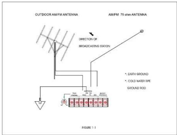
INSTALLATION OF FM ANTENNA USING 300 OHM TWIN LEAD
Connect the leads from the antenna of the terminals marked 300 ohm. Rotate antenna to direction of strongest reception. (Fig. 1-1)
INSTALLATION OF AM/FM ANTENNA USING COAXIAL CABLE (75 OHM)
Connect center conductor to 75 ohm terminal and shield to GND.
INDOOR ANTENNA
In regions where AM/FM broadcasting is heard comparatively well due to the near distance of stations, you can receive broadcasting of good quality by using a T-type (FM dipole) antenna. Mount the antenna at the best location for reception after connecting it to the terminals marked 300 ohm. (Fig. 1-1)
6. ANTENNA TERMINALS
AM/FM Terminal : You can connect 75 ohm coaxial cable or 300 ohm TV cable according to the antenna system you have. GND Terminal : Ground this terminal if noise or hum is present and when using an outdoor antenna.
7. LINE OUT JACK
Permits auxiliary equipment to be patched from the output of preamplifier.
8. TELEPHONE IN CONTROL
This control is used to adjust the level of the telephone input signal. NOTE: If the output of your telephone system is higher than 1V/600 ohm, you must use a line matching transformer. (SPECO Model TLT-1)
9. TELEPHONE IN TERMINALS
These terminals are for connection to telephone system for paging. NOTE: When there is a paging signal through this terminal, all other input signals except AMP IN are muted.
10 MUSIC- ON HOLD TERMINALS
These terminals are for connecting to the telephone system. NOTE: When the tuner is turned on, the tuner output signal is always supplied to these terminals and is not affected by master volume or tuner volume.
WIRING GUIDE
Choose input wire and connectors
HCA recommends using pre-built or professionally wired balanced line, 22 to 24 gauge cables. Figure shows connector pin assignments for wiring. The RCA input connections can also be used for unbalanced inputs
MIC BALANCED WIRING GUIDE
Input

output

Balances 1/4" Connector
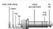
Unbanded 1/4" Connector

Input output pin no:
1=ground/shield
2=hot(+ve)
3=cold(-ve)
For connection of balanced and unbalanced plugs, ring and sleeve have to be bridged at the stereo plug
For unbalanced use pin 1 and 3 have to be bridged
TUNER

10. TUNER POWER SWITCH
When powering the tuner on, the switch will LCD display.
11. UP/DOWN TUNING CONTROL
These buttons are used to manually tune stations.
12. BAND SELECTOR AM OR FM
This switch is used for selecting AM 1, or 2, or FM 1, 2, or 3.
13. SCAN/UP MONITOR
When SCAN/UP button is pressed, the frequency is scan up by one channel step with station detection. If a valid signal has detected, the current frequency is blinked each 500m sec within 5 seconds. If this case, SCAN/UP button is pressed, SCAN function is released and the current frequency in maintained.
14. MEMORY SWITCH
1). Directly accesses the preprogrammed station within the selected frequency band.
2). It performs preset memory read/write function.
• WRITE Operation
One of the M1-M6 button is pressed for more than 2 seconds, current frequency is stored to corresponding memory area.
- READ Operation
One of the M1-M6 button is pressed for less than 2 seconds, read the corresponding preset memory. - When write operation, it performs 0.5sec mute operation.
15. LOCAL-DX
Local-long distance reception
16. MUTE
MUTE on/off control button.
When "MUTE" is displayed on LCD panel, all outputs are muted.
17. A/PS (AME/PSCAN)
Preset memory scan auto store memory button.
- When A/PS button is pressed for less than 1 sec. it performs preset memory scan function.
- When A/PS button is pressed for more than 1 sec. it performs auto. store memory function.
1). Preset memory scan function descriptions
Reading preset memory in regular frequency for 5 seconds each.
Ex1) Current receiving frequency : FM1, CH3.

flowchart
graph TD
    A["Button On"] --> B["M3 → M4 → M5 → M6"]
    C["FM1"] --> D["M1 → M2 → M3 → M4 → M5 → M6"]
    E["FM2"] --> F["M1 → M2 → M3 → M4 → M5 → M6"]
    G["FM3"] --> H["M1 → M2 → M3 → M4 → M5 → M6"]
    I["FM1"] --> J["M1 → M2 → M3"]
    K["PSCAN Operation Stop"] --> L["↑"]
- If A/PS button is pressed aging during preset memory scan operation, it stop preset memory scan operation and maintain the current frequency.
2). Auto store memory function descriptions
During SEEK UP operation with station detection, if any station is detected, then this detected station is automatically stored to the corresponding preset memory area in regular frequency.
- Current receiving frequency is preset memory: From current channel to M6.
- Current receiving frequency is not preset memory: From M1 to M6.
- During auto store memory, output signals are muted and flashing channel number(1Hz, duty) till finished this function.
- When this operation is finished, it performs preset memory scan operation for one time.
18. BACK-UP BATTERY ON/OFF PIN SWITCH
The unit has a back-up battery so that the preset memory are kept stored even after power off.
This back up battery is deactivated when delivered ex factory to prevent a slow
discharge until the unit will be installed. To activate the back up battery,
place the pin switch from OFF position to ON position on PCB board.
19. BACKUP MEMORY
This memory is valid 45days (After AC Power Off)
P-30FA 7
CONTROLS
1. BACK PANEL CONTROLS

1. AC INLET
This is the AC INPUT for the AC INPUT CORD. CAUTION : Voltage Check !
2. FUSE HOLDER
This fuse holder contains the AC power fuse. Replace only with same type fuse when it is blown. If it continuously blows, stop replacing fuse and referservicing to qualified personnel.
| VOLTAGE | AC120V | AC220V |
| FUSE RATING | 1A/250V | 0.5A/250V |
3. MIC-1/2 INPUT
These are XLR or PL55 input and are designed for electrical balanced circuitry (XLR Mic-1, PL55 Mic-2)
4. AUX INPUT
The sound source (from CD Mp3 cassette deck etc.) is connected to this RCA input
5. SPEAKER OUTPUT TERMINALS
These terminals are for speaker connection. You can select 4 ohm or 8 ohm or higher impedance lines 25V and 70V Be sure not to make the total impedance less than rated impedance on 25V or 70V. 4 ohm and 8 ohm must be matched exactly.
| MODEL | 4 OHMS | 8 OHMS | 25V | 70V |
| P-30FA | 11V | 15.5V | 21 OHM | 163 OHM |
* Be sure not to make the total impedance less than rated impedance.
P-30FA
8
- WARNING
- CAUTION
- IMPORTANT SAFETY INSTRUCTIONS
- SPECIFICATIONS
- INSTALLATION
- POWER
- INPUT CONNECTIONS :
- PROFESSIONAL SERIES AMPLIFIER
- Welcome
- Unpacking and Installation
- Features
- SERVICE AND MAINTEANCE
- Installation of the Speaker
- CONNECTIONS
- DESCRIPTION
- CONTROLS
- FRONT PANEL CONTROLS
- PRIORITY AND MUTING (VOX)
- FRONT PANEL CONTROLS
- ANTENNA TERMINALS
- LINE OUT JACK
- TELEPHONE IN CONTROL
- TELEPHONE IN TERMINALS
- MUSIC- ON HOLD TERMINALS
- WIRING GUIDE
- Choose input wire and connectors
- MIC BALANCED WIRING GUIDE
- TUNER POWER SWITCH
- UP/DOWN TUNING CONTROL
- BAND SELECTOR AM OR FM
- SCAN/UP MONITOR
- MEMORY SWITCH
- LOCAL-DX
- MUTE
- A/PS (AME/PSCAN)
- BACK-UP BATTERY ON/OFF PIN SWITCH
- BACKUP MEMORY
- BACK PANEL CONTROLS
- AC INLET
- FUSE HOLDER
- MIC-1/2 INPUT
- AUX INPUT
- SPEAKER OUTPUT TERMINALS
Brand : Speco Technologies
Model : P30FA
Category : Hi-Fi System