Platinum Smart-Heat BH0320007 - Heating Bromic - Free user manual and instructions
Find the device manual for free Platinum Smart-Heat BH0320007 Bromic in PDF.


| Product Type | Electric Infrared Patio Heater |
| Brand | Bromic |
| Model | Platinum Smart-Heat BH0320007 |
| Power | 1500W |
| Voltage | 120V AC, 60Hz |
| Heating Element | Quartz infrared tube |
| Coverage Area | Up to 150 sq. ft. |
| Dimensions (H x W x D) | 26.5 x 6.5 x 4.5 inches |
| Weight | 11.5 lbs |
| Mounting Type | Wall-mount or ceiling-mount (bracket included) |
| Control | Remote control and touch panel |
| Heat Settings | 2 power levels (High/Low) |
| Safety Features | Tip-over shut-off, overheat protection, IP65 weather resistant |
| Housing Material | Aluminum with tempered glass |
| Certifications | ETL, CSA |
| Warranty | 2 years limited |
| Included Accessories | Heater, remote control, mounting hardware, user manual |
| Power Cord Length | 6 ft |
| Color | Black / Silver (depending on variant) |
| Energy Saving | Zone heating – heats people and objects directly |
Frequently Asked Questions - Platinum Smart-Heat BH0320007 Bromic
User questions about Platinum Smart-Heat BH0320007 Bromic
0 question about this device. Answer the ones you know or ask your own.
Ask a new question about this device
Download the instructions for your Heating in PDF format for free! Find your manual Platinum Smart-Heat BH0320007 - Bromic and take your electronic device back in hand. On this page are published all the documents necessary for the use of your device. Platinum Smart-Heat BH0320007 by Bromic.
USER MANUAL Platinum Smart-Heat BH0320007 Bromic
PLATINUM SMART-HEAT™ ELECTRIC HEATER SERIES II BY BROMIC
INSTALLATION, INSTRUCTION AND SERVICE MANUAL
AVAILABLE IN 2300W & 3400W VERSION
| PROP. 65 WARNING FOR CALIFORNIA RESIDENTS |
| Cancer and Reproductive Harm - www.P65Warnings.ca.gov |
| AVERTISSEMENT PROP. 65 POUR LES RESIDENTS DE LA CALIFORNIE |
| Cancer et Troubles de l'appareil reproducteur - www.P65Warnings.ca.gov |
| AVERTISSEMENT PROP. 65 PARA LOS RESIDENTES DE CALIFORNIA |
| Cancer y Daño Reproductivo - www.P65Warnings.ca.gov |
Original Instructions
This manual contains important information about the installation, operation, and maintenance of Platinum Smart-Heat™ Electric Heaters. Please pay close attention to the important safety information shown throughout this instruction manual. Any safety information will be accompanied by the following safety alert symbols:
⚠️ DANGER, ⚠️ WARNING, ⚠️ IMPORTANT
- READ THIS MANUAL CAREFULLY before installing or servicing this product.
- Improper installation, operation, or maintenance can result in death, severe injury, or property damage.
- This appliance is intended for fixed installation with 220-240V AC single-phase power supply.
- Installation MUST be carried out by a licensed and authorised technician in accordance with local electrical codes.
- This product is intended for domestic and commercial use.
• International Registered Designs Pending.
CONTENTS
IMPORTANT NOTES & WARNINGS 4
PRODUCT OVERVIEW 5
PRODUCT DESCRIPTION 5
SPECIFICATIONS 5
PRODUCT FEATURES 5
HEATER INSTALLATION INSTRUCTIONS 6
CEILING & WALL MOUNTING 6
CEILING RECESS 9
TUBE SUSPENSION 10
ELECTRICAL INSTALLATION 11
SERVICING 11
TROUBLESHOOTING 11
IMPORTANT NOTES AND WARNINGS

WARNING
IMPORTANT - Installation MUST be carried out by a licensed and authorised person.
- Improper installation, adjustment, or alteration and Failure to follow the warnings and instructions in this manual could result in severe personal injury, death or property damage.
- The manufacturer is not responsible for any damage that could happen from improper use. The manufacturer emphasises that this appliance should be used in a responsible manner and that all procedures, warnings, and safety instructions contained in this booklet be followed strictly.
- The installer is to ensure that the requirements of the local authority, local electrical installation code, municipal building codes, and any other relevant statutory regulations are carried out.
- Do not place articles on or against this appliance.
- To reduce the risk of fire, do not store or use gasoline or other flammable vapors and liquids in the vicinity of the heater.
- This Installation, Operation and Service manual should not be removed from the site of installation. Installer should leave manual with the customer for future reference.
- A minimum safety distance of 39.4" should always be left in front of the appliance.
- This unit must be mounted at a minimum of 72" above the floor (wall mounted) and 96" (ceiling mounted).
- The appliance must not be located directly below or in front of a wall electricity socket. This is because the heat radiated from the appliance may damage the electricity outlet or plug.
- This appliance is not intended for use by persons (including children) with reduced physical, sensory or mental capabilities, or lack of experience and knowledge, unless they have been given supervision or instruction concerning use of the appliance by a person responsible for their safety.
- Heaters are not intended to be installed in wardrobes.
- Extreme caution is necessary when any heater is used by or near children or invalids and whenever the heater is left operating and unattended.
- Children and adults should be alerted to the hazards of high surface temperatures and should stay away to avoid burns, clothing ignition, or other serious personal injury
- This heater is hot when in use. To avoid burns, do not let bare skin touch hot surfaces. Keep combustible materials, such as furniture, pillows, bedding, papers, clothes, etc. and curtains at least 3 feet (1m) from the front of the heater and keep them away from the sides and rear
- Keep packaging materials out of reach of children
- Do not spray aerosols or flammable materials in the vicinity of this appliance while it is in operation
- Installation and repair must be carried out by a qualified & licenced service person only. The heater should be inspected before use and at least annually serviced & inspected by a qualified & licenced service person.
- Do not perform maintenance until heater has been turned off,
power disconnected, and heater temperature has cooled to room temperature.
- Certain materials or items, when stored under or near the appliance, will be subjected to radiant heat and could be seriously damaged. Combustible materials eg. walls, floors, furniture, fixtures and plants must be kept a minimum of 3 ft from the heater.
- Clothing or other flammable materials should not be hung from the heater or placed on or near the heater.
- Be sure the heater is not facing the ceiling or flammable or combustible substances/materials.
- This radiant heater is NOT intended to be installed on recreational vehicles and/or boats.
- Do not attempt to alter the unit in any manner.
- Remove transit protection before use.
- Never operate the heater in an explosive environment such as areas where petrol or other flammable liquids or vapours are stored.
- Do not paint any surface of the heater.
- Check for damage to the appliance regularly. The heater must not be used if the black radiant panel or any other part of the heater is damaged. If damage to the appliance is suspected, discontinue use immediately and contact the supplier or qualified person to repair.
• After unpacking, make sure the appliance shows no signs of visible damage or tampering. If the appliance appears damaged, contact the place of purchase for assistance. - This appliance must only be used on a 220-240V AC Single phase power supply.
- This appliance must only be used on a 220-240V AC Single phase power supply.
- Do not touch the heating surface at any time, even when the heater is turned off and has cooled down.
- Do not touch the heater with wet hands at any time.
- If the appliance has not been used, or will not be used, for a long period of time, disconnect power supply
- At the end of this product's useful life, it must not be disposed of as domestic waste, but must be taken to a collection centre for waste electrical and electronic equipment. It is the user's responsibility to dispose of this appliance through the appropriate channels at the end of its useful life.
Failure to do so may incur the penalties established by laws governing waste disposal. Proper differential collection, and the subsequent recycling, processing and environmentally compatible disposal of waste equipment avoids unnecessary damage to the environment and possible related health risks, and also promotes recycling of the materials used in the appliance.
For further information on waste collection and disposal, contact your local waste disposal service, or the place of purchase.
- In case of direct connection to a supply line, a bipolar circuit breaker with contact opening distance of at least 3mm must be fitted upstream from the supply line. Contact an authorised
IMPORTANT NOTES AND WARNINGSCONTINUED ...
service technician if you are unsure if you have a circuit breaker installed on the premises.
- Do not install the heater directly near a bathtub, shower or swimming pool. Any switches or controls must not be within reach of a person in the bathtub, shower or swimming pool.
- To maintain Ingress Protection Rating (IPX4), only IP44 rated conduit fittings should be used for electrical installation.
- A means for disconnection of the heater must be incorporated in the fixed wiring according to the local electrical codes.
- If the supply cord is damaged, it must be replaced by an authorised and licenced person in order to avoid a hazard.
- Do not bend the electrical connection to the power supply.
- Keep the cable away from sharp edges during handling and installation.
-
Do not pull on the cable or subject it to traction force.
-
Avoid physical shock & impact to the heater when handling.
- Do not apply any pressure on the glass surface.
- Keep the electrical connection area to the power supply clean.
- Ensure that the heating unit is not directly exposed to rain or water contact.
- Use this heater only as described in this manual. Any other use not recommended by the manufacturer may cause fire, electric shock, or injury to persons.
- If any part of the instruction manual is missing or damaged, contact Bromic for a complete version.
- If you are unsure of any aspect of the installation, contact Bromic for advice.
PRODUCT OVERVIEW
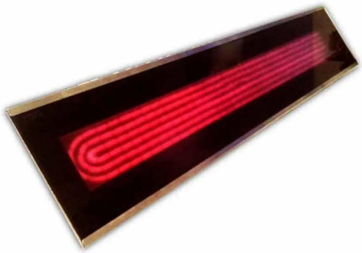
The Platinum Smart-Heat ™ Electric is designed to provide efficient spot heating for commercial and residential applications.
The heaters are built with corrosion resistant materials, have electrical approval in North America and are rated to IPX4 water Ingress Protection. Making the Platinum Smart-Heat™ Electric the perfect solution for a variety of indoor and outdoor heating applications.
| SPECIFICATIONS | |||
| Model | Platinum Smart-HeatTM Electric II | ||
| Part no. | Black | BH0320003 | BH0320005 |
| White | BH0320007 BH0320008 | ||
| Heat Output (Watts) 2300W 3400W | |||
| Power connection required (Volts/Amps) | 220-240V - A.C.- 50/60Hz - 9.6A | 220-240V - A.C. -50/60Hz - 14.2A | |
| Dimensions (WxHxDmm) | 840 x 182 x 54 mm(33.0 x 7.0 x 2.0") | 1275 x 182 x 54 mm(50.2 x 7.0 x 2.0") | |
| Weight (kg) 7.5kg (16.5lbs) 10kg (22lbs) | |||
| Finish Brushed Stainless Steel 304 | |||
| Approval | Intertek: 5001799 | ||
PRODUCT FEATURES
■ Ultra-thin and stylish design
■ Efficient directional spot heating
- Heat Zones — one or more heaters can be switched on and off simultaneously from a single remote-located switch
- Platinum Smart-Heat™ Electric Heaters can also be integrated into smart control systems
Wind resistant & IPX4 water protection rating
- Suitable for outdoor and indoor heating applications such as restaurants, cafes, bars and clubs, factories, office spaces, designated smoking areas, public areas, hotels and more
- Standard Mounting - included with heater
- Optional Mounting - purchased separately from heater:
- Ceiling Recess
- Tube Suspension
HEATING INSTALLATION INSTRUCTIONS
CEILING & WALL MOUNTING
- Heaters must be installed according to the minimum installation clearances shown in these diagrams.
- Heaters must be away from the fourth wall.

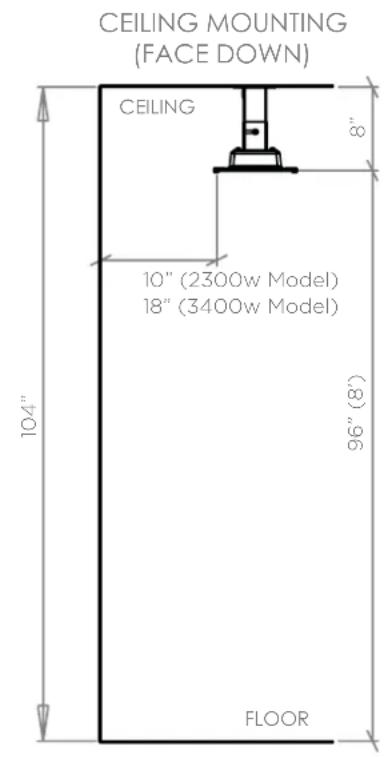


WARNING
MINIMUM DISTANCE BETWEEN HEATERS MEASURED FROM EDGE OF HEATER MUST BE AT LEAST 20"


This heater MUST be permanently installed by an authorised/licenced person. Do not perform maintenance, or carry out installation or assembly procedure while electrical power is switched on. Wait 2 hours after switching off the heater before handling.

WARNING - Outdoor InstallationWARI
Ensure that the heating unit is not directly exposed to rain or water contact. For longest product life and to maintain product appearance, mount heater under cover and protect from rain and weather.
HEATING INSTALLATION INSTRUCTIONS CONTINUED...
OPTION 1
To exit the cable through the side of the wall mounting bracket, start from step 1.
-
Unscrew and remove plug-in wall bracket (a).
-
Attach extra supplied cable gland into the same hole from the outside of the bracket. Fasten in place
with the metal cable gland nut from inside the bracket
(b).
NOTE: Continue to step 3 below
OPTION 2
To exit the cable through the wall bracket directly into your ceiling or wall cavity, start from step 3.
- Attach mounting bracket to ceiling or wall using fasteners appropriate for the surface (c). Ensure the bracket is firmly secured with fasteners in all 4 holes before proceeding. For wall mounting, ensure the silver plug or cable gland (a) is facing upwards.

WARNING: The bracket mounting surface T be protected from rain. This is necessary to water entering the bracket & maintain IPX4 g.
-
Ensure M6x0.6" screws are inserted into both sides of heater bracket with 6mm of the threaded shaft exposed under the screw head (d).
-
For cable exit through the side of the wall bracket: feed heater power cable through cable gland in wall bracket (e).
NOTE: This is easier when the top of the cable gland is
completely removed when feeding the cable through the bracket. The cap can then be inserted onto the cable for fastening.
-
For cable exit into the ceiling or wall cavity: make a small hole in the black foam on the bracket mounting surface to pass the cable through. Make electrical connection now or feed cable into wall or ceiling for subsequent connection (f). This is described under 'Electrical Installation' on page 11.
-
Insert heater bracket into mounting bracket by hooking M6 screws into place in mounting slots (g).

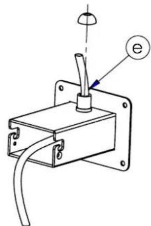
Optional: Cable exit through wall bracket

Wall mount
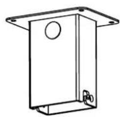
Ceiling mount

Cable exit into wall cavity
HEATING INSTALLATION INSTRUCTIONS CONTINUED...
- To fix heater at desired angle, fully insert M3x0.4" positioning screws (included with wall bracket) on both sides of mounting bracket whilst holding heater in the desired position (h). The heater can positioned straight, or be angled 30deg either way.
- Fit the smaller cover over the heater bracket so that the slots pass over the shafts of the M6x0.6" mounting screws (i). Fit the larger cover over the smaller cover in the same way from the opposite side of the bracket (j). Use angled covers if heater is angled. Use straight covers if heater is not angled.
- Tighten mounting M6 screws firmly, ensuring covers fit snugly against the bracket on all sides (k).


HEATING INSTALLATION INSTRUCTIONS CONTINUED...
CEILING RECESS (SOLD SEPARATELY)

WARNING
Instructions below are suitable for ceiling surfaces 0.4-1.2" thick. For ceiling surfaces thicker than 1.2", contact Bromic for alternative installation options.

WARNING
The heater shall, under no circumstance, be covered with insulating material or similar material.

WARNING
The heater must be completely protected against water contact from above.

WARNING
Joists, beams and rafters shall not be cut or notched to install the heater.

WARNING
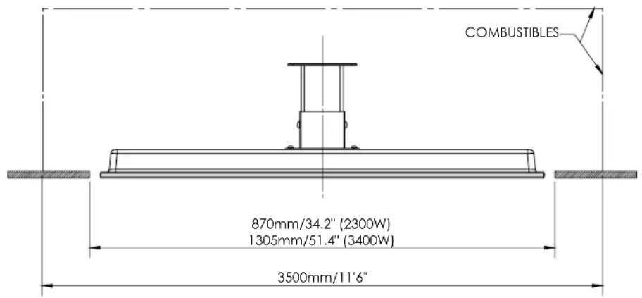
Individual clearances to combustibles are fixed minimums to each individual option and cannot be combined between Option 1 and Option 2

WARNING
MINIMUM DISTANCE BETWEEN HEATERS MEASURED FROM EDGE OF HEATER MUST BE AT LEAST 20"
CLEARANCE TO COMBUSTIBLES OPTION 1
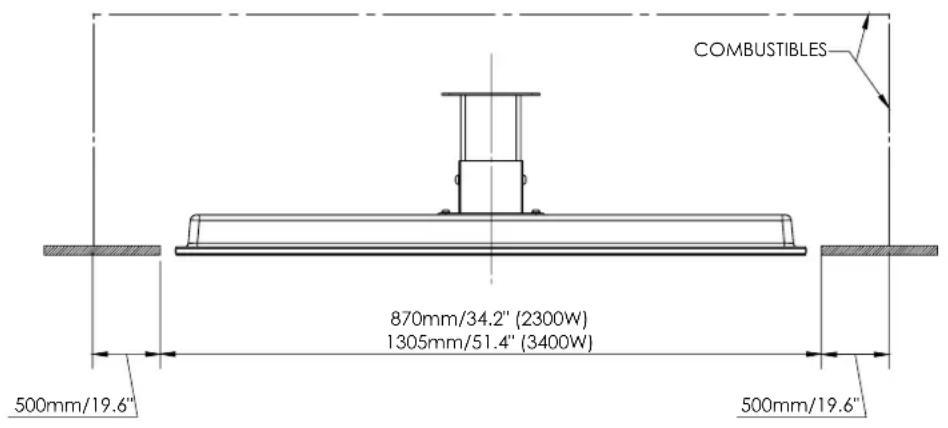
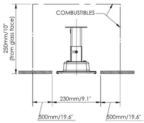
CLEARANCE TO COMBUSTIBLES OPTION 2

HEATING INSTALLATION INSTRUCTIONS CONTINUED...
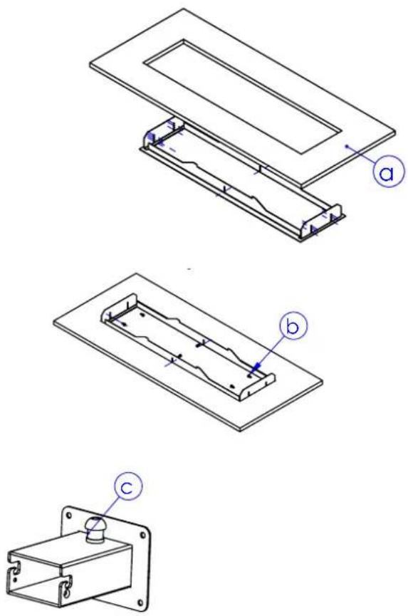
- Prepare ceiling cut-out with dimensions from images on P.9 to fit ceiling recess frame (a). Heater must be installed with heater surface at least 2400mm above the floor level, with 500mm clearance to the nearest wall on all sides of the heater. Minimum distances to combustibles within cavity must be according to only one of the two options shown.
- From below, bring ceiling frame up and into ceiling cutout. Fasten ceiling frame into cut-out at both ends and centre using appropriate screws (b). Which locator hole to use is dictated by the thickness of the ceiling surface. The fastening screws must be inserted into a strong material that can easily support the weight of the heater. Your installation may require re-enforcing before the frame can be safely installed.
- Unscrew and remove plug-in wall bracket. Attach extra supplied cable gland into the same hole from the outside of the bracket. Fasten in place with metal cable gland nut from inside the bracket (c).
- Feed heater power cable through cable gland from inside of wall bracket (d).
- Ensure M6x14mm screws are inserted into either side of heater bracket with 6mm of the threaded shaft exposed under the screw head. (e).
- Insert heater bracket into mounting bracket by hooking M6 screws into place in mounting slots (f).
- Fix heater to bracket in straight position using M4x10mm positioning screws on either side of mounting bracket (g). Ensure M6 screws are sitting fully in the mounting slots (as if the heater were hanging from the wall bracket).
- Fit the smaller, straight cover over the heater bracket so that the slots pass over the shafts of the M6x14mm mounting screws (h). Fit the larger cover over the smaller cover in the same way from the opposite side of the bracket (i).
- Tighten mounting screws firmly, ensuring covers fit snugly against the bracket on all sides (j).
- Firmly tighten cable gland in wall bracket so that cable does not move when pulled.


HEATING INSTALLATION INSTRUCTIONS CONTINUED...
CEILING RECESS (SOLD SEPARATELY)
- Attach the bracket end-cap to the wall bracket using the 4 M5 screws and nuts provided (k).
- Carefully remove the 4 M5 screws fastening the heater mounting bracket to the back of the heater. Be careful not to move or put any force on the bracket. Place the 2 halves of the ceiling recess mounting plate over the screwholes. Re-insert the screws & tighten firmly. (I)
- Make electrical connection from heater to power supply. This is described under 'Electrical Installation'
- Raise one long side of heater up into ceiling frame cavity & then raise whole heater into cavity. (m)
- Rotate the heater into level position in the ceiling cavity (n) and then lower down onto the ceiling frame. Ensure the heater brackets are hooked over the ceiling frame and sitting in the slots on both sides. (o)

TUBE SUSPENSION
- Heater must be installed with heater surface at least 94" above the floor level.
- Installation is identical to 'Ceiling & Wall Mounting' above.
- Use ceiling bracket (sold separately) instead of mounting bracket supplied with heater.
- Ceiling pole only suitable for ceiling mounting. Do not wall mount.


ELECTRICAL INSTALLATION

WARNING
This heater MUST be permanently installed by an authorised/licenced person. Do not perform maintenance, or carry out installation or assembly procedure while electrical power is switched on. To disconnect heater, turn off power to heater circuit at main disconnect panel.

WARNING
ELECTRICAL SHOCK HAZARD! Serious injury or death may occur. Disconnect from electrical supply before installing or servicing this heater. Read and follow installation clearance requirements outlined in this manual. The appliance MUST be connected to a properly grounded electrical source.
ELECTRICAL INSTALLATION
- Check product label for correct voltage and wattage to ensure sure power source conforms to the heaters requirements.
- The power cable must positioned away from & protected from the enclosure of the heater.
- Make all connections in accordance with local electrical code regulations. For outdoor installation, all connections must be made in accordance with local electrical code regulations for outdoor wiring. Only use wiring components approved for outdoor use with minimum IPX4 rating.
For wiring instructions using Bromic Platinum Smart-Heat Electric Wireless Dimmer BH3130011-1 or ON/OFF Control BH3130010-1 refer to instructions provided with controller.
IMPORTANT: Electronic dimmer controls generate heat during operation. For Bromic heaters installed Bromic Smart-Heat Electric Wireless Dimmer BH3130011-1 or ON/OFF Control BH3130010-1 it is essential to ensure dimmers are mounted in a clean, dry and well ventilated position with clearance on all sides. It must be ensured the dimmers are not installed in a confined space, close to other heat generating appliances or in the case of a multi-dimmer installation, not too close together. Dimmers must remain cool at all times. Please consult Bromic dimmer installation instructions for further details or for further questions please contact Bromic technical support services.
SERVICING

WARNING
ELECTRICAL SHOCK HAZARD!
Serious injury or death may occur. Disconnect from electrical supply before servicing this heater.

WARNING
Servicing and maintenance MUST be carried out by an authorised and licenced service person only. Do not operate any heater after it malfunctions. Disconnect power at service panel and have heater inspected by a reputable electrician before reusing.

WARNING
If the supply cord is damaged, it must be replaced by Bromic, a service agent of Bromic or similarly qualified persons in order to avoid a hazard. Contact Bromic for further information on replacement of the supply cord.
MAINTENANCE
Ensure that the heating unit is not directly exposed to rain or water contact. For longest product life, and to maintain product appearance, mount heater under cover and protect from rain and weather whenever possible.
The exterior housing of the heater should be cleaned regularly. To clean the appliance; ensure heater is off, and has been off for at least 2 hours after operation, before wiping off any dirt/dust with a soft damp cloth.
Salt in the air can cause rusting of metal, especially at locations near the coast. Additional cleaning of the heater with a soft damp cloth fortnightly will aid in maintaining the product's appearance.
TROUBLESHOOTING
| SYMPTOM POSSIBLE CAUSE (S) CORRECTIVE | ACTION | |
| No heat 1. Improper connection 1. Check connection to power supply | ||
| Not enough heat 1. Heater too small for application2. Heater mounted too high or too far | 1. Add additional heater(s)2. Decrease mounting height or distance | |
| Too much heat 1. Heater too large for application2. Heater mount too low or too close | 1. Replace with smaller heater2. Increase mounting height or distance | |
- PLATINUM SMART-HEAT™ ELECTRIC HEATER SERIES II BY BROMIC
- INSTALLATION, INSTRUCTION AND SERVICE MANUAL
- CONTENTS
- IMPORTANT NOTES AND WARNINGS
- WARNING
- IMPORTANT NOTES AND WARNINGSCONTINUED
- PRODUCT OVERVIEW
- PRODUCT FEATURES
- HEATING INSTALLATION INSTRUCTIONS
- CEILING & WALL MOUNTING
- WARNING - OUTDOOR INSTALLATIONWARI
- HEATING INSTALLATION INSTRUCTIONS CONTINUED
- OPTION 1
- OPTION 2
- CEILING RECESS (SOLD SEPARATELY)
- TUBE SUSPENSION
- ELECTRICAL INSTALLATION
- SERVICING
- MAINTENANCE
- TROUBLESHOOTING
Brand : Bromic
Model : Platinum Smart-Heat BH0320007
Category : Heating