
SL-650QDP-BT - Uncategorized OPTEX - Free user manual and instructions
Find the device manual for free SL-650QDP-BT OPTEX in PDF.


| Product Type | Photoelectric Detector (Outdoor Infrared Beam) |
| Model | SL-650QDP-BT |
| Brand | OPTEX |
| Detection Range | 200 m / 650 ft (maximum) |
| Detection Method | Quad infrared beam interruption detection |
| Beam Frequency | 4 channels selectable |
| Interruption Time | 50 / 100 / 250 / 500 ms (4 steps) |
| Power Source | 10.5 – 30 VDC (normal) |
| Current Draw (Normal) | 22 mA (T: 11 mA, R: 11 mA) |
| Output - Alarm | Form C relay: 30 VDC, 0.2 A |
| Output - Tamper | N.C. contact output: 30 VDC, 0.1 A |
| Output - D.Q. | Form C relay: 30 VDC, 0.2 A |
| International Protection | IP65 |
| Operating Temperature | -35°C to +60°C (-31°F to +140°F) |
| Operating Humidity | 95% max |
| Alignment Angle | ±90° horizontal, ±10° vertical |
| Dimensions (H x W x D) | 448 x 79 x 96 mm (17.6 x 3.1 x 3.8 in) |
| Weight (Transmitter + Receiver) | 2400 g (excluding accessories) |
| Beam Power Control | Manual selector: NORMAL, LOW, VERY LOW |
| Sound Assist Function | Yes (optical alignment and walk test) |
| Alarm Memory | Auto (timer) or Manual (remote) mode |
| D.Q. Circuit | Environmental disqualification (trouble output) |
| Optional Accessories | HU-3 Heater, SBU-4 Solar Battery, ABC-4 Anti Bird Cap, BC-4 Back Cover, PSC-4 Pole Side Cover, BAU-4 Beam Alignment Unit, CBR-4 Conduit Bracket |
| Maintenance | Clean cover with soft cloth dampened with water-diluted neutral detergent |
| Safety Warnings | Do not disassemble; do not exceed voltage/current; avoid direct sunlight; install at least 1 m from parallel walls |
Frequently Asked Questions - SL-650QDP-BT OPTEX
User questions about SL-650QDP-BT OPTEX
0 question about this device. Answer the ones you know or ask your own.
Ask a new question about this device
Download the instructions for your Uncategorized in PDF format for free! Find your manual SL-650QDP-BT - OPTEX and take your electronic device back in hand. On this page are published all the documents necessary for the use of your device. SL-650QDP-BT by OPTEX.
USER MANUAL SL-650QDP-BT OPTEX
PHOTOELECTRIC DETECTOR
Smart Line™ series
| Advanced Standard | Detection range | |
| SL-200QDM | SL-200QDP | 60m/200ft. |
| SL-350QDM | SL-350QDP | 100m/350ft. |
| SL-650QDM | SL-650QDP | 200m/650ft. |
A photoelectric detector consists of an infrared light source that generates IR(Infrared) beams, and an IR receiver that detects the IR beams. The transmitter and receiver are installed on opposite sides of the area to be monitored. The receiver detects when the IR beams are physically interrupted by an intruder, and sends an alarm signal to be a control panel.
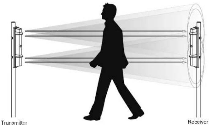
FEATURES
- Quad high power beams
• Double modulated beam - Smart design
- Slim body design
- Easy-to-see vivid interior color for optical alignment
- IP65 ^*1 waterproof structure
• 4 channel beam frequency selector - Alignment level indicator
• Viewfinder with 2X magnification - Various options (refer to page 20) (HU-3*1, ABC-4*1, BC-4*1, CBR-4, PSC-4*1, BAU-4*1)
- UL/c-UL Listed
*1 not evaluated by UL
*2 not require any additional tool
- Beam interruption adjustment function
• D.Q. circuit (environmental disqualification) - Tamper function
- Beam power control selector
- Alarm memory
• Sound assist function - Optical alignment
- Beam reception status
Walk test
[SL-QDM only] - Re-transmitting circuit function
• Solar Battery Unit SBU-4*1 (option)
- Auto Transmit Power Control (A.T.P.C ^8 ) to optimize the beam power
- Integrated Alignment Status Communication (I.A.S.C*2) to communicate the transmitter and receiver
CONTENTS
① INTRODUCTION
1-1 BEFORE YOUR OPERATION 2
1-2 PRECAUTIONS 2
1-3 PARTS IDENTIFICATION....3
② INSTALLATION
2-1 SEPARATING....4
2-2 WIRING....4
2-3 TERMINAL 5
2-4 WIRING DIAGRAM 5
2-5 WIRING DISTANCE BETWEEN POWER SUPPLY AND DETECTOR 6
2-6 WALL MOUNTING 6
2-7 POLE MOUNTING 8
2-8 MOUNTING IN THE BEAM TOWER....9
2-9 INSTALLATION EXAMPLE AT PARTICULAR CASE.. 9
③ FUNCTION SETTING
3-1 DIP SWITCH 10
3-2 BEAM POWER CONTROL SELECTOR..... 10
3-3 FUNCTION....11
④ OPTICAL ALIGNMENT
4-1 OPTICAL ALIGNMENT FOR UPPER AND LOWER BEAM.... 15
5-1 TROUBLESHOOTING 17
⑥ OPTIONAL SETTING
6-1 HEATER UNIT HU-3 (OPTION) 18
6-2 SOLAR BATTERY UNIT SBU-4 (OPTION)... 18
⑦ DIMENSIONS
7-1 DIMENSIONS 19
⑧ SPECIFICATIONS
8-1 SPECIFICATIONS.... 19
⑨ OPTIONS
9-1 OPTIONS 20
1 INTRODUCTION
- Read this instruction manual carefully prior to installation.
• After reading, store this manual carefully in an easily accessible place for reference. - This manual uses the following warning indications for correct use of the product, harm to you or other people and damage to your assets, which are described below. Be sure to understand the description before reading the rest of this manual.
| ⚠Warning | Failure to follow the instructions provided with this indication and improper handling may cause death or serious injury. |
| ⚠Caution | Failure to follow the instructions provided with this indication and improper handling may cause injury and/or property damage. |

This symbol indicates prohibition. The specific prohibited action is provided in and/or around the figure.

This symbol requires an action or gives an instruction.
| Warning | Do not use the product for purposes other than the detection of moving objects such as people and vehicles. Do not use the product to activate a shutter, etc., which may cause an accident. |  |
| Do not touch the unit base or power terminals of the product with a wet hand (do not touch when the product is wet with rain, etc.). It may cause electric shock. | [05KY] | |
| Never attempt to disassemble or repair the product. It may cause fire or damage to the devices. | [SWZ7] | |
| Do not exceed the voltage or current rating specified for any of the terminals during installation, doing so may cause fire or damage to the devices. |  | |
| Caution | Do not pour water over the product with a bucket, hose, etc. The water may enter, which may cause damage to the devices. |  |
| Clean and check the product periodically for safe use. If any problem is found, do not attempt to use the product as it is and have the product repaired by a professional engineer or electrician. |  |
1-2 PRECAUTIONS
Do not install the unit on an unstable surface.
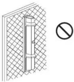
natural_image
Diagram of a vertical structure with a diagonal line and a prohibition symbol (no text or labels)Do not allow the infrared beam from a different model to reach the receiver.
Do not install the pole in a location where sufficient stability can not be ensured.
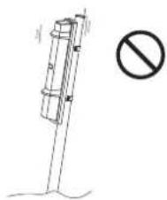
natural_image
Simple line drawing of a pole with a diagonal beam and a prohibition symbol (no text or labels)Install the unit at a height where an object can be detected without fail.
Do not install the unit in a location where trees, leaves, or other objects that may swing in the wind and block the beam.
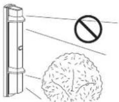
natural_image
Illustration of a fence with a prohibition symbol and a circular object below (no text or labels)The pole size should be 34 - 48mm ( 1.34 - 1.89 inch).
Do not install the receiver in a location where it is exposed to direct sunlight.
![[Receiver]](/content/2026/05/954525/images/ad6eacc8ad9586d71b2681fc8b72f2b3ada7a305686247662e38fae43fc3b2b8.jpg)
Install the unit at least 1 m (3.3 ft.) away from the wall or fence that may be running parallel to the beam.
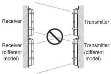
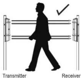
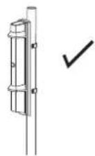
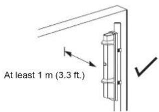

This symbol indicates prohibition.

This symbol indicates recommendation.
For UL/c-UL installations ;
• Reference to UL681, Standard for Installation and Classification of Burglar and Holdup Alarm System.
• Reference to CAN/ULC-S302, ULC Standard for Installation and Classification of Burglar Alarm Systems for Financial and Commercial Premises. Safes and Vaults, & CAN/ULC-S310, ULC Standards for Installation and Classification of Residential Burglar Alarm.
- Conduit is required for all Outdoor Use Application with Conduit Bracket Kit, Model CBR-4, employing appropriate wiring methods.
- Products to be installed within the protected premises.
1-3 PARTS IDENTIFICATION
![Cover Beam blocking plate Main unit Optical lens I.A.S.C lens [QDM only] Horizontal alignment dial Vertical alignment dial Terminals Vertical alignment dial Horizontal alignment dial Optical lens Cover lock screw Viewfinder Main unit base Mounting screw holes Cut bush for wiring Chassis Pole mounting screw holes Wall mounting screw holes Tamper lock plate Tamper button Pole mounting screw holes View finder](/content/2026/05/954525/images/ce0f0ae4504a440dc3d356904905fcd0fb5900affb939940e8007af98ed720ac.jpg)
FUNCTION SETTING SECTION >>
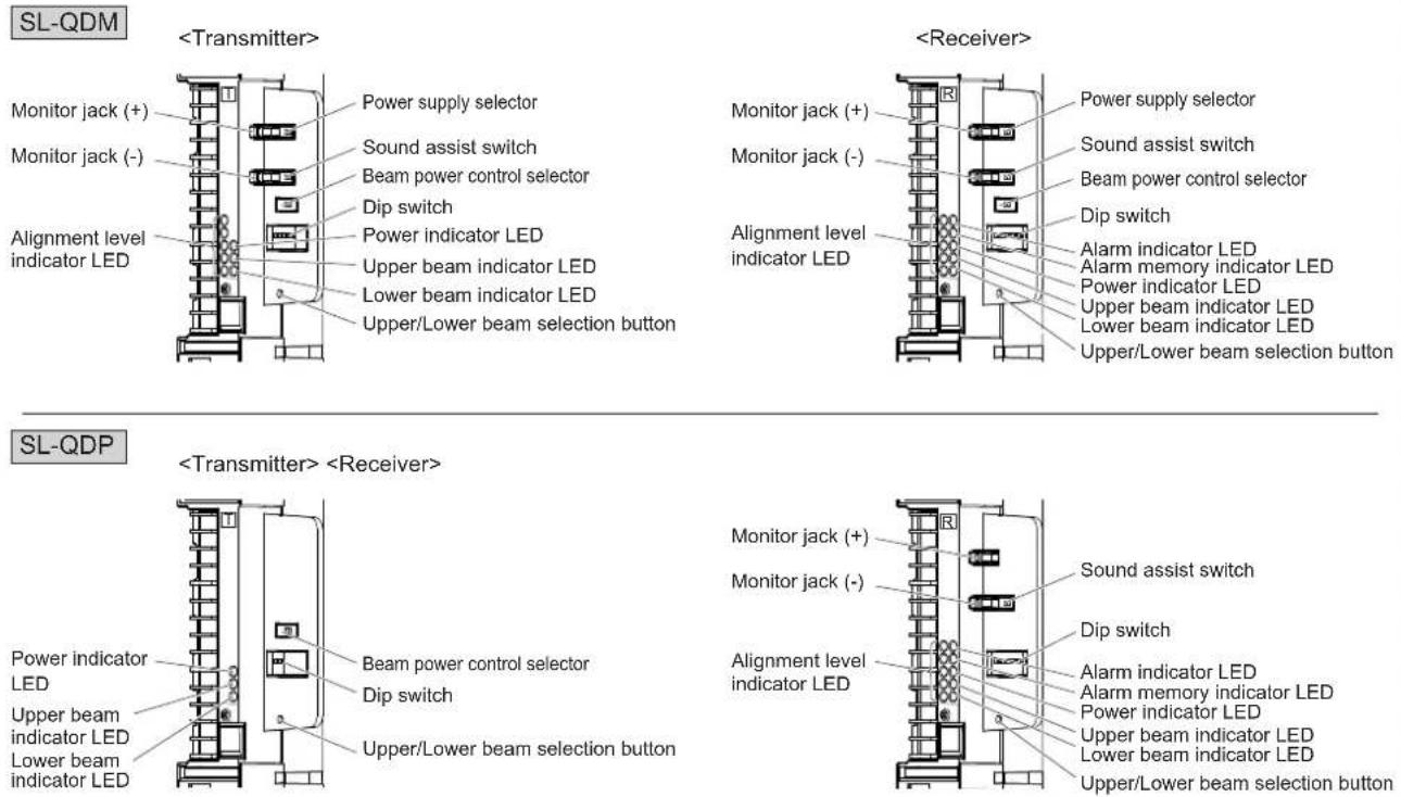
ACCESSORIES >>
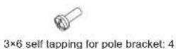
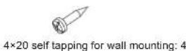
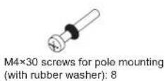
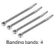
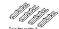
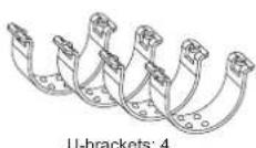

natural_image
Two gray rectangular panels with simple cutouts, no text or symbols presentBeam blocking plate: 2 (attached on the back of the cover)
2 INSTALLATION
2-1 SEPARATING
1 Remove the cover.
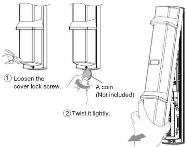
③ Pull
2 Remove the main unit from the chassis.
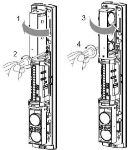
① Turn the optical unit 90 degrees and loosen the screws (both sides).
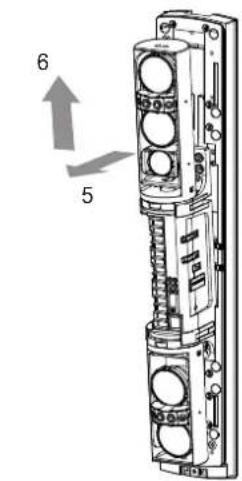
② Pull the upper part of main unit, and raise it to remove.
Caution
Do not place the main unit where it allows to incident direct sunlight to its optical lens during installation. Doing so may cause damage to the product.

2-2 WIRING
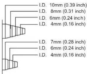
1 Preparing the cut bush
Cut the wiring grommet required according to the wire diameter. Use the lidded grommet for the wiring hole not to be used.
(I.D.: Internal diameter)
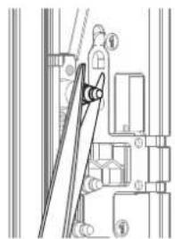
2 Threading the wire
① Cut off the cut bush according to the cable size.
② Pass the cable through the cut bush.
natural_image
Technical line drawing of a mechanical assembly with no visible text or symbols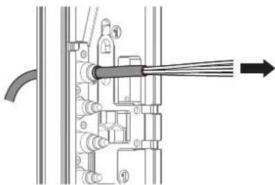
natural_image
Technical diagram of a mechanical assembly with numbered components and an arrow indicating direction (no text or symbols present)③
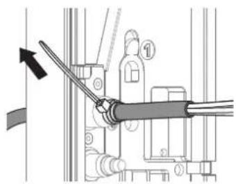
natural_image
Mechanical assembly diagram showing a lever mechanism with no visible text or symbols4
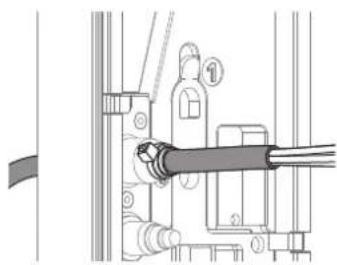
natural_image
Mechanical assembly diagram showing a lever mechanism with no visible text or symbols⑤ Connect to the terminalsCut the excess por
Refer to "TERMINAL" on Page 5 to make connections to the terminals and refer to "OPTICAL ALIGNMENT" on Page 15 to make alignment for the maximum level of light reception.
Caution
Do not exceed the voltage or current rating specified for any of the terminals during installation, doing so may cause fire or damage to the product.

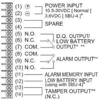
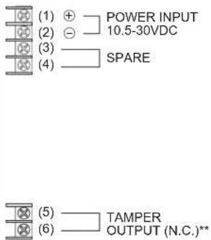
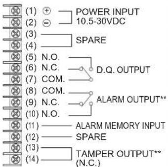
2-3 TERMINAL
| SL-QDM SL-QDP | |||
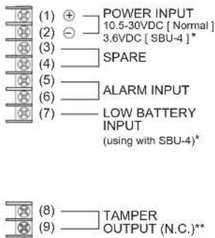 |  |  |  |
Note>>
Connect POWER INPUT ⊖ terminal(2) when wiring LOW BATTERY INPUT* terminal(7) of the transmitter, ALARM MEMORY INPUT terminal(11) and LOW BATTERY INPUT terminal(12) of the receiver.
* SBU-4 and its low battery input/output function not evaluated by UL ** All outputs are power-limited.
2-4 WIRING DIAGRAM
1 1 Set
Connect the power supplies in parallel.
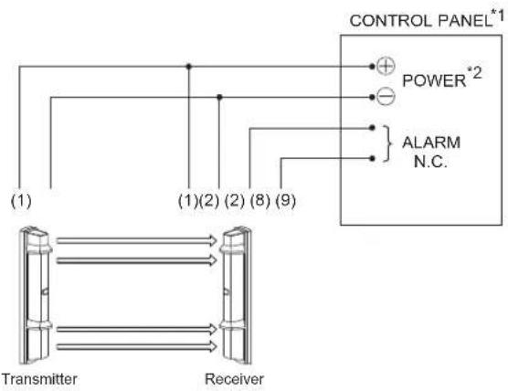
flowchart
graph TD
    A["Transmitter"] --> B["Receiver"]
    C["CONTROL PANEL*1"] --> D["POWER*2"]
    C --> E["ALARM N.C."]
    F["(1)"] --> G["(1)(2) (2) (8) (9)"]
*1 CONTROL PANEL = UL/c-UL listed burglar alarm control panel
*2 POWER = power limited output
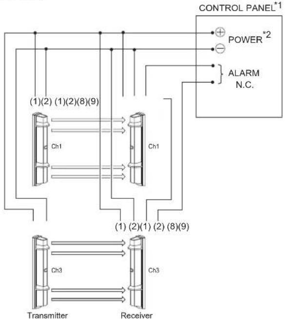
2 2 Sets Stacking
Connect the power supply in parallel. Connect the units serially for a normally closed alarm output and in parallel for a normally open output (the figure below shows an example for a normally closed alarm output).
flowchart
graph TD
    A["Transmitter"] --> B["Receiver"]
    B --> C["Ch1"]
    B --> D["Ch3"]
    C --> E["(1)(2)(1)(2)(8)(9)"]
    D --> F["(1)(2)(1)(2)(8)(9)"]
    G["CONTROL PANEL*1"] --> H["POWER *2"]
    G --> I["ALARM N.C."]
    H --> J["+"]
    I --> K["-"]
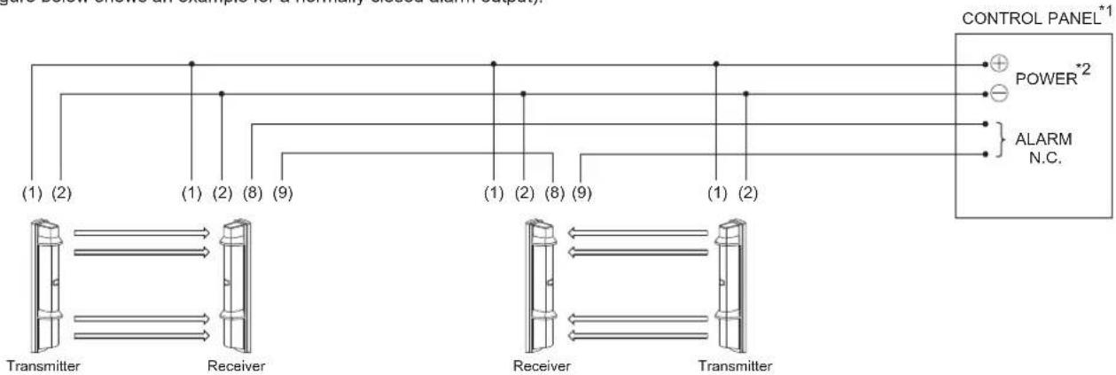
3 2 Sets in the line
Connect the power supply in parallel. Connect the units serially for a normally closed alarm output and in parallel for a normally open output (the figure below shows an example for a normally closed alarm output).
flowchart
graph TD
    A["CONTROL PANEL*1"] --> B["POWER*2"]
    A --> C["ALARM N.C."]
    D["Transmitter"] --> E["Receiver"]
    F["Receiver"] --> G["Transmitter"]
    style A fill:#f9f,stroke:#333
    style B fill:#ccf,stroke:#333
    style C fill:#ccf,stroke:#333
    style D fill:#cfc,stroke:#333
    style E fill:#fcc,stroke:#333
    style F fill:#fcc,stroke:#333
    style G fill:#fcc,stroke:#333
2-5 WIRING DISTANCE BETWEEN POWER SUPPLY AND DETECTOR
- Ensure that the wiring distance from the power supply is within the range shown in the table below.
- When using two or more units on one wire, the maximum length is obtained by dividing the wire length listed below by the number of units used.
| MODEL | SL-200QDM / SL-350QDM / SL-650QDMSL-200QDP / SL-350QDP / SL-650QDP | |
| WIRE SIZE | 12 VDC 24 VDC | |
| 0.33 mm^2 (AWG22) | 600 m(2,000 ft.) | 2,100 m(7,000 ft.) |
| 0.52 mm^2 (AWG20) | 900 m(3,000 ft.) | 3,300 m(10,000 ft.) |
| 0.83 mm^2 (AWG18) | 1,500 m(4,900 ft.) | 5,300 m(17,000 ft.) |
| 1.31 mm^2 (AWG16) | 2,500 m(8,000 ft.) | 8,300 m(27,000 ft.) |
Note>>
UL/c-UL requires to be connected to a UL/c-UL Listed burglar alarm power limited power supply of providing a nominal input of 12 VDC (10.5 to 30 VDC) 30 mA (SL-200/350/650 QDM) or 22 mA (SL-200/350/650 QDP), and battery standby time of 4 hours.
Wiring method shall be in accordance with the National Electrical Code (ANSI / NFPA 70), Canadian Electrical Code, Part 1 (CSA C22.1) Safety Standard for Electrical Installations, local codes, and the authorities having jurisdiction.
2-6 WALL MOUNTING
1 Open the wiring guide on the back of the chassis using pliers as shown.
![[ Upper ] [ Lower ]](/content/2026/05/954525/images/25d84df173961f99542e13469af718c541b32e3475bd7990029964975ca42ef9.jpg)
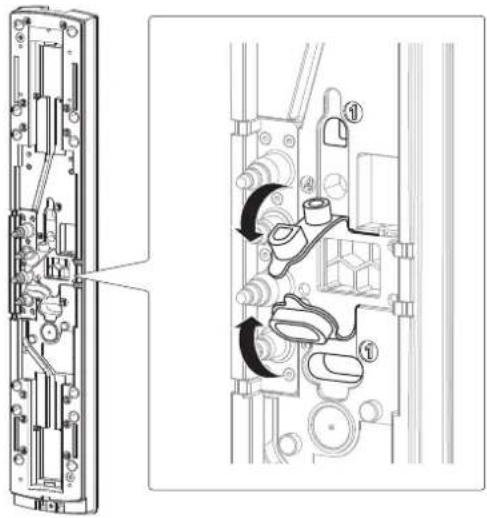
2 Pull the waterproof packing (x2) marked as "①" at the center of the chassis.
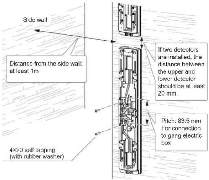
3 Mount the chassis to the wall.
4 Put the waterproof packing back in place.
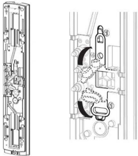
natural_image
Technical line drawing of a mechanical assembly with exploded and assembled views (no text or symbols)Note>>
Install the unit vertically at a height where an object can be detected without fail. In case to be stacked, be careful to cover the detection area totally.
4 Fix the main unit.
① Insert the lower part, and then push the upper part onto the chassis.
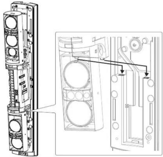
natural_image
Technical line drawing of a mechanical assembly with exploded view and detail view (no text or symbols)② Turn the optical unit 90 degrees and tighten the screws (both sides).
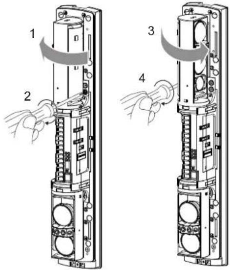

Make function settings and optical alignment before mounting the cover.
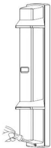
5 Mount the cover and check the operation.
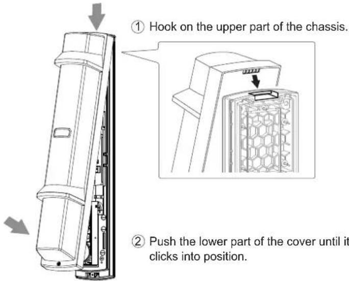
natural_image
Line drawing of a vertical cabinet with a handle and cable attachment (no text or symbols)③ Fasten the cover lock screw.
Note>>
Place the tamper lock plate with the face up. Not doing so may cause damage to the product.


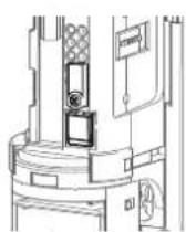
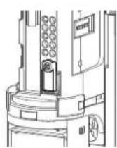
Note>>
Push the middle part of the cover and hide this orange label completely when in operation.
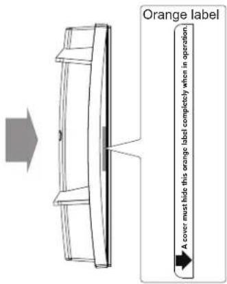

Caution
Do not contact with the optical unit when mounting the cover. Otherwise malfunction may occur due to the shift of the optical axis, resulting in the need of readjustment.

2-7 POLE MOUNTING
1 Using a screwdriver or similar tool, break the knockout position (x4) in the chassis as shown.
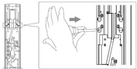
Note>>
- When mounting the single set of detectors to the pole, use a pair of the inside knockouts.
The knockout positions are marked "②" as shown.
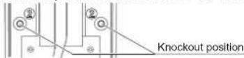
- Break the knockout from the direction shown (inside the chassis). Breaking from the opposite direction (outside of the chassis), makes a risk of generating burrs scratch the wire.
Caution
If you accidentally open an unnecessary knockout, be sure to fill the knockout with rain tight composite like silicone rubber. Not doing so may result in waterproof failure and malfunction of the product.

2 Fix the chassis on the pole.
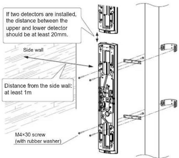
Note>>
- Before fixing the chassis on the pole, temporarily fix one point at the center of the pole mounting bracket to the back of the chassis.
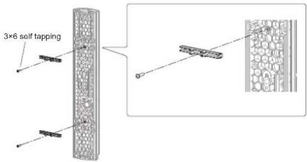
• Install the unit vertically at a height where an object can be detected without fail. In case to be stacked, be careful to cover the detection area totally.
3 Perform the wall mounting procedure of 4 to 5 on page 7.

Make function settings and optical alignment before mounting the cover.
< Installing two detectors in opposing directions >
1 Using a screwdriver or similar tool, break the knockout position (x4) in the chassis as shown.
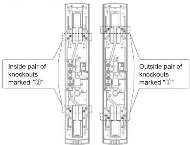
Note>>
- Choose a different pair of knockouts. Pairs of the knockout positions are marked "②" and "③".
2 Fix the chassis on the pole.
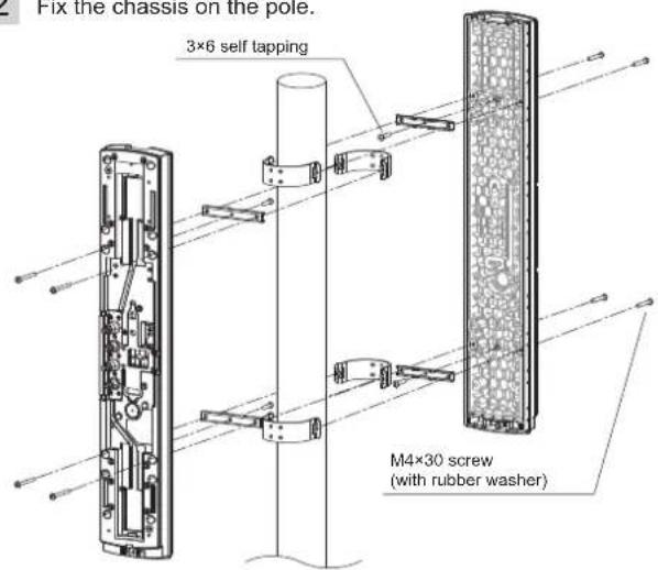
Note>>
- Before fixing the chassis on the pole, temporarily fix one point at the center of the pole mounting bracket to the back of the chassis. Refer to procedure 2 of "Installing one detector".
3 Perform the wall mounting procedure of 4 to 5 on page 7.

Make function settings and optical alignment before mounting the cover.
2-8 MOUNTING IN THE BEAM TOWER
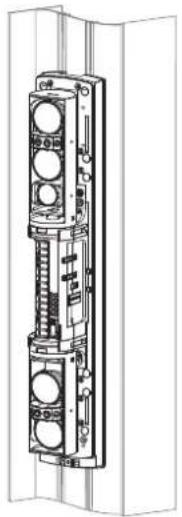
In accordance with the type of the main unit inside the beam tower, install the detector in the same way as wall mounting or pole mounting.
< Mounting with the chassis > < Mounting without the chassis >
natural_image
Technical line drawing of a vertical mechanical or electrical component with multiple circular components mounted on a rectangular base (no text or symbols visible)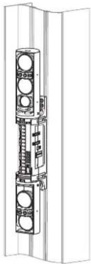
natural_image
Technical line drawing of a vertical mechanical or electrical component with circular components and mounting brackets (no text or symbols)
Make function settings and optical alignment before mounting the cover.
2 When installing the detector without the cover, hold the tamper button with the tamper lock plate on both the transmitter and receiver.
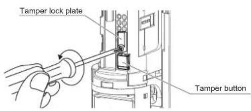
① Loosen the screw.
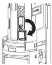
② Rotate the tamper lock plate.
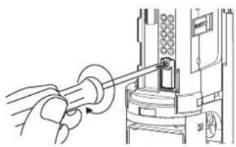
natural_image
Illustration of a hand using a tool to adjust or install a mechanical component (no text or symbols visible)③ Fasten the screw to lock the tamper button.
 | The switch selection is not recognized when locking the tamper button. Release the tamper button before selecting a function using the switch. | ! |
| After completing the settings, be sure to lock the tamper button to check that all LEDs are OFF. If the tamper button is not locked, the LEDs are kept ON, which consumes more battery power. | ! | |
| Monitor jack output become disabled when locking the tamper button. | ! | |
| If you do not close the tamper lock plate, the sensitivity will be reduced as adjustment mode will not end. Be sure to close the tamper with the tamper lock plate. | ! |
2-9 INSTALLATION EXAMPLE AT PARTICULAR CASE
1 If possible, avoid installing the transmitter and receiver facing each other in a slanting direction as shown below.
![[ Top view ]](/content/2026/05/954525/images/0aca8196d080e205707c4b6234364062cf0be17a1114e7cb9685bfe575b5a97c.jpg)
Transmitter Receiver
2 In case you do this installation, the maximum detection range shall be half of the original detection range. (This is to prevent the attenuation of beam by the edge of the cover.)
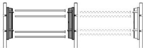
natural_image
Pure diagram of parallel lines passing through a rectangular frame with no text or symbolse.g.) SL-200QDM: 60m/200ft.→ 30m/100ft.
3 FUNCTION SETTING
3-1 DIP SWITCH
| SL-QDM SL-QDP | ||
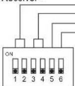
| 4 Channel beam frequency selector switchAlarm input switch [Positive/Negative] | 4 Channel beam frequency selector switch | |
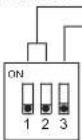 | 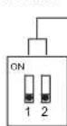 | |
| 4 Channel beam frequency selector switchInterruption time switch [50/100/250/500ms]Alarm memory switch [Auto/Manual]Alarm memory switch [Positive/Negative]D.Q. (environmental disqualification)/Low battery output switch [D.Q./Low battery] | 4 Channel beam frequency selector switchInterruption time switch [50/100/250/500ms]Alarm memory switch [Auto/Manual]Alarm memory switch [Positive/Negative] | |
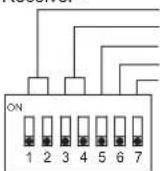 |  | |
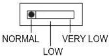
3-2 BEAM POWER CONTROL SELECTOR

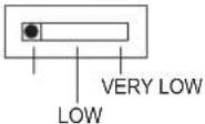
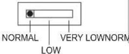
The beam power control selector can be used to avoid unwanted crosstalk that can occur when using multiple photo beams for long distance or beam stacking applications.
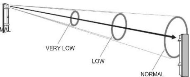
The selector allows you to manually adjust beam power from NORMAL to LOW or VERY LOW.
Make sure the selector select to reduce beam power when using the detector for a distance shorter than the rated distance.
This function is also effective for the following purpose.
- For countermeasure against crosstalk due to reflection of walls or ground.
- For making optical alignment to support peak adjustment when the monitor jack output beams saturated.
Transmitter
Transmitter
< Illustration >
Receiver
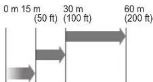
SL-200 QDM/QDP
| NORMAL | 60 - 30 m (200 - 100 ft) |
| LOW | 30 - 15 m (100 - 50 ft) |
| VERY LOW | Within 15 m (Within 50 ft) |
SL-350 QDM/QDP
| NORMAL | 100 - 50 m (350 - 175 ft) |
| LOW | 50 - 25 m (175 - 88 ft) |
| VERY LOW | Within 25 m (Within 88 ft) |
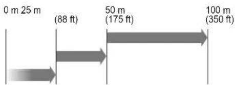
SL-650 QDM/QDP
| NORMAL | 200 - 100 m (650 - 350 ft) |
| LOW | 100 - 50 m (350 - 175 ft) |
| VERY LOW | Within 50 m (Within 175 ft) |

Note>>
Make sure the receiver and transmitter that are facing each other are set to the same position (SL-QDM only).
Caution
Be sure to set the beam power control selector according to the installation distance. Not doing so may result in interference with other sets of detectors.

3-3 FUNCTION
1 4 CHANNEL BEAM FREQUENCY SELECTOR
SL-QDM SL-QDP
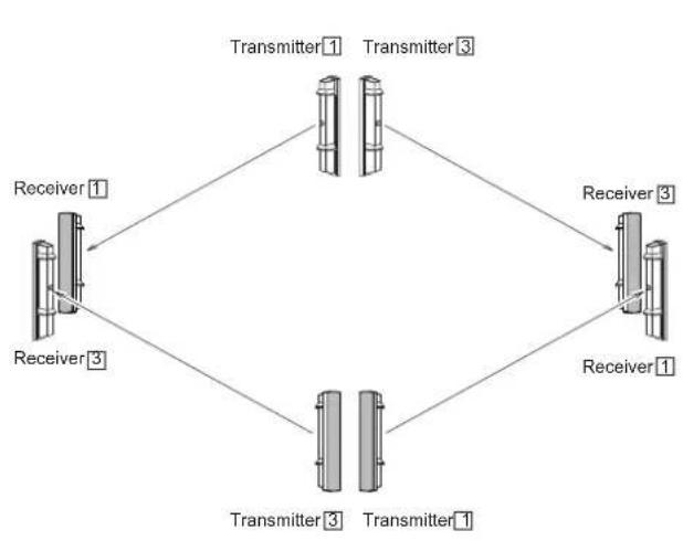
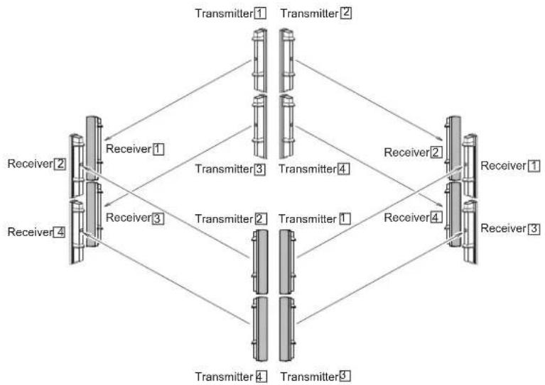
The 4 channel beam frequency selector can be used to avoid unwanted crosstalk that can occur when using multiple photo beams for long distance or beam stacking applications.
• To select between 4 separate beam frequencies, use the switch provided.
- More than double stacked application is not possible.

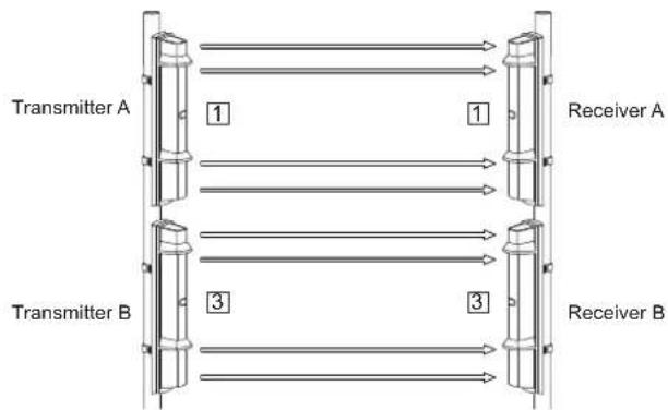
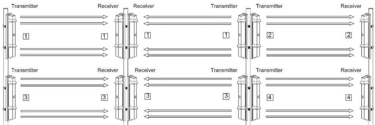
Channel 1 Channel 3Channel 2


Channel 4
a) Double stacked protection
flowchart
graph LR
    subgraph Transmitter_A
        A1["1"] --> B1["Receiver A"]
    end
    subgraph Transmitter_B
        B2["3"] --> C1["Receiver B"]
    end
    A1 --> B1
    B1 --> C1
    C1 --> A2["1"]
    style Transmitter_A fill:#f9f,stroke:#333
    style Transmitter_B fill:#bbf,stroke:#333
    style Receiver_A fill:#dfd,stroke:#333
    style Receiver_B fill:#dfd,stroke:#333
Since Receiver B may receive the infrared beam from Transmitter A, select the frequencies as shown in the figure above. (In the figure, each number in the square indicate a channel numbers.)
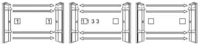
b) Long distance protection
Transmitter A Receiver A Receiver B Transmitter B Transmitter C Receiver C
flowchart
graph TD
    A["1"] --> B["1"]
    B --> C["1"]
    C --> D["3 3"]
    D --> E[" "]
    E --> F[" "]
    F --> G[" "]
    G --> H[" "]
    H --> I[" "]
    I --> J[" "]
    J --> K[" "]
    K --> L[" "]
    L --> M[" "]
    M --> N[" "]
    N --> O[" "]
    O --> P[" "]
    P --> Q[" "]
    Q --> R[" "]
    R --> S[" "]
Since Receiver C may receive the infrared beam from Transmitter A, select their frequencies as shown in the figure above.
c) Double stacked long distance protection
flowchart
graph LR
    subgraph Stage 1
        A1["Transmitter"] --> B1["Receiver"]
        B1 --> C1["Transmitter"]
        C1 --> D1["Receiver"]
    end
    subgraph Stage 2
        A2["Transmitter"] --> B2["Receiver"]
        B2 --> C2["Transmitter"]
        C2 --> D2["Receiver"]
    end
    subgraph Stage 3
        A3["Transmitter"] --> B3["Receiver"]
        B3 --> C3["Transmitter"]
        C3 --> D3["Receiver"]
    end
    subgraph Stage 4
        A4["Transmitter"] --> B4["Receiver"]
        B4 --> C4["Transmitter"]
        C4 --> D4["Receiver"]
    end
Note>>
- More than double stacked application is not possible.
- Make sure the receiver and transmitter that are facing each other are set to the same channel.
Caution
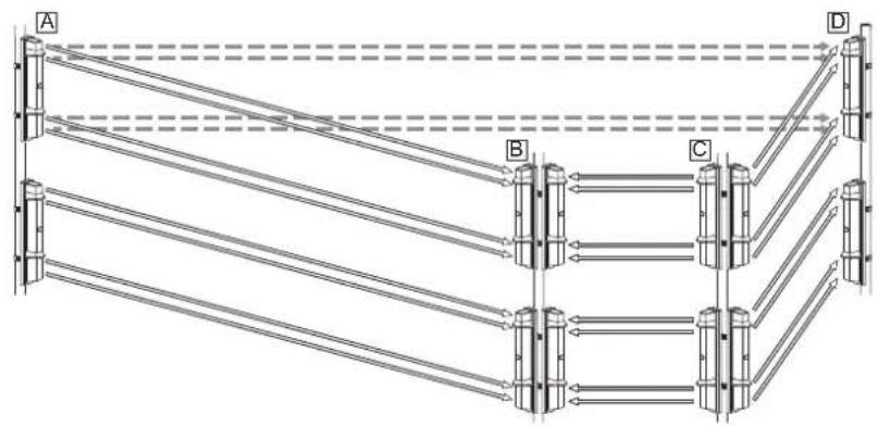
If interference occurs as shown below, use the beam power control selector to reduce beam [A] to less than the specified distance.
natural_image
Pure structural diagram of a truss structure with labeled points A, B, C, D and directional arrows indicating forces or connections (no text or symbols beyond labels)- Lower the beam power control selector of transmitter A by one level. (Refer to 3-2 on page 10.)
- Check that the light receiving level of receiver B is Good or better without blocking light for both upper and lower units.
flowchart
graph TD
    A["Transmitter 1"] --> B["Receiver 1"]
    C["Transmitter 3"] --> D["Receiver 3"]
    E["Transmitter 3"] --> F["Receiver 1"]
    G["Transmitter 3"] --> H["Receiver 1"]
    I["Transmitter 3"] --> J["Receiver 3"]
    B --> D
    D --> F
    F --> H
    H --> J
flowchart
graph TD
    subgraph Receiver_1
        A["Receiver 2"] --> B["Receiver 1"]
        C["Receiver 4"] --> D["Receiver 3"]
        E["Receiver 3"] --> F["Receiver 2"]
        G["Receiver 4"] --> H["Receiver 1"]
    end
    subgraph Receiver_2
        I["Receiver 2"] --> J["Receiver 1"]
        K["Receiver 4"] --> L["Receiver 3"]
        M["Receiver 3"] --> N["Receiver 2"]
        O["Receiver 4"] --> P["Receiver 1"]
        Q["Receiver 3"] --> R["Receiver 4"]
    end
    subgraph Receiver_3
        S["Receiver 2"] --> T["Receiver 1"]
        U["Receiver 4"] --> V["Receiver 3"]
        W["Receiver 3"] --> X["Receiver 2"]
        Y["Receiver 4"] --> Z["Receiver 1"]
        AA["Receiver 3"] --> AB["Receiver 4"]
    end
    subgraph Receiver_4
        AC["Receiver 2"] --> AD["Receiver 1"]
        AE["Receiver 4"] --> AF["Receiver 3"]
        AG["Receiver 3"] --> AH["Receiver 2"]
        AI["Receiver 4"] --> AJ["Receiver 1"]
        AK["Receiver 3"] --> AL["Receiver 4"]
    end
    subgraph Transmitter_1
        AM["Transmitter 1"] --> AN["Transmitter 2"]
        AO["Transmitter 2"] --> AP["Transmitter 3"]
        AQ["Transmitter 3"] --> AR["Transmitter 4"]
        AS["Transmitter 4"] --> AT["Transmitter 1"]
        AU["Transmitter 4"] --> AV["Transmitter 9"]
    end
    subgraph Transmitter_2
        AW["Transmitter 2"] --> AX["Transmitter 3"]
        AY["Transmitter 3"] --> AZ["Transmitter 4"]
        BA["Transmitter 4"] --> BB["Transmitter 1"]
        BC["Transmitter 4"] --> BD["Transmitter 9"]
    end
    subgraph Transmitter_3
        BE["Transmitter 3"] --> BF["Transmitter 4"]
        BG["Transmitter 4"] --> BH["Transmitter 1"]
        BI["Transmitter 4"] --> BJ["Transmitter 9"]
    end
    subgraph Transmitter_4
        BK["Transmitter 4"] --> BL["Transmitter 1"]
        BM["Transmitter 4"] --> BN["Transmitter 9"]
    end
⚠ Warning
Do not attempt to install this product with any other photoelectric detector. It may cause the detector to fail or not respond to movements.

2 BEAM INTERRUPTION ADJUSTMENT

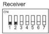
Initial setting is at 50 msec for normal work. According to the speed of a supposed target you select one specific setting out of 4 steps. Set the beam interruption adjustment switches of the receiver according to the speed of the human object to detect.
| Dip switch (Receiver) | ON1 2 3 4 5 6 7 | ON1 2 3 4 5 6 7 | ON1 2 3 4 5 6 7 | ON1 2 3 4 5 6 7 |
| Typical interruption time setting | Running Jogging Walking Slow movement (50 msec) (100 msec) (250 msec) (500 msec)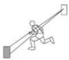 | 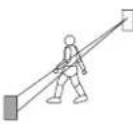 | 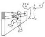 | |
Note>>
The detector operates at 100 msec regardless of the switch position during optical alignment.
3 RE-TRANSMISSION FUNCTION

By connecting a alarm output of other detector to the transmitter. While the alarm input terminal (5) (6) of the transmitter receive the signal from other detectors, the beam is forced to stop and the receiver sends the alarm signal to the control panel.
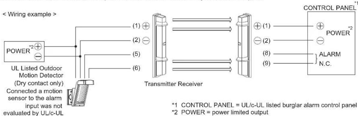
< Dip switch >
Transmitter
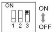
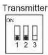
Dip switch 3: Alarm input
| POSITION MODE | |
| ON | Positive (N.C.) |
| OFF | Negative (N.O.) |
Note>>
Switches Positive/Negative according to the connected device.
4 D.Q. (environmental disqualification) /LOW BATTERY OUTPUT
1 The difference between SL-QDM and SL-QDP is as follows.
SL-QDM series: Available to switch between D.Q. output and Low battery output. SL-QDP series: Only set D.Q. output.
< Dip switch >
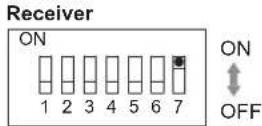
Dip switch 7: D.Q./Low battery
| POSITION FUNCTION MODE | ||
| ON | LOW BATTERY (for Solar Battery Unit SBU-4*) | Refer to 2 below. |
| OFF | D.Q. (environmental disqualification) | Refer to 3 below. |
2 LOW BATTERY mode is used only when SBU-4 is connected. It allows to monitor low battery status of SBU-4\* installed to both the transmitter and receiver at receiver.
< Function >
- The low battery signal from SBU-4* that has been input to the transmitter's LOW BATTERY INPUT terminal (7) is transmitted to the receiver and output from the Low battery output terminals (5) to (7).
- When monitoring low battery status of SBU-4* installed to both the transmitter and receiver at receiver, low battery status cannot be distinguished between the receiver and transmitter. To distinguish a low battery signal of the receiver and transmitter, output the low battery signal directly from SBU-4*.
- When the Power indicator LED of the detector is blinking, SBU-4* is in low battery status so that it can be distinguished which one is in low battery status.
* SBU-4 and its low battery input/output are not evaluated by UL.
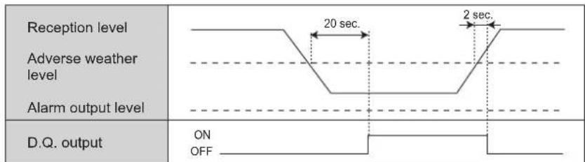
3 The description of D.Q. (environmental disqualification) output is shown below.\*\*
< Function >
D.Q. will send a trouble signal when the beam strength is below acceptable levels, for more than 20 seconds, due to rain, snow, or heavy fog.
** D.Q. output was not evaluated by UL/c-UL
< Wiring example >
A. Trouble Output + Alarm Output
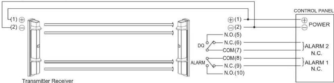
flowchart
graph LR
    A["Transmitter Receiver"] --> B["Control Panel"]
    B --> C["POWER"]
    A --> D["ALARM 1 N.C."]
    A --> E["ALARM 2 N.C."]
    A --> F["COM(8)"]
    A --> G["COM(7)"]
    A --> H["N.C.(6)"]
    A --> I["N.O.(5)"]
    A --> J["⊕(1)"]
    A --> K["⊖(2)"]
    A --> L["⊕(1)"]
    A --> M["⊖(2)"]
    A --> N["⊕(1)"]
    A --> O["⊖(2)"]
    style A fill:#f9f,stroke:#333
    style B fill:#ccf,stroke:#333
    style C fill:#cfc,stroke:#333
    style D fill:#fcc,stroke:#333
    style E fill:#cff,stroke:#333
    style F fill:#ffc,stroke:#333
    style G fill:#fcc,stroke:#333
    style H fill:#cff,stroke:#333
    style I fill:#fcc,stroke:#333
    style J fill:#cff,stroke:#333
    style K fill:#fcc,stroke:#333
    style L fill:#cff,stroke:#333
    style M fill:#fcc,stroke:#333
B. Bypasses Alarm
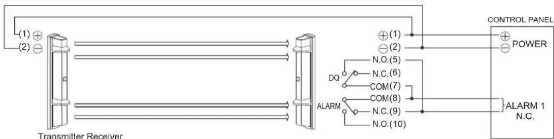
C. Bypasses Alarm + Trouble Output
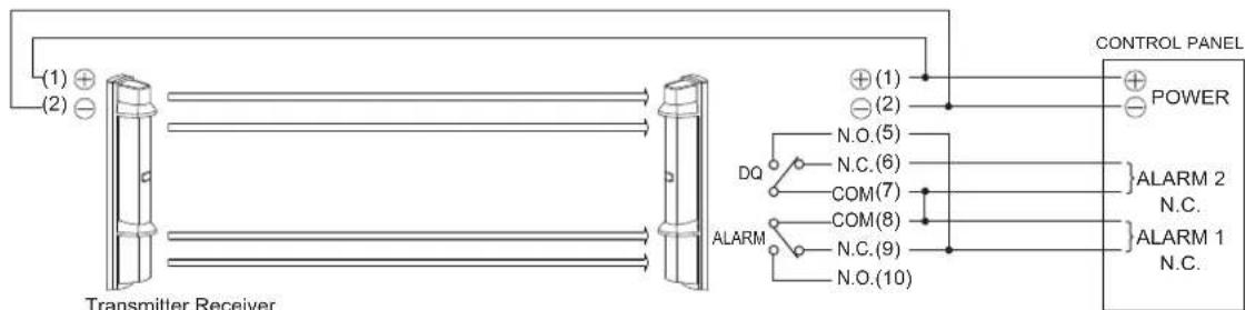
flowchart
graph TD
    A["Transmitter Receiver"] --> B["Switch 1"]
    A --> C["Switch 2"]
    A --> D["Switch 3"]
    A --> E["Switch 4"]
    A --> F["Switch 5"]
    A --> G["Switch 6"]
    A --> H["Switch 7"]
    A --> I["Switch 8"]
    A --> J["Switch 9"]
    A --> K["Switch 10"]
    L["ALARM"] --> M["DQ"]
    L --> N["N.O.(5)"]
    L --> O["N.C.(6)"]
    L --> P["COM(7)"]
    L --> Q["COM(8)"]
    L --> R["ALARM"]
    L --> S["N.C.(9)"]
    L --> T["N.O.(10)"]
    U["CONTROL PANEL"] --> V["POWER"]
    W["ALARM 2 N.C."] --> X
    Y["ALARM 1 N.C."] --> Z
Note>>
If the control panel's input terminals have the same common, the alarm output, sleep and trouble output can be triggered simultaneously.
5 ALARM MEMORY FUNCTION
When an alarm is activated during alert status, the detector memorizes the alarm activation.
This will allow you to check which detector activated an alarm even when multiple units are installed.
In Remote mode, connect control voltage signal terminal (system arming status voltage output terminal) of control panel to ALARM MEMORY INPUT terminal (11).
< Wiring example >
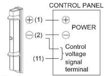
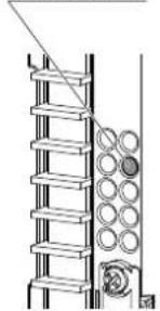
Receiver
Alarm memory indicator LED
natural_image
Technical line drawing of a mechanical assembly with spring and circular components (no text or symbols)< Dip switch >
Receiver
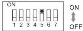
| FUNCTIONMODEPOSITION | ||
| ON | AUTO(Timer mode) | < Operating time chart >Alarm outputAlarm memory indicatorON OFF5 min. 55 min.5 min. 55 min.The alarm memory indicator is illuminated after approximately 5 minutes since the last alarm generated, and kept illuminated for approximately 55 minutes.The duration of illumination will not be extended even if an alarm generated while the alarm memory indicator is illuminated. Approximately 55 minutes later, the indicator will be automatically reset and returned to normal mode. |
| OFF | MANUAL(Remote mode) | < Operating time chart >Alarm outputAlarm systemArmed DisarmedAlarm memory indicatorON OFFWhen an alarm generated, the detector retains it in the memory.When switching the security system from "System armed" to "System disarmed"(switching the position), the alarm memory indicator of the detector that memorizes the alarm memory indicator will be illuminated.When putting the security system back on (switching the position), the alarm memory indicator will be turned off and reset.Once the reset is made, the alarm memory indicator will not be illuminated even if the security system is switched to "System disarmed" until an alarm outputs again.< Dip switch 6: Alarm memory [Positive/Negative] >ReceiverON1 2 3 4 5 6 7Selective OutputReceiverON1 2 3 4 5 6 7Positive (N.C.) System armed: OPEN or + 5~30VDC System disarmed: 0~1VDC (grounded)Negative (N.O.) System armed: 0~1VDC (grounded) System disarmed: OPEN or + 5~30VDC |
6 SOUND ASSIST FUNCTION
This function informs you of the operation and condition by sounds.
It works well on the two situations below:
< Optical alignment >
The optical alignment level can be checked with sound. The stronger the sensitivity, the faster the sound pattern. It sounds when the alignment level indicators are illuminated, the tamper button is not pressed.
< Walk test >
Operation check can be performed by the beep sound at interruption for 5 minutes after the tamper button on both the transmitter and receiver are pressed (after the cover is closed). The sound assist function automatically finishes after 5 minutes.
![Sound assist [ON/OFF]](/content/2026/05/954525/images/aa7d6321bf99d8fa2aeb55cc8ab0da3fc569ff3f351dc9f727632f819c4a4db0.jpg)
| Walk testOptical alignment | |||
| SOUNDING DETECTOR | SL-QDM: Receiver and transmitter SL-QDP: Receiver | Receiver | |
| POSITION | ON | ||
| OFF OFF OFF | |||
4 OPTICAL ALIGNMENT
4-1 OPTICAL ALIGNMENT FOR UPPER AND LOWER BEAM
Optical alignment is an important adjustment to increase reliability. Be sure to take adjustment steps 1 through 6 described below to attain the maximum level of the output through the monitor jack.
< Horizontal alignment angle > < Vertical alignment angle > [ TOP VIEW ] [ SIDE VIEW ]
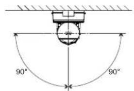
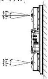
1 See "3-2" on page 10 and set the 4 channel beam frequency selector.
2 Block lower beam by the beam blocking plate or Upper/Lower beam selection button.
< Using a beam blocking plate >
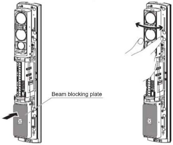
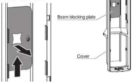
Note>>
- Mount a beam blocking plate to the lower unit and then start optical alignment from the upper unit.
- Beam blocking plate is attached on the back of the cover.
- Put back the beam blocking plate to the cover after use.
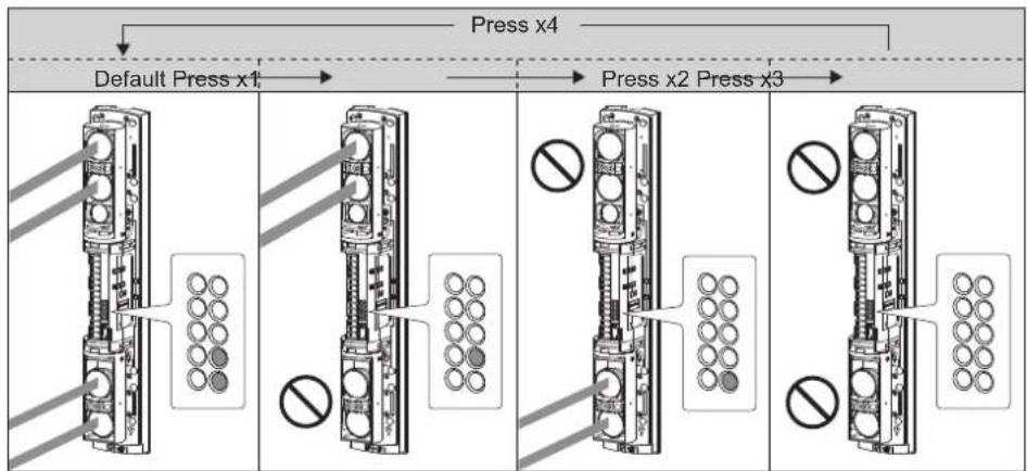
< Using Upper/Lower beam selection button >
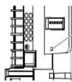
Note>>
• Make the same settings on both the transmitter and receiver for the same LED indication patterns.
• The selection button of the transmitter and receiver are not linked.
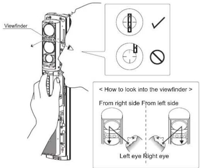
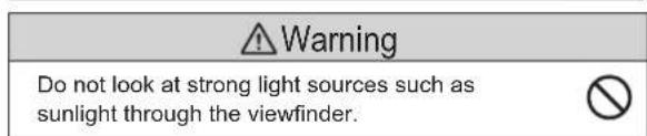
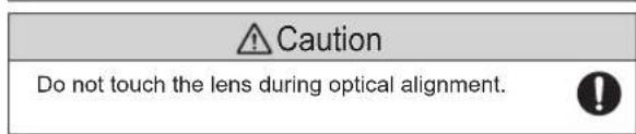
3 Look into the viewfinder and perform fine alignment of the horizontal and vertical angles using the alignment dial.
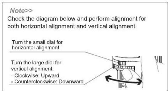
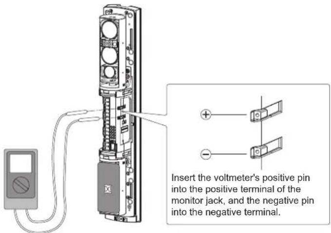
4 After the alignment using the viewfinder, make adjustment with the voltmeter for more accurate optical alignment.
Set the voltmeter range to 5 to 10 VDC.
After checking the receiving level of optical axis by using the alarm indicator, make sure to make fine alignment for both the transmitter and receiver with voltmeter to achieve a monitor output level of "Excellent".
5 Adjust the horizontal and vertical angle while checking the light receiving status by the alignment level indicator LEDs and sound.
NOTE>>
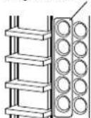
The alignment level indicators have 5 LEDs, each LED represents the level of alignment, ranging from poor to excellent. Each LED will indicate 3 steps of alignment, slow blink = okay, fast blink = better, continuously on = best, providing 15 graduated stages.
The optical alignment level can also be checked by sound.
(SL-QDP: Receiver only)
See the following table for operations of LED display and sound.
Alignment level indicator LED

OFF Slow blink Fast blink Continuously ON
SL-QDM series: Optical alignment can be performed by opening a cover of either the transmitter or receiver.
6 Make the settings of 1 to 5 to the lower as well.
| Caution | Press the tamper buttons on both the receiver and transmitter (close the covers) after performing optical alignment for a set of detectors.Not doing so may result in interference with other sets of detectors and posing a problem on optical alignment. |
4-2 OPERATION CHECK
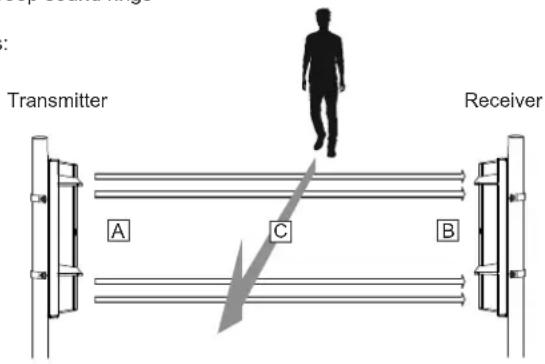
Conduct a walk to check that the alarm indicator LED on the receiver turns ON or the beep sound rings on the receiver as the walker interrupts the beam.
Be sure to conduct a walk test (to block the infrared beam) at the following three points:
A In front of the transmitter
B In front of the receiver
C At the middle point between the transmitter and the receiver
The detector is installed properly when the Alarm indicator LED turns ON and the beep sound rings in the tests at all three points.
Note>>
- Conduct a walk test at least once a year.
- Operation check can be performed by the beep sound at interruption for 5 minutes of the tamper button on both the transmitter and receiver are pressed (the covers are closed).
5 TROUBLESHOOTING
5-1 TROUBLESHOOTING
| PROBLEM POSSIBLE CAUSE CORRECTIVE ACTION | ||
| LEDs are not illuminated(Transmitter/receiver) | Inappropriate power voltage | Check the voltage and make sure that it is between 10.5 and 30 VDC |
| Inappropriate wiring distance or wire diameter | See "2-5 WIRING DISTANCE BETWEEN POWER SUPPLY AND DETECTOR" on page 6,check the wiring distance. | |
| Power supply selector setting is incorrect. | See "6-2 SOLAR BATTERY UNIT SBU-4 (OPTION)" on page 18, check the power supply selector setting: Normal (left), SBU-4 (right) | |
| "ALARM" LED is not illuminated even if the beam is blocked | Reflection of the floor or wall. | See"4-1 OPTICAL ALIGNMENT" on Page 15 and make realignment. If the problem persist, see "BEAM POWER CONTROL SELECTOR" on Page 13 and step down the beam power. |
| Beam has not been blocked. | Block all four beams at same time | |
| Blocking the beam, and illuminates "ALARM" LED but does not active the alarm. | Signal line short-circuited | Check the wiring. |
| Alarm contact welded | Repair is required. Contact the distributor or us. | |
| Alignment level indicator LEDs are not illuminated (Transmitter/Receiver) | Optical alignment is not optimized. | See "4-1 OPTICAL ALIGNMENT" on Page 15 and make realignment. |
| The channel setting between the Transmitter and the Receiver does not match. | See "3-3 1 4 CHANNEL BEAM FREQUENCY SELECTOR" on Page 11 and set to the same channel. | |
| Alignment level indicator LEDs of only the Transmitter are not illuminated. | Inappropriate optical alignment for the upper beam unit. | See"4-1 OPTICAL ALIGNMENT" on Page 15 and make realignment. |
| Alarm is activated even if the beam is not blocked | Interruption time is too short | See "BEAM INTERRUPTION ADJUSTMENT" on page 11, set an appropriate interruption time. |
| Surface of the transmitter/receiver cover soiled | Clean the cover (wipe the cover with a soft cloth dampened with water-diluted neutral detergent) | |
| Channels of the transmitter and receiver are different | Set the same channel to both the transmitter and receiver. | |
| Multiple photoelectric detector for long distance or beam stacking applications. | Set channels 1-3 or 2-4 or 1-4. | |
| Optical alignment was not performed properly | See"4-1 OPTICAL ALIGNMENT" on Page 15 and make realignment. | |
| Frost, snow or heavy rain causes false alarm. | Optical alignment is not optimized | See"4-1 OPTICAL ALIGNMENT" on Page 15 and make realignment. |
| Improper output | The wiring is incorrect | Make correct wiring. |
6
OPTION SETTING
6-1 HEATER UNIT HU-3 (OPTION) \* not evaluated by UL
The heat release effect makes the unit less prone to frost. HU-3 can be mounted to either upper or lower part of the unit. Use a 24 V power supply to use HU-3.
< Mounting method >
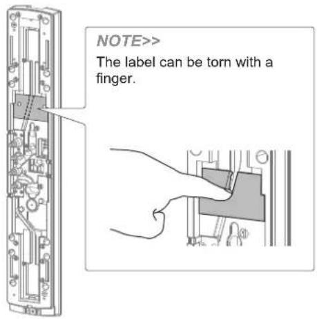
1 Tear the wiring groove section of the label that is pasted on the chassis as shown below.
2 Insert HU-3 into the chassis.
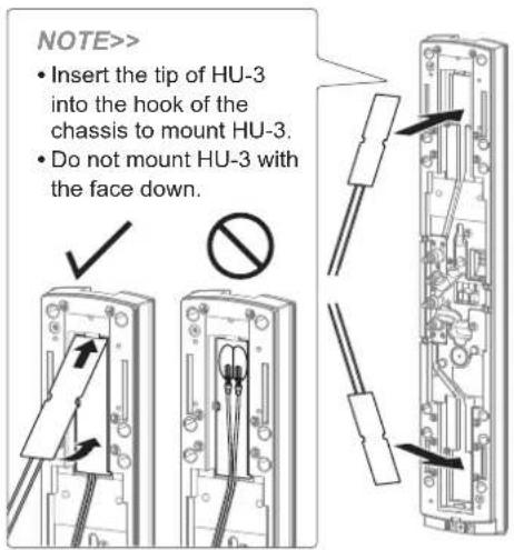
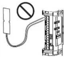
Caution
Do not wire HU-3 to the main unit. Doing so may result in malfunction.
natural_image
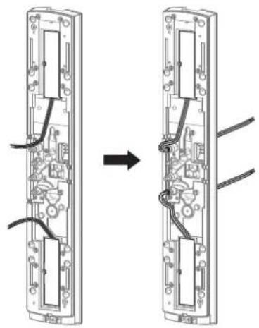
Diagram of a cable with a prohibition symbol and a device connected to its cable (no text or labels present)3 Route the cable along the wiring groove and draw the cable through the cutbush.
natural_image
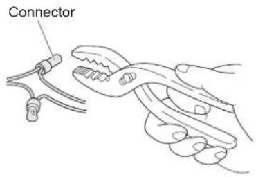
Diagram showing two views of a device with internal components and wiring, no text or symbols present4 When connecting the lead wires to the wiring, make the connection using the included connector or soldering. Insert the wires into the connector and tighten the connections with pliers.
NOTE>>
Ensure that the wiring distance from the power supply is within the range shown in the table on the right. When using 2 or more units on 1 wire, the maximum wiring distance is obtained by dividing the wire distance by the number of unit used.
| Wiring distance from power supply | |
| Wire size | Power supply: 24 VAC/DC |
| 0.83 mm ^2 (AWG18) | 300 m (1000 ft.) |
| 1.31 mm ^2 (AWG16) | 500 m (1700 ft.) |
| 2.09 mm ^2 (AWG14) | 800 m (2600 ft.) |
6-2 SOLAR BATTERY UNIT SBU-4 (OPTION) \* not evaluated by UL
SL-QDM
SL-002
When using the Solar Battery Unit SBU-4 together with SL-QDM, set Power Supply Selector from Normal to SBU-4 position.
![Power Supply Selector [Normal/SBU-4] NORMAL 10.5 - 30 V SOLAR SBU-4 3.6 V](/content/2026/05/954525/images/435e5916cfdd2f88e48b63b4821d2ed537d98e8ff26c39d6da12bf3f12ccbf15.jpg)
Caution
- When using SBU-4 (option), be sure to read the SBU-4 manual.

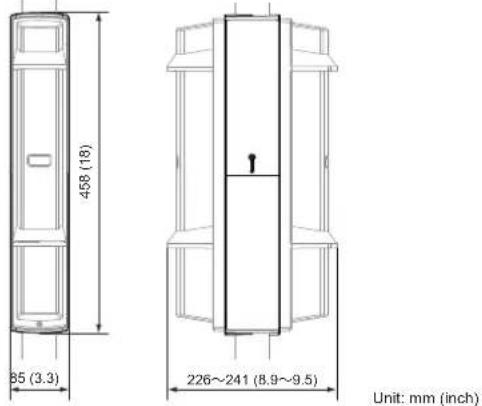
7 DIMENSIONS
7-1 DIMENSIONS
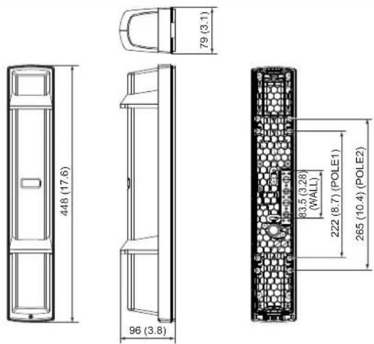
Unit: mm (inch)
8 SPECIFICATIONS
8-1 SPECIFICATIONS
< SL-200QDM, SL-350QDM, SL-650QDM, SL-200QDP, SL-350QDP, SL-650QDP >
| Model | ADVANCED | STANDARD | |||||
| SL-200QDM SL-350QDM SL-650QDM SL-200QDP SL-350QDP SL-650QDP | |||||||
| Maximum detection range | 60 m / 200ft 100 m / 350 ft 200 m / 650 ft 60 m / 200ft | 100 m / 350 ft 200 m / 650 ft | |||||
| Maximum arrival distance*1*2 | 600 m / 2,000ft 1,000 m / 3,500 ft 2,000 m / 6,500 ft 600 m / 2,000ft 1,000 m / 3,500 ft | m / 2,000ft 1,000 m / 3,500 ft | 2,000 m / 6,500 ft | ||||
| Detection method | Quad infrared beam interruption detection | ||||||
| Selectable beam frequency | 4 channels | ||||||
| Interruption time | Variable between 50/100/250/500 ms (4 steps) | ||||||
| Power source*3 | Normal: 10.5 - 30 VDCSolar Battery Unit SBU-4*1 (OPTION): 3.6 VDC | 10.5 - 30 VDC | |||||
| Current draw | Normal | 10.5-30VDC | 26 mA(T: 11 mA, R: 15 mA) | 30 mA(T: 15 mA, R: 15 mA) | 17 mA(T: 6 mA, R: 11 mA) | 22 mA(T: 11 mA, R: 11 mA) | |
| SBU-4*1 | 26 mA(T: 9 mA, R: 17 mA) | 35 mA(T: 18 mA, R: 17 mA) | — | — | |||
| Optical alignment | 10.5-30VDC | 36 mA(T: 16 mA, R: 20 mA) | 43 mA(T: 20 mA, R: 23 mA) | 21 mA(T: 7 mA, R: 14 mA) | 24 mA(T: 10 mA, R: 14 mA) | ||
| SBU-4*1 | 45 mA(T: 17 mA, R: 28 mA) | 60 mA(T: 26 mA, R: 34 mA) | — | — | |||
| Peak | 10.5-30VDC(UL evaluated) | 40 mA(T: 16 mA, R: 24 mA) | 43 mA(T: 20 mA, R: 23 mA) | 24 mA(T: 7 mA, R: 17 mA) | 33 mA(T: 10 mA, R: 23 mA) | ||
| Output*4 | Alarm output | Form C relay: 30 VDC, 0.2 A | |||||
| Alarm period | 2 sec (±1) (Nominal) | ||||||
| D.Q. output1 | Form C relay: 30 VDC, 0.2 A(D.Q. and Low battery can be switched.) | Form C relay: 30 VDC, 0.2 A | |||||
| Low battery output | — | ||||||
| Tamper output | N.C. (contact output): 30 VDC, 0.1 A Opens when the cover removed. | ||||||
| Operating temperature | -35°C - +60°C (-30°F - 140°F) | ||||||
| Operating humidity | 95 % (max.) | ||||||
| Alignment angle | ±90° Horizontal, ±10° Vertical | ||||||
| Dimension | H x W x D mm (inch): 448 (17.6) x 79 (3.1) x 96 (3.8) | ||||||
| Weight | 2500 g (Total weight of the transmitter + receiver, excluding accessories) | 2400 g (Total weight of the transmitter + receiver, excluding accessories) | |||||
| International protection | IP65*1 | ||||||
< HU-3 (Option) >*1
| Model HU-3 | |
| Power input | 24 VAC/DC |
| Current draw | 210 mA max. per 1 piece / 420 mA max. per 1 unit |
| Thermo switch | 60°C (140°F) |
| Operating temperature | -35°C - +60°C (-31°F - +140°F) |
| Weight | 20 g (0.7oz) (Heater (x2)) |
| Packages | Heater (x2), Connector (x4), Waterproof agent |
NOTE
These units are designed to detect an intruder and activate an alarm control panel. Being only a part of a complete system, we cannot accept responsibility for any damages or other consequences resulting from an intrusion. These products conform to the EMC Directive 2004/108/EC.
*1 not evaluated by UL
*2 "Maximum Arrival Distance" shows the optical margin for the detection range.
*3 UL listed power-limited burglar alarm power supply.
*4 All relays are Dry-Contact and all outputs are power-limited.
*5 All interconnecting devices must be UL/c-UL listed.
*6 All inputs and outputs must be connected to power limited circuit only.
9-1 OPTIONS
Anti Bird Cap ABC-4
Prevent birds and small animals from the detector to reduce the false alarm. Prevent streaming rain and snow from the front of the detector to keep the sensitivity.
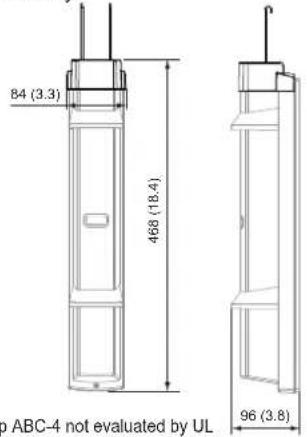
* Anti Bird Cap ABC-4 not evaluated by UL
Unit: mm (inch)
Back Cover BC-4
Conceal the back side of pole mounted detector.

* Back Cover BC-4 not evaluated by UL
Conceal the gap of pole mounted detectors back to back.
* Pole Side Cover PSC-4 not evaluated by UL
Solar Battery Unit SBU-4 (SL-QDM only)
Supply power by using solar battery.
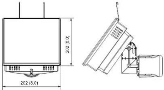
* Solar Battery Unit SBU-4 not evaluated by UL
Unit: mm (inch)
Beam Alignment Unit BAU-4
Adjust optical axis automatically. (SL-QDM: Transmitter/receiver) (SL-QDP: Receiver only)
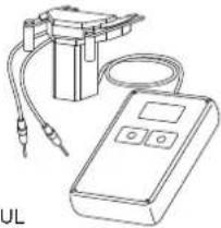
natural_image
Line drawing of a medical or electrical device with tubing and a control panel (no text or symbols)* Beam Alignment Unit BAU-4 not evaluated by UL
Heater Unit HU-3
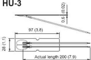
* Heater Unit HU-3 not evaluated by UL
Unit: mm (inch)

OPTEX
OPTEX CO., LTD. (JAPAN)
URL: http://www.optex.net/
OPTEX INC. (U.S.)
URL: http://www.optexamerica.com/
OPTEX DO BRASIL LTDA. (Brazil)
URL: http://www.optex.net/br/es/sec/
OPTEX (EUROPE) LTD. / EMEA HQ (U.K.)
URL: http://www.optexeurope.com/
OPTEX TECHNOLOGIES B.V.
(The Netherlands)
URL: http://www.optex.nl/
OPTEX SECURITY SAS (France)
URL: http://www.optex-security.com/
OPTEX SECURITY Sp.z o.o. (Poland)
URL: http://www.optex.com.pl/
OPTEX PINNACLE INDIA, PVT., LTD. (India)
URL: http://www.optex.net./in/en/sec/
OPTEX KOREA CO.,LTD. (Korea)
URL: http://www.optexkorea.com/
- PHOTOELECTRIC DETECTOR
- Smart Line™ series
- FEATURES
- CONTENTS
- INTRODUCTION
- 1-2 PRECAUTIONS
- For UL/c-UL installations ;
- INSTALLATION
- 2-1 SEPARATING
- Caution
- 2-2 WIRING
- Preparing the cut bush
- Threading the wire
- 2-3 TERMINAL
- 2-4 WIRING DIAGRAM
- 1 Set
- 2 Sets Stacking
- 2 Sets in the line
- 2-5 WIRING DISTANCE BETWEEN POWER SUPPLY AND DETECTOR
- Note>>
- 2-6 WALL MOUNTING
- Fix the main unit.
- Mount the cover and check the operation.
- 2-7 POLE MOUNTING
- 2-8 MOUNTING IN THE BEAM TOWER
- 2-9 INSTALLATION EXAMPLE AT PARTICULAR CASE
- FUNCTION SETTING
- 3-1 DIP SWITCH
- 3-2 BEAM POWER CONTROL SELECTOR
- 3-3 FUNCTION
- 4 CHANNEL BEAM FREQUENCY SELECTOR
- ⚠ Warning
- BEAM INTERRUPTION ADJUSTMENT
- RE-TRANSMISSION FUNCTION
- D.Q. (environmental disqualification) /LOW BATTERY OUTPUT
- The difference between SL-QDM and SL-QDP is as follows.
- LOW BATTERY mode is used only when SBU-4 is connected. It allows to monitor low battery status of SBU-4\* installed to both the transmitter and receiver at receiver.
- The description of D.Q. (environmental disqualification) output is shown below.\*\*
- ALARM MEMORY FUNCTION
- SOUND ASSIST FUNCTION
- OPTICAL ALIGNMENT
- 4-1 OPTICAL ALIGNMENT FOR UPPER AND LOWER BEAM
- 4-2 OPERATION CHECK
- TROUBLESHOOTING
- 5-1 TROUBLESHOOTING
- 6
- OPTION SETTING
- 6-1 HEATER UNIT HU-3 (OPTION) \* not evaluated by UL
- 6-2 SOLAR BATTERY UNIT SBU-4 (OPTION) \* not evaluated by UL
- DIMENSIONS
- 7-1 DIMENSIONS
- SPECIFICATIONS
- 8-1 SPECIFICATIONS
- NOTE
- 9-1 OPTIONS
- Anti Bird Cap ABC-4
- Back Cover BC-4
- Solar Battery Unit SBU-4 (SL-QDM only)
- Beam Alignment Unit BAU-4
- Heater Unit HU-3
- OPTEX
- OPTEX CO., LTD. (JAPAN)
- OPTEX INC. (U.S.)
- OPTEX DO BRASIL LTDA. (Brazil)
- OPTEX (EUROPE) LTD. / EMEA HQ (U.K.)
- OPTEX TECHNOLOGIES B.V.
- (The Netherlands)
- OPTEX SECURITY SAS (France)
- OPTEX SECURITY Sp.z o.o. (Poland)
- OPTEX PINNACLE INDIA, PVT., LTD. (India)
- OPTEX KOREA CO.,LTD. (Korea)
Brand : OPTEX
Model : SL-650QDP-BT
Category : Uncategorized