
EF5000 - Heating Escea - Free user manual and instructions
Find the device manual for free EF5000 Escea in PDF.


| Product Type | Outdoor Gas Fire Heater |
| Brand | Escea |
| Model | EF5000 |
| Dimensions (Width x Height x Depth) | 1000 mm x 579 mm x 320 mm |
| Gas Types | Natural Gas, Propane, ULPG |
| Gas Input (Natural Gas) | 49 MJ/hr |
| Gas Input (Propane / ULPG) | 40 MJ/hr |
| Minimum Inlet Pressure (Natural Gas) | 1.0 kPa |
| Operating Pressure (Natural Gas) | 1.0 kPa |
| Operating Pressure (Propane) | 2.0 kPa |
| Operating Pressure (ULPG) | 2.2 kPa |
| Power Supply | 230/240V AC via supplied transformer, 24V AC 1A output |
| Ignition Type | Electronic spark ignition with pilot flame |
| Control Type | ON/OFF rocker switch on fascia |
| Installation Options | Freestanding, partially enclosed, corner |
| Minimum Ceiling Clearance | 1400 mm above fascia |
| Minimum Clearance in Front | 1000 mm (people, pets, furniture) |
| Minimum Side Clearance to Adjacent Wall | 270 mm from fascia edge |
| Recommended Service Interval | Annually |
| Fascia Material | Stainless steel (powder coated option) |
| Fuel Bed Media | Ceramic stones and river stones (separate compartments) |
| Approval Standard | AS/NZS 5263.1.3:2016 |
| Warranty | Subject to installation by registered installer; void if modified |
Frequently Asked Questions - EF5000 Escea
User questions about EF5000 Escea
0 question about this device. Answer the ones you know or ask your own.
Ask a new question about this device
Download the instructions for your Heating in PDF format for free! Find your manual EF5000 - Escea and take your electronic device back in hand. On this page are published all the documents necessary for the use of your device. EF5000 by Escea.
USER MANUAL EF5000 Escea
Installation / Service Instructions
EF5000
Gas Fireplace
Important:
The appliance shall be installed in accordance with;
• This installation instruction booklet
- Local gas fitting regulations
• Municipal building codes
• Electrical wiring regulations
- Any other relevant statutory regulations
• AS/NZS 5601:2013 Gas Installations

WARNING:
This appliance must be installed by a qualified person.
This manual is ONLY for fires with a serial number from 81000 onwards.
- DO NOT SPRAY AEROSOLS IN THE VICINITY OF THIS APPLIANCE WHILE IT IS IN OPERATION.
• DO NOT USE OR STORE FLAMMABLE MATERIALS IN OR NEAR THIS APPLIANCE.
• DO NOT PLACE ARTICLES ON OR AGAINST THIS APPLIANCE.
• DO NOT MODIFY THIS APPLIANCE.
Any guard or protective device removed for servicing the appliance must be replaced prior to operating the appliance.
Cleaning may be required in order to keep the control compartment, burners, and circulating air passageways clean.
The 240/24 volt plug pack MUST be installed inside and out of the weather. It MUST be kept dry and be protected from rain and water ingress.
This gas fire is for OUTDOOR USE ONLY.
This appliance is not intended for use by young children or infirm persons unless they have been adequately supervised by a responsible person to ensure that they can use the appliance safely.
Young children should be supervised to ensure that they do not play with the appliance.
Clothing or other flammable materials should not be hung from the appliance or placed near it.
Failure to follow these instructions could cause a malfunction of the heater, which could result in death, serious bodily injury, and/or property damage. Failure to follow these instructions may also void your fire insurance and/or warranty.
Who can install this product:
Installation must be carried out by a registered installer who, on completion of the installation, must issue a:
AUS: Certificate of Compliance
NZ: Certificates that comply with the latest legislation in accordance with national and/or local codes. If these are not issued then the Escea warranty may be void.
Warranty Repair and Annual Servicing:
Warranty repair work must be carried out by a recognised gas fire technician. It is recommended that recognised Escea Gas Fire Technicians are also used to carry out annual servicing requirements (particularly during the warranty period). For contact details of recognised Escea Gas Fire Technicians in your area, or for replacement parts, please contact the retailer from whom the appliance was purchased.
The heater must be installed according to these instructions and in compliance with all relevant: building, gas fitting, electrical and other statutory regulations (eg. AS/NZS 5601). Any shortcomings in the appliance installation will be the responsibility of the installer, and Escea will not be accountable for any such failings or their consequences.
Manufactured by: Escea Ltd, PO Box 5277 Dunedin NZ, Ph: +64 3 478 8220.
For contact details of your local Escea distributor or dealer in New Zealand, please visit: www.escea.com or email: info@escea.com.
From Australia, please visit www.escea.com.au, call AU: 1800 460 832 or WA: 1800 730 140, or email us at info@escea.com
| EF5000 PRODUCT SPECIFICATION | ||||
| MODEL NAME EF5000 | ||||
| Description of Appliance Outdoor Gas Fire Heater | ||||
| A/NZ Approval No. AS/NZS 5263.1.3:2016 | ||||
| Gas Type Natural Propane ULPG | ||||
| Gas input 49 MJ/hr 40 MJ/hr 40 MJ/hr | ||||
| Inlet Pressure | Max 5 kPa 5 kPa 5 kPa | |||
| Min 1.0 kPa 2.5 kPa 2.5 kPa | ||||
| Operating Pressure on High 1.0 kPa 2.0 kPa 2.2 kPa | ||||
| Burner Jet Size | Front: 4.0mmRear: 4.0mm | Front: 1.3mmRear: 1.3mm | Front: 1.25mmRear: 1.25mm | |
| Burner Aeration | Front: 5mm x 2Rear: 5mm x 2 | Front: 11mm x 2Rear: 11mm x 2 | Front: 11mm x 2Rear: 11mm x 2 | |
| Pilot injector 0.45mm 0.30mm | 0.30mm | |||
| Appliance Dimensions (mm) | Width | 1000 mm | ||
| Height | 579 mm | |||
| Depth | 320 mm | |||
A Product Description and Installation Process 6
A1 Product Description 6
A2 Recommended Install Process 6
A3 Product Dimensions 6
B Creating the Cavity 7
B1 Cavity Shape 7
B2 Designing the Cavity 7
B3 Hearth 7
B4 Cavity Base 8
B5 Wall Cladding 8
B6 Clearance to Combustibles 8
C Types of Installations 9
C1 Freestanding Installation 9
C2 Partially Enclosed Installations 9
C3 Corner Installations 10
D Installing the Electricity and Gas to the Appliance 12
D1 Power Supply 12
D2 Gas Pipe Sizing 12
D3 Gas Pipe Position 12
D4 Gas Isolating Valve 13
E Installing the Appliance 14
E1 Installation 14
E2 Connecting the Gas Pipe 14
E3 Connecting the Power Supply and Power Switch 14
E4 Gas Type Conversion 15
E5 Operating the Appliance 20
E6 Checking the Gas Operating Pressure 20
F Finishing the Installation 22
F1 Assembly of the Stone Cartridge 22
F2 Fitting the Fascia 22
F3 Placement of Ceramic Stones 23
F4 Pilot Flame and Burner Positioning 24
F5 Weather Cover (Optional) 24
F6 Operating the Appliance 25
F7 Normal Operating Sounds and Smells 25
G Installation Checklist 27
S1 Annual Service Procedure 28
S2 Maintenance and Cleaning 28
S5 Cleaning the Fuelbed and Fascia 30
S6 Checking Operating Pressure 31
S7 Replacing the Burners 31
S8 Serial Number 31
S9 Removing the Control Tray 31
S10 Wiring Diagram 33
A
Product Description and Installation Process
A1 Product Description
The Escea EF5000 outdoor gas fire is an open fronted flame effect fire that is designed to be permanently installed into a cavity. The appliance may be installed directly into a timber cavity and requires no flue. The user will control the fire from a switch that is situated on the lower right hand side of the stainless steel fascia.
A2 Recommended Install Process
The sequence in which you choose to do these tasks will vary depending on your individual scenario. Please read these instructions fully before proceeding with the installation.
| Create the Cavity Install electrical / gas connections and fireplace | Finish installation and fit fascia |
| Section B Section C, D, E Section F |
A3 Product Dimensions
NOT TO BE MISTAKEN FOR CAVITY DIMENSIONS
All dimensions are in mm.

B
Creating the Cavity
B1 Cavity Shape
The EF5000 is suitable for timber framed cavities.
B2 Designing the Cavity
The following aspects must be considered when designing this installation:
• Appliance physical size
• Wall finishing and interaction with appliance
- Positioning of appliance in regards to wall lining (depth into wall)
- Gas pipe layout
• Gas isolation valve / pressure test point position
• Electrical isolation switch
• Weatherproof location for the 240/24 volt plug pack
The EF5000 is for outdoor use only.
The cavity and wall linings may be constructed from standard timber framing materials and do not need to be non-combustible.
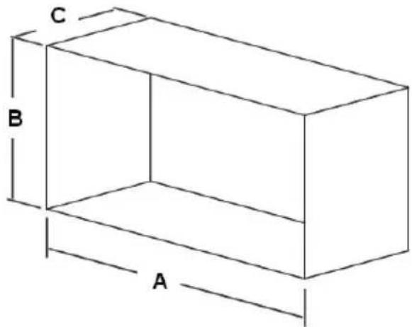
Minimum Cavity Dimensions
Where possible, it is recommended that the cavity is made slightly larger than the dimensions given to allow the installer the maximum amount of space to work in.
Minimum Cavity Dimensions
A
1010 mm
B
585 mm
C
330 mm
B3 Hearth
A hearth is not required. If one is installed, ensure that it meets the minimum clearances outlined in B6 "Clearance to Combustibles" on page 8.
B4 Cavity Base
This appliance MUST be fully supported on its base over the entire area of the underside of the appliance. The base must also be level and strong enough to support the total product weight.
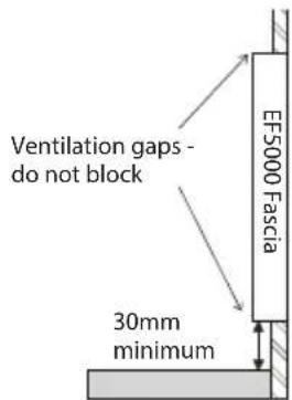
The EF5000 has ventilation gaps behind the fascia at the top and bottom. These MUST NOT be blocked. Ensure there is a gap of at least 30mm between the bottom of the fascia and anything below.
B5 Wall Cladding
The temperature of the wall directly above the fire can reach high temperatures.
It may discolour paint finishes. It is recommended to check the manufacturer's specifications for heat resistance prior to installing any cladding.
Some dark coloured exhaust stains may also become visible directly above the fire due to the exhaust. In most cases, this can be cleaned off with water and a brush.
B6 Clearance to Combustibles
The minimum clearance distance between a combustible ceiling and the fascia must be no less than 1400mm.
Warning: Under no circumstances should anything be closer than 1 meter in front of the EF5000, including: people, pets, or furniture.
Warning: Do not install a TV above the fire under any circumstances.

C
Types of Installations
C1 Freestanding Installation
This appliance is only to be used in an above ground, open-air situation with natural ventilation and without stagnant areas. Gas leakage and products of combustion must be rapidly dispersed by wind and natural convection.
Certain materials or items, when placed under or near the appliance, will be subjected to radiant heat and could become damaged.
In a freestanding installation, the appliance is installed in a completely unenclosed outdoor space with the appliance in an open and naturally ventilated area. To install the fire in a partially enclosed area, refer to sections C2 “Partially Enclosed Installations” on page 9 or C3 “Corner Installations” on page 10.
C2 Partially Enclosed Installations
If the fire is installed in an outdoor but partially enclosed structure, the structure should comply with one of the following suggestions. Rectangular areas have been used in the diagrams, however, the same principles would apply to other shaped areas.
In the case of balconies, at least 20% of the total wall area must remain open and unrestricted.
NOTE: Installation instructions for a partially enclosed installation are Escea recommendations only and may or may not comply with your local council standards. Please check with your local council for actual building standards.
Option 1: An enclosure with walls on all sides, but at least one permanent opening at ground level and no overhead cover.

Option 2: Within a partial enclosure that includes an overhead cover and no more than two walls.

Option 3: Within a partial enclosure that includes an overhead cover and more than two walls, provided it meets the following conditions:
- At least 25% of the total wall area is completely open, and
- At least 30% of the remaining wall area is open and unrestricted.


C3 Corner Installations
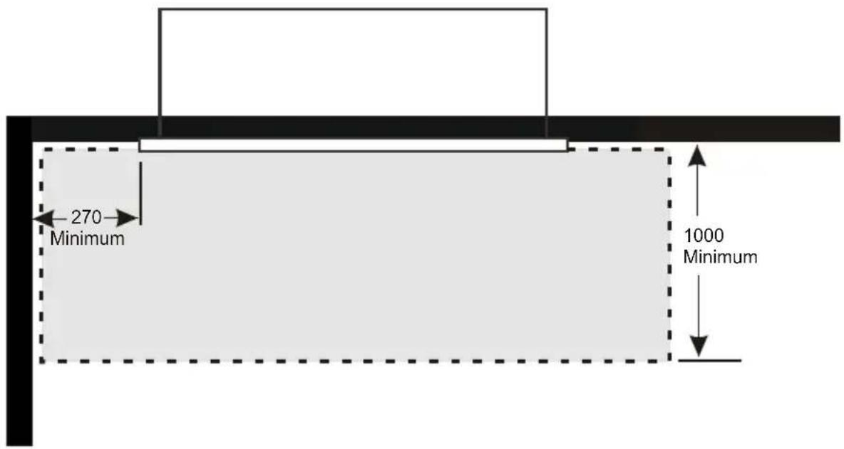
If a cavity is to be created in a corner, the following drawings provide the minimum interior wall dimensions.
NOTE: Allowances need to be made for cladding the internal parts of the cavity.

NOTE: Dimensions of the cavity in this diagram represent the internal size only. 10
The minimum clearance distance between adjacent walls and the edge of the fascia needs to be no less than 270mm.
END OF SECTION C
By the end of this section, you should have:
☐ A cavity with suitable clearances to combustibles and other walls.
☐ A suitably ventilated location for the appliance.
D Installing the Electricity and Gas to the Appliance
D1 Power Supply
The EF5000 requires a constant external 24V AC 1A power supply that is connected to mains power through the supplied transformer. The connection and the outlet must be protected against water ingress.
While the cavity is being created, consideration must be given to the location of an appropriate power supply. An earthed 230/240 volt mains power connection (typically a standard 3 pin outlet) must be available. This connection must be accessible after the heater has been fully installed so that the appliance can be safely disconnected from the mains power supply prior to servicing.
A mains isolation switch (compliant to AS:NZS 5601 Clause 6.2.8) which is accessible from outside the cavity can also be used to disconnect the power. Regardless of the method used, it MUST ALWAYS be possible to safely isolate the electrical supply to the appliance after it has been fully installed.
D2 Gas Pipe Sizing
Gas pipe should be sized as per the requirements of AS/NZS 5601/AG601-2000. The pipe sizing must be sufficient to deliver the following volume of gas to the heater with all other gas appliances in the home running at the same time:
Maximum EF5000 Gas Consumption - Natural Gas= 49MJ/hr Maximum EF5000 Gas Consumption - Propane = 40MJ/hr Maximum EF5000 Gas Consumption - ULPG = 40MJ/hr
D3 Gas Pipe Position
This fire has been supplied with a 1/2" pipe connected through a short 45° flare nut inlet connection to make the gas supply easy and safe. Solid pipe should be run to the inside lower left hand side of the fire. Insert the supplied rubber plug and cut it as shown below to allow the gas pipe and the electrical cable to pass through, keeping the plug as air-tight as possible.

Any flexible pipe should be attached to the copper supply pipe and joint tested to ensure gas tightness; an isolating valve is recommended for this purpose.
Before each use of the appliance, the hose assembly connecting the appliance to the gas supply must be inspected. If there is evidence of excessive abrasion or wear, or if the hose is damaged, then the hose assembly must be replaced before the appliance is operated.
The gas hose should be properly located away from pathways or areas where the hose may be subject to accidental damage.
D4 Gas Isolating Valve
It is highly recommended for a gas isolating valve to be installed in the gas line as close to the appliance as possible. Fix it in a convenient position to allow it to be closed off quickly and easily during normal operation. Take into consideration access to this valve once any wall cladding is installed. This will also allow for easier servicing in the future.
END OF SECTION D
By the end of this section, you should have:
☐ An unlined cavity with 230/240V AC supply where the appliance can be plugged into an electrical isolating switch that is accessible once the appliance is installed and is protected from water and the weather.
☐ A suitably sized gas supply to the appliance with a pressure test point, ready to be connected once the appliance is installed.
E
Installing the Appliance
E1 Installation
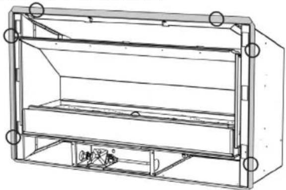
To fix the fire to the cavity, first drill 4 to 6 holes (5mm diameter) into the outer flange (shaded grey in the image below). The holes should be evenly spaced around the flange and drilled in locations which will provide the most support from the cavity framework behind the fire - suggested locations are circled in the diagram below. Using the supplied stainless steel screws, fasten the fire to the cavity through these drilled holes.
It is recommended that the outer flange is sealed to prevent water ingress into the cavity; high temperature silicon may be used.
Ensure that the fire is secure and free from movement.
E2 Connecting the Gas Pipe
When the EF5000 has been pushed into position and secured, the flexible hose can be connected to the inlet side of the appliance regulator at the front center of the fire. The hose and pipe assembly should have been tested as per section D3 “Gas Pipe Position” on page 12.
No matter which connection the installer chooses, the regulator that is supplied in the fire MUST NOT BE REMOVED. Removal of the regulator, or replacing it with one that is not intended for use with an Escea EF5000, will void the limited appliance warranty.
The EF5000 must be disconnected from the gas supply piping system during any pressure testing of that system at test pressures in excess of 3.5kPa (1/2 psi).
E3 Connecting the Power Supply and Power Switch
The power supply socket is located in the center line of the fire, below the firebox, facing the right hand side behind the ignition tray. Push the 2 pin plugs together until they click.
The ON/OFF power switch socket plugs into the 3 pin plug lead situated at the front right hand side of the fire. Push them together until they click.

E4 Gas Type Conversion
THIS APPLIANCE IS CONFIGURED TO OPERATE ON NATURAL GAS (NG). If gas type conversion is not required then skip to the next section.
Your gas fire has been supplied with the necessary parts for gas conversion. Follow the steps on the following pages to change from NG to ULPG/Propane or vice versa.
WARNING: The regulator that is supplied with the fire MUST NOT BE REMOVED.
Removal of the regulator, or replacing it with one not intended for use with this Escea fire, will void the limited appliance warranty.
Turn off power and gas first.
| Jets Burner Collars | |||||
| Front Burner | Rear Burner Pilot Front Burner Rear Burner | ||||
| Propane | ∅ 1.3mm ∅ | 1.3mm ∅ 0.30mm | ∅11mm Hole x 2 | ∅11mm Hole x 2 | |
| ULPG | ∅ 1.25mm | ∅ 1.25mm | ∅ 0.30mm | ∅11mm Hole x 2 | ∅11mm Hole x 2 |
| Natural Gas | ∅ 4.0mm | ∅ 4.0mm | ∅ 0.45mm | ∅5mm Hole x 2 - Collar must be fitted | ∅5mm Hole x 2 - Collar must be fitted |
The fascia, fuelbed, and stone cartridge should all be removed prior to doing the gas conversion.
Step 1: Remove the two screws holding the burner clamps in place. Remove the clamps. Lift out both burners to gain access to the burner jets.
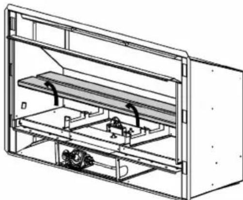
Step 2: Change the two jets with the conversion jets supplied in the kitset. Refer to the table at the start of this section to confirm jet sizes for each gas type.

Cover the existing gas type label with the new gas type label supplied in the kitset. Ensure that the serial number and the date of manufacture are still visible. Write your name, company (if appropriate), and date of conversion on the new label with permanent marker.

Step 3: Remove the four screws from the black infill panel and remove the panel. Undo the flexible gas tube that is connected to the engine. Remove all screws that are holding the engine in place and remove the engine from the fire.
Step 4: Remove the 6 screws from the engine cover (2 on each side, 2 on the top back) and slide the cover off. Also remove the 1 screw from the back panel and remove the back panel.

Step 5: Disconnect the blue and white wires between the pilot assembly and the rest of the tray. Use a 1/2" spanner to remove the nut from the pilot tube on the base of the tray.
Remove the brass nuts from the top of the gas pipes with a 5/8" spanner.
Lift the top pilot box assembly off of the lower engine.

Step 6: Undo the 4 screws from the pilot box and remove the box assembly.

Step 7: Remove the 2 screws from the pilot box and pull the cover off.

Step 8: Remove the 2 machine screws from the pilot assembly to remove the electrode assembly from the cover - they are held in by two bolts that can be removed with an 8mm spanner.

Step 9: Remove the two bolts from the bracket to allow for replacement of the pilot shroud and electrodes.

Step 10: Replace all components as required. If the pilot jet is being replaced, removed the existing jet from the pilot tube and replace with a new jet.
Note: The pilot jet for LPG has a red stripe on it; the pilot jet for natural gas does not.
Place the electrodes and the pilot shroud back into the bracket.
Warning: Be aware of the orientation of the pilot hood and the spacing between the electrode and flame sense. Also ensure that the collar hole on the pilot jet is open.

Reinstall the pilot and control tray by reversing the previous steps. Reattach the flexible gas hose to the engine.
Step 11: Take the regulator spring out of the regulator by unscrewing the pressure adjustment knob completely. Swap the regulator spring with the new spring that is supplied in conversion kitset. Replace adjustment screw and reset gas pressure (detailed in section E6 “Checking the Gas Operating Pressure” on page 20.

Step 12: Fit the appropriate burner collars to the burner for the correct gas type. Refer to the table at the start of this section for more information about burner collars.
For a Natural gas to Propane/ULPG conversion remove the restrictor collars from the burners.
For a Propane/ULPG to Natural Gas conversion you will need to fit the natural gas restrictor collars. These slide over the burner tube on the underside of the burners, and must be screwed into place so that the porting holes line up.

Step 13: Reinsert the burners and fix them back in place with the burner clamps.
E5 Operating the Appliance
Important: Test the power switch and spark ignition before the operating pressure is checked or the fascia is fitted.
The fire is operated by a power switch that is located on the fascia. Testing the power switch and spark ignition can be done with the gas supply either turned on or off.
With the power supply and power switch connected, lean the fascia beside the fire so that the right end is up and the tactile control pad is visible. Run through the steps for igniting the pilot, found in section F6 “Operating the Appliance” on page 25.
E6 Checking the Gas Operating Pressure
Note: Ensure that the jets match the gas type that is being used. See section E4 "Gas Type Conversion" on page 15 if necessary.
Turn on the gas. Turn the power on. Check the inlet pressure upstream of the appliance.
NOTE: The regulator that is supplied with the fire MUST NOT BE REMOVED. Removal of the regulator, or replacing it with one not intended for use with an Escea fire, will void the limited appliance warranty and may be dangerous.
Test the operating pressure using test point C on the regulator shown below. The regulator is located at the lower front of the appliance. This must be done before the fascia has been fitted.
The operating pressure has been factory set. Please check that the operating pressure is exactly as listed below and, if not, adjust the screw in the centre of the regulator (point B) until the pressure is correct. If unable to do this, reassess the inlet gas pressure/pipes.

A - Inlet Gas Connection
B - Pressure Adjustment Screw
C - Operating Pressure Test Point
Gas Pressure Table Gas Type
ULPG Propane Natural Gas
| Minimum Inlet Pressure - Pre-Regulator 2.5 kPa 2.5 kPa 1.0 kPa | |||
| Maximum Inlet Pressure - Pre-Regulator 5.0 kPa 5.0 kPa | 5.0 kPa | ||
| Operating pressure - Post-Regulator (Point C) | 2.2 kPa | 2.0 kPa | 1.0 kPa |
Once the pressure reading is correct, replace the operating test point screw and leak-test the test point.
Test the appliance for overall soundness using an appropriate method.
END OF SECTION E
By the end of this section, you should have:
☐ The appliance installed in the cavity
☐ The appliance plugged into a mains electricity supply
☐ Gas conversion completed (if necessary)
☐ The appliance gas supply attached and pressure tested with all other gas appliances running
F
Finishing the Installation
F1 Assembly of the Stone Cartridge
The glass which fits inside the stone cartridge has been packaged to protect it during transit; it can be found inside the firebox. Insert the glass strip into the stone cartridge between the two metal flanges and push it all the way to the bottom (as shown below).

With the glass in position, fix the stone cartridge to the fire by using the two supplied screws (circled in the diagram below). This must be done before the fascia is fitted. A bag of pebbles (river stones) are also supplied. Use these to fill the stone cartridge.

F2 Fitting the Fascia
Before fitting the fascia, the hooks must be attached using the screws supplied. Ensure the wires connecting the fascia to the fire are securely connected, as per section E3 “Connecting the Power Supply and Power Switch” on page 14.
The EF5000 fascia is attached to the combustion box by four 'hooks' on the corners of the fascia.
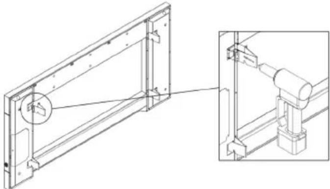
Line up the hooks with the receptacles on the outdoor fire, as pictured, and push the fascia into position. The first slot in the hook can be used to hang the fascia in the receptacles in order to facilitate the attachment.
When the fascia has been pushed in as far as it will go, briefly push down on the fascia to secure it into position.

F3 Placement of Ceramic Stones
The EF5000 fuelbed should be evenly spread out with a maximum of one layer of fuelbed media. Do not heap or mound the fuel bed media and attempt to get an even spread across the top of the burners.
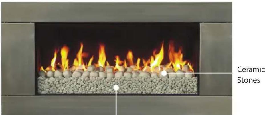
River Stones
Warning: Under no circumstances should the supplied small stone pebbles (river stones) be placed on the burners. They are for inside the stone cartridge ONLY.
Objects such as wood, coal, fire logs, or any other solid fuels shall not be burned in the gas fireplace.
Under no circumstances should any part of your body enter the gas fireplace during the start-up or while the fire is running.
F4 Pilot Flame and Burner Positioning
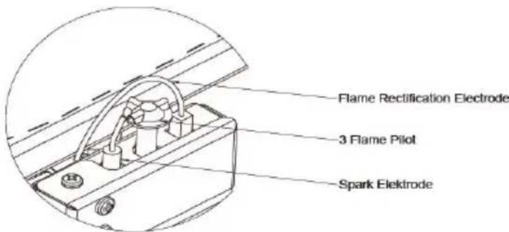
The pilot and burners are shown in the image below.

It is recommended to have a minimal gap (approximately 3 to 5 mm) between the spark electrode and the flame rectification electrode, as shown in the image below. It is also crucial to ensure that the flame rectification electrode is centred between the pilot shroud guards on either side.
F5 Weather Cover (Optional)
If desired, an optional weather cover can be purchased from your Escea retailer, which protects the fuelbed and burners. This should only be placed while the fire is not in use.
To fit the weather cover, ensure that the fire is o and cooled. Place the front edge on the glass at the front of the fire; the rear flange of the weather cover will rest on the burner supports behind the rear burner. To remove the weather cover, lift it upwards and away from the fire.
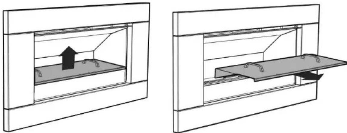
Warning: The fire MUST NOT be operated while the cover is fitted.
Warning: The cover MUST NOT be fitted while the fire is hot. A cooling period of 30 minutes must be observed before fitting.
F6 Operating the Appliance
The EF5000 is operated by an ON/OFF switch located on the right hand outer edge of the fascia.
Before operating the fire, ensure the power transformer is plugged into the mains wall socket and turned on; also ensure that the supply is turned on.

To turn the fire on, push the ON/OFF rocker switch to the open position. The ignition unit will start sparking and the pilot and burners will ignite almost immediately.
If there is no gas, the ignition unit will attempt to light up to three times before shutting down.
To turn off the fire, flick the ON/OFF rocker switch to the off position. This will shut down the gas flow to the pilot flame and both burners.
Please ensure that the gas supply is also turned off. As an extra safety, also turn off the main power supply at the house.

For further operation instructions please refer to the User Guide.
F7 Normal Operating Sounds and Smells
Sounds
It is possible that you will hear some sounds from your gas appliance. This is perfectly normal due to the fact that various types of materials are used within your appliance. Listed below are some examples. These are all normal operating sounds and should not be considered as defects in your appliance.
Gas Control Valve
As the gas control valves turn ON and OFF, a dull clicking sound may be audible. This is the normal operation of a valve. When the fire is switched off after being run for a while, there may be popping and fluttering noises as the residual gas in the burners burns away. These are normal and are no cause for concern.
Unit Body/Firebox
Different types and thicknesses of steel will expand and contract at different rates resulting in some “cracking” and “ticking” sounds being heard throughout the heating and cool down processes.
Smells
The first few times the unit is operated, the unit may release an odour and the flames will appear orange due to: the curing of the paint, the burning off of the starch in the gas logs, and the oils in the metal. This is a temporary curing process which will disappear with use.
The products of combustion are vented out the front of the fire. When installed in a well-ventilated outdoor space it is rare to smell these products, however, it is possible.
Go through the following checklist to ensure you have installed the appliance correctly
□ Correctly sized cavity
☐ Correct clearances to combustibles
☐ An electrical isolating switch to the appliance, accessible after finished installation
☐ Correctly sized gas supply with a pressure test point, ensuring adequate supply with all other gas appliances in the dwelling running
☐ Gas type conversion process carried out if required
☐ A weather-tight 240V supply with the 240/24V transformer protected from the elements
☐ The appliance fixed to the cavity
☐ The appliance plugged into a mains electricity supply
☐ All gas joints and pressure points leak tested with suitable leak detection solution and drop tests completed on gas pipework
☐ Fuel bed correctly installed
A fitted fascia
☐ Operated the fire and verified that it lights reliably and safely
☐ Data label marked up with correct gas type and dated by installer if converted during installation
Home-owner shown how to operate the appliance correctly
☐ Warranty card filled in with installer details and appliance serial number
☐ User Guide made available for end user
☐ Plumbing Industry Commission Compliance Certificate given to end user
S
Service Manual
IMPORTANT:
• This appliance must be serviced every 12 months.
- Any service operation should be carried out only by a suitably qualified and trained person.
- Gas and electricity supply MUST be isolated before any service operation is carried out on this appliance.
• This manual should be left with the appliance.
• Only use Escea approved spare parts.
- Spare parts are available from an Escea Distributor or Retailer
• DO NOT MODIFY THIS APPLIANCE.
S1 Annual Service Procedure
☐ Isolate power and gas supply to fire.
☐ Remove fuel bed and brush off any soot.
☐ Clean electrodes and pilot of any carbon build up and ensure correct gaps between electrodes and pilot.
☐ Remove burners and blow compressed air through the burner ports.
☐ Remove jets and clean injector hole with solvent.
□ Vacuum any dust from the underside of the fire box around the valve.
☐ Test all joints for gas tightness.
☐ Reassemble heater and check that operating pressure is correct.
☐ Trial heater with several start/stop cycles.
To access the product data plate, remove the fascia. Product information is located inside the fire on the bottom right hand side beside the engine.
S2 Maintenance and Cleaning
The unit must be cold before starting any form of maintenance or cleaning. To remove the glass and stones in the front stone tray, reverse the steps in section F1 “Assembly of the Stone Cartridge” on page 22 and F3 “Placement of Ceramic Stones” on page 23. The glass can be cleaned using any standard window cleaner and the quartz river stones can be washed using soapy water.
Periodically, the pilot and burners should be checked visually for carbon and soot build-up, consistent flame, and clean burning.
Cleaning of the burners and ceramic stones can be carried out using a brush and a dry cloth. This should be done at least annually to remove carbon or soot buildup.
EF5000 Exploded View
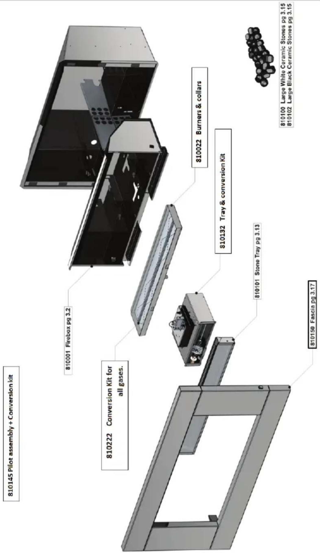
S4 Operation Chart
![graph TD A["ON / OFF Switch"] --> B["Check Gas Supply"] A --> C["Check Isolating Valve, if installed"] A --> D["First time use? Follow instructions for purging air in section 17.0 of the installation manual"] A --> E["Spark, but No Flame"] F["ON / OFF Switch"] --> G["Pilot Sparks, And Ignites"] F --…](/content/2026/05/954484/images/95a5d18b2fad364b251863a81bdbfcff3aefe826939c8c0c34df093a54820d4f.jpg)
S5 Cleaning the Fuelbed and Fascia
ALWAYS USE GLOVES WHEN HANDLING THE FASCIA.
Use a soft brush to clean the fuel bed media, being careful to replace it according to the instructions in section F3 “Placement of Ceramic Stones” on page 23.
If soot build up on the fuelbed becomes excessive or regular then one of the following actions may be required:
- Reset the gas pressure - pressure may be too high;
- Reposition the fuelbed;
- Clear any blockage from primary aeration port of burners.
The outside of an Escea Fascia must only be cleaned with a soft microfibre cloth. If heavier cleaning is required for the likes of grease or stubborn fingerprint removal we recommend the use of a dedicated stainless steel cleaner for stainless steel fascias or warm soapy water for powder coated fascias.
- Ensure that the gas fireplace is off and that the fascia is cold to the touch.
- Using a stainless steel cleaner and a clean cloth, apply a small amount of cleaner to the cloth and wipe the fascia with even, straight strokes.
-
Make sure your strokes follow the direction of the grain or brush finish. Wiping across the grain can leave small scratches.
-
The cleaner will leave a very fine film over the fascia, ensure this film is distributed evenly.
- If the cleaner is applied too heavily and is quite visible, you can remove the excess by gently wiping dry with a microfibre cloth. Ensure your strokes still follow the direction of the grain or brush finish.
- Ensure that no film is applied to the glass of your Escea Gas Fireplace. If applied accidentally, wipe off with an absorbent microfibre cloth.
For Powder Coated Fascias:
- Ensure that the gas fireplace is off and that the fascia is cold to the touch.
- Gently clean the fascia with a cloth and warm soapy water.
- Wipe off with an absorbent microfibre cloth.
S6 Checking Operating Pressure
See section E6 "Checking the Gas Operating Pressure" on page 20 of this manual.
S7 Replacing the Burners
Remove the fascia and fuelbed by reversing the steps in sections F2 “Fitting the Fascia” on page 22 and F3 “Placement of Ceramic Stones” on page 23. Remove the burners and replace them with the spare parts provided.
S8 Serial Number
The data label containing all technical information such as manufacture date, serial number, gas type, jet size, and other information can be found below the firebox in the lower right hand side of the fire. To access this, the fascia must be removed.
S9 Removing the Control Tray
- Isolate power and gas to the fire. Lift the fascia and hang it in the second slot. Unplug the fascia leads and fully remove the fascia from the firebox by lifting up and outwards.

- Remove all of the fuelbed media and the two screws holding the burner in place.

- Remove the two screws holding the stone tray in place and lift it out.
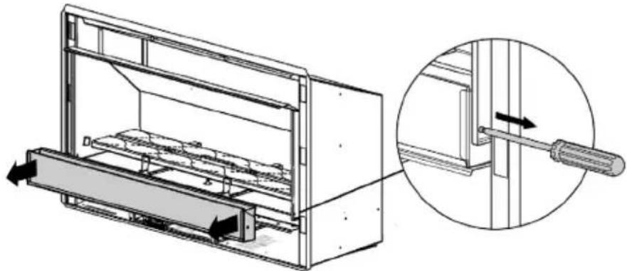
- Lift out both burners. Remove the four screws from the black infill panel and remove the panel. Undo the flexible gas tube that is connecting to the engine. Remove all screws that are holding the engine in place.

- Remove the control tray from the fire.
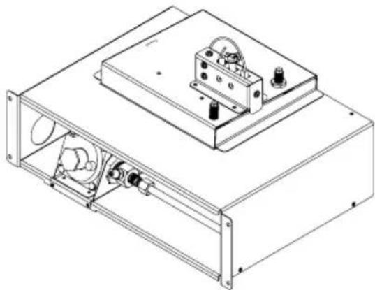
S10 Wiring Diagram

| B | ACDEFG |
- INSTALLATION / SERVICE INSTRUCTIONS
- IMPORTANT
- WARNING
- THIS MANUAL IS ONLY FOR FIRES WITH A SERIAL NUMBER FROM 81000 ONWARDS
- WHO CAN INSTALL THIS PRODUCT
- WARRANTY REPAIR AND ANNUAL SERVICING
- A PRODUCT DESCRIPTION AND INSTALLATION PROCESS 6
- B CREATING THE CAVITY 7
- C TYPES OF INSTALLATIONS 9
- D INSTALLING THE ELECTRICITY AND GAS TO THE APPLIANCE 12
- E INSTALLING THE APPLIANCE 14
- F FINISHING THE INSTALLATION 22
- G INSTALLATION CHECKLIST 27
- A
- PRODUCT DESCRIPTION AND INSTALLATION PROCESS
- A1 PRODUCT DESCRIPTION
- A2 RECOMMENDED INSTALL PROCESS
- A3 PRODUCT DIMENSIONS
- B
- CREATING THE CAVITY
- B1 CAVITY SHAPE
- B2 DESIGNING THE CAVITY
- THE EF5000 IS FOR OUTDOOR USE ONLY
- MINIMUM CAVITY DIMENSIONS
- B3 HEARTH
- B4 CAVITY BASE
- B5 WALL CLADDING
- B6 CLEARANCE TO COMBUSTIBLES
- C
- TYPES OF INSTALLATIONS
- C1 FREESTANDING INSTALLATION
- C2 PARTIALLY ENCLOSED INSTALLATIONS
- C3 CORNER INSTALLATIONS
- END OF SECTION C
- D INSTALLING THE ELECTRICITY AND GAS TO THE APPLIANCE
- D1 POWER SUPPLY
- D2 GAS PIPE SIZING
- D3 GAS PIPE POSITION
- D4 GAS ISOLATING VALVE
- END OF SECTION D
- E
- INSTALLING THE APPLIANCE
- E1 INSTALLATION
- E2 CONNECTING THE GAS PIPE
- E3 CONNECTING THE POWER SUPPLY AND POWER SWITCH
- E4 GAS TYPE CONVERSION
- WARNING: THE REGULATOR THAT IS SUPPLIED WITH THE FIRE MUST NOT BE REMOVED
- E5 OPERATING THE APPLIANCE
- E6 CHECKING THE GAS OPERATING PRESSURE
- END OF SECTION E
- F
- FINISHING THE INSTALLATION
- F1 ASSEMBLY OF THE STONE CARTRIDGE
- F2 FITTING THE FASCIA
- F3 PLACEMENT OF CERAMIC STONES
- F4 PILOT FLAME AND BURNER POSITIONING
- F5 WEATHER COVER (OPTIONAL)
- F6 OPERATING THE APPLIANCE
- F7 NORMAL OPERATING SOUNDS AND SMELLS
- SOUNDS
- GAS CONTROL VALVE
- UNIT BODY/FIREBOX
- SMELLS
- S
- SERVICE MANUAL
- S1 ANNUAL SERVICE PROCEDURE
- S2 MAINTENANCE AND CLEANING
- S4 OPERATION CHART
- S5 CLEANING THE FUELBED AND FASCIA
- FOR POWDER COATED FASCIAS
- S6 CHECKING OPERATING PRESSURE
- S7 REPLACING THE BURNERS
- S8 SERIAL NUMBER
- S9 REMOVING THE CONTROL TRAY
Brand : Escea
Model : EF5000
Category : Heating