RCI EW8310 - Serrure électromagnétique Dormakaba - Free user manual and instructions
Find the device manual for free RCI EW8310 Dormakaba in PDF.


| Product Type | Electromagnetic Lock with Early Warning System |
| Brand | Dormakaba (Rutherford Controls International) |
| Model | RCI EW8310 |
| Lock Dimensions (including bracket) | 2-1/8"D x 2-7/8"H x 10-13/16"L (54 mm x 73 mm x 275 mm) |
| Armature Plate Dimensions | 5/8"D x 2-3/8"H x 7-7/16"L (16 mm x 61 mm x 190 mm) |
| Power Input | Auto-sensing 12 VDC to 24 VDC |
| Power Consumption | 12 VDC: Max 0.58 A; 24 VDC: Max 0.29 A |
| Operation Mode | Fail Safe (locked when power is applied; releases on power loss) |
| Alarm Sequence | Nuisance delay (4 s), remote alarm period (30 s), forced open detection |
| Local Alarm Output | SPDT relay: 1.0 A at 120 VAC, 2 A at 30 VDC |
| Remote Alarm Output | DPDT relay: 1.0 A at 120 VAC, 2 A at 30 VDC |
| Status Indicators | Light panel (green/red) and optional external buzzer |
| Operating Temperature | 14°F to 140°F (-10°C to 60°C) |
| Environmental Rating | Indoor use only; not for outdoor environments |
| Certifications | cULus Listed as Auxiliary Lock; UL 10C (Positive Pressure Fire Test) for fire doors up to 4 ft wide x 8 ft high, rated up to 1-1/2 hr |
| Low Voltage Detection | Activates alarm if input drops below 9.0 VDC (factory enabled; can be disabled via jumper) |
| Anti-Tamper Feature | Two screws prevent access to mounting bolt holes |
| Mounting Accessories | Angle bracket, L bracket, filler bars, spacer bars, armature holder (sold separately) |
| Maintenance | Quarterly inspection of contacting surfaces and fasteners; clean with non-abrasive cleaner |
| Warranty | 10 years on magnet |
| Wire Gauge Recommendation | Refer to provided table for lengths up to 1500 ft (12V) or 1000 ft (24V) based on load current |
Frequently Asked Questions - RCI EW8310 Dormakaba
User questions about RCI EW8310 Dormakaba
0 question about this device. Answer the ones you know or ask your own.
Ask a new question about this device
Download the instructions for your Serrure électromagnétique in PDF format for free! Find your manual RCI EW8310 - Dormakaba and take your electronic device back in hand. On this page are published all the documents necessary for the use of your device. RCI EW8310 by Dormakaba.
USER MANUAL RCI EW8310 Dormakaba
In or Out... we make it Easy!
Pre-Installation Instructions
- This product must be installed according to all applicable building and life safety codes. All installations must be approved by the Authority Having Jurisdiction (AHJ).
- Due to the variety of mounting configurations available with this product, a survey and assessment of the physical area in which the product will be installed must be performed.
- The door frame must be inspected and deemed structurally sound prior to installation of the electromagnetic lock. The structural integrity of the mounting surfaces must be strong enough to meet or exceed the holding force of the product.
- The product must be protected from potential damage due to intruders or tampering.
- The product should be installed in a location that will not hinder or create a potential safety hazard to authorized personnel accessing the protected area.
- Because electromagnetic locks are used in a variety of applications and different door frame configurations, an experienced installer with knowledge of this product must make a determination of the optimal mounting method for this specific application.
- The components, hardware, installation instructions and mounting template included with this product are intended for use on outswinging doors.
PLEASE DELIVER ALL INSTALLATION INSTRUCTIONS TO THE END-USER UPON COMPLETION OF THE INSTALLATION.
- Do not install this product on the exterior of buildings.
- Do not use as a doorstop. This will void warranty.
- Separate accessories not included with this product must be used in the following applications:
- Narrow head jamb situations or center-hung doors
- Wherever there is insufficient space on the door frame header to mount the lock
- Hollow metal or wood frames where the door stop is not thick enough to allow the product to be installed
• Wherever an obstruction in the door prevents installation of the armature plate at a proper height - Doors that do not permit the armature plate to be mounted low enough to meet the magnet surface
Refer to the Product Accessories Guide section of the Installation Instructions for further information. Accessories may impact holding force.
-
Installation of this product should be done by an experienced installer with knowledge of this product.
-
A mechanical latching device is recommended in conjunction with the Early Warning 8310 to maintain security during a power failure.
NOTE: It is highly recommended that thread locking compound be applied to all screws during installation to reduce chance of screws loosening over extended time.
Installation Instructions
- Mount the electromagnetic lock to the door frame as outlined on the installation template included with the product.
Armature Plate Mounting Notes:
1) It is essential that this plate pivot slightly on the mounting bolt to allow proper alignment with the magnet surface. If not aligned, the lock may lose holding force or not lock at all.
2) The rubber washer on the head of the mounting bolt should project slightly beyond the surface of the armature plate. It will expand when power is removed and break the air vacuum between the plate and magnet. If removed or trimmed, the lock will appear to have some holding force even when power is removed.
For added safety, thread locking compound has been provided for the armature plate bolt and the four captive electromagnetic lock mounting screws.
WARNING: Improper installation, maintenance, inspection or usage of the product or any related accessories or parts may cause the electromagnetic lock, armature plate and associated hardware to disengage and fall, causing serious bodily injury and property damage. Rutherford Controls Int'l Inc. and/or Rutherford Controls Int'l Corp. will not be liable to the installer, purchaser, end user or anyone else for damage or injury to person or property due to improper installation, care, storage, handling, maintenance, inspection, abuse, misuse or act of God or nature involving this product or any related accessories or parts.
-
Route the power supply connecting wire through the door frame and into the wire access hole in the top of the magnet housing. Connecting wire should be of sufficient gauge for the lock being installed and the distance being run. See table for current draw specifications and wiring gauge chart.
-
See system overview and switching options.
EW8310 Early Warning Electromagnetic Lock Installation Instructions (Continued)
Early Warning System – Overview
The Early Warning electromagnetic lock is a fail safe device.
In the normal condition with power, the door is locked, the light panel blinks green, the Local Alarm SPDT relay is de-energized and the Remote Alarm DPDT relay is energized.
The alarm sequence starts with a direct pull on the door.
A Nuisance Delay is set for 4 seconds. During this time the light panel will blink red and the Local Alarm relay will be energized to warn that someone is attempting to force open the secured lock. If the pressure on the door is withdrawn during the Nuisance Delay Period, the system returns to normal conditions. This would be considered accidental triggering.
If pressure is maintained past the Nuisance Delay Period, the Remote Alarm Period of 30 second will begin. In addition to the light panel blinking red and the energized Local Alarm, the Remote Alarm relay will now be de-energized.
At the end of the 30 second Remote Alarm Period, if the pressure has been withdrawn, the Local Alarm relay will return to the normal condition. The light panel however will continue to flash red and green until reset. The Remote Alarm relay will remain off until reset. If pressure is reapplied to the door, the system goes directly to the 30 second Remote Alarm Period activation of Local Alarm Relay.
If the door is forced open, the light panel will immediately blink red, the Local Alarm relay will be energized and the Remote Alarm relay will be de-energized. Even if the door is subsequently closed, all indicators will remain activated until the system power is turned off.
Easy connections are provided for an external sounder or buzzer. At an accidental triggering, an audible pulse is generated with a steady sound during the 30 second Remote Alarm period. A forced open status will provide a pulsing sound until reset.
Request to exit connections and access control wiring are detailed on pages 4 and 5.
Anti-Tamper Feature - Two screws prevent insertion of an Allen wrench into the captive mounting screw opening on the bottom of the lock. Fig. 1 shows their location. One screw also secures the wiring cavity cover. The mounting plate cannot be separated from the lock without removing these two screws.

EarlyWarningLock-StatusIndicators
| System Status Light Panel | Optional External Buzzer | Local Alarm Relay | Remote Alarm Relay | |
| Door Open Red on | OFF OFF OFF | |||
| Locked | Green blinks every 5 seconds | OFF OFF ON | ||
| 4 second Nuisance Delay Period | Red blinking (fast) Pulsing Sound ON ON | |||
| 30 second Remote Alarm Period | Red blinking (slowly) Steady Sound ON OFF | |||
| Alarm Requires Reset | Red/Green blinking alternately | Steady Sound OFF OFF | ||
| Forced Open* Red | blinking (fast) Pulsing Sound ON OFF | |||
| Exit Switch to Open Red | On OFF OFF OFF | |||
* A drop in voltage will also generate the same status indicators as forced open. Shutting down the system power is required for reset.
If power is removed entirely, the fail safe Early Warning Lock releases and all indicators shut down. The door is secured by the mechanical latching only until power is restored and the Early Warning Lock resets.
EW8310 Early Warning Electromagnetic Lock Installation Instructions (Continued)
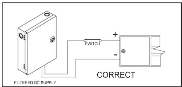

Fig. 2 – Power Connections
To Ensure Instant Release All switching devices must be wired in between the DC power source and the positive terminal of the lock as illustrated in Fig 2.
Switching the negative power supply line will not allow the lock to release immediately. RCI electromagnetic locks contain MOV's for surge suppression and do not require any additional suppression to be added during installation. The installation of diodes across the lock input terminals will cause a delay in release.
Low Voltage Detection
Each circuit board includes a low voltage detection circuit that is enabled when shipped from the factory. This feature will cause the Local Alarm relay and status LED to activate and the Remote Alarm relay to de-energize should the lock input voltage drop below 9.0VDC. That signals a monitored system or guard station that the holding force of the lock may have been compromised.
Specifications
LISTING cULus Auxiliary Lock. LISTED
This product has been successfully tested and evaluated by UL for use in both the United States and Canada.
Our GWXT fire listing qualifies the EW8310 series as an "Auxiliary Lock" for use with UL Classified fire doors maximum 4' in width and 8' in height, rated up to and including 1-1/2 hr with the "Positive Pressure Fire Test of Door Assemblies", ANSI/UL 10C.
Patents: US 8,292,337 and Canada 2,632,243
MECHANICAL:
EW8310 Lock Dimensions Including 1/4" (6.4mm) mounting bracket: 2-1/8"D x 2-7/8"H x 10-13/16"L (54mm x 73mm x 275mm)
EW8310 Armature Plate Dimensions: 5/8"D x 2-3/8"H x 7-7/16"L (16mm x 61mm x 190mm)
ELECTRICAL:
Auto Sensing Voltage: 12VDC to 24VDC
Power Consumption: 12VDC - Max 0.58A 24VDC - Max 0.29A
Local Alarm Output: SPDT 1.0A 120VAC, 2A 30VDC
Remote Alarm Output: DPDT: 1.0A 120VAC, 2A 30VDC
ENVIRONMENTAL:
Not for use in outdoor environments. Circuit board operating temperature: 14 to 140°F (-10 to 60°C)
NOTE: The EW8310 electromagnetic lock must be powered with a filtered and regulated DC power supply rated 12 to 24V. RCI recommends our 10 Series Power Supplies and full line of switching devices.
The magnet warranty is 10 years. Specifications subject to change without notice.
EW8310 Early Warning Electromagnetic Lock Installation Instructions (Continued)
Circuit Board Connections

HD4: N/O momentary request to exit switch (7 second built in release)
BZ: 9VDC output to Buzzer max 100mA
HD2: Same as Remote A below
JP2: Jumper off to enable low voltage detection (factory default)
Jumper on to disable low voltage detection
HD3 Main Harness
RST: Connect the brown and brown/white leads to reset switch
- DC: DC power wires; black is negative (-) and Red is positive (+)
Remote A Purple is common (C)
Orange is normally closed (NC)
Blue is normally open (NO)
Local: Grey is common (C)
Green is normally open (NO)
Pink is normally closed (NC)
Wiring Diagram
Diagram reflects status with power on and door opened.
A mechanical latching device is recommended in conjunction with the Early Warning 8310 to maintain security during a power failure.
![graph TD A["POWER SUPPLY (ORDER SEPARATELY)"] --> B["BROKEN LINES ARE FIELD WIRING"] B --> C["CONNECTIONS TO FIRE PANEL PER CODE"] C --> D["OPTIONAL AUDIBLE SIGNAL APPLIANCE (ORDER SEPARATELY)"] D --> E["AUDIO SELECT - SOUND PATTERNS 7, B, OR 9 ONLY FOR RCI MODEL 914"] E --> F["BROKEN LINES ARE FIEL…](/content/2026/05/953936/images/516aaefdd463d99c4a954bda3483cd80011514ffc2f7f3c1323bc650b6df9c9f.jpg)
EW8310 Early Warning Electromagnetic Lock Installation Instructions (Continued)
Alternate Access Control Wiring Diagram
Diagram reflects status with power on and door opened.
A mechanical latching device is recommended in conjunction
with the Early Warning 8310 to maintain security during a power failure.
NOTE: 1.) Unlock time is determined
by the access control device.
2.) The access control device must
be set for fail safe operation.
![graph TD A["HD4 H Harness"] --> B["MAIN HARNESS HD3"] B --> C["HD2"] C --> D["Purple COMMON HD2 HARNESS - REMOTE B"] C --> E["ORANGE NC HD2 HARNESS - REMOTE A"] C --> F["BZ HARNESS"] F --> G["NC PINK HD2 HARNESS - REMOTE B"] F --> H["NO GREEN HD2 HARNESS - REMOTE A"] F --> I["LOCAL COMMON GREY"] J["…](/content/2026/05/953936/images/cecc7c35992a30cc8f55f070902b6f316a6086e409201ea7884bd588b793c8e9.jpg)
Reset and Override Wiring for Double Doors
Diagram reflects status with power on and door opened

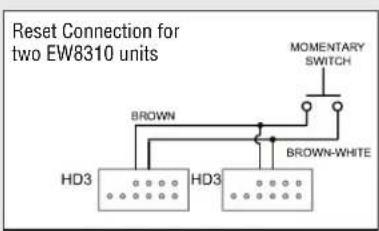
NOTE: By using either remote relay and the local relay, you can have the alarm sound after the nuisance delay for 30 seconds or if the door is forced open. Alarm will not sound in any other condition.

EW8310 Early Warning Electromagnetic Lock Installation Instructions (Continued)
Inspection and Maintenance
This product and all related accessories or parts must be inspected and maintained on a quarterly basis. Contacting surfaces of the electromagnetic lock and armature plate must be kept free of contaminating materials. Surfaces must be cleaned periodically with a non-abrasive cleaner.
All mounting fasteners must be inspected on a quarterly basis. When properly installed, the ends of the armature plate allow a slight movement but the plate will feel secure when grasped at the bolt. There should be no movement to the mounting bracket or housing of the electromagnetic lock.
For added safety, thread locking compound has been provided for the armature plate bolt and the four captive electromagnetic lock mounting screws.
WARNING: Improper installation, maintenance, inspection or usage of the product or any related accessories or parts may cause the electromagnetic lock, armature plate and associated hardware to disengage and fall, causing serious bodily injury and property damage.
PLEASE DELIVER ALL INSTALLATION INSTRUCTIONS TO THE END-USER UPON COMPLETION OF THE INSTALLATION.
EW8310 Early Warning Series Troubleshooting Guide
| PROBLEM | SOLUTION |
| Cannot remove the lock mounting bracket from top of magnet for installation. | Remove anti-tamper screw and cavity screw. Insert supplied Allen wrench into mounting bolt holes in the bottom of the lock housing and turn. (See Fig.1) |
| Lock is installed but has no holding force at all. | Check power supply. DC power should be within 12-24VDC.Check connections at power supply, connected releasing devices, lock terminals and lock circuit board to magnet core. |
| Lock has enough holding force to lightly hold a screwdriver or set of pliers but door will not lock. | Check to see that armature plate is correctly aligned with the electromagnetic lock.If there is improper alignment, make a 1/4” turn of the armature plate mounting bolt and check for alignment.Make sure to follow the armature mounting instructions on the template and page 1 of this install. |
| Lock is operating and locking but the armature plate is “humming” against the surface of the lock. | This generally indicates that the lock is either operating on AC voltage or there is some AC voltage present in the DC supply. A properly filtered and regulated DC power supply is required to achieve optimal operation from the lock. |
| Lock is not releasing immediately upon removal of power | Ensure that switching devices are interrupting the DC power and not the AC power supply voltage.Ensure rubber washer on armature plate mounting bolt has not been removed or damaged.Check that switching device interrupts the positive wire and not the negative wire (See Fig. 2).Remove any Diodes or other suppression devices that may be installed. |
EW8310 Early Warning Electromagnetic Lock Installation Instructions (Continued)
Product Mounting Accessories Guide
Accessories may impact holding force.
(Separate installation instructions provided with accessories.)
| PART USAGE | EXAMPLE | |
| Angle Bracket | Used in a narrow head jamb situation or for center-hung doors.Any place where there is insufficient frame depth to mount the lock.The Early Warning uses the same angle bracket as the RCI standard 8310.Available in several different sizes and finishes. |  |
| “L” Bracket | Required wherever there is insufficient space on the frame header to mount the lock. The lock mounts to the underside of the “L” bracket and the “L” bracket then gets mounted to the doorframe.Available in several different sizes and finishes. |  |
| Filler Bars | Used to provide extra mounting space in a hollow metal or wood frame where the door stop of the frame is not thick enough to allow a lock to be installed.The Early Warning uses the same filler bars as the RCI standard 8310.Available in several different widths. | 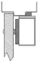 |
| Spacer Bars | For use when an obstruction in the door prevents the installation of the armature plate at a proper height. If the armature plate needs to be lowered then a spacer bar can be used to lower the lock from the frame.Available in several different thickness. |  |
| Armature Holder | For use with doors that do not permit the armature plate to be mounted low enough to meet the magnet surface. Eg: Some aluminum framed commercial glass doors. The armature holder can be mounted to whatever frame is available and the armature plate in turn mounted to the holder.Available in both flat (shown) and pocket styles. |  |
EW8310 Early Warning Electromagnetic Lock Installation Instructions (Continued)
WIRE GAUGE SELECTIONS
| Total One WayLength of Wire Run (ft.) | Load Current @24V | |||||||
| 1/4A | 1/2A | 3/4A | 1A | 1-1/4A | 1-1/2A | 2A | 3A | |
| 100 | 24 | 20 | 18 | 18 | 16 | 16 | 14 | |
| 150 | 22 | 18 | 16 | 16 | 14 | 14 | 12 | |
| 200 | 20 | 18 | 16 | 14 | 14 | 12 | 12 | |
| 250 | 18 | 16 | 14 | 14 | 12 | 12 | 12 | |
| 300 | 18 | 16 | 14 | 12 | 12 | 12 | 10 | |
| 400 | 18 | 14 | 12 | 12 | 10 | 10 | ||
| 500 | 16 | 14 | 12 | 10 | 10 | -- | ||
| 750 | 14 | 12 | 10 | 10 | -- | -- | -- | -- |
| 1000 | 14 | 10 | 10 | -- | -- | -- | -- | -- |
| 1500 | 12 | 10 | -- | -- | -- | -- | -- | -- |
12 10 10 10
| Total One WayLength of Wire Run (ft.) | Load Current @12V | |||||||
| 1/4A | 1/2A | 3/4A | 1A | 1-1/4A | 1-1/2A | 2A | 3A | |
| 100 | 20 | 18 | 16 | 14 | 14 | 12 | 12 | 10 |
| 150 | 18 | 16 | 14 | 12 | 12 | 12 | 10 | -- |
| 200 | 16 | 14 | 12 | 12 | 10 | 10 | -- | -- |
| 250 | 16 | 14 | 12 | 10 | 10 | 10 | -- | -- |
| 300 | 16 | 12 | 12 | 10 | 10 | -- | -- | -- |
| 400 | 14 | 12 | 10 | -- | -- | -- | -- | -- |
| 500 | 14 | 10 | 10 | -- | -- | -- | -- | -- |
| 750 | 12 | 10 | -- | -- | -- | -- | -- | -- |
| 1000 | 10 | -- | -- | -- | -- | -- | -- | -- |
| 1500 | 10 | -- | -- | -- | -- | -- | -- | -- |
Wire Gauge Chart courtesy of Electronic Locking Devices by John L. Schum
- PRE-INSTALLATION INSTRUCTIONS
- PLEASE DELIVER ALL INSTALLATION INSTRUCTIONS TO THE END-USER UPON COMPLETION OF THE INSTALLATION
- INSTALLATION INSTRUCTIONS
- EW8310 EARLY WARNING ELECTROMAGNETIC LOCK INSTALLATION INSTRUCTIONS (CONTINUED)
- EARLY WARNING SYSTEM – OVERVIEW
- LOW VOLTAGE DETECTION
- SPECIFICATIONS
- MECHANICAL
- ELECTRICAL
- ENVIRONMENTAL
- CIRCUIT BOARD CONNECTIONS
- HD3 MAIN HARNESS
- WIRING DIAGRAM
- ALTERNATE ACCESS CONTROL WIRING DIAGRAM
- INSPECTION AND MAINTENANCE
Brand : Dormakaba
Model : RCI EW8310
Category : Serrure électromagnétique