
CMXEGAR500 - Grinder Craftsman - Free user manual and instructions
Find the device manual for free CMXEGAR500 Craftsman in PDF.


| Product Type | 6" (150 mm) Bench Grinder |
| Brand | Craftsman |
| Model | CMXEGAR500 |
| Wheel Diameter | 6" (150 mm) |
| Arbor Size | 1/2" (13 mm) |
| No-Load Speed | 3,450 RPM |
| Grinding Wheels Included | Coarse (36 Grit) and Medium (60 Grit) |
| Motor Voltage | 120 V AC |
| Motor Current | 2.1 A |
| Weight | Approximately 13 lbs (5.9 kg) |
| Dimensions (L x W x H) | Approximately 12" x 8" x 10" (30 x 20 x 25 cm) |
| Material | Cast iron base, aluminum components |
| LED Work Lights | 2 battery-powered LED lights (uses 4 AAA batteries, not included) |
| Eye Shields | 2 adjustable eye shields |
| Tool Rests | 2 adjustable tool rests, right one with V-groove for drill bits |
| Spark Guards | 2 adjustable spark guards |
| Safety Features | Grounded plug, safety guards, eye shields, spark arrestors, warning labels |
| Warranty | 3-year limited warranty, 90-day money back guarantee |
| Included Accessories | 2 grinding wheels, 2 LED lights, 2 eye shields, 2 tool rest assemblies, 4 AAA batteries, user manual |
| Maintenance | Regular cleaning, replace batteries, dress grinding wheels, replace worn wheels |
Frequently Asked Questions - CMXEGAR500 Craftsman
User questions about CMXEGAR500 Craftsman
0 question about this device. Answer the ones you know or ask your own.
Ask a new question about this device
Download the instructions for your Grinder in PDF format for free! Find your manual CMXEGAR500 - Craftsman and take your electronic device back in hand. On this page are published all the documents necessary for the use of your device. CMXEGAR500 by Craftsman.
USER MANUAL CMXEGAR500 Craftsman
INSTRUCTION MANUAL | MANUAL DE INSTRUCTIONES
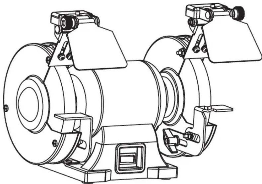
6" (150 mm) Bench Grinder 6" (150 mm) Amoladora de banco
natural_image
Technical line drawing of a dual-axis electric motor with mounting brackets (no text or symbols)CMXEGAR500
Definitions: Safety Alert Symbols and Words
This instruction manual uses the following safety alert symbols and words to alert you to hazardous situations and your risk of personal injury or property damage.

DANGER: Indicates an imminently hazardous situation which, if not avoided, will result in death or serious injury.

WARNING: Indicates a potentially hazardous situation which, if not avoided, could result in death or serious injury.

CAUTION: Indicates a potentially hazardous situation which, if not avoided, may result in minor or moderate injury.

(Used without word) Indicates a safety related message.
NOTICE: Indicates a practice not related to personal injury which, if not avoided, may result in property damage.
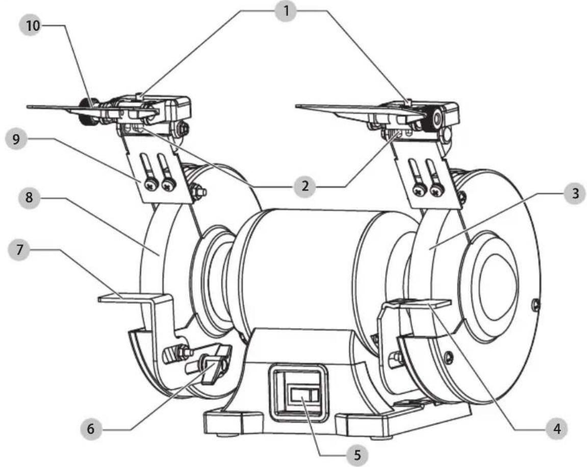
Fig. A
COMPONENTS
1 LED light ON/OFF switch
2 LED light
3 Medium grinding wheel (60 Grit)
4 Right tool rest assembly (V Grooved)
5 ON/OFF switch
6 Tool rest lock knob
7 Left tool rest assembly
8 Coarse grinding wheel (36 Grit)
9 Spark guards
10 Eye shield
PRODUCT SPECIFICATIONS
Wheel Diameter: 6" (150 mm)
Arbor: 1/2" (13 mm) RPM Speed 3,450

WARNING: Read all safety warnings and all
instructions. Failure to follow the warnings and instructions may result in electric shock, fire and/or serious injury.

WARNING: Never modify the product or any part of it. Damage or personal injury could result.

WARNING: To reduce the risk of injury, read the instruction manual.
If you have any questions or comments about this product, call CRAFTSMAN toll free at: 1-888-331-4569.
6" (150 mm) Bench Grinder CMXEGAR500
GENERAL POWER TOOL SAFETY WARNINGS
WARNING: Read all safety warnings, instructions, illustrations and specifications provided with this power tool. Failure to follow all instructions listed below may result in electric shock, fire and/or serious injury.
SAVE ALL WARNINGS AND INSTRUCTIONS FOR FUTURE REFERENCE
The term "power tool" in the warnings refers to your mains-operated (corded) power tool or battery-operated (cordless) power tool.
1) Work Area Safety
a) Keep work area clean and well lit. Cluttered or dark areas invite accidents.
b) Do not operate power tools in explosive atmospheres, such as in the presence of flammable liquids, gases or dust. Power tools create sparks which may ignite the dust or fumes.
c) Keep children and bystanders away while operating a power tool. Distractions can cause you to lose control.
2) Electrical Safety
a) Power tool plugs must match the outlet. Never modify the plug in any way. Do not use any adapter plugs with earthed (grounded) power tools. Unmodified plugs and matching outlets will reduce risk of electric shock.
b) Avoid body contact with earthed or grounded surfaces such as pipes, radiators, ranges and refrigerators. There is an increased risk of electric shock if your body is earthed or grounded.
c) Do not expose power tools to rain or wet conditions. Water entering a power tool will increase the risk of electric shock.
d) Do not abuse the cord. Never use the cord for carrying, pulling or unplugging the power tool. Keep cord away from heat, oil, sharp edges or moving parts. Damaged or entangled cords increase the risk of electric shock.
e) When operating a power tool outdoors, use an extension cord suitable for outdoor use. Use of a cord suitable for outdoor use reduces the risk of electric shock.
f) If operating a power tool in a damp location is unavoidable, use a ground fault circuit interrupter (GFCI) protected supply. Use of a GFCI reduces the risk of electric shock.
3) Personal Safety
a) Stay alert, watch what you are doing and use common sense when operating a power tool. Do not use a power tool while you are tired or under the influence of drugs, alcohol or medication. A moment of inattention while operating power tools may result in serious personal injury.
b) Use personal protective equipment. Always wear eye protection. Protective equipment such as dust mask, non-skid safety shoes, hard hat, or hearing protection used for appropriate conditions will reduce personal injuries.
c) Prevent unintentional starting. Ensure the switch is in the off position before connecting to power source and/or battery pack, picking up or carrying the tool. Carrying power tools with your finger on the switch or energizing power tools that have the switch on invites accidents.
d) Remove any adjusting key or wrench before turning the power tool on. A wrench or a key left attached to a rotating part of the power tool may result in personal injury.
e) Do not overreach. Keep proper footing and balance at all times. This enables better control of the power tool in unexpected situations.
f) Dress properly. Do not wear loose clothing or jewelry. Keep your hair, clothing and gloves away from moving parts. Loose clothes, jewelry or long hair can be caught in moving parts.
g) If devices are provided for the connection of dust extraction and collection facilities, ensure these are connected and properly used. Use of dust collection can reduce dust-related hazards.
h) Do not let familiarity gained from frequent use of tools allow you to become complacent and ignore tool safety principles. A careless action can cause severe injury within a fraction of a second.
4) Power Tool Use and Care
a) Do not force the power tool. Use the correct power tool for your application. The correct power tool will do the job better and safer at the rate for which it was designed.
b) Do not use the power tool if the switch does not turn it on and off. Any power tool that cannot be controlled with the switch is dangerous and must be repaired.
c) Disconnect the plug from the power source and/or remove the battery, pack if detachable, from the power tool before making any adjustments, changing accessories, or storing power tools. Such preventive safety measures reduce the risk of starting the power tool accidentally.
d) Store idle power tools out of the reach of children and do not allow persons unfamiliar with the power tool or these instructions to operate the power tool. Power tools are dangerous in the hands of untrained users.
e) Maintain power tools and accessories. Check for misalignment or binding of moving parts, breakage of parts and any other condition that may affect the power tool's operation. If damaged, have the power tool repaired before use. Many accidents are caused by poorly maintained power tools.
f) Keep cutting tools sharp and clean. Properly maintained cutting tools with sharp cutting edges are less likely to bind and are easier to control.
g) Use the power tool, accessories and tool bits, etc. in accordance with these instructions, taking into account the working conditions and the work to be performed. Use of the power tool for operations different from those intended could result in a hazardous situation.
h) Keep handles and grasping surfaces dry, clean and free from oil and grease. Slippery handles and grasping surfaces do not allow for safe handling and control of the tool in unexpected situations.
5) Service
a) Have your power tool serviced by a qualified repair person using only identical replacement parts. This will ensure that the safety of the power tool is maintained.
BENCH GRINDER SAFETY


Wear eye protection that complies with ANSI Z87.1 specifications.
• Use grinding wheels suitable for the speeds of the grinder.
- Stand beside the bench grinder during start-up, not facing directly in front.
- Do not remove the wheel guard.
- Do not use the grinding wheel to cut anything.
- Do not use anything to stress the grinding wheel.
- Use a grinding wheel dressing tool to shape or remove glaze from grinding wheels.
- Adjust distance between wheel and tool rest to maintain 1/8 inch (3.2 mm) or less separation as the diameter of the wheel decreases with use.
- Connect to a supply circuit protected by a circuit breaker or time-delay fuse.
- Secure the bench grinder to its supporting surface to prevent the grinder from tipping over, sliding, or walking on its supporting surface.
A. Replace a cracked wheel immediately.
B. Always use the guards and eye shields.
C. Do not overtighten the wheel nut.
D. Use only flanges furnished with this grinder.
• Always inspect grinding wheels prior to use for cracks, missing pieces, etc. Replace wheel immediately before use.
• USE ONLY GRINDING WHEELS that comply with ANSI B7.1 and rated greater than 3450 RPM.
- GUARD AGAINST ELECTRICAL SHOCK by preventing body contact with grounded surfaces. For example: pipes, radiators, ranges, refrigerator enclosures.
- DO NOT use wheels with incorrect size holes. NEVER use wheel washers or wheel screws that are defective or incorrect, and NEVER touch a grinding wheel or other moving parts.
- NEVER reach to pick up a workpiece, a piece of scrap, or anything else that is in or near the grinding path of the wheel.
- AVOID AWKWARD OPERATIONS AND HAND POSITIONS where a sudden slip could cause your hand to move into the wheel. ALWAYS make sure you have good balance.
- NEVER stand or have any part of your body in line with the path of the wheel.
- DO NOT USE TOOL IF SWITCH DOES NOT TURN IT ON AND OFF. Have defective switches replaced by an authorized service center.
- DO NOT TURN THE MOTOR SWITCH ON AND OFF RAPIDLY. This could cause the wheel to loosen and create a hazard. Should this ever occur, stand clear and allow the wheel to come to a complete stop. Disconnect your grinder from the power supply and retighten the wheel nut securely.
- RISK OF INJURY DUE TO ACCIDENTAL STARTING. Do not use in an area where children may be present.
- NEVER START THE GRINDER when the wheel is in contact with the workpiece.
- SECURE WORK. Always hold the workpiece firmly against the work rest.
- DO NOT USE THE BENCH GRINDER if the flange nut or clamp nut is missing or if the spindle shaft is bent.
- FREQUENTLY clean grinding dust from beneath the grinder.
• DO NOT OPERATE THIS TOOL WHILE UNDER THE INFLUENCE OF DRUGS, ALCOHOL OR ANY MEDICATION.
- ALWAYS STAY ALERT. Do not allow familiarity (gained from frequent use of your grinder) to cause a careless mistake. ALWAYS REMEMBER that a careless fraction of a second is sufficient to inflict severe injury.
- STAY ALERT AND EXERCISE CONTROL. Watch what you are doing and use common sense. Do not operate the tool when you are tired. Do not rush.
- SAVE THESE INSTRUCTIONS. Refer to them frequently and use them to instruct other users. If you loan someone this tool, loan them these instructions also.
English
- ALWAYS EASE THE WORKPIECE AGAINST THE ABRASIVE WHEEL when starting to grind. A harsh impact can break the wheel. Use light pressure when starting to grind. Too much pressure on a cold wheel can cause the wheel to crack.
- USE ONLY FLANGES furnished with this bench grinder.
- IF ANY PART OF THIS GRINDER IS MISSING or should break, bend, fail in any way, or should any electrical component fail to perform properly, shut off the power switch, remove the machine plug from the power surce and have damaged, missing, or failed parts replaced before resuming operation.
- SAFETY SHIELD AND SPARK DEFLECTOR. The safety shields and spark deflectors are adjustable for operator convenience. Operating the grinder without these features attached could result in serious injury. Do not grind with the safety shield raised. Always wear safety glasses for personal protection.
- WORK REST. The work rests are independently adjustable to compensate for wheel wear. Before grinding, make certain the work rests are adjusted properly. Generally, the object being ground is done slightly above the center of the grinding wheel.
- Lawn mower blades are usually sharpened on only one edge and dressed up slightly on the other. Perform this sharpening process on both cutting ends of the blade. After sharpening, balance the blade by removing additional material.
PROPOSITION 65 WARNING
WARNING: Some dust created by power sanding, saving, grinding, drilling, and other construction activities contains chemicals known to the State of California to cause cancer, birth defects or other reproductive harm. Some examples of these chemicals are:
- Lead from lead-based paints,
- Crystalline silica from bricks and cement and other masonry products, and
- Arsenic and chromium from chemically-treated lumber.
Your risk from these exposures varies depending on how often you do this type of work. To reduce your exposure to these chemicals: work in a well ventilated area and work with approved safety equipment, such as those dust masks that are specially designed to filter out microscopic particles.
Handling the power cord on this product may expose you to chemicals known to the state of California to cause cancer and birth defects or other reproductive harm. Wash hands after handling.
For more information go to: www.P65Warnings.ca.gov

READ INSTRUCTION MANUAL: To reduce the risk of injury, user and all bystanders must read instruction manual before using this product.
- Avoid prolonged contact with dust from power sanding, sawing, grinding, drilling, and other construction activities. Wear protective clothing and wash exposed areas with soap and water. Allowing dust to get into your mouth, eyes, or lay on the skin may promote absorption of harmful chemicals.

WARNING: Use of this tool can generate and/or disperse dust, which may cause serious and permanent respiratory or other injury. Always use NIOSH/OSHA approved respiratory protection appropriate for the dust exposure. Direct particles away from face and body.

WARNING: Always wear proper personal hearing protection that conforms to ANSI S12.6 (S3.19) during use. Under some conditions and duration of use, noise from this product may contribute to hearing loss.

CAUTION: When not in use, place tool on its side on a stable surface where it will not cause a tripping or falling hazard. Some tools will stand upright but may be easily knocked over.
• Air vents often cover moving parts and should be avoided. Loose clothes, jewelry or long hair can be caught in moving parts.
ELECTRICAL SPECIFICATIONS AND SAFETY
Power supply and motor specifications

WARNING: To avoid electrical hazards, fire hazards, or damage to the tool, use proper circuit protection. Use a separate electrical circuit for your tool. Your grinder is wired at the factory for 120 V operation. Connect to a 120 V, 2.1 Amp circuit and use a 2.1 Amp time delay fuse or circuit breaker. To avoid shock or fire, if power cord is worn, cut, or damaged in any way, have it replaced immediately.
Grounding instructions

WARNING: This tool must be grounded while in use to protect the operator from electrical shock.
IN THE EVENT OF A MALFUNCTION OR BREAKDOWN, grounding provides a path of least resistance for electric currents and reduces the risk of electric shock. This tool is equipped with an electrical cord that has an equipment-grounding conductor and a grounding plug. The plug must be plugged into a matching receptacle that is properly installed and grounded in accordance with all local codes and ordinances.
DO NOT MODIFY THE PLUG PROVIDED. If it will not fit the receptacle, have the proper receptacle installed by a qualified electrician.
IMPROPER CONNECTION of the equipment grounding conductor can result in risk of electric shock. The conductor with the green insulation (with or without yellow stripes) is the equipment grounding conductor. If repair or replacement of the electrical cord or plug is necessary, do not connect the equipment grounding conductor to a live terminal.
CHECK with a qualified electrician or service person if you do not completely understand the grounding instructions, or if you are not certain the tool is properly grounded.
USE only 3-wire extension cords that have three-pronged grounding plugs with three-pole receptacles that accept the tool's plug. Repair or replace damaged or worn cords immediately.
Use a separate electrical circuit for your tool. This circuit must not be less than #18 wire and should be protected with a 2.1 Amp time lag fuse. Before connecting the motor to the power line, make sure the switch is in the off position and the electric current is rated the same as the current stamped on the motor nameplate. Running at a lower voltage will damage the motor.
GUIDELINES FOR EXTENSION CORDS USE THE PROPER
EXTENSION CORD. Make sure your extension cord is in good condition. Use an extension cord heavy enough to carry the current your product will draw. An undersized cord will cause a drop in line voltage resulting in loss of power, overheating and burning out of the motor. The table below shows the correct size to use depending on cord length and nameplate ampere rating. If in doubt, use the next heavier gauge. The smaller the gauge number, the heavier the cord.
Make sure your extension cord is properly wired and in good condition. Always replace a damaged extension cord or have it repaired by a qualified technician before using it. Protect your extension cords from sharp objects, excessive heat and damp or wet areas.
MINIMUM GAUGE FOR EXTENSION CORDS (AWG)
| (When using 120 volts only) | ||||
| Ampere Rating Total length of Cord | ||||
| More Not 25 50 100 150 ft | ||||
| Than More (7.62 15.24 30.48 45.72 m) | ||||
| Than AWG-American Wire Gauge | ||||
| 0 | 6 | 18 16 16 14 | ||
| 6 | 10 | 18 16 14 12 | ||
| 10 12 | 16 16 14 12 | |||
| 12 16 | 14 12 | Not Recommended | ||

WARNING: This tool is for indoor use only. Do not expose to rain or use in damp locations.
This tool is intended for use on a circuit that has a receptacle like the one illustrated in Fig. B. Fig. B shows a three-pronged electrical plug and receptacle that has a grounding conductor. If a properly grounded receptacle is not available, an adapter
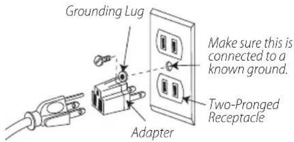
(Fig. C) can be used to temporarily connect this plug to a two-contact grounded receptacle. The adapter (Fig. C) has a rigid lug extending from it that MUST be connected to a permanent earth ground, such as a properly grounded receptacle box.

CAUTION: In all cases, make certain the receptacle is properly grounded. If you are not sure, have a qualified electrician check the receptacle.
Fig. B
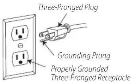
Fig. C
The label on your tool may include the following symbols. The symbols and their definitions are as follows:
V....volts
Hz hertz
min...... minutes
or DC.....direct current
Class | Construction (grounded)
.../min.....per minute
BPM.....beats per minute
≈ or AC/DC....alternating or direct current
Class II Construction (double insulated)
n_0 ..... no load speed n ..... rated speed
earthing terminal
⚠️ ...... safety alert symbol
▲......visible radiation
......avoid staring at light
...... wear respiratory protection
wear eye protection
○ .... wear hearing protection
read all documentation
SAVE THESE INSTRUCTIONS FOR FUTURE USE
ENGLISH
Motor
Be sure your power supply agrees with the nameplate marking. Voltage decrease of more than 10% will cause loss of power and overheating. These tools are factory tested; if this tool does not operate, check power supply.
TOOLS NEEDED FOR ASSEMBLY
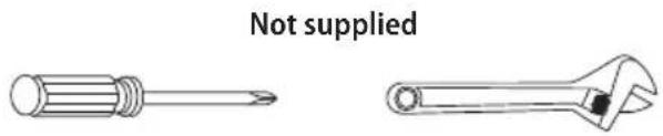
Phillips Screwdriver Adjustable Wrench
UNPACKING YOUR BENCH GRINDER
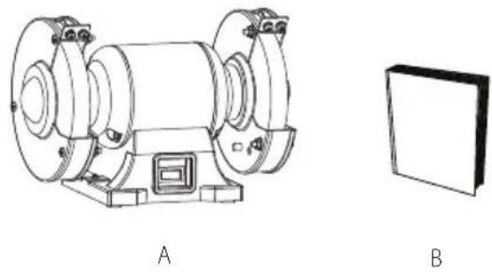
CARTON CONTENTS
Unpacking And Checking Contents
Carefully unpack the grinder and all its parts, and compare against the list below and the illustration to the right. Place the bench grinder on a secure surface and examine it carefully.

NING: To avoid injury from unexpected starting or electrical shock, do not plug the power cord into a source of power during unpacking and assembly. The cord must remain unplugged whenever you are adjusting/assembling the grinder.

WARNING: The grinder is heavy and should be lifted with care. If needed, get the assistance of someone to lift and move the grinder.

WARNING: If any part is missing or damaged, do not attempt to assemble the grinder, or plug in the power cord until the missing or damaged part is correctly replaced.
C
D
E
natural_image
Four cylindrical batteries arranged in a row, no text or symbols visibleF
Table of Loose Parts
ITEM DESCRIPTION Q'TY
| A. | Bench grinder | 1 |
| B. | Instruction manual | 1 |
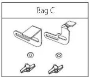
| C. | Left / Right tool rest assembly | 2 sets |
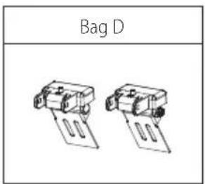
| D. | LED work light | 2 |
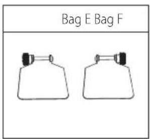
| E. | Eye shield assembly | 2 sets |
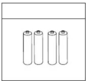
| F. | LED work light battery - AAA | 4 |

WARNING: Many illustrations in this manual show only portions of the bench grinder. This is intentional so that points being made in the illustrations can be highlighted. Never operate this bench grinder without all guards securely in place and in good operating condition.
ASSEMBLY AND ADJUSTMENTS
Estimated Assembly Time:

10 - 20 Minutes.
WARNING: To avoid injury, do not connect this bench grinder to the power source until it is completely assembled and adjusted, and you have read and understood this Instruction Manual.

WARNING: To reduce the risk of injury, turn unit off and disconnect it from power source before installing and removing accessories, before adjusting or when making repairs. An accidental start-up can cause injury.
Installing Tool Rests (Fig. D)
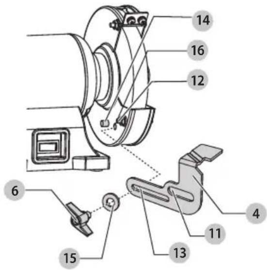
- Bag "C" - Attach the right tool rest 4 to the grinder as the upper slot 11 to the nut 12 and lower slot 13 to the protrude cylinder 14. Place the tool rest lock knob 6 through the washer 15 and lower slot 13 into the hole 16 to lock the tool rest 4 in place.
NOTE: The V grooved tool rest must mounts on the right side of grinder.
- Repeat the above steps for installing the left tool rest.
NOTE: When in use, the tool rests should be adjusted to within 1/8 in. (3.2 mm) of the grinding wheel or other accessory being used.
Fig. D
Installing The LED Light And Eye Shiled Assembly (Fig. E, F)
-
Bag "D"- Remove the two composite screws 17 from the grinder and then tighten the LED light assembly 18 to grinder with the two composite screws 17 using a Philips screwdriver. (Fig. E)
-
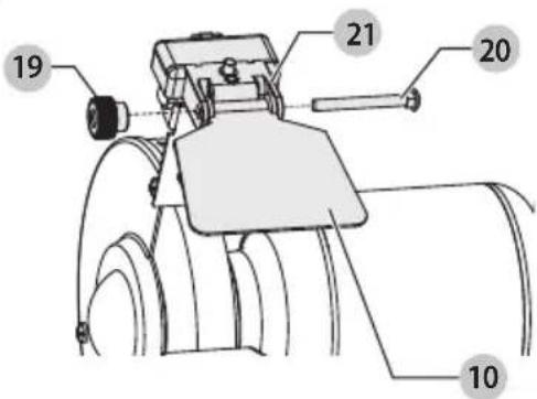
Bag "E" - Loosen the lock knob 19 counterclockwise to remove the carriage bolt 20 from eye shield 10. Attach one eye shield 10 to the support bracket 21 of the LED light assembly. Tighten the eye shield 10 by using the carriage bolt 20 and lock knob 19 as the way shown in Fig. F.
-
Repeat the above steps for installing the other LED light and eye shield assembly.
NOTE: Adjust eye shidlds to appropriate distance from tool rests avoiding interference when operation.
Fig. E
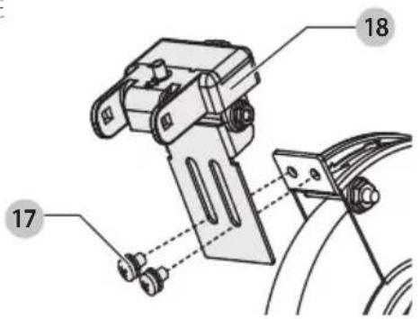
Fig. F
Changing Grinding Wheels
(Fig. G, H, I, J, K)

CAUTION: Turn off and unplug the bench grinder. Use only grinding wheels that measure 6 in.
(150 mm) in diameter. This tool has 1/2 in. (12.7 mm) arbors on both sides.
NOTE: See page 12 for information on wire or buffing wheels (not included).
-
Raise the eye shield 10 out of the way and adjust the spark guard 9 in its highest setting.
-
Loosen the tool rest lock knob 6 and remove the tool rest assembly 7.
-
Remove three screws 22 and lock nuts 23 from the left side wheel cover and then remove the wheel cover 24.
-
To prevent wheel rotating, place a wood wedge 25 (not supplied) between the wheel and the wheel cover as shown in Fig. H.
NOTE: Using a metal object, like a screwdriver, is not recommended as it may damage the grinding wheel.
- Loosen the hex nut 26 by an adjustable wrench as show in Fig. I.
NOTE: The nut on the left side of the grinder has a standard left-hand thread (turn clockwise to loosen). The one on the right side has a right-hand thread (turn counterclockwise to loosen). Both wheel nuts tighten
English
when turning toward the rear of the grinder and loosen when turning toward the front of the grinder.
- Remove the hex nut 26, the outside wheel flange 27 and the wheel 8.
- Inspect the wheel 8 for cracks, chips or any other visible damage (other than normal wear) and discard if such damage is found. Inspect the blotter/cardboard disc for damage. If the blotter id missing or severely damaged, replace it with a piece of thin cardboard of blotter paper cut in the same shape. NEVER USE A GRINDING WHEEL WITHOUT A BLOTTER.
- Install the new wheel and make sure both wheel flanges 27, 28 are in place with the concave sides toward wheels.
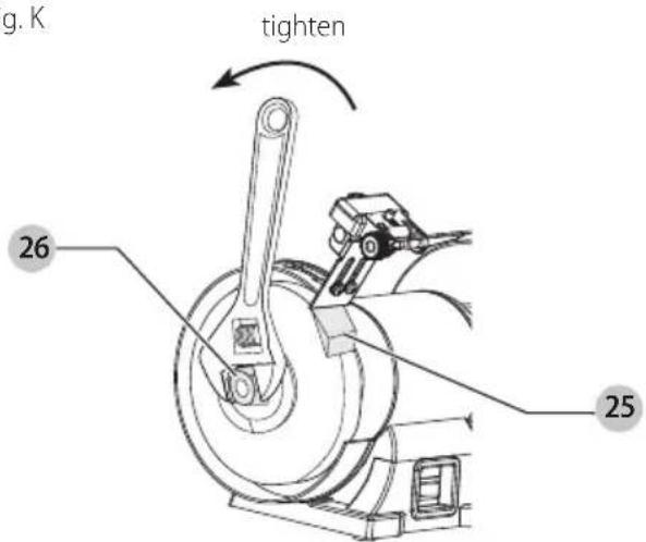
- To prevent wheel rotating, place a wood wedge 25 (not supplied) between the wheel and the wheel cover as shown in Fig. K.
- Tighten the hex nut 26 by an adjustable wrench. nOTE: Do not overtighten the nut as this can crack the grinding wheel.
- Replace the wheel cover 24 and screws 22.
- Reinstall and adjust the tool rest to 1/16 in. (1.6 mm) away from the wheel and tighten securely.
- Adjust the eye shield 10 to a point between your eyes and the wheel.
Fig. G
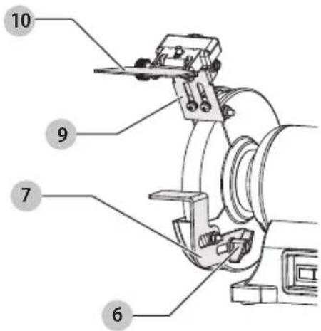
Fig. H
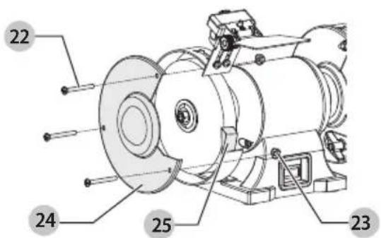
Fig.1
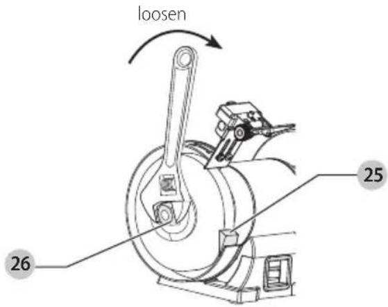
Fig. J
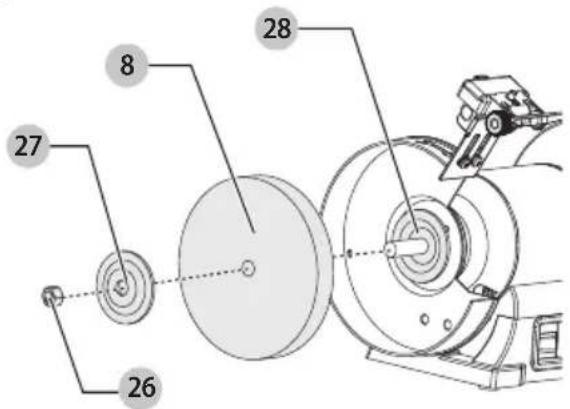
Fig. K
Mounting The Tool On A Workbench (Fig. L)
NOTE: FIRMLY BOLT THE GRINDER TO A WORK BENCH OR LEG STAND to gain maximum stability for your machine.
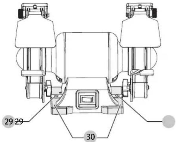
- Using the base of the bench grinder as a template, mark the bench through two holes 29 in the casting.
- Bolt the bench grinder on the bench with bolts, washers and nuts.
nOTE: The mentioned fasteners are not supplied with the machine.
Fig. L
Transporting The Grinder (Fig. L)

WARNING: To reduce the risk of injury, turn off the grinder and disconnect it from power source before installing and removing accessories, adjusting and making repairs. An accidental start-up can cause injury.
In order to conveniently carry the bench grinder from place to place, hold the left and right side of the grinder base 30 for transportation.
Change Batteries (Fig. M)

WARNING: Unplug your grinder. Failure to unplug your saw could result in accidental starting and causing possible serious personal injury.
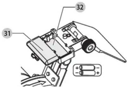
- Bag "F" - Open the battery cover 31.
- Insert two AAA batteries into the case 32. If replacing the batteries, take out the old batteries and replace with new AAA batteries. Dispose off old batteries properly.
- Replace the battery cover 31.
NOTE: Replace with batteries that have a rating of
1.5 volts (Number 4 series and AAA size or equivalent). When replacing the batteries, the battery guide should be thoroughly cleaned. Use a soft paintbrush or similar device, to remove all sawdust and debris.

WARNING: Do not mix old and new batteries. Do not mix alkaline, standard (carbon - zinc), or rechargeable (nickel - cadmium) batteries.
Fig. M
OPERATION
Starting And Stopping The Grinder (Fig. N)

WARNING: To avoid injury, always keep the plug disconnected from the power source and switch turned OFF until the grinder is completely assembled and adjusted properly.
The ON/OFF switch 5 is located on the front of the grinder. To turn the grinder on, press the switch 5 to the "I" position. To turn the grinder off, press the switch 5 to the "O" position.
Fig. N
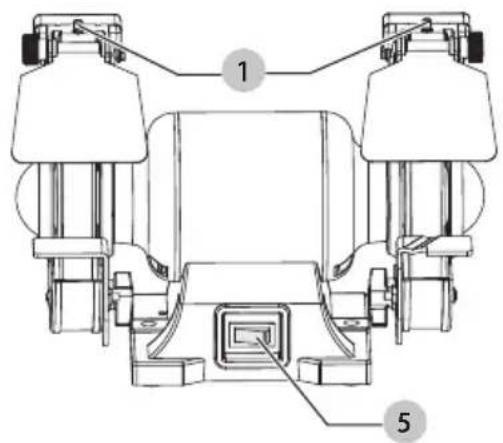
Using The Led Light (Fig. N)
- Press the LED light switch 1 down to turn the LED light "ON".
- Press the LED light switch 1 again to turn the LED light "OFF".
General Operation

WARNING: Keep all bystanders a safe distance away from the tool and not in direct line, front or back of the grinder.
- Your bench grinder has a medium wheel (60 grit) for medium material removal and general purpose grinding, and a coarse wheel (36 grit) for fast material removal.
- To operate the bench grinder, always wear safety glasses and turn the tool on while standing at the side and not in front of the grinder. Allow it to reach full speed before grinding.
- Hold the workpiece firmly against the tool rest. Hold very small pieces with pliers or other suitable clamps.
- Feed the workpiece smoothly and evenly into the grinding wheel.
- Move the workpiece slowly and avoid jamming the workpiece against the wheel. If the wheel tends to slow down from excessive force, you should occasionally release the pressure to let the wheel return to full speed.
- The grinding wheels supplied with this unit are designed for different types of steel, wrought iron, and bronze.
English
- Never sharpen or grind anything made of aluminum, brass, copper, wood, plastic or any other non-metallic materials.

WARNING: Grind only on the face of the grinding wheel and never the side of it.

CAUTION: Prolonged grinding will cause most materials to become hot. Use care when handling such materials.
Scissors
If possible, take the scissors apart to make the sharpening operation easier and safer. Remove material only from the outside surface and work from the heavy end of the blade toward the tip.
Knives
Remove metal from both faces of most knives, working from the heavy end of the blade toward the tip.
Screwdrivers
The end of a properly sharpened screwdriver will be a perfect rectangle, absolutely flat and perpendicular to the center line of the shank. The two sides and two faces will taper outward from the edge of the shoulder or shank. They should be flat with intersecting faces perpendicular. Hold each face of the screwdriver against the wheel to true it up, then ease the end straight into the stone to grind it true.
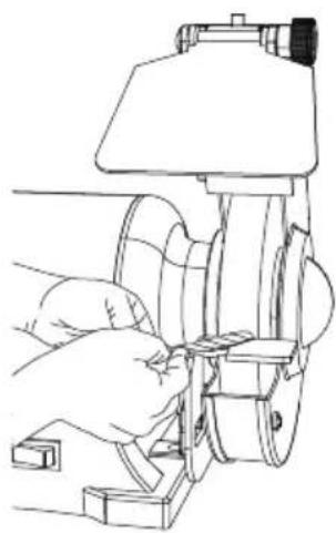
Twist Drill Bits (Fig. 0)
Drill bits are best sharpened on a sharpening jig, available at most hardware stores, but can be "dressed up" on your grinder. Begin on one side of the point at the existing angle, then twist the bit while maintaining a constant angle with grinding surface. Sharpen only the tip. This technique requires considerable practice, so take your time and make a few "dry runs" first with the grinder off. Be sure to maintain the original cutting edge angle as this is important to the efficiency of your bits. One tool rest has a V-groove that is correctly angled for most drill bits.
Fig. 0
natural_image
Line drawing of a hand operating a mechanical device with a tool (no text or symbols)Lawn Mower Blades
Lawn mower blades are usually sharpened on only one side and dressed up slightly on the other. After sharpening, be sure to balance the blade by removing additional material from the heavy end. There are a number of inexpensive cone balancers on the market for this purpose. Unbalanced blades can cause serious crank shaft damage to your lawn mower. Always remove spark plug wires from the mower before servicing the blades to prevent accidental starting.
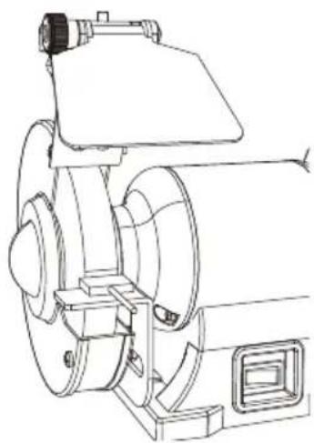
Dressing A Grinding Wheel (Fig. P)
Bring the dressing tool forward on the tool rest until it touches the high point on the face of the wheel. Dress the wheel by moving the dressing tool back and forth. Repeat this operation until the face of the grinding wheel is clean and the corner of the wheel is square.
nOTE: A wheel dressing tool is NOT provided with the grinder.
nOTE: DO NOT use the wheel dressing tool on wire wheels.
Fig. P
natural_image
Technical line drawing of a mechanical device with no visible text or symbolsInstalling Wire Wheel Or Buffing Wheels (Not included)
When replacing the grinding wheel with a wire wheel or buffing wheels, it is necessary to place a spacer (not included) on the spindle shaft BEFORE installing the inner flange, wheel, outer flange and wheel nut.

WARNING: Since accessories such as a wire wheel or buffing wheel may not have been tested with this product, use of such accessories could be hazardous. All grinding wheels or accessories must fit within the confines of the guard and must be rated higher than the recommended speed as marked on the bench grinder nameplate.
MAINTENANCE

WARNING: For your own safety, turn switch "OFF" and remove plug from power source outlet before adjusting and maintaining your bench grinder. If power cord is worn, cut or damaged in any way, have it replaced immediately.
General Maintenance
-
Regularly check the tool and use a soft brush to remove accumulated dust.
-
Use only mild soap and damp cloth to clean the tool. Do not use alcohol, petrol or other similar cleaning agents.
-
Do not make contact with the grinding wheels with any damp cloth.
-
Never let any liquid get inside the tool; never immerse any part of the tool into a liquid.
-
Wear safety goggles to protect your eyes while cleaning.
-
Always make sure the eyeshields are transparent and not blocking the view of the grinding wheel.
-
In normal use, grinding wheels may become cracked, grooved, rounded at the edges, chipped, out of true or loaded with foreign material. Cracked wheels should be replaced IMMEDIATELY. While any of the other conditions can be remedied with a dressing tool (included), new wheels sometimes require dressing to make them round.
-
If you must replace a wheel be sure to obtain one with a safe rated speed at least as high as the "NO LOAD" RPM marked on your grinder's nameplate. Replacement wheels must have a 1/2 in. (12.7 mm) center hole, 6 in. (150 mm) diameter and should be a maximum of 3/4 in. (20 mm) wide. Test new wheels for cracks and maintain the existing sequence of retaining hardware. Be sure the tool is unplugged before attempting repairs.
-
If replacing the batteries, take out the old batteries and replace with new AAA batteries. When replacing the batteries, the battery guide should be thoroughly cleaned. Use a soft paintbrush or similar device, to remove all sawdust and debris. Dispose off old batteries properly. Do not mix old and new batteries. Do not mix alkaline, standard (carbon - zinc), or rechargeable (nickel - cadmium) batteries. Batteries are to be inserted with the correct polarity. Do not charge the battery which is not a rechargeable battery.

WARNING: Never use caustic agents to clean the plastic parts of the tool.

WARNING: Water must never come into contact with the grinder.

WARNING: The use of any other accessories is not recommended and may result in serious injury.
Free Warning Label Replacement:
If your warning labels become illegible or are missing, call 1-888-331-4569 for a free replacement.

TROUBLESHOOTING GUIDE
BE SURE TO FOLLOW SAFETY RULES AND INSTRUCTIONS
For assistance with your product, visit our website at www.craftsman.com for a list of service centers, or call CRAFTSMAN at 1-888-331-4569.
PLEASE READ THE FOLLOWING: The manufacturer and/or distributor is providing the buyer with a parts list and assembly diagram in this manual as a reference tool only. Neither the manufacturer nor distributor make any representation or warranty of any kind to the buyer regarding the accuracy of the list or diagram or that buyer is qualified and able to make any repairs or replace any parts of the product. The manufacturer and/or distributor expressly recommend: that all repairs and/or part replacements only be undertaken by a certified and licensed technician, and not by the buyer. The buyer assumes all risk and liability, including injuries to persons and damage to property, associated with and arising out of any attempt of the buyer at repairs or replacement of parts to the product.
| PROBLEM PROBLEM CAUSE SUGGESTED CORRECTIVE ACTION | ||
| Motor will not run. 1. | Not plugged into power outlet.2. Switch is not in ON position.3. Motor cord cut or abraded.4. Plug on cord is faulty.5. Faulty motor.6. Fuse on circuit breaks open. | Plug it into the power outlet.Turn the switch ON.Contact Service Center or Authorized Service Station.Contact Service Center or Authorized Service Station.Contact Service Center or Authorized Service Station.Re-set; may be too many machines on line. |
| Grinding wheel vibrates or shakes. | Grinding wheel is not fixed properly.Other. | Adjust grinding wheel properly. See ADJUSTMENT section.Contact Service Center or Authorized Service Station. |
Register Online
Thank you for your purchase. Register your product now for:
- WARRANTY SERVICE: Registering your product will help you obtain more efficient warranty service in case there is a problem with your product.
- CONFIRMATION OF OWNERSHIP: In case of an insurance loss, such as fire, flood or theft, your registration of ownership will serve as your proof of purchase.
- FOR YOUR SAFETY: Registering your product will allow us to contact you in the unlikely event a safety notification is required under the Federal Consumer Safety Act.
Register online at www.craftsman.com/registration
Three Year Limited Warranty
CRAFTSMAN will repair or replace, without charge, any defects due to faulty materials or workmanship for one year from the date of purchase. This warranty does not cover part failure due to normal wear or tool abuse. For further detail of warranty coverage and warranty repair information, visit www.craftsman.com or call 1-888-331-4569. This warranty does not apply to accessories or damage caused where repairs have been made or attempted by others. THIS LIMITED WARRANTY IS GIVEN IN LIEU OF ALL OTHERS, INCLUDING THE IMPLIED WARRANTY OF MERCHANTABILITY AND FITNESS FOR A PARTICULAR PURPOSE, AND EXCLUDES ALL INCIDENTAL OR CONSEQUENTIAL DAMAGES. Some states do not allow limitations on how long an implied warranty lasts or the exclusion or limitation of incidental or consequential damages, so these limitations may not apply to you. This warranty gives you specific legal rights and you may have other rights which vary in certain states or provinces.
90 DAY MONEY BACK GUARANTEE
If you are not completely satisfied with the performance of your CRAFTSMAN Power Tool, Laser, or Nailer for any reason, you can return it within 90 days from the date of purchase with a receipt for a full refund – no questions asked.
LATIN AMERICA: This warranty does not apply to products sold in Latin America. For products sold in Latin America, see country specific warranty information contained either in the packaging, call the local company or see website for warranty information.
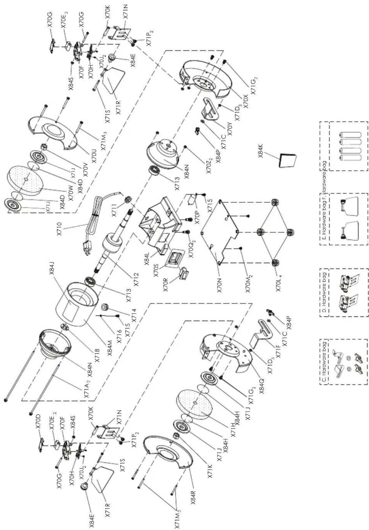
PARTS LIST
6" (150 mm) Bench Grinder
Parts list for bench grinder
I.D.NO. Description Size Q'ty
| X70D BATTERY COVER 2 | |||
| X70E AAA BATTERY 4 | |||
| X70F LED ASSY 2 | |||
| X70G SMALL CARRIAGE BOLT M5*60 2 | |||
| X70H LAMP COVER 2 | |||
| X70J PHILIPS SCREW ST2.9*8 4 | |||
| X70K | BUSHING | 2 | |
| X70L RUBBER FOOT | 4 | ||
| X70M | PHILIPS SCREW AND FLAT WASHER | M4*6 | 2 |
| X70N BOTTOM PLATE | 1 | ||
| X70P | CAPACITOR | 1 | |
| X70Q PHILIPS SCREW AND SPRING WASHER | M6*18 2 | ||
| X70R | SWITCH | 1 | |
| X70S SWITCH PLATE | 1 | ||
| X70U RIGHT SAFETY GUARD COVER | 1 | ||
| X70V | HEX NUT | 1 | |
| X70W | GRINDING WHEEL | 60# | 1 |
| X70X | RIGHT SAFETY GUARD | 1 | |
| X70Y | RIGHT TOOL REST | 1 | |
| X70Z | HEX NUT | 2 | |
| X710 | POWER CORD | 1 | |
| X711 | CORD CLIP | 1 | |
| X712 | ROTOR | 1 | |
| X713 | BALL BEARING | 2 | |
| X714 | CORD BUSHING | 1 | |
| X715 | PHILIPS SCREW WITH SPRING WASHER & FLAT WASHER | M4*8 | 2 |
| X716 | TOOTHED WASHER | 1 | |
| X718 | WAVY WASHER | 1 | |
| X71A | PHILIPS SCREW AND FLAT WASHER | M4*118 | 2 |
| X71C | FLAT WASHER | 2 | |
| X71D HEX NUT | 6 | ||
| X71F LEFT TOOL REST | 1 | ||
| X71G PHILIPS SCREW AND SPRING WASHER | M5*10 4 | ||
| X71H GRINDING WHEEL | 36# | 1 | |
| X71J FLANGE | 4 | ||
| X71K | HEX NUT | 1 | |
| X71M | PHILIPS SCREW M5*42 6 | ||
| X71N EYESHIELD BRACKET | 2 | ||
| X71P | PHILIPS SCREW WITH SPRING WASHER AND FLAT WASHER | M5*8 | 4 |
| X71R | EYESHIELD | 2 | |
| X71S SMALL CARRIAGE BOLT M5*55 2 | |||
| X84D GRINDING WHEEL WARNING LABEL | 2 | ||
| X84E EYESHIELD LOCKING KNOB | 2 | ||
| X84H GRINDING WHEEL WARNING LABEL | 2 | ||
| X84J CAUTION LABEL | 1 | ||
| X84K | INSTRUCTION MANUAL | 1 | |
| X84L BASE | 1 | ||
| X84M | STATOR | 1 | |
| X84N END CAP | 2 | ||
| X84P | LOCKING KNOB | M8*9 | 2 |
| X84Q LEFT SAFETY GUARD | 1 | ||
| X84R | RIGHT SAFTY GUARD COVER | 1 | |
| X84S HEX NUT | 2 | ||
NOTES
NOTES
NOTES





- Definitions: Safety Alert Symbols and Words
- COMPONENTS
- PRODUCT SPECIFICATIONS
- 6" (150 mm) Bench Grinder CMXEGAR500
- GENERAL POWER TOOL SAFETY WARNINGS
- SAVE ALL WARNINGS AND INSTRUCTIONS FOR FUTURE REFERENCE
- 1) Work Area Safety
- 2) Electrical Safety
- 3) Personal Safety
- 4) Power Tool Use and Care
- 5) Service
- BENCH GRINDER SAFETY
- English
- PROPOSITION 65 WARNING
- ELECTRICAL SPECIFICATIONS AND SAFETY
- Power supply and motor specifications
- Grounding instructions
- GUIDELINES FOR EXTENSION CORDS USE THE PROPER
- SAVE THESE INSTRUCTIONS FOR FUTURE USE
- Motor
- CARTON CONTENTS
- Unpacking And Checking Contents
- Table of Loose Parts
- ASSEMBLY AND ADJUSTMENTS
- Estimated Assembly Time:
- - 20 Minutes.
- Installing Tool Rests (Fig. D)
- Installing The LED Light And Eye Shiled Assembly (Fig. E, F)
- Changing Grinding Wheels
- (Fig. G, H, I, J, K)
- Mounting The Tool On A Workbench (Fig. L)
- Transporting The Grinder (Fig. L)
- Change Batteries (Fig. M)
- OPERATION
- Starting And Stopping The Grinder (Fig. N)
- Using The Led Light (Fig. N)
- General Operation
- Scissors
- Knives
- Screwdrivers
- Twist Drill Bits (Fig. 0)
- Lawn Mower Blades
- Dressing A Grinding Wheel (Fig. P)
- Installing Wire Wheel Or Buffing Wheels (Not included)
- MAINTENANCE
- General Maintenance
- Free Warning Label Replacement:
- TROUBLESHOOTING GUIDE
- BE SURE TO FOLLOW SAFETY RULES AND INSTRUCTIONS
- Register Online
- Three Year Limited Warranty
- DAY MONEY BACK GUARANTEE
- PARTS LIST
- NOTES
Brand : Craftsman
Model : CMXEGAR500
Category : Grinder